1
CVS-126
CVS-126 Instruction Manual
Doc No. 0093132702
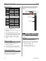
Document Revision History
No.
Doc. No / Rev. No.
Date Revised
Revised Content
0
0093132702-00
09/04/2008
First edition
1
0093132702-01
25/05/2008
Chapter all
2
3
4
5
6
7
8
9
10
Revision criteria for document number/version number
If any contents of the document has been revised, the version number is altered on the cover
sheet and corresponding chapter revised, while the other chapters remain unchanged. The
document number is designated lower right on the cover sheet and at the left or right part of every
footer.
Prohibition of copy/reprint
No part of this manual shall be reprinted or copied by any means without written permission by
Koden Electronics Co., Ltd.
Disclaimer
The specifications and technical issues described in this manual are subject to change without
notice. Koden Electronics Co., Ltd. has no responsibility for any human and physical damage or
failure caused by the interpretive error of this manual.
0093132702-01
i
Important Notice
CVS-126
Important Notice
• The re-use and transcription of Instruction Manual (hereafter called this manual) needs permission
of our company. Our company prohibits the un-authorized re-use and transcription.
• If this manual is lost or damaged, consult our dealer or our company.
• The specification of our products and the content in the Instruction Manual are subject to changed
without notice.
• In the explanation of this manual, the content displayed on the menu of product may be different.
The keys and menus in the illustration may differ in physical font and shape. And some parts may
be omitted.
• Our company is not liable for damage and trouble arisen from misunderstanding the content
described in this manual.
• Our company is not liable for earthquake, lightning, fire for which our company is not responsible,
action by third party, other accident, customer’s unintended error/abuse and damage caused by the
use under other abnormal condition.
• Our company is not liable for damage of accompaniment (change/loss of memorized content, loss
of business profit, stop of business) arisen from use or failure of our product.
• If the stored data is changed or lost, irrespective of any cause of trouble and damage, our company
is not liable for it.
• Our company is not liable for any damage arisen from malfunction caused by combination of
software and connected equipment we do not involve.
ii
0093132702-01
CVS-126
For Your Safe Operation
For Your Safe Operation
Pictorial used in this Instruction Manual
This Instruction Manual uses the following pictorials. Understand the meaning of each pictorial and
implement the maintenance and inspection.
Symbol
Meaning
Mark for warning
This symbol denotes that there is a risk of death or serious injury when not
dealing with it correctly.
Mark for danger high voltage
This symbol denotes that there is a risk of death or serious injury caused by
electric shock when not dealing with it correctly.
Mark for caution
This symbol denotes that there is a risk of slight injury or damage of device
when not dealing with it correctly.
Mark for prohibition
This symbol denotes prohibition of the specified conduct. Description of the
prohibition is displayed near the mark.
Caution Item on Handling
Do not disassemble or modify. It may leads to trouble, fire, smoking or
electric shock. In case of trouble, contact our dealer or our company.
In case of smoke or fire, boat power off and the power of this unit. It may
cause fire, electric shock or damage.
Be cautious of remaining high voltage.
A high voltage may remain in the capacitor for several minutes after you
have powered off. Before inspecting inside, wait at least 5 minutes after
powering off or discharge the remaining electricity in an appropriate manner.
Then, start the work.
The information displayed in this unit is not provided directly for your
navigation. For your navigation, be sure to see the specified material.
0093132702-01
iii
For Your Safe Operation
CVS-126
Use the specified fuse. If un-specified fuse is used, it may cause a fire,
smoke or damage.
Whenever transmitting, be sure to submerge the transducer in water first. If
transmitted without submerging the transducer, it may be damaged.
Caution Item on Equipment
Be careful of a high voltage inside.
A high voltage, which may risk your life, is used. This high voltage remains
in the circuit after you have powered off switch. To prevent touching the high
voltage circuit inadvertently, the protection cover is provided to the high
voltage circuit and the high voltage caution label is affixed. Ensure to power
off switch for your safety and discharge the electricity remaining in the
capacity before starting to check. An engineer authorized by our company
should inspect and maintain
Be sure to power off in the boat.
If the power switch is inadvertently powered on during work, you will be
electrified. To prevent such accident from occurring, ensure to power off in
the boat and the power of equipment. Furthermore, it is safer to hang the
caution tag described as [Under Work] near the power switch of equipment.
Be careful of dust
Inhaling dust may cause A respiratory disease. When cleaning the inside of
equipment, be careful not to inhale dust. Wearing a safety mask is
recommended.
Caution on location of equipment
Do not install the equipment where it is excessively damp and suffers from
excessive water drops.
Escaping from static electricity
The static electricity may be generated from the carpet on the floor in the
cabin or clothes made of synthetic fiber. The static electricity may destroy
the electronic parts on the circuit board. Handle the circuit board, taking the
measure of static electricity free.
Install the transducer at the location where it is not affected by bubble and
noise The bubble and noise seriously degrade the performance of this unit.
iv
0093132702-01
CVS-126
Contents
Contents
Document Revision History....................ⅰ
Selection of Echo sounder mode
Important Notice .....................................ⅱ
and Depth mode ........................ 1-8
For Your Safe Operation ........................ⅲ
Fine-adjusting the Auto Gain ..... 1-9
Contents .................................................ⅴ
Adjust the gain manually. ........... 1-9
Introduction.............................................. ⅶ
Easy Gain Adjustment................ 1-9
Confirm the gain state.............. 1-10
System Configuration............................... ⅷ
1.7
Configuration of Equipment...................... ⅹ
Select the event. ...................... 1-10
Preset the destination. ............. 1-10
Chapter 1 Basic Operation......................1-1
1.1
Store the image........................ 1-11
How to use the key .................... 1-1
Start the homing....................... 1-11
How to remove the protection
cover .......................................... 1-2
1.8
Preset of 【FUNC】 key ........ 1-12
Display unit ................................ 1-2
Power On/Off ............................. 1-3
Power on .................................... 1-3
Power off .................................... 1-3
1.3
1.4
1.9
Chapter 2 How to use the Menu .............2-1
2.1
How to operate the menu .......... 2-1
Display the menu. / Stop the
LCD Brilliance Adjustment ......... 1-4
display of menu.......................... 2-1
Adjustment of LCD Brilliance ..... 1-4
Menu Operation ......................... 2-1
Brightness Adjustment of Panel
2.2
Change of Image Speed ............ 2-2
Brilliance .................................... 1-4
2.3
Rejection of Interference............ 2-2
Interference Rejection................ 2-2
Switch-over of Menu .................. 1-4
2.4
Dual Frequency.......................... 1-5
2.5
Rejection of Noise...................... 2-3
Noise Rejection.......................... 2-3
Zoom (Low frequency, high
frequency) .................................. 1-5
Color Rejection of Weak Echo ... 2-2
Color Rejection .......................... 2-2
high frequency) .......................... 1-4
1.6
Operation of VRM .................... 1-13
Alarm of Power Voltage ............. 1-3
Normal Image (Low frequency,
1.5
Use of 【FUNC】 key ............ 1-12
How to use the 【FUNC】 key1-12
When removing the CVS-126
1.2
Use of 【EVENT】 key .......... 1-10
2.6
Setting of Shift............................ 2-3
Navigation Menu
Setting of Fixed Shift.................. 2-3
(NAV1, NAV2) ............................ 1-7
Setting of Auto Shift. .................. 2-3
Switch-over of Range................. 1-8
2.7
Setting of Zoom Range .............. 2-3
Set the range switching to auto
2.8
Setting of Zoom Start ................. 2-4
range. ......................................... 1-8
2.9
Setting of Background Color...... 2-4
Gain Adjustment......................... 1-8
2.10 Setting of White Line.................. 2-4
Basic Operation of Gain............. 1-8
2.11 Preset of Range ......................... 2-5
2.12 Setting of Alarm.......................... 2-5
0093132702-01
v
Contents
CVS-126
Image Swap ............................. 2-14
Stopping the alarm sound ..........2-5
Setting the alarm ........................2-6
Release the alarm. .....................2-6
Confirm the alarm state..............2-6
2.13 Preset/ WPT edit/ WPT delete of
Destination.................................2-6
NAV Start. ...................................2-6
Cancel the NAV. .........................2-7
Chapter 3 How to use the system menu .3-1
3.1
Display of System Menu ............ 3-1
3.2
Setting of External In/Out ........... 3-1
3.3
Setting of Correct Item ............... 3-2
3.4
Setting of System Item ............... 3-2
3.5
Setting of Basic Set Item............ 3-3
3.6
Maintenance Menu..................... 3-3
Edit the destination.....................2-7
Delete the destination. ...............2-8
Recall the image stored and
preset it as a destination. ...........2-8
2.14 Store/Recall/Deletion of Image...2-9
Store the image. .........................2-9
Recall the stored image. ............2-9
Delete the stored image. ............2-9
Chapter 4 Maintenance and Inspection...4-1
4.1
Inspection ................................... 4-1
4.2
Cleaning ..................................... 4-1
4.3
Fuse Replacement ..................... 4-1
4.4
If you suspect a trouble .............. 4-2
4.5
Diagnostic Test ........................... 4-3
Chapter 5 Installation ..............................5-1
Add the comment to the stored
5.1
Item of Caution on Installation.... 5-1
image........................................2-10
5.2
Installation of CVS-126 Display
2.15 Selection of Zoom ....................2-10
unit .................................................. 5-2
2.16 Selection of NAV Display ......... 2-11
5.3
Installation of Transducer ........... 5-5
Type of NAV Display................. 2-11
5.4
Wiring ......................................... 5-7
Dividing Method of Display....... 2-11
5.5
Serial Data................................ 5-10
Selection of NAV Menu ............ 2-11
2.17 Explanation of Sonar ................2-12
Switch-over of Sonar Tone .......2-12
Connection of External
Chapter 6 Table Attached........................6-1
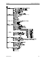
6.1
Menu List.................................... 6-1
6.2
Specification ............................... 6-3
6.3
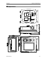
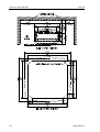
Appearance ................................ 6-4
Speaker ....................................2-12
2.18 Explanation of Menu Item ........2-12
TVG ..........................................2-12
Change the TX power. .............2-12
Display the A scope. / Stop the
display of A scope. ...................2-13
Change the display color of echo
sounder image..........................2-13
Change the depth value. ..........2-13
Display the water temp graph. /
Stop the display of water temp
graph. .......................................2-13
Disp Width ................................2-13
vi
0093132702-01
CVS-126
Introduction
Introduction
The CVS-126 is a Dual frequency (50kHz/200kHz) Color LCD display echo sounder.
This unit equipped with digital process displays the circumstance in the water under all conditions,
matching with the high luminance 5.7 inch LCD.
The main features of this unit are as follows.
• With the digital reception process, the compatibility of the high resolution in a shallow depth and the
noise rejection capability in a deep depth are established. The auto mode function provides the best
image.
• The unit can be installed in an open bridge and is highly waterproof.
• Up to 10 images can be stored. If you connect the optional GPS, the homing function, that directs
your boat to navigate easily to the location desired, is available by marking the event mark when
recalling the stored image.
• The unit is designed to save power consumption. The white LED is adopted for illuminating the LCD
and the power consumption is minimal in this class. The unit emits less heat and the occurrence of
condensation is rare.
• The various alarm functions are available. (Bottom, school of fish, water temperature*, board
speed*, arrival*, XTE*, power) (Note: The mark * denotes that the connection of option is
mandatory)
• When flush-mounting, the unit can be easily installed from front side.
0093132702-01
vii
System Configuration
CVS-126
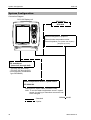
System Configuration
Connection Diagram
CVS-126 Display unit
GPS sensor
GPS-20A
External Navigation Equipment
External water temperature meter
External speaker (For speaker with amplifier)
(Prepared by a user)
TD: transducer
* (Inner-hull, through-hull)
* TD-500T-2B (Inner-hull)
* TD-500T-3B (through-hull)
(Dual frequency combination
type 50/200kHz)
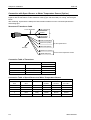
Water temperature sensor / speed sensor
ST-80/90/100
Requirement: Option cable (CW-840-0.3M)
Note: To use the water temperature sensor / speed
sensor, the wiring of transducer connector has
to be changed.
DC10.8 31.2V
: Standard
: Option
viii
0093132702-01
CVS-126
System Configuration
CVS-126 echo sounder unit
With mounting bracket and protection cover
Legend
To Transducer
connector
Standard configuration
Option
To POWER connector
CW264-2M
External power output (For GPS etc)
External speaker (For speaker with amplifier)
(Prepared by a user)
NMEA circuit input output
GPS sensor (GPS-20A)
External navigation equipment,
external water temperature meter
Red
Black -
DC10.8~31.2V
Option cable (CW-840-0.3M)
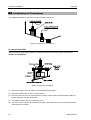
Connection to the Transducer
Connection to the water temperature sensor Water temperature sensor
/ speed sensor
ST/80/90/100
Connection to the speed sensor
Note: To use the water temperature sensor / speed sensor,
the wiring of transducer connector has to be changed.
Transducer TD-500T-3B (Dual frequency combination type 50/200kHz)
Bronze made Equipped with through-hull
Transducer TD-500T-2B (Dual frequency combination type 50/200kHz)
Plastic made Equipped with inner-hull
0093132702-01
ix
Configuration of Equipment
CVS-126
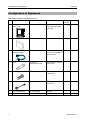
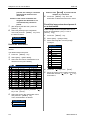
Configuration of Equipment
Standard Equipment Configuration List
No
Name of item
1
Transmission-receiver
display unit
CVS-126
2
Protection cover
C38MB12020
3
DC power cable
(Complex cable)
CW-264-2M
With 12 connector at
one end/ un-treated at
the other end
4
Fuse
F-7161-2A
Cylinder (ø6.3x32)
Normal fusion type for
main power
2
5
Trans Tapping Screw
TPT5 x 20U
For fixing CVS-126
Display unit
4
6
Cap
LTWCAP-DABCFXC1
For transducer cable
connector
1
7
Instruction Manual
CVS-126.OM.E
English
1
8
Quick Reference
CVS-126.QR.E
English
1
x
Type
Remark
600W output
with mounting bracket
and knob
Weight/
Length
Quantity
1.3 kg
1
150g
1
2m
1
0093132702-01
CVS-126
Configuration of Equipment
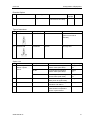
Essential Option
No
1
Name of item
Transducer
Type
Remark
Type of transducer
transducer cable (with
connector at one end)
Weight/
Length
9m
Quantity
1
Type of transducer
No
Specification
Frequency
Material
Mounting method
1
TD-500T-2B
50/200kHz
Plastic
Inner-hull
(The inner-hull kit is
needed.)
2
TD-500T-3B
50/200kHz
Bronze
Through-hull
Option List
No
1
Name of Item
Water temperature
sensor / speed
sensor
Specification
Remark
Weight/Length
ST-80
For transom mounting
Plastic made (with cable)
0.3kg/
8m
ST-90
For through-hull mounting
Plastic made (with cable)
0.6kg/
8m
ST-100
For through-hull mounting
Bronze made (with cable)
1.2kg/
8m
2
GPS sensor
GPS-20A-10M-3
For GPS measuring
(With power & signal cable)
250g/10m
3
Inner-hull kit
MFB-04
Plastic made for installing the
transducer TD-500T-2
1.3kg
4
Cable for transducer
CW-840-0.3M
Needed when using the
optional water temperature
sensor / speed sensor.
30cm
0093132702-01
xi
Chapter 1 Basic Operation
CVS-126
Chapter 1 Basic Operation
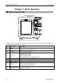
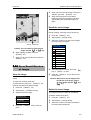
1.1 How to use the key
CVS-126 Display unit
1
2
3
5
4
6
7
8
In addition, for your convenience when operating keys other than keys in the menu by the【MENU】key,
the menu displayed automatically closes.
No.
Key Name
Explanation
1
【DISP】
It switches to the high frequency or low frequency of echo sounder
image, zoom and navigation menu.
2
【EVENT】
It notifies the external equipment of the present position. It presets the
menu. It begins a homing.
3
【Cursor】
It selects the menu item.
It changes the set value.
It moves the VRM marker.
It moves the marker for notifying the event.
4
【FUNC】
It recalls directly the item preset.
5
【MENU】
It opens or closes the menu.
6
【 RANGE 】
It changes the range setting.
7
【Knob】
Press: It recalls the gain adjustment.
Rotate: It changes the gain value.
It selects the item in the menu.
8
【BRILL 】/ Power
Press: Power on. It adjusts the brilliance and brightness of panel.
Long-press: Power off.
1-1
0093132702-01
CVS-126
Chapter 1 Basic Operation
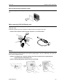
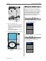
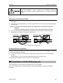
How to remove the protection cover
While widening the claws at right and left sides of protection cover, draw the protection cover towards
you.
Claw
When removing CVS-126 Display unit:
To prevent dust from entering, cap the connector at the rear of CVS-126 Display unit and the power
cable with caps.
Install the supplied cap to the transducer cable as shown in the figure and cap it.
Caution: Do not pull the cable strongly. If you do so, it will be broken.
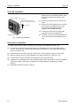
When :
The cleaning of the display goes after removing the front-frame. After removing the front-frame, use a
synthetic detergent and OA cleaner and wipe the display lightly. Then dry sufficiently, and return the
front- frame to original position.
Caution: The display has a special coating. Do not use a solvent such as paint thinner,
acetone, alcohol, and benzene, etc.
Caution: Strong rubbing may cause bruising, scratching.
0093132702-01
1-2
Chapter 1 Basic Operation
CVS-126
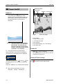
Rainbow pattern
Time mark
Range Function icon
Gain
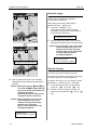
1.2 Power On/Off
Power on
1
Press the 【BRILL 】 key to power on.
The startup menu is displayed. When
started up, the memories (ROM, RAM) are
automatically checked. When checking is
normally finished, the menu below is
displayed.
L
H
School of fish Oscillation line
Fish
Depth
Dual freq image
Type of Gain
H: High frequency gain,
L: Low frequency gain
Caution: If an error occurs in the memory
check, the LED on the operation
panel blinks. The unit may not
function normally. If you suspect
trouble, contact the dealer of your
purchase or our company.
2
Language Selection at Initial Startup.
When powering on first, after the [Initialize] is
processed, the [Language] menu is displayed.
Type of Range
R: M: Manual Range, R: A: Auto Range,
R: AS: Auto Shift
Power off
1
When powering off, keep pressing the
【BRILL 】 key for 3 seconds.
The remaining time for the power to shut off
is displayed on the menu.
Language
English
日本語
Select the language with 【 】 key or 【 】 key.
(The language can be selected by rotating the
【knob】.)
Alarm of Power Voltage
If the power voltage drops below a certain level,
the
icon blinks and the alarm beeps.
Press the 【MENU】 key to decide the language.
3
1-3
After a few seconds pass, the menu
selected in 【DISP】 is displayed.
0093132702-01
CVS-126
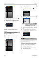
1.3 LCD Brilliance
Adjustment
Chapter 1 Basic Operation
2
Disp
NAV1/ Normal (H)
Normal (H)
Zoom (H)
Dual Freq
Zoom (L)
Normal (L)
NAV2/ Normal (L)
Adjustment of LCD Brilliance
The [Lcd brill] and [Panel brill] can be switched
every time when pressing the 【BRILL 】key.
1
Press the 【BRILL 】 key for a short period
of time to display the menu ([Lcd brill]).
2
Rotate the 【Knob】.
When “1” is selected, it is darkest. When
“10” is selected, it is brightest.
(High): High frequency
(Low): Low frequency
NAV1: Navigation display1
Lcd brill
10
3
Press the 【MENU】 key to close the menu.
Brightness Adjustment of Panel
Brilliance
The brightness of panel can be adjusted,
1
2
Press the 【BRILL 】 key for a short period
of time to display the menu ([Panel brill]).
Rotate the 【Knob】.
When “1” is selected, it is darkest. When
“10” is selected, it is brightest.
Select the display you desire to display.
NAV2: Navigation display2
3
Press the 【MENU】 key to close the menu.
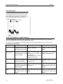
Normal Image (Low frequency, high
frequency)
Low frequency(50kHz)
Since the beam width is wide, the search range
becomes wide so that the beam can search the
deep depth.
High frequency(200kHz)
Since the beam width is narrow, it is hard to be
interfered by noise and bubble in the sea so that
the school of fish can be searched in a high
resolution.
Panel brill
10
Low frequency
(50 kHz)
3
Press the 【MENU】 key to close the menu.
High frequency
(200 kHz)
1.4 Switch-over of Menu
7 kinds of displays are provided in all. Select the
display suitable for your purpose.
1
Press the 【DISP】 key.
Your boat
Point A Sea level
Point B
School of fish
0093132702-01
Ultra-sonic
signal
1-4
Chapter 1 Basic Operation
CVS-126
Dual Frequency
The high frequency image can be displayed in
the right half side and the low frequency image
can be displayed in the left half side. Since the
beam width differs depending on frequency, the
school of fish and sea bottom look different.
Low frequency image
High frequency image
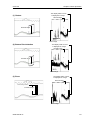
Zoom (Low frequency, high frequency)
A part of normal image can be zoomed. (1) [Bottom], (2) [Bottom Discrimination], [zoom], (4) [Bottom
Zoom] and (5) [Bottom Follow Zoom] are provided for zoom.
The unit is set to (1) [Bottom] at ex-factory. To change to other zoom display, set it in the menu. (See
[2.7 Setting of Zoom Range].)
Zoom type
Zoom start position
Zoomed range
Purpose
Bottom
It displays the position of
the bottom in the fixation
in the display bottom part.
It displays the bottom and
upper in the zoom.
It is convenient to see a
school of fish near the
bottom.
Bottom
Discrimination
It displays the position of
the bottom in the fixation
in the position of 1/4
under the display.
It displays the bottom and
upper in the zoom, it
displays under the bottom in
the ordinary.
(Under the bottom, it doesn't
display in the zoom).
It is convenient to see a
school of fish and a bottom
quality near the bottom.
Zoom
It displays a zoom start
position in the fixation at
the top of the display.
It displays in the zoom from
the zoom start position to the
range you set.
It is convenient to see the
specified range in the
zoom.
Bottom Zoom
It displays the position of
the bottom in the position
which is the same as the
ordinary display.
It displays upper side of the
bottom in the zoom except
the bottom.
It is convenient to see a
school of fish near the
bottom and the form of the
bottom.
Bottom
Zoom
It always displays the
position of the bottom in
the lower part of the
display.
It displays the bottom and
upper and lower sides in the
zoom.
It is convenient to see a
school of fish near the
bottom and the form of the
bottom.
1-5
Follow
0093132702-01
CVS-126
Chapter 1 Basic Operation
The display width of zoom
is displayed in orange.
(1) Bottom
Normal image
Zoomed range
30.0
Zoom image
(2) Bottom Discrimination
The display width of zoom
is displayed in orange.
Normal image
Zoomed range
30.0
Zoom image
The display width of zoom
is displayed in orange.
(3) Zoom
Normal image
Zoom start position
Zoomed range
30.0
Zoom image
0093132702-01
1-6
Chapter 1 Basic Operation
CVS-126
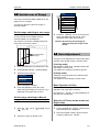
The display width of zoom
is displayed in orange.
(4) Bottom Zoom
Normal image
Zoomed range
30.0
Zoom image
The image below the bottom
is not zoomed.
(5) Bottom Follow Zoom
The display width of zoom
is displayed in orange.
Normal image
Zoomed range
30.0
Zoom image
Navigation Menu (NAV1, NAV2)
The navigation menu can be displayed at the left side on the display. To display the information other
than depth, sensors need to be connected. (See [2.16 Selection of NAV Display].)
H:9.0
R:M
Depth
H:9.0
12.6V
0.0
R:M
高
12.6V
0.0
10.0
10.0
Water temp
20.0
20.0
30.0
30.0
Range
40.0
40.0
50.0
50.0
Total range
1-7
60.0
60.0
70.0
70.0
0093132702-01
CVS-126
Chapter 1 Basic Operation
Range
1.5 Switch-over of Range
5.0
10.0
50.0
80.0
100.0
150.0
300
500
The range of measured depth displayed on the
display can be changed.
To meet your purpose, select the range of
measured depth.
Set the range switching to auto range.
By following automatically the bottom, the image
of echo sounder in the suitable range of
measured depth can be displayed.
3
Caution: By selecting the [D.range] →
[Range preset], the range can be
preset.
This mode is convenient to display always the
range from sea level to bottom.
The range value
changes
Press the 【MENU】 key to close the menu.
When the [Manual] is set, the [R : M] is
displayed at the upper side of menu.
1.6 Gain Adjustment
The gain can be adjusted in the auto mode (Echo
sounder mode, Depth mode) or manual mode.
[Cruising mode]
1
Press the [MENU] key to display the menu.
2
3
Select [Display Range] → [Range Mode].
Eliminating the weak echo, it displays clearly the
sea bottom of strong echo.
It is suitable for cruising to the fishery ground.
Select the [Auto Range].
[Fishing mode]
Range Mode
Manual
Auto Range
Auto Shift
4
It displays clearly the weak echo reflected from
the school of fish.
It is suitable for searching the school of fish.
(See [2.6 Setting of Shift].)
Basic Operation of Gain
Press the [MENU] to close the menu.
When the [Auto Range] is set, the [R : A] is
displayed a the upper side of menu.
Every time when rotating the 【Knob】, the [Gain]
and [Auto Gain Select] are switched.
Set the range switching to Manual
range.
By rotating the 【Knob】, the gain adjustment or
auto gain can be selected.
Selection of Echo sounder mode and
Depth mode
The gain adjustment can be set to [Auto Adjust].
1
2
Press the 【 】 key of 【 range 】 key or
【 】 key.
Select the range you desire to set.
0093132702-01
1
Press repeatedly the 【Knob】 until the [Auto
Gain Select] menu is displayed.
2
Select the [Depth mode] or [Echo sounder
mode] by rotating the 【Knob】.
1-8
Chapter 1 Basic Operation
CVS-126
image. Adjust properly the gain so
that the optimum image can be
always displayed.
Gain select
Manual
Cruising
Fishing
3
Press the 【MENU】 key to close the menu.
When the [Cruising mode] is set, the [A : AC]
is displayed at the upper side of menu.
When the [Fishing mode] is set, the [A : AF]
is displayed at the upper side of menu.
Over-gain
Fine-adjusting the Auto Gain
When the [Cruising mode] or [Fishing mode] is
set, the gain can be fine-adjusted.
1
Press repeatedly the 【Knob】 until the [Auto
Gain Select] menu is displayed.
2
Select the [Cruising mode] or [Fishing mode]
by rotating the 【Knob】.
3
Press the 【Knob】.
4
Adjust the gain by rotating the 【Knob】.
Every time when pressing the [Auto Gain
Select] and [Auto Gain Adjust] are
alternately displayed.
6
7
Press the 【MENU】 key to close the menu.
Stop increasing the gain just before noise
appears on the image.
5
When the [Disp] is set to other than
[Normal freq],
every time when pressing the [Knob], the
[Gain (High Frequency)] or [Gain (Low
Frequency)] → [Auto Gain Select] is
displayed.
When the [Disp] is set to the [Normal
freq],
every time when pressing the [Knob], the
[Gain (High Frequency)] -> [Gain (Low
Frequency)] → [Auto Gain Select] is
displayed.
6
7
Press the 【MENU】 to close the menu.
When pressing the 【Knob】 again, the
previous menu before pressing the
【MENU】 key is displayed.
Adjust the gain manually.
When the image of high frequency only is
displayed on the display, the high frequency gain
can be adjusted.
When the image of low frequency only is
displayed on the display, the low frequency gain
can be adjusted.
When both of the high frequency image and low
frequency image are displayed, by pressing the
[Knob], the adjustable frequency can be
changed.
Caution: If you increase the gain too much,
noise will appear on the entire
image, resulting in an unclear
1-9
Press the 【Knob】.
0
0
5
Select the [Manual] by rotating the 【Knob】.
Gain (H)
Fine-adjust the gain by rotating the 【Knob】.
Auto gain adjust
Under-gain
1
2
3
Press the 【Knob】 to display the Auto Gain
Adjustment].
4
Optimum
When pressing the 【Knob】 again, the
previous menu before pressing the
【MENU】 key is displayed.
Easy Gain Adjustment
Depending on the item of [Auto Gain Select], the
adjustment menu differs.
1
2
Rotate the 【Knob】.
3
Press the 【MENU】 to close the menu.
The gain adjustment menu is displayed and
the gain can be adjusted.
0093132702-01
CVS-126
Chapter 1 Basic Operation
Confirm the gain state.
The present set value of frequency (high
frequency or low frequency) adjusted last is
displayed at the upper left side of menu.
Example)
The high frequency gain is 8.0 → H: 8.0.
H:8.0
R:M
When presetting the destination, switch [NAV] →
[EVENT Key set] → [Store pos].
1
In the state that no other key is pressed,
press the 【 】 key or 【 】key.
2
Move the cursor (Redline) with the 【 】 key
or 【 】 key to the location to be preset as
a destination.
12.6V
1.7 Use of 【EVENT】 key
L
H
By pressing the 【EVENT】 key, three functions
of [Store Position]. [Store Image] and [Homing]
are available.
The homing is the function to instruct your boat
to navigate easily to a point where you desire to
go back.
[Save pos]: The latitude and longitude of a point
can be stored.
[Store image]: An image of the fish finder can be
stored in the internal memory.
[Homing]: The WPT navigation starts, using the
latitude and longitude of a point which is set as a
destination by pressing the 【EVENT】 key.
Simultaneously, the latitude and longitude of the
point can be stored in the destination list.
Select the event.
Select the functions when pressing the
【EVENT】 key.
1
2
Press the 【MENU】 key.
3
Change the setting of [EVENT key set].
Cursor (Redline)
3
Press the 【EVENT】 key.
When decided, the red line is drawn at the
designated location on the echo sounder
menu and the latitude and longitude of
designated location are registered in the
destination list.
At this moment, the list number of preset
destination is displayed.
Select [NAV] → [EVENT Key set].
EVENT Key set
Store pos
Store image
Homing
(Refer to [2.6 Setting of Shift ].)
4
Press the 【MENU】 to close the menu.
Preset the destination.
When you find the school of fish or tide, its
location can be preset as a destination.
(10 locations at maximum)
0093132702-01
1-10
Chapter 1 Basic Operation
CVS-126
Store the image.
L
When you find the school of fish or tide, its
location can be stored as a destination.
(10 locations at maximum)
H
When storing the image, switch [NAV] →
[EVENT Key set] → {Store pos}.
1
Press the 【EVENT】 key.
The image of echo sounder presently
displayed is stored and the list number of
stored image is displayed.
It registered in Pic list No.1
Cursor
(Redline)
L
2
After a certain time passes, the message
disappears and storing the image is finished.
Caution: If the destination list is fully filled,
the preset destination list is not
deleted, showing the message
that the image is fully filled. After
a certain time passes, the
message disappears.
H
A list of Pic is full.
It was not possible to register
It registered in the Wpt list No.1
Start the homing
When you find a school of fish or a tidal flow,
your boat can go back easily to that point.
Your boat can go back to any point on an image
you saved. (See [2.13 WPT navigation].)
4
After a certain time passes, the message
disappears and presetting the destination is
finished.
Caution: When pressing the 【EVENT】
】 key,
if [In out] → [NMEA output data] →
[TLL] is set to ON, the latitude and
longitude of location
above-designated is output to the
navigation system connected.
To perform the homing, it is necessary to select
[Navigation] → EVENT key set → [Homing].
1
In the state that no other key is pressed,
press the 【 】 key or the 【 】 key.
2
Move the cursor (red line) to a point you
desire to go back with the【 】 key or 【 】
key.
Caution: If the destination list is full, the
preset destination list is not
deleted, showing the message
that the list is fully filled.
After a certain time passes, the
message disappears.
A Wpt list is full.
It was not possible to register
1-11
0093132702-01
CVS-126
Chapter 1 Basic Operation
1.8 Use of 【FUNC】 key
L
H
When factory-shipped, the [Image Speed] is
assigned to the 【FUNC】 key. The function
settable to the 【FUNC】 key can be selected
among [Image Speed], [Interference Rejection],
[Color Rejection], [Noise Rejection], [Range
Mode], [Shift], [Zoom Range], [Zoom Start],
[Background] and [White Line]. Set the function
frequently used for your convenience.
How to use the 【FUNC】
】 key
1
2
Cursor (Redline)
3
4
Change the setting by rotating the 【Knob】.
In case of [Image speed]
Image Speed
Press the 【EVENT】 key.
When you decide, the red line is drawn on
the image of the fish finder at the point you
designate and the latitude and longitude of
the point you designate is stored in the
destination list.
At this moment, the number of the stored
destination list is displayed.
2/1
1/1
stop
1/1.5
1/2
1/2.5
1/3
1/3.5
1/4
1/4.5
The navigation display (NAV1) is displayed
and the WPT navigation starts.
12.6V
Press the 【FUNC】 key.
3
Press the 【MENU】 key to close the menu.
Preset of 【FUNC】
】 key
1
2
3
Press the 【MENU】 key.
Select [System] → [FUNC key set].
Select the function.
FUNC key set
37.0m
Note: The display of NAV1/Normal (H) is
displayed.
0093132702-01
Image Speed
IR
Color Rejection
Noise Rejection
Range Mode
Shift
Zoom Range
Zoom Start
Background Color
White L
1-12
Chapter 1 Basic Operation
4
CVS-126
Press the 【MENU】 key to close the menu.
The icons of functions preset are displayed
at the upper right side on the menu.
Image Speed
IR
Color Rejection
Noise Rejection
Range Mode
Shift
Zoom Range
Zoom Start
Background Color
White Line L
1.9 Operation of VRM
The VRM (movable marker) shown by the green
line can be moved up and down.
It is convenient to measure the depth by aligning
with the target such as school of fish.
1
Press the 【 】 key or 【 】 key. The
movable marker (straight line) is displayed.
2
Press the 【 】 key or 【 】 key. The
movable marker moves up and down.
The movable marker and the numerical of
marker depth are simultaneously
highlighted.
Marker Depth
20.0
Movable marker
When displaying dual images, if the 【 】
key or 【 】 key is pressed, the movable
marker moves to the neighboring image.
Caution: When several seconds pass after
finishing the VRM operation, the
numerical of marker depth
becomes normal display.
1-13
0093132702-01
CVS-126
Chapter 2 How to use the Menu
Chapter 2 How to use the Menu
2.1 How to operate the
menu
Adjust
D.range
Image
Alarm1
Alarm2
NAV
Disp
Sonar
Next
Display the menu. / Stop the display
of menu.
1
Press the 【MENU】 key.
The menu and explanation of operation are
displayed.
Cursor
Name of menu selected
Menu column Setting item column Setting value
Adjust
D.range
Image
Alarm1
Alarm2
NAV
Disp
Sonar
Next
Image speed
IR
Color rejection
1/1
Strong
0%
Noise rejection
0
TGV
Medium
Auto
TX power
Return
Range mode
Shift
Zoom select
Zoom range
Zoom start
Manual
0m
Bottom
10.0m
0m
Range preset
Return
2
Press the 【 】 key.
The cursor appears in the set item column.
(The cursor appears by pressing the
【Knob】.)
3
Select the set item you desire to change
with the 【 】 key or 【 】 key.
(The set item can be selected by rotating
the 【Knob】.)
Adjust
D.range
Image
Alarm1
Alarm2
NAV
Disp
Sonar
Next
Guide
It is displayed when the [Operation Guide] is set to ON.
Range mode
Shift
Zoom select
Manual
0m
Bottom
Zoom range
Zoom start
10.0m
0m
Range preset
Return
(See [3.4 Setting of System Item].)
2
Press the 【MENU】 key.
The menu and explanation of operation
close.
4
Menu Operation
1
When the menu is displayed, press the
【 】 key or 【 】 key to select the menu
name. Depending on the selected menu
name, the content in the set item column at
the right side changes.
(The menu name can be selected by
rotating the 【Knob】.)
0093132702-01
Press the 【 】 key.
The set menu corresponding to the
selected item is displayed.
(It can be displayed by rotating the
【Knob】.)
Range mode
Manual
Auto range
Auto shift
5
Shift
10
10
0~300
m
Change the set content with the 【 】 key
or 【 】 key.
(It can be changed by rotating the [Knob].)
6
Press the 【 】 key.
The cursor returns to the set item column.
(It can be displayed by rotating the
【Knob】.)
7
To select the menu name of other, press
2-1
Chapter 2 How to use the Menu
the 【 】 key.
The cursor returns to the menu column.
8
Press the 【MENU】 key to close the
menu.
CVS-126
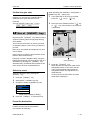
having the same frequency and same firing
times as those your boat has, the interference
noise may be displayed. If you set the
interference rejection, the interference noise
can be reduced. In the order of weak → strong,
the noise rejection capability becomes high.
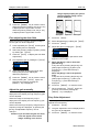
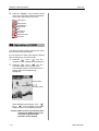
2.2 Change of Image
Speed
Image of school of fish
The image speed of echo sounder can be
changed. Even if the school of fish and bottom
are same, the image changes depending on the
image speed.
Interference image
The setting of image speed is shown by the
comparison with the normal image speed “1/1”.
“2/1” image speed is two times the normal
image speed. “1/2” is a half time the normal
image speed. When “Stop” is selected, the
image speed is stopped.
1
2
Press the 【MENU】 key.
3
Change the setting of [Image Speed].
4
Select the [Adjust] → [Image Speed].
OFF
Strong
1
Press the 【MENU】 key.
2
3
Select the [Adjust] → [Interference Rejection].
Change the setting of [Inference
Rejection].
Image speed
IR
2/1
1/1
Stop
1/1.5
1/2
1/2.5
1/3
1/3.5
1/4
1/4.5
OFF
Weak
Strong
Press the 【MENU】 key to close the menu
Weak
4
Press the 【MENU】 key to close the
menu.
2.4 Color Rejection of
Weak Echo
Color Rejection
2.3 Rejection of
Interference
Interference Rejection
The interference noise from the echo sounder
of other boats can be reduced.
If a neighboring boat uses the echo sounder
2-2
The color of weak echo can be rejected.
Rejecting noise on the entire image and weak
echo around the school of fish makes it easier
to see the school of fish. It is the convenient
function when displaying the echo stronger
than the specific signal. (setting:0~50%)
1
2
Press the 【MENU】 key.
Select the [Adjust] → [Color Rejection].
0093132702-01
CVS-126
3
Chapter 2 How to use the Menu
Change the setting of [Color Rejection].
Color Rejection
0 %
4
Setting of Fixed Shift
The scope of range starting with the shift value
is displayed.
Press the 【MENU】 key to close the
menu.
2.5 Rejection of Noise
Noise Rejection
The influence of noise can be reduced.
Due to echo reflected from plankton and dust,
the speck-like noise may appear on the entire
image. Setting the [Noise Rejection] reduces
the speck-like noise and makes it easier to see
the image of school of fish.(setting:0~10)
1
2
3
Press the 【MENU】 key.
2
3
Select [Adjust] → [Noise Rejection].
Change the set value of [Shift].
10
0~300
4
m
Press the 【MENU】 key to close the
menu.
Change the setting of [Noise Rejection].
Noise Rejection
5
4
Select [D. Range] → [Shift].
Shift
The greater the set value becomes, the
stronger the effect of noise rejection becomes.
1
Press the 【MENU】 key.
Press the 【MENU】 key to close the
menu.
Setting of Auto Shift.
The image is automatically shifted so that the
bottom is always displayed.
1
2
Press the 【MENU】 key.
3
Select the [Auto Shift].
Select [D. Range] → [Range Mode].
Range Mode
2.6 Setting of Shift
Manual
10
Auto Range
Auto Shift
The [Fixed Shift] and [Auto Shift] are provided.
Fixed Shift:
The image range is shifted up and
down.(setting:except ft:0~300,ft:0~1000)
4
Press the 【MENU】 key to close the menu.
[R: AS] is displayed at the upper side of
menu.
Auto Shift:
Since the bottom is always displayed in the
lower side, if the depth changes, the image is
shifted automatically. (In the depth direction)
2.7 Setting of Zoom Range
Set the zoom range in each mode of [BTM],
[Bottom Discrimination], [Zoom], [Bottom Zoom]
0093132702-01
2-3
Chapter 2 How to use the Menu
CVS-126
and [Bottom Follow Zoom]
Zoom start
10
The zoom range of each mode is identical.
0~800
(See [1.4 Switch-over of Menu].)
(setting:except ft:2.5~200,ft:10.0~650)
4
m
Press the 【MENU】 to close the menu.
2.9 Setting of Background
Color
Zoom Range
Responding to the ambient brightness, the
background color of display can be changed.
1
2
3
1
2
3
Press the 【MENU】 key.
Select [Display] → [Background Color].
Change the setting of [Background Color].
Background
Pale blue
Marine blue
Blue
Dark blue
Black
Pale gr. bl.
Gr. blue
Dark. Gr. bl.
White
Night mode
Select [D. Range] → [Zoom Range].
Change the set value of [Zoom Range].
Zoom Range
10.0
m
4
Press the 【MENU】 key.
Press the 【MENU】 key to close the
menu.
4
Press the 【MENU】 to close the menu.
2.8 Setting of Zoom Start
Select the zoom start in the [Zoom].
2.10 Setting of White Line
(See [1.4 Switch-over of Menu].)
(setting:except ft:0~800,ft:0~2800)
As the surface of bottom is marked with the
white line of constant width, the school of fish at
the bottom can be easily identified.
Zoom Start
White line
1
Press the 【MENU】 key
2
3
Select [Display Range] → [Zoom Start]
2-4
Change the set value of [Zoom Start].
1
Press the 【MENU】 key
0093132702-01
CVS-126
Chapter 2 How to use the Menu
2
Select [Disp] → [White Line].
3
Change the setting of [White Line].
“1” is narrowest. “5” is widest.
In the auto mode, responding to the
strength of echo reflected from the bottom,
the width of white line changes.
[Fish alarm] issues the alarm when an echo
recognized as school of fish exists in the set
range. (setting:except ft:0~800,ft:0~2800)
White line
OFF
1
2
3
4
5
Auto
4
It is convenient for you to judge whether the
echo of school of fish is present or not.
(setting:except ft:0~800,ft:0~2800)
Press the 【MENU】 key to close the
menu.
2.11 Preset of Range
The range switched with the 【 range 】 key
can be set.
Preset the set value suitable for you purpose.
(setting:except ft:0~800,ft:0~2800)
1
2
Press the 【MENU】 key.
3
Select the set value of [Range 1 to 8].
Select [Display Range] → [Range Preset]
→ [Range 1 to 8].
Range1
20.0
m
4
[Bottom alarm] issues the alarm when the
position recognized as the bottom is shallower
than the upper limit or deeper than the lower
limit. It is convenient when keeping the specific
depth.(setting:except ft:0~800,ft:0~2800)
Press the 【MENU】 key to close the
menu.
Caution: In the [Level], select the strength
of echo reflected from the school
of fish in the [Fish alarm].
[Water temp alarm] issues when the water temp
is within or out of the set range. It is convenient
to keep the specific water temp region.(setting:-5
~45℃,23~113ºF)
[Speed alarm] issues when the boat speed is
faster or slower than the set range. It is
convenient when the speed limit is
obliged.(setting:0~80)
[Arrival alarm] can be used in the state that the
destination is set. The alarm is issued when your
boat arrives within a certain range of destination.
A certain range is set in the [NAV alarm range].
(See [1.7 Use of 【Event】 key.)
[XTE alarm] can be used in the state that the
destination is set. The alarm is issued when your
boat is off a certain distance from the course on
the line drawn straightly from destination to the
location when setting the destination. A certain
distance is set in the [NAV alarm range].
In the [NAV alarm range], select the alarm
range of [Arrival alarm] and [XTE
alarm].(setting:10~999m)
Stopping the alarm sound
To stop the alarm sound and the alarm display,
press 【MENU】 key.
2.12 Setting of Alarm
6 alarms of bottom alarm, fish alarm, water temp
alarm, speed alarm, arrival alarm and XTE alarm
can be set.
They are notified by alarm sound and alarm
display.
0093132702-01
2-5
Chapter 2 How to use the Menu
Setting the alarm
Adjust
D.range
Image
Alarm1
Alarm2
NAV
Disp
Sonar
Next
Bottom alarm
Upper depth
Lower depth
OFF
5m
50m
Fish alarm
Position
OFF
5m
Range
Level
Return
50m
Medium
CVS-126
The set state of [Water temp alarm], [Speed
alarm], [Arrival alarm] and [XTE alarm] can be
confirmed by the icons at the upper side of
display.
[XTE alarm]
[Speed alarm]
[Arrival alarm]
[Water temp alarm]
[Bottom alarm]
Adjust
D.range
Image
Alarm1
Alarm2
NAV
Disp
Sonar
Next
Water temp warm OFF
Upper temp alarm 20.0 C
Lower temp alarm 15.0 C
Speed alarm
Speed limit
OFF
0kt
Arrival alarm
XTE alarm
NAV alarm range
Return
OFF
OFF
10m
1
2
Press the 【MENU】 key.
3
4
Select the [ON] of alarm you desire.
5
6
Change the set value of alarm range.
[Fish alarm]
Select your desired alarm from [Alarm 1] or
[Alarm 2].
If the setting of [Alarm range] is provided in
the alarm desired, select the alarm range.
Press the 【MENU】 key to close the
menu.
Release the alarm.
1
2
Press the 【MENU】 key.
3
4
Select the [OFF] of alarm to be released.
Select the alarm to be released from
[Alarm 1] or [Alarm 2].
2.13 Preset/ WPT edit/ WPT
delete of Destination
NAV Start.
The NAV can be started by selecting the
destination from the destination list.
To perform the NAV start, the destination must
be preset. (See [1.7 Use of 【Event】 key].)
1
2
3
Press the 【MENU】 key.
Select [NAV] → [NAV start].
Select the [Destination list] preset.
Close the menu with the 【MENU】 key.
Confirm the alarm state.
The set state of [Bottom alarm] and [Fish alarm]
can be confirmed on the bar at the right corner
of display. However, when the display is out of
the range, they are not displayed.
2-6
0093132702-01
CVS-126
Chapter 2 How to use the Menu
[WPT edit] list.
Caution: The list No. selected is reversed
in red.
4
After selecting the number, press the 【 】
key or the 【Knob】.
5
Select the [Yes] in the confirmation menu
and press the 【MENU】 key.
Then, the NAV starts.
4
After selecting the number, press the 【 】
key or the 【Knob】.
5
Select the character with the 【 】 key or
【 】 key. ( character: A~Z,blank,0~
9,+,-./)
6
Move the position of characters to be
reversed with the 【 】 key or 【 】key.
NAV starts
Yes
No
Cancel the NAV.
The NAV started can be canceled halfway.
1
2
3
Press the 【MENU】 key
Select [NAV] → [NAV cancel].
Press the [Yes].
NAV cancel
Yes
No
4
Press the 【MENU】 key. Then, the NAV is
released.
Edit the destination.
By entering the latitude and longitude, the
destination can be preset.
The list preset in the past can be edit.
1
2
3
Press the 【MENU】 key.
Select [NAV] → [WPT edit].
Select the list No. to be edited from the
0093132702-01
Caution: At this moment, if the [Knob] is
2-7
Chapter 2 How to use the Menu
pressed, the setting is cancelled
and the menu returns to the
menu item.
Caution: If the values of latitude and
longitude are abnormal or are
not entered, they cannot be
preset.
7
8
After finishing the edit work, press the
【MENU】 key.
Select the [Preset] in the confirmation
menu and press the 【MENU】 key. Then,
the edit is finished.
Edit is finished
Yes
No
CVS-126
Caution: If the 【Knob】
】 is pressed at this
moment, it is canceled.
6
Recall the image stored and preset it
as a destination.
Call the image stored in the past and it can be
preset as a destination. (See [1.7 Use of
【Event】 key].)
1
Press the 【MENU】 key.
2
3
Select [NAV] → [Image recall].
Delete the destination.
No.
1
2
3
4
5
6
7
8
9
10
The deletion takes some time.
Press the 【MENU】 key.
Select [NAV] → [WPT delete].
Select the list number of destination to be
deleted from the [WPT delete].
4
5
4
After selecting the number, press the 【 】
key or the 【Knob】.
5
Select the [Yes] in the confirmation menu
and press the 【MENU】 key.
Then, the destination is deleted.
Select the image No. from the [Image
recall] list.
Image recall
The destination list preset in the past can be
deleted.
1
2
3
Press the 【MENU】 key. Then, the
destination is deleted and the menu closes.
Comment
PIC00001
PIC00002
PIC00003
PIC00004
PIC00005
PIC00006
PIC00007
PIC00008
PIC00009
PIC00010
Press the 【 】key or the 【Knob】.
Move the cursor to the location preset as a
destination with the【 】key or 【 】 key
and select it.
Destination is delete
Yes
No
2-8
0093132702-01
CVS-126
Chapter 2 How to use the Menu
H
L
5
When the echo sounder image to be stored
appears, press the 【EVENT】 key.
6
When the image store is fully filled, it
shows that the [Store image] is fully filled.
After deleting the unwanted image, try it
again.
Recall the stored image.
The image stored in the past can be recalled.
During recalling, the image cannot be stored.
1
2
Press the 【MENU】 key.
3
Select the number of image to be recalled
from the [Image recall] list.
Select [NAV] → [Image recall].
Cursor(red line)
Image recall
No.
1
2
3
4
5
6
7
8
9
10
Caution: You can switch to other stored
image with the 【 】 or 【 】 key.
6
When starting the NAV, press the
【EVENT】key.
7
When you do not start the NAV, press the
【MENU】 key.
Comment
PIC00001
PIC00002
PIC00003
PIC00004
PIC00005
PIC00006
PIC00007
PIC00008
PIC00009
PIC00010
2.14 Store/Recall/Deletion
of Image
4
After selecting the number, press the 【 】
key or 【Knob】 to enter.
Store the image.
5
Press the 【MENU】 key to return to the
normal menu.
The present image of echo sounder can be
stored.
Caution: When other stored image exists
beside the recall image, switch
to other image with the 【 】 and
【 】 key.
To memorize, it takes some time.
To memorize the image, the 【EVENT】 key
must be switched to the [Store image].
1
2
3
Press the 【MENU】 key.
Select [NAV] → [EVENT key set].
Delete the stored image.
Select the [Store image].
The image stored in the past can be deleted.
To delete, it takes some time.
EVENT key set
Store pos
Store image
Homing
4
Press the 【MENU】 key to close the
menu.
0093132702-01
1
2
3
Press the 【MENU】 key.
Select [NAV] → [Image delete].
Select the number of image to be deleted
from the [Image delete] list.
2-9
Chapter 2 How to use the Menu
CVS-126
4
Image delete
No.
1
2
3
4
5
6
7
8
9
10
4
5
Comment
PIC00001
PIC00002
PIC00003
PIC00004
PIC00005
PIC00006
PIC00007
PIC00008
PIC00009
5
No.
Comment
1
P I C00001
2
P I C00002
P I C00003
3
6
After selecting the number, press the 【 】
key or 【Knob】 to enter.
Select the comment position with the 【 】
key or 【 】 key.
Image comment
No.
Comment
1
P I C00001
2
P I C00002
P I C00003
3
Select the [Yes] in the confirmation menu
and press the 【MENU】 key.
Then, the preset image is deleted.
Caution: At this moment, if the 【Knob】
】 is
pressed, the setting is cancelled
and the menu returns to the
menu item.
Confirm image
Yes
No
7
After finishing the edit, press the 【MENU】
key.
8
Select the [Register] in the confirmation
menu and press the 【MENU】 key. Then,
the edit is finished.
It is convenient to judge the stored image.
1
2
3
Select the character with the 【 】 key or
【 】 key.( character: A~Z,blank,0~
9,+,-./)
Image comment
PIC00010
Add the comment to the stored
image.
After selecting the number, press the 【 】
key or the 【Knob】.
Edit is finished
Register
Not register
Press the 【MENU】 key.
Select [NAV] → [Image comment].
Select the number of image to which the
comment is added from the [Image
comment].
2.15 Selection of Zoom
Image comment
No.
1
2
3
4
5
6
7
8
9
10
2-10
Comment
PIC00001
PIC00002
PIC00003
PIC00004
PIC00005
PIC00006
PIC00007
PIC00008
PIC00009
Set the zoom display with the display mode
([zoom (H)] or [zoom (L)].
The [Bottom], [Bottom Discrimination], [Zoom],
[[Bottom Zoom] and [Bottom Follow Zoom] are
provided. (See [1.4 Switch-over of Menu].)
1
Press the 【MENU】 key.
2
3
Select [Display range] → [Zoom image].
Select the zoom image.
PIC00010
0093132702-01
CVS-126
Chapter 2 How to use the Menu
Zoom select
display1
BTM.
B.D.
Zoom
B.Z.
B.F.Z.
RNG
HDG
BRG
display2
Water temp
The time required
Course
Wind dir.
display3
display4
4
Press the 【MENU】 key to close the
menu.
XTE
For each zoom display, refer to [1.4 Switch-over
of display].
Boat speed
Lat/Lon
Wind speed
Depth
2.16 Selection of NAV
Display
The information can be displayed on the NAV
display (NAV 1, NAV2).
Information to be displayed in 1 to 4
Wpt dist dir., Time required, Wind dir., Wind
speed, depth, Lat/Lon, Boat speed, course,
water temp, Heading and XTE
Type of NAV Display
Dividing Method of Display
Depending on the division method (2 division, 4
division), the information to be displayed differs.
1
2
3
2 division
Press the 【MENU】 key.
Select [Display] → [NAV 1] → [NAV 2].
Select the dividing method (2 division, 4
division).
NAV1
display1
2
4
4
display2
Press the 【MENU】 key to close the
menu.
Simple plotter
Selection of NAV Menu
Speed meter
1
Press the 【DISP】 key.
2
Select the [NAV1/Normal (H)] or the
[NAV2/Normal (L)].
3
Press the 【 】key.
The [NAV1 display1] is displayed.
Compass
NAV display1
Simple Plotter
Information displayed in 1 and 2
Simple plotter, speed meter and compass
4 division
0093132702-01
4
5
Select by rotating the 【Knob】.
To change the [NAV 2], press the 【 】
2-11
Chapter 2 How to use the Menu
key.
Caution: Every time when pressing the
【 】 key, the [Display] switches
in the order of [NAV1] to [NAV4].
6
7
Select the [NAV] by rotating the 【Knob】.
Press the 【MENU】 key to close the
menu.
2.17 Explanation of Sonar
Switch-over of Sonar Tone
The sonar can be outputted to the built-in
speaker by selection.
The school of fish and condition of bottom on
the display of echo sounder can be confirmed
by hearing the sonar.
Sonar tone
OFF
ON
1
2
3
Press the 【MENU】 key.
Select the [Sonar] → [Sonar tone].
Select the [ON] or [OFF] of Sonar tone].
Caution: When set to [OFF], the built-in
speaker does not output the
sonar.
When set to [ON], the built-in
speaker outputs the sonar.
4
Press the 【MENU】 key to close the
menu.
CVS-126
2.18 Explanation of Menu
Item
The various items in the menu are explained.
TVG
The TVG corrects the difference of strength
between echo reflected from the shallow depth
and echo reflected from deep depth so that the
reflection can be uniformed.
The deeper the depth is, the weaker the
reflected signal of echo sounder becomes due
to attenuation. Thus, comparing with the signal
reflected from the same size fish in the shallow
depth, the signal reflected from the fish in the
deep depth becomes weak. The TVG corrects
the echo signal reflected from the deep depth to
be equal to that reflected from shallow depth by
increasing the receiver gain so that the effect
that the strength of echo signal reflected from
the deep depth looks same as that reflected
from the shallow depth provided. The correction
gain due to the depth increases in the order of
weak → medium → strong. When set to “weak”,
the TVG also provides the effect that reduces
noise in the shallow depth.
1
2
Select the [Adjust] → [TVG].
Select the [weak, medium, strong].
TVG
Weak
Medium
Strong
Connection of External Speaker
Change the TX power.
Connect the external speaker with amplifier
(option) so that you can hear the sonar easily.
The strength of transmission output (power)
can be changed.
The sonar is always outputted. Adjust the
speaker volume with the volume provided on
the speaker.
When the noise of interference with the
neighboring echo sounder occurs, if the powers
of transmission outputs at both sides are
weakened, the interference noise can be
suppressed.
Caution: The external speaker is an option.
In the [Auto] setting, the transmission output is
automatically adjusted.
2-12
0093132702-01
CVS-126
Adjust
D.range
Image
Alarm1
Alarm2
NAV
Disp
Sonar
Next
Chapter 2 How to use the Menu
Image speed
IR
Color Rejection
1/1
Strong
0%
Noise Rejection
Clutter
0.0
5
TGV
TX power
Return
Medium
Auto
1
Select the [Display] → [A scope].
2
To display the A scope, select the [ON].
To stop the display of A scope, select the
[OFF].
Change the display color of echo
sounder image
The [Monochrome], [8 color], [16 color] and [64
color] can be selected.
1
2
Select the [Adjust] → [TX power].
When selecting the smaller number, the
transmission power becomes weak.
TX power
1
2
Select the [Display] → [Color tone].
Select the [Color tone].
Change the depth value.
20
1
30
40
50
60
70
80
90
100
Auto
The display size of depth value and the scale
value can be changed.
1
Select the [Display] → [Depth display].
2
Select the size of display.
Display the water temp graph. / Stop
the display of water temp graph.
The latest water temp value and the graph of
past water temp data can be displayed.
Display the A scope. / Stop the
display of A scope.
The echo strength of latest echo can be
displayed at the right side of echo sounder
display.
1
Select the [Display] → [Water temp graph].
2
To display the water temp graph, select the
[ON].
To stop the display of water temp graph,
select the [OFF].
The strength of echo sounder image is
expressed by the horizontal width. This
expression is called [A scope].
The width for strong echo is wide and the width
for weak echo is narrow. This makes it easier
for you to see the echo.
Adjust
D.range
Image
Alarm1
Alarm2
NAV
Disp
Sonar
Next
Disp Width
When the image is zoomed or the high
frequency/low frequency displayed, the disp
width can be changed.
A scope
White line
OFF
OFF
Background color Marine blue
Color tone
Depth value
64 color
Large
Water temp graph OFF
Return
0093132702-01
2-13
Chapter 2 How to use the Menu
Adjust
D.range
Image
Alarm1
Alarm2
NAV
Disp
Sonar
Next
1
2
Disp width
Image swap
NAV 1
NAV 2
Return
CVS-126
Center
A B
2
4
Select the [Disp] → [Disp. width].
Select the width of image.
Image Swap
The images of echo sounder at the right and left
sides can be swapped.
1
2
Select the [Display] → [Image swap].
Select the swap state.
2-14
0093132702-01
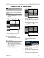
Chapter 3 How to use the system menu
CVS-126
Chapter 3 How to use the system menu
3.1 Display of System Menu
After powering on, besides the menu displayed
first with the 【MENU】 key, the system menu, of
which setting is not frequently changed, is
provided.
[In out],[Correct],[System],[Setting],[Maintain]
Display the system menu
1
Press the 【MENU】 key.
2
Select the [Next].
Adjust
D.range
Image
Alarm1
Alarm2
NAV
Disp
Sonar
Next
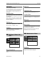
3.2 Setting of External
In/Out
Set the setting related to the input/output.
Prev
In out
Correct
System
Setting
Maintain
Buzzer Setting
Temp source
OFF
Sensor
Speed source
Sensor
Baud rate
NMEA monitor
4800
OFF
NMEA output data
Return
In out
Correct
System
Setting
Maintain
Buzzer Setting
Set the buzzer sound to ON/OFF.
Temp Source
3
Press the 【 】 key to display the system
menu.
Switch the Sensor/NMEA.
Use the built-in water temp meter for sensor.
Prev
In out
Correct
System
Setting
Maintain
Adjust
Use the external input value for NMEA.
D.range
Image
Alarm1
Alarm2
NAV
Disp
Sonar
Speed Source
Switch the Sensor/NMEA.
Use the built-in speed meter for sensor.
Use the external input value for NMEA.
Baud Rate
Return to the normal menu.
1
Select the [Prev].
2
Press the 【 】 key to display the normal
menu.
0093132702-01
Change the transmission speed of external
input/output.
Match the transmission speed with that of
external equipment connected.(setting:
4800,9600,19200,38400)
3-1
CVS-126
Chapter 3 How to use the system menu
NMEA Monitor
Draft Set
The external input data can be displayed.
The tolerance of depth can be corrected.
To return to the original menu, press the
【MENU】 key.
Set the depth from the sea level to the set depth
of your transceiver/receiver. Normally set draft
value of your boat.(setting: expect ft:-10.0~
10.0,ft:-30.0~30.0)
NMEA Output Data
The output of NMEA sentence can be set to
ON/OFF.
Sonic Speed
1
Select the sentence name.
Set the [Seawater] or [Freshwater].
Change to meet the usage,
2
Press the 【 】 key.
Prev
In out
Correct
System
Setting
Maintain
Water Temp
Prev
DBT
ON
DPT
ON
GGA
MTW
OFF
OFF
TLL
ON
VHW
VTG
OFF
OFF
Boat Speed
ZDA
OFF
The tolerance of boat speed value can be
corrected.
Return
The error of water temp value can be corrected.
(setting:-10.0~10.0℃,-10~10°F)
When the [Speed source] is set to the [Sensor], it
is corrected by %. (setting:-50~50%)
3
4
Select the ON/OFF.
5
Press the 【 】 key.
Select the [Prev].
Caution: If you omit steps 4 and 5, the
setting is valid. But, when
selecting the [In out] menu next,
the [NMEA out data] is displayed.
When the [Speed source] is set to the [NMEA], it
is corrected by numeral. (setting:-10.0~10.0)
Inner-hull
The signal attenuation value in inner-hull use can
be adjusted.(setting:-10~10: through-hull:0)
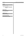
3.3 Setting of Correct Item
3.4 Setting of System Item
Prev
In out
Correct
System
Setting
Maintain
Draft set
Sonic speed
0.0m
Water temp
0.0 C
Boat speed
0%
Inner-hull
0
Return
3-2
Seawater
Prev
In out
Correct
System
Setting
Maintain
Simple menu
Operation Guide
OFF
ON
FUNC.key setting Image speed
Language
Return
English
0093132702-01
Chapter 3 How to use the system menu
CVS-126
Simple Menu
Depth Unit
Set the simple menu display.
It switches the unit of depth to fm, l.fm and ft.
The items displayed in the menu are limited only
to the setting items of minimum requirement.
When making the setting change fewer, it is
convenient.
Temperature Unit
It switches the unit of temperature to °C, °F.
Operation Guide
When displaying the menu, it sets whether or not
the operation guide is displayed at the lower part
on the display.
Location Offset
The location offset can be set by 0.5 hours (30
minutes) unit.(setting:-11.0~14.0h)(UTC:0.0)
When setting to “No display of operation guide”,
the echo sounder image can be easily seen at
the menu operation.
GPS select
FUNC key set
It selects whether the GPS sensor is the KODEN
made one or not.
Set the function assigned to the 【FUNC】 key.
(See [1.8 Use of 【FUNC】 key].)
GPS initialize
It is valid only when KODEN GPS is connected.
Language
The GPS sensor is initialized.
Switch to the language to be displayed.
When connecting the GPS sensor other than
KODEN GPS, do not use this item.
(See [1.2 Power On/ Off ].)
3.5 Setting of Basic Set
Item
3.6 Maintenance Menu
Prev
In out
Correct
System
Setting
Maintain
Simulation
Initialize
OFF
No
System check
All WPTs:DLT
All IMG DT:DLT
Return
Simulation
Range & Speed Unit
When the [Simulation] is set to ON, the pseudo
image of echo sounder is displayed.
It switches the display unit to [nm, kt] or [km,
km/h].
0093132702-01
3-3
CVS-126
Chapter 3 How to use the system menu
Initialize
It returns all the settings in the menu to the
factory settings. However, the memorized data of
display remains unchanged.
Caution: It returns to the factory settings
and the power is automatically
shut down.
System Check
It is used for diagnostic test.
(See [4.5 Diagnostic Test ].)
All WPTs deletes
All WPT lists can be deleted.
All stored image deletes
All stored image lists can be deleted.
3-4
0093132702-01
Chapter 4 Maintenance and Inspection
CVS-126
Chapter 4 Maintenance and Inspection
4.1 Inspection
The daily maintenance and inspection extends the life of equipment. To always keep the equipment in
the best condition, implement periodically the inspection shown in the table below.
Item
Content of Inspection
Connector at the rear of
CVS-126 Display unit
Check the looseness.
Wiring of cables
Check the wiring of cables connecting the equipment and the
damage of cable.
Grounding of display unit
Scrape the rust off the ground terminal and make its contact well.
4.2 Cleaning
CVS-126 Display unit
To protect the LCD and enhance the visibility of display, the acrylic filter is installed to the surface of
CVS-126 Display unit. If this part is dirty, an image becomes unclear. So, dip the soft cloth in the neutral
or alcohol detergent and wipe the filter surface lightly with the cloth wrung lightly.
Caution
Thinner
NEVER use a thinner solvent. If done so, the filter
surface will chemically decompose, resulting in
of transparency.
Transducer
In case of through-hull equipped transducer, check the surface of opening of transducer (portion form
which the ultra-sonic is emitted). If shells and oil are stuck, scrub the surface with a wooden or bamboo
knife with caution not to damage the surface and remove stuck matters. If you scrub strongly, the
surface will be damaged, resulting in deteriorated performance of transducer.
4.3 Fuse Replacement
Warning
Use the specified fuse. If you use a fuse other than
specified one, it may lead to a serious accident.
If the input voltage is too high, the over-current flows or a trouble occurs inside, the fuse will blow out.
The fuse is housed in the power cable.
0093132702-01
4-1
CVS-126
Chapter 4 Maintenance and Inspection
4.4 If you suspect a trouble
Symptom
Trouble cause
Countermeasure
Even if the power is
powered on, nothing is
displayed.
• Blown fuse.
• The power voltage is out of
specification (10.8 to 31.2
VDC).
• Poor connection between
power cable and battery.
• Exchange a fuse.(See [4.3 Fuse
Replacement])
• Use a proper power as per
specification.
• Confirm a connection between the
power cable and the battery.
The unit starts up. But,
nothing is displayed on
the display.
• Connection between
transducer and display unit.
• Defect of LCD display block.
• Confirm a connection between
Transducer and Display unit.
• Consult a repair shop or the
distributor in your market.
Too much interference
and noise.
• Installed position of
transducer.
• Interference from the echo
sounder on other boat.
• Confirm the position of transducer.
(See [5.3 Installation of
Transducer])
• Apply the interference rejection.
(See [2.3 Rejection of
Interference])
The display of water
temperature / boat speed
is abnormal or not
displayed.
• Connection of sensor
connector.
• Input source of water
temperature sensor / speed
sensor.
• Confirm the connection of the sensor
connector.
• Confirm the input source.
The display of present
location/course is
abnormal or not
displayed.
• Connection between this unit
and navigation equipment.
• Confirm a connection between
Display unit and the navigation
equipment.
4-2
0093132702-01
Chapter 4 Maintenance and Inspection
CVS-126
4.5 Diagnostic Test
Perform the operation diagnosis.
When checking the operation diagnosis of panel
key, the state of sensor inside and the version of
software, it is using.
Return to the normal menu.
Press the 【MENU】 key for more than 3
seconds.
①
ROM
RAM
NM EA
OK
VOLT
T EMP
S PEED
NG
②
GAIN
③
KM-E67 Ver1.00 20080408
FishSnd ver01.00 Jan 23 2008 09:18:54
Ipl
ver01.00 Jan 24 2008 15:21:33
SimData ver01.00 Jan 24 2008 15:21:33
TOP.ncd 3s400ft256 2008/03/26 14:38:31
Diagnose.
① displays the diagnostic result.
The result of ROM and RAM check displays OK
when normal and NG when abnormal.
Caution: To test the NMEA, TEMP and
SPEED, the special jig is
necessary.
② implements the key input test. When pressing
the key, the color of a part corresponding to the
pressed key changes.
When pressing the [Knob], the LCD test is
performed.
Confirm the version.
③ displays the information on the version of
software.
When inquiring, inform us of verXX.XXX.
0093132702-01
4-3
Chapter 5 Installation
CVS-126
Chapter 5 Installation
5.1 Item of Caution on Installation
To exercise fully the performance of echo sounder, the installation of CVS-126 must be performed by
an engineer who is officially authorized by our company. The installation work includes the following
content.
(1) Unpacking the configuration items
(2) Inspection of configuration unit, spare, accessories and material for installation
(3) Check of power voltage and capacity of current
(4) Decision of installing location
(5) Installation of CVS-126 Display unit and transducer
(6) Installation of accessories
(7) Plan and execution of cable laying and connection
(8) Adjustment after completion of installation
Unpacking the configuration parts
Unpack the configuration items and confirm that all of the items match with the contents on the
equipment configuration list. If not matched, Contact the dealer you purchased or our sales company.
Inspection of configuration items and accessories
Inspect the appearance of each configuration item and accessories and check that no dents or
damage exist.
If any dents or damage exists and they are believed to be caused by accident during transportation,
contact the transportation and insurance company and consult our sales company or our dealer
nearest to you.
Decision of Installing Location
To exercise fully the performance of equipment, install the equipment, considering the points
mentioned below.
(1) Install the equipment at the location in the bridge so that its display can be easily seen.
(2) Select a safe location where the equipment is not exposed to humidity, water splash, rain and
direct sunshine.
(3) Keep enough space for maintenance. Especially, secure enough space at the rear panel where
many cables are concentrated.
(4) Keep the equipment as far away from the wireless transmitter/receiver as possible.
5-1
0093132702-01
CVS-126
Chapter 5 Installation
The equipment is not waterproofed. Avoid excessively damp place. Do not
install the equipment in place suffering from excessive water-drops.
Otherwise, the inside of display window mists over or corrosion may occur
inside.
Laying and Connection of Cable
(1) Keep the transducer and power cable as far away from the cables of other electronic equipment
as possible.
(2) The cabinet of CVS-126 Display unit is securely grounded to the hull, using the ground terminal on
the rear panel.
Caution: The ground side of power input of this equipment is connected to the ground
terminal.
In case of + (positive) ground, it cannot be used. The power may short-circuit.
(3) If you connect the power cable directly to the battery, the interference from other electronic
equipment is not subject to occurrence. (See Fig. 5.1.)
CVS-126 Display unit
Good example
CVS-126 Display unit
Bad example
Battery
Battery
Noise
Noise
Fig. 5.1 Connection of Power Line
Confirmation after Installation
Be sure to confirm the following items before starting up this equipment. The confirmation is mandatory
to operate the equipment normally.
(1) Is the power voltage in the boat within the appropriate voltage range? Is the current capacity
enough?
Voltage Range: 10.8 to 31.2V when measured at the power connector input.
(2) Is the wiring of transducer cable correct? Is the wiring shorted?
5.2 Installation of CVS-126 Display unit
CVS-126 Display unit can be desk-top installed or flush-mount installed.
It cannot be installed in other method (Example: Suspended installation). Install in the following
procedure.
0093132702-01
5-2
Chapter 5 Installation
CVS-126
Desk-top Installation
(1) Loosen the knob bolt fixing CVS-126
Display unit to the mounting bracket, push
the unit to the left side and pull the unit
upward.
CVS-126 Display unit
Knob bolt
Turn two turns the knob bolt to
loosen it and pull the unit upward.
Fixing screw
4
(2) Place the removed unit to a safe and flat
place.
(3) Place the mounting bracket on the location
for the unit to be installed and fix it with
four screws (trans-tapping screws)
supplied with installing materials.
(4) Connect the connectors for power and
transducer to the unit respectively.
Mounting bracket
Fig. 5.2 Desk-top Installation
(5) Install the unit to the mounting bracket and
fix the unit by turning clockwise the knob
bolt
Flush-mount Installation
(1) Make a square hole (160mm x 160mm) at the location to be installed. (See Fig. 5.4.)
(2) Turn counter-clockwise the knob bolt fixing CVS-126 Display unit to the mounting bracket to
loosen it, push the unit to the left side and pull the unit upward. The mounting bracket and knob
bolt are no longer used.
(3) Confirm that the unit matches with the square holes. If not matched, correct the square hole.
(4) Remove the front frame of CVS-126 Display unit, pulling it toward you. (See Fig. 5.3.)
(5) Connect the connectors for power and transducer to the unit respectively.
(6) Install the CVS-126 Display unit in the installing location (square hole) and fix it with four tapping
screws (4mm) (M4 or pan-head). (Prepare 4mm screws suitable for thickness of installing
location.)
(7) Install the front frame removed in step (4).
5-3
0093132702-01
CVS-126
Chapter 5 Installation
Threading hole
160 16
R30
Fixing screw 4mm
Not supplied
4 pieces
Front frame
Figure 5.3
Flush-mount Installation
Figure 5.4 Work of flush-mount installation hole
0093132702-01
5-4
Chapter 5 Installation
CVS-126
5.3 Installation of Transducer
The standard installation of this echo sounder is shown in figure 5.5.
Figure 5.5 Installation of Transducer
In case of Inner-Hull
Using the optional inner-hull kit (MFB-04), install the transducer to the inner side of ship’s bottom.
Caution on installation
Figure 5.6 Inner-Hull Installation
(1) Select the location where no bubble is generated during navigation.
(2) Select the relatively thin location of ship’s bottom.
(3) Be sure to remove oil on the contact surface. File the contact surface with sand paper (#400) so
that the adhesive strength will increase.
(4) The adhered surface will dry in about two hours.
(5) Leave the unit for a whole day and fill in the coolant. More than 80% of the transducer should be
submerged in the coolant.
5-5
0093132702-01
CVS-126
Chapter 5 Installation
In case of through hull
Install the transducer directly to the ship’s bottom
Installation Procedure
(1) Select the installing location.
(2) Remove the fixing nut and one piece of rubber packing.
(3) If the slope of ship’s bottom is greater than 5°, make a wooden base to fit to the slope of ship’s
bottom. To reduce the water resistance, cut the bow direction tip of wooden base at the outer side
of ship’s bottom in the triangle shape.
(4) Make holes at the installing location. If the wooden base is used, make holes in the wooden base.
(5) Thread the rubber packing in the transducer and then the cable.
(6) To prevent water from seeping through the gap between the transducer and the hole, fill out the
gap with FRP or silicon glue. (Glue the wooden base likewise.)
(7) Thread the rubber packing and fix it with the fixing nut firmly.
(8) Connect the transducer cable to the connector of CVS-126 Display unit.
Fixing nut
Rubber packing
Fixing nut
Rubber packing
Wooden base
Ship,s bottom
Wooden base
Rubber packing
Transducer
Rubber packing
Transducer
Less than 5
In case that the slope of ship,s bottom is less than 5
,
Ship s bottom
In case that the slope of ship,s bottom is greater than 5
Figure 5.7 Through-hull Installation
0093132702-01
5-6
Chapter 5 Installation
CVS-126
5.4 Wiring
Connection of Cable to CVS-126 Display unit
Connect the power cable and transducer to the connectors of CVS-126 Display unit.
POWER
Power input
10.8~31.2VDC
NMEA data input output
GPS, plotter etc
Sonar tone output
Line output for speaker with amplifier
Power output
For power of GPS etc
TD
Transducer
For 50/200kHz in common
Speed sensor data input
Water temperature sensor data input
GND
Pin Assignment of Rear Connector
Pin assignment viewed from the rear of CVS-126 Display unit.
POWER
5-7
Sonar tone R
Sonar tone L
Power +
GND
NMEA TXNMEA TX+
NMEA RX+
NMEA RXPower Shield
Sonar tone COM
Outside power
TD
Speed sensor input
Speed sensor power
Transducer input output
Transducer shield
Transducer input output
Water temperature sensor power
Water temperature sensor input
Speed sensor GND
0093132702-01
CVS-126
Chapter 5 Installation
Connection of Power Cable and Transducer
Connect the power cable to the [POWER] connector and the transducer to the [TD] at the rear of
CVS-126 Display unit connector.
Connection of DC power cable (CW-264-2M)
3.5 stereo jack
To [POWER] connector
DC+ (Red)
DC- (Black)
Caution: Wind the insulation tape around the un-used lead wire for core-wires not to contact
each other.
Connection of transducer
To [TD] connector
Grounding
• Use heavy gauge cable for grounding wire.
• Connect the grounding wire to the grounding material in a short distance.
• When connecting the external equipment of which positive polarity is connected to the ground line,
do not connect the ground of signal line to the cabinet ground.
Connection with external equipment
The DC power cable contains the connection cables for external equipment such as navigation
equipment and KODEN GPS sensor.
Color
Pin
Remark
Red
③
Power input+ (with 2A fuse)
Black
⑨
Power input- (with 2A fuse)
Orange
⑥
NMEA data output +
Blue
⑤
NMEA data output -
White
⑦
NMEA data input +
Green
⑧
NMEA data input -
0093132702-01
Color
Pin
White
②
Red
①
Black
⑪
Remark
External speaker output
(with ø3.5 stereo jack)
Yellow
⑫
Outside power
Gray
④
GND
Shield
⑩
5-8
Chapter 5 Installation
CVS-126
Connection with Speed Sensor or Water Temperature Sensor (Option)
When installing the optional speed sensor or water temperature sensor, connect to the [TD] connector
together with the transducer via the transducer cable (Type: CW-840-0.3M). For wiring, see the figure
below.
After soldering, implement the waterproof and insulation treatment on the connected part with the
self-melting tape.
Structure of Transducer Cable
TD1 (Orange)
2 core shield wire
Shield
TD2 (White)
SPD.PULSE (Blue)
SPD.VCC (Violet)
To the speed sensor
SPD.GND (Black)
lead wire
TEMP.VCC (Green)
TEMP.SIG (Red)
To the water temperature sensor
Connection Table of Transducer
Transducer Cable
No. of 2 core shield
Color of 2 core shield
3
4
5
Orange
Shield
White
Transducer
TD-500T-2
TD-500T-3
Red
Shield
White
Connection Table of Speed Sensor and Water Temperature Sensor
Transducer Cable
5-9
Water Temperature Sensor / Speed Sensor
No, of lead
wire
Color of lead
wire
T-81
ST-80
ST-80-1
ST-90
ST-90-1
ST-100
ST-100-1
1
Blue
—
Green
Green
Green
2
Violet
—
Red
Red
Red
6
Green
Gray
White
White
White
7
Red
Gray
Brown
Brown
Brown
8
Black
—
Shield
Shield
Shield
0093132702-01
CVS-126
Chapter 5 Installation
Connection of External Speaker (Prepared by a customer)
The ø3.5 stereo jack is provided to the power cable.
If you connect the speaker with the amplifier to the external, you can clearly hear the sonar sound.
Adjust the volume of speaker with the amplifier equipped to the speaker
3.5 stereo jack
5.5 Serial Data
Input Data
The sentences of GGA, GLL,HDT, MTV, MWV, RMC, VHW, VTG and ZDA can be received.
The type of NMEA0183 Ver.1.5, Ver.2.0 and Ver.3.0 can be inputted.
Information
Latitude,
Longitude
Course
Haedding
Ground Speed
Water Speed
Priority Order of Sentence
GGA>RMC>GLL
Information
Wind Direction
Priority Order of Sentence
MWV
VTG>RMC
HDT
VTG>RMC
VHW
Wind Speed
Date
Time
Water
Temperature
MWV
ZDA>RMC
ZDA>GGA
MTW
Output Data
The sentences of DBT, DPT, GGA, GLL, HDT,MTW, MWV,RMC, TLL, VHW, VTG and ZDA can be
transmitted.
The output is performed in the type of NMEA0183 Ver.2.0. However, the DBT is performed in Ver.1.5.
Sentence
DBT
DPT
Information
Depth
Depth from the transducer
Sentence
MWV
RMC
GGA
GLL
HDT
MTW
Latitude/Longitude, Time
Latitude/Longitude
Headding
Water Temperature
TLL
VHW
VTG
ZDA
0093132702-01
Information
Wind Direction, Wind Speed
Latitude/Longitude, Course,
Ground Speed, Date
Target Position
Water Speed
Course, Ground Speed
Date,Time
5-10
Chapter 6 Table Attached
CVS-126
Chapter 6 Table Attached
6.1 Menu List
The factory set value is shown by the bold and underline.
6-1
0093132702-01
CVS-126
Chapter 6 Table Attached
,Homing
Inner-hull (-10~10:0)
GLL
HDT
MWV
RMC
Other KODEN GPS
All WPTs:DLT
All IMG DT:DLT
0093132702-01
6-2
Chapter 6 Table Attached
CVS-126
6.2 Specification
Serial
Data
Indicator
Overall
Item
Model
Transmission
Frequency
Transmission
Method
Transmission
Power
Condition
Environment
Single or alternate
600W
Transmission
Firing Times
Transmission
Pulse Width
Minimal
Reception Gain
Display
Display Mode
Zoom Mode
5.7 inch color TFT LCD QVGA
Normal, dual frequency, zoom, NAV (homing mode, compass), A scope, tide
Bottom, bottom discrimination, zoom, bottom zoom, bottom follow zoom
Range
Range Unit
Shift Amount
Zoom Range
Image Speed
Function
Registration
Color tone
Input Data
2.5 to 800m (It can be set at arbitrary 8 locations.)
m, fm, l.fm, ft
0 to 300m (Maximum depth 1200m using Shift)
2.5m to 200m
10 stages (2/1, 1/1, stop, 1/1.5, 1/2, 1/2.5, 1/3, 1/3.5, 1/4, 1/4.5)
Image speed, range method, shift, interference rejection, color rejection,
noise rejection, zoom range, zoom depth, white line, background color
Monochrome, 8 color, 16 color, 64 color
Type NMEA0183 Ver.1.5/2.0/3.0
Output Data
Power
6-3
Content
CVS-126
50kHz/200kHz
5000 times/minute at maximum
50µs to 30ms
0dBµV
GGA, GLL, MTW, MWV, RMC, VHW, VTG, ZDA
Type NMEA0183 Ver.2.0 (DBT only Ver.1.5)
DBT, DPT, GGA, GLL, MTW, RMC, TLL, VHW, VTG, ZDA
DC10.8—31.2V 10W
Range of
Operating
Temperature
Upper limit of
Store
Temperature
-15°C to +55°C
Upper limit of
humidity
Waterproof
93% ± 3% (At +40°C)
Vibration
Resistant
+70°C
IPX5
Size of Cabinet
When the following vibration is applied to equipment respectively under
specified condition, its performance should not be affected.
• From 2 - 5Hz up to 13.2Hz vibration width ±1mm ±% (Maximum
2
acceleration 7m/s constant at 13.2Hz)
2
• From 13.2Hz up to 60Hz Maximum acceleration 7m/s constant
Maximum 182x208x130 (Unit 182x182x85)
Weight
1.3kg
0093132702-01
CVS-126
Chapter 6 Table Attached
6.3 Appearance
0093132702-01
6-4
Chapter 6 Table Attached
6-5
CVS-126
0093132702-01
11001 Roosevelt Blvd., Suite 800
St. Petersburg, FL 33716
Tel: 727-576-5734
Fax: 727-576-5547
Website: www.kodenamerica.com