1
table of contents
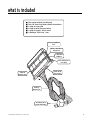
What Is Included . . . . . . . . . . . . . . . . . . . . . 3
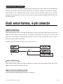
Shock Sensor Harness, 4-Pin Connector . . . . . 23
Installation Points to Remember . . . . . . . . . . 4
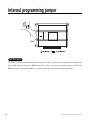
Internal Programming Jumper . . . . . . . . . . . 24
Light Flash Jumper . . . . . . . . . . . . . . . . . 24
Deciding on Component Locations
Siren . . . . . . . . . . . . . . . . . .
Control Module. . . . . . . . . . . .
Shock Sensor . . . . . . . . . . . . .
Valet/Program Switch . . . . . . .
Status LED . . . . . . . . . . . . . .
Starter Kill Relay . . . . . . . . . .
.
.
.
.
.
.
.
.
.
.
.
.
.
.
.
.
.
.
.
.
.
.
.
.
.
.
.
.
.
.
.
.
.
.
.
.
.
.
.
.
.
.
.
.
.
.
.
.
.
.
.
.
.
.
.
.
.
.
.
.
.
.
.
5
5
5
6
7
7
8
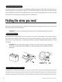
Finding the Wires You Need . .
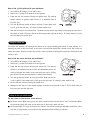
Obtaining Constant 12V . . .
12V Switched Ignition Wire
Starter Wire. . . . . . . . . . .
Door Pin Switch Circuit . . .
.
.
.
.
.
.
.
.
.
.
.
.
.
.
.
.
.
.
.
.
.
.
.
.
.
.
.
.
.
.
.
.
.
.
.
.
.
.
.
.
.
.
.
.
.
8
8
8
9
9
.
.
.
.
.
.
.
.
.
.
.
.
.
.
.
Bypassing Sensor Inputs . . . . . . . . . . . . . . . 25
System Features Learn Routine . . . . . . . . . .
Once a Feature is Programmed . . . . . . . . . .
To Access Another Feature in
the Same Menu . . . . . . . . . . . . . . . .
To Select Another Menu . . . . . . . . . . . . . .
To Exit the Learn Routine . . . . . . . . . . . . .
26
27
27
27
27
System Features Menus. . . . . . . . . . . . . . . . 28
Menu #1-Basic Features . . . . . . . . . . . . . . 28
Menu #2-Advanced Features . . . . . . . . . . . 28
Primary Harness (H1), 12-Pin Connector. . . . 11
Feature Descriptions . . . . . . . . . . . . . . . . . 29
Menu #1-Basic Feature Descriptions . . . . . . 29
Menu #2-Advanced Feature Descriptions . . . 30
Primary Harness (H1) Wire Connection Guide . 11
Transmitter/Receiver Learn Routine . . . . . . . 32
Door Lock Harness (H2), 3-Pin Connector . . . 16
Transmitter Configurations. . . . . . . . . . . . . . 34
Standard Configuration. . . . . . . . . . . . . . . 34
Single Button Arm/Disarm Configuration . . . 34
Making Your Wiring Connections . . . . . . . . . . 10
Door Lock Harness (H2) Wire Connection Guide . 17
Positive-Triggered, Relay Driven
Systems (Type A) . . . . . . . . . . . . . . . . . . 17
Negative-Triggered, Relay Driven
Systems (Type B) . . . . . . . . . . . . . . . . . . 18
Reversing Polarity (Type C) . . . . . . . . . . . . 19
After-market Actuators (Type D). . . . . . . . . 20
Electrically Activated Vacuum (Type E) . . . . 21
One-Wire System, (Type F) . . . . . . . . . . . . 22
Plug-In Harnesses . . . . . .
Super Bright LED . . . .
Valet®/Program Switch.
Programmer Interface .
.
.
.
.
.
.
.
.
.
.
.
.
.
.
.
.
.
.
.
.
.
.
.
.
.
.
.
.
.
.
.
.
.
.
.
.
.
.
.
.
.
.
.
.
.
.
.
.
.
.
.
.
.
.
.
.
22
22
22
23
Multi-Level Security Arming . . . . . . . . . . . . . 35
Table of Zones . . . . . . . . . . . . . . . . . . . . . . 35
Long-Term Event History . . . . . . . . . . . . . . . 36
Optional Vehicle Recovery System . . . . . . . . 36
To Arm VRS . . . . . . . . . . . . . . . . . . . . . . 36
To Disarm VRS . . . . . . . . . . . . . . . . . . . . 37
Rapid Resume Logic . . . . . . . . . . . . . . . . . . 37
Troubleshooting. . . . . . . . . . . . . . . . . . . . . 38
Bitwriter™, Code Hopping™, DEI®, Doubleguard®, ESP™, FailSafe®, Ghost Switch™, Learn
Routine™, Nite-Lite®, Nuisance Prevention Circuitry®, NPC®, Revenger®, Silent Mode™, Soft Chirp®,
Stinger®, Valet®, Vehicle Recovery System®, VRS®, and Warn Away® are all Trademarks or Registered
Trademarks of Directed Electronics, Inc.
2
© 1999 Directed Electronics, Inc. Vista, CA