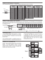
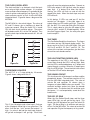
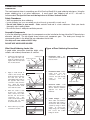
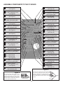
1
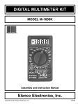
ONE BUTTON BANDIT KIT
MODEL K-34
Assembly and Instruction Manual
Elenco™ Electronics, Inc.
Copyright © 1989 Elenco™ Electronics, Inc.
Revised 2002
REV-D
753234
PARTS LIST
If you are a student, and any parts are missing or damaged, please see instructor or bookstore.
If you purchased this One Button Bandit kit from a distributor, catalog, etc., please contact Elenco™ Electronics
(address/phone/e-mail is at the back of this manual) for additional assistance, if needed.
RESISTORS
Qty.
3
1
1
4
2
1
1
Symbol
R1, R3, R5
R10
R8
R2, R4, R6, R7
R9, R13
R12
R11
Value
220W 5% 1/4W
1kW 5% 1/4W
18kW 5% 1/4W
100kW 5% 1/4W
1MW 5% 1/4W
2.2MW 5% 1/4W
4.7MW 5% 1/4W
Color Code
red-red-brown-gold
brown-black-red-gold
brown-gray-orange-gold
brown-black-yellow-gold
brown-black-green-gold
red-red-green-gold
yellow-violet-green-gold
Part #
132200
141000
151800
161000
171000
172200
174700
CAPACITORS
Qty.
1
4
1
Symbol
C2
C1, C4, C5, C6
C3
Value
.1mF (104)
1mF
4.7mF
Description
Discap
Electrolytic
Electrolytic
Part #
251010
261047
264747
SEMICONDUCTORS
Qty.
9
3
1
12
3
Symbol
D16 - D24
U1, U2, U3
U4
D2-5, D7-10, D12-15
D1, D6, D11
Value
1N4148
4017
MC14584 or CD40106
Description
Diode
Integrated Circuit
Integrated Circuit
LED Red
LED Green
Part #
314148
334017
334584
350002
350010
MISCELLANEOUS
Qty.
1
1
1
1
1
4
3
4
Description
PC Board
Push Button Switch (S2)
Slide Switch (S1)
Battery Holder
Buzzer Piezoelectric (BZ)
Plastic Spacer
Screw 2-56 x 5/16”
Screw 2-56 x 3/4”
Part #
518034
540101
541022
590096
595201
624112
641231
641233
Qty.
7
7
1
3
1
1
1
Description
Nut 2-56 Hex
Flat Washer
14-pin Socket (U4)
16-pin Socket (U1, U2, U3)
Cover Sheet
Wire 22 Black Solid 8”
Solder Tube
PARTS IDENTIFICATION
Resistor
Capacitors
Switches
Integrated Circuit
Diode
Electrolytic
Battery Holder
Slide
Discap
Screws and Nut
2-56
2-56 x 3/4”
2-56 x 5/16”
Shown actual size.
-1-
Push Button
Buzzer
IC
LED
Socket
Spacer
Flat Washer
Part #
644201
645600
664014
664016
750915B
814120
9ST4
IDENTIFYING RESISTOR VALUES
Use the following information as a guide in properly identifying the value of resistors.
BAND 1
1st Digit
Bands
1 2 Multiplier
Tolerance
Color
Black
Brown
Red
Orange
Yellow
Green
Blue
Violet
Gray
White
Digit
0
1
2
3
4
5
6
7
8
9
Multiplier
BAND 2
2nd Digit
Color
Black
Brown
Red
Orange
Yellow
Green
Blue
Violet
Gray
White
Resistance
Tolerance
Color
Multiplier
Black
1
Brown
10
Red
100
Orange
1,000
Yellow
10,000
Green
100,000
Blue
1,000,000
Silver
0.01
Gold
0.1
Digit
0
1
2
3
4
5
6
7
8
9
Color
Silver
Gold
Brown
Red
Orange
Green
Blue
Violet
Tolerance
+10%
+5%
+1%
+2%
+3%
+.5%
+.25%
+.1%
IDENTIFYING CAPACITOR VALUES
Capacitors will be identified by their capacitance value in pF (picofarads), nF (nanofarads), or mF (microfarads).
Most capacitors will have their actual value printed on them. Some capacitors may have their value printed in
the following manner.
For the No.
0
1
2
3
4
5
8
9
Second Digit
Multiplier
Multiplier
First Digit
103K
100
Multiply By
Tolerance
10
100
1k
10k 100k .01
0.1
Note: The letter “R” may be used at times to
signify a decimal point; as in 3R3 = 3.3
10mF 16V
The above value is 10 x 1,000 = 10,000pF or .01mF
1
The letter K indicates a tolerance of +10%
The letter J indicates a tolerance of +5%
INTRODUCTION
The One Button Bandit is better known in Las Vegas
as the One Arm Bandit. Our device has no arms,
but instead a button. Therefore, we call it the One
Button Bandit.
five light emitting diodes (LED). When the switch S2
is pressed, the LEDs will flash on and off
accompanied by sound. When the bandit stops,
only one LED in each column will remain lit. If three
green LEDs light up, you win the jackpot
accompanied by sound.
The One Button Bandit is a simplified version of an
electronic slot machine. It contains three columns of
THEORY OF OPERATION
1
Timer
Figure 1 shows the block diagram of the One Button
Bandit. This block diagram consists of three
identical circuits: (the basic has a timer, a decade
counter, and five LEDs), the Clock Oscillator, the
Sound Circuit and the Key of Ring.
Clock
Counter
LEDs
Timer
Counter
2
LEDs
Sound
Circuit
Figure 1
3
Timer
Counter
-2-
Key
Ring
LEDs
THE CLOCK OSCILLATOR
pulse will move the output one position. Connect an
LED to the output, it will light only when the output
goes high. It is obvious that when the clock is
running, the LEDs will flash on and off with the
speed of the clock. When the clock stops, only one
LED will be lit.
The clock oscillator is an electronic circuit that puts
out a series of high and low voltages. It is a square
wave oscillator whose frequency is controlled by the
value of resistor and capacitor (see Figure 2a). The
clock oscillator consists of Part A of the MC14584
integrated circuit. Figure 2b shows a diagram of the
MC14584.
In this design, 5 LEDs are used per IC, but the
counter has 10 outputs. If the clock stops at an
output without an LED, nothing will light. To prevent
this, the 4017 IC is reset after hitting the 5th output.
This is simply done by tying the 6th output to the
clear pin (pin 1 and pin 15 shorted together). When
the clock triggers output 5 on, the next pulse goes
back to output 1.
The MC14584 is a hex schmit trigger. The values of
R7 and C1 chosen give a frequency of about 30
cycles per second. When the switch S1 is turned
ON, the clock circuit oscillates pulses. The pulses
will be before switch S1 is in the “ON” position. They
go to the clock input of decade counters U1, U2 and
U3 pin 14.
A
1
R
THE TIMER
2
3
B
4
5
C
6
9
D
8
11
E
10
13
F
12
The One Button Bandit has three timers. The timers
start when you turn ON the push button switch. The
timers consist of Part D of the MC14584, R13 and
C6; Part E and R12, C5; Part F and R11, C4. The
values of the resistors and capacitors give the times
of work for each decade counter.
THE LIGHT EMITTING DIODES (LED)
C
THE DECADE COUNTER
The operation of the LED is very simple. When
current flows through the LED, it will emit light. Note
that the LED is connected between an IC output and
ground through a resistor. When the IC output goes
high, the LED will light. The resistor limits the current
so that the LED will not be damaged.
The 4017 IC is a 5 stage divide by 10 counter.
Figure 3 shows a diagram of this IC.
THE SOUND CIRCUIT
Figure 2a
Figure 2b
14
Clock
1
Clock
Enable
15
Reset
Q0
Q1
Q2
Q3
Q4
Q5
Q6
Q7
Q8
Q9
COUT
This circuit consists of the buzzer’s oscillator and the
piezoelectric buzzer. The oscillator consists of Part
B of the MC14584 integrated circuit. The value of
resistor R8 and capacitor C2 chosen given a
frequency of about 3000 cycles per second. This
oscillator oscillates pulses only when the decade
counters work. The pulses from this oscillator go to
the buzzer. It is accompanied by sound when the
bandit works.
3
2
4
7
10
1
5
6
9
11
12
THE KEY OF RING
VCC - Pin 16
GND - Pin 8
When the One Button Bandit stops and the three
green LEDs light, you will get the ring signal. This
sound signal will be before you push the switch S2
again. The Key of Ring is an oscillator and consists
of Part C of the MC14584. The values of resistor R9
and capacitor C3 give the frequency of ring sound.
Figure 3
This IC has 10 outputs and a clear input. Only one
of the 10 outputs will be high at any given time. The
other 9 will be low. Let’s assume that output 1 is
high. If a pulse is fed into the clock input, output 1
will go low and output 2 will go high. Each clock
-3-
CONSTRUCTION
Introduction
The most important factor in assembling your K-34 One Arm Bandit Kit is good soldering techniques. Using the
proper soldering iron is of prime importance. A small pencil type soldering iron of 25 - 40 watts is
recommended. The tip of the iron must be kept clean at all times and well tinned.
Safety Procedures
• Wear eye protection when soldering.
• Locate soldering iron in an area where you do not have to go around it or reach over it.
• Do not hold solder in your mouth. Solder contains lead and is a toxic substance. Wash your hands
thoroughly after handling solder.
• Be sure that there is adequate ventilation present.
Assemble Components
In all of the following assembly steps, the components must be installed on the top side of the PC board unless
otherwise indicated. The top legend shows where each component goes. The leads pass through the
corresponding holes in the board and are soldered on the foil side.
Use only rosin core solder of 63/37 alloy.
DO NOT USE ACID CORE SOLDER!
What Good Soldering Looks Like
Types of Poor Soldering Connections
A good solder connection should be bright, shiny,
smooth, and uniformly flowed over all surfaces.
1.
Solder all components from
the copper foil side only.
Push the soldering iron tip
against both the lead and
the circuit board foil.
1. Insufficient heat - the
solder will not flow onto the
lead as shown.
Soldering Iron
Component Lead
Foil
Soldering iron positioned
incorrectly.
Circuit Board
2.
3.
4.
Apply a small amount of
solder to the iron tip. This
allows the heat to leave the
iron and onto the foil.
Immediately apply solder to
the opposite side of the
connection, away from the
iron.
Allow the heated
component and the circuit
foil to melt the solder.
Allow the solder to flow
around the connection.
Then, remove the solder
and the iron and let the
connection cool.
The
solder should have flowed
smoothly and not lump
around the wire lead.
Rosin
2. Insufficient solder - let the
solder flow over the
connection until it is
covered. Use just enough
solder
to
cover
the
connection.
Soldering Iron
Solder
Foil
Solder
Gap
Component Lead
Solder
3. Excessive solder - could
make connections that you
did not intend to between
adjacent foil areas or
terminals.
Soldering Iron
Solder
Foil
4. Solder bridges - occur
when solder runs between
circuit paths and creates a
short circuit. This is usually
caused by using too much
solder.
To correct this,
simply drag your soldering
iron across the solder
bridge as shown.
Here is what a good solder
connection looks like.
-4-
Soldering Iron
Foil
Drag
ASSEMBLE COMPONENTS TO THE PC BOARD
C5 - 1mF Electrolytic Cap.
(see Figure A)
D22 - 1N4148 Diode
(see Figure D)
U3 - 16-pin IC Socket
U3 - 4017 Integrated Circuit
(see Figure B)
S2 - Push Button Switch
R12 - 2.2MW 5% 1/4W Resistor
(red-red-green-gold)
J4 - Jumper Wire
(see Figure C)
D23 - 1N4148 Diode
(see Figure D)
R11 - 4.7MW 5% 1/4W Resistor
(yellow-violet-green-gold)
R13 - 1MW 5% 1/4W Resistor
(brown-black-green-gold)
C4 - 1mF Electrolytic Cap.
(see Figure A)
D24 - 1N4148 Diode
(see Figure D)
R5 - 220W 5% 1/4W Resistor
(red-red-brown-gold)
C6 - 1mF Electrolytic Cap.
(see Figure A)
J3 - Jumper Wire
(see Figure C)
U4 - 14-pin IC Socket
U4 - MC14584 or CD40106 IC
(see Figure B)
J2 - Jumper Wire
(see Figure C)
R7 - 100kW 5% 1/4W Resistor
(brown-black-yellow-gold)
R6 - 100kW 5% 1/4W Resistor
(brown-black-yellow-gold)
D17 - 1N4148 Diode
(see Figure D)
C1 - 1mF Electrolytic Cap.
(see Figure A)
R10 - 1kW 5% 1/4W Resistor
(brown-black-red-gold)
U2 - 16-pin IC Socket
U2 - 4017 Integrated Circuit
(see Figure B)
D21 - 1N4148 Diode
(see Figure D)
R3 - 220W 5% 1/4W Resistor
(red-red-brown-gold)
R9 - 1MW 5% 1/4W Resistor
(brown-black-green-gold)
R4 - 100kW 5% 1/4W Resistor
(brown-black-yellow-gold)
D20 - 1N4148 Diode
(see Figure D)
D19 - 1N4148 Diode
D18 - 1N4148 Diode
D16 - 1N4148 Diode
(see Figure D)
R8 - 18kW 5% 1/4W Resistor
(brown-gray-orange-gold)
R2 - 100kW 5% 1/4W Resistor
(brown-black-yellow-gold)
C3 - 4.7mF Electrolytic Cap.
(see Figure A)
U1 - 16-pin IC Socket
U1 - 4017 Integrated Circuit
(see Figure B)
S1 - Slide Switch
C2 - .1mF Discap (104)
J1 - Jumper Wire
(see Figure C)
R1 - 220W 5% 1/4W Resistor
(red-red-brown-gold)
Figure B
Insert the IC socket into the PC board with
the notch in the direction shown on the top
legend. Solder the IC socket into place.
Insert the IC into the socket with the notch
in the same direction as the notch on the
socket.
Figure A
Electrolytic capacitors have polarity. Be sure
to mount them with the negative (–) lead
(marked on side) in the correct hole. Mount
the electrolytics horizontal to the PC board.
Bend the leads at right angles and then
insert the leads into the PC board.
Polarity Marking
-5-
Notch
ASSEMBLE COMPONENTS TO THE PC BOARD
D15
D14
D13
D12
D11
Figure C
Form a discarded piece of an
electrolytic lead into a jumper wire by
bending the wire to the correct length
and mount it to the PC board.
-
Red LED
Red LED
Red LED
Red LED
Green LED
(see Figure E)
D10 - Red LED
D9 - Red LED
D8 - Red LED
D7 - Red LED
D6 - Green LED
(see Figure E)
Figure D
Diodes have polarity. Mount them
with the band in the correct direction,
as shown on the PC board.
Band
D5
D4
D3
D2
D1
Figure E
Mount the LED flush
onto the PC board
with the flat side of
the LED in the same
direction as marked
Flat
on the PC board.
-
Red LED
Red LED
Red LED
Red LED
Green LED
(see Figure E)
BZ - Buzzer
Battery Holder
(see Figure F)
Figure F
Mount the battery holder and the buzzer to the
PC board using three 2-56 x 5/16” screws, three
2-56 nuts, and three flat washers (as shown
below). Note: Use a piece of Scotch Tape on
the brass part of the buzzer only to hold it in
place. Cut two 1” pieces of wire and strip 1/4” of
insulation off of both ends. Solder the first wire
from the positive (+) battery holder lead to the
+BATT point on the PC board. Solder the
second wire from the negative (–) battery holder
lead to the –BATT point on the PC board. Cut
off the excess leads. Use an excess lead to
form a jumper wire. Bend the wire as shown
below and solder this jumper from the outer
edge of the buzzer to the –BZ point on the PC
board. Next, cut a 1.5” piece of wire and strip
1/4” of insulation off of both ends.. Solder this
wire from the +BZ point on the PC board to the
middle of the buzzer. Note: Do not let the flat
washers touch the silver part of the buzzer or let
the solder from the wire from the outer edge
touch the silver part.
2-56 Hex Nut
Flat Washer
2-56 Hex Nut
Jumper Wire
0.2”
Flat Washer
Jumper Wire
Tape
Buzzer
Jumper Wire
Buzzer
PC Board
Battery Holder
2-56 x 5/16”
Screw
1” Black Wires
2-56 x 5/16”
Screw
-6-
1.5” Black Wire
Put the 9V alkaline battery into the battery holder.
Slide the switch to the ON (top) position and push
on the button switch. The LEDs will flash ON and
OFF accompanied by sound. If it is OK, go to the
Final Assembly.
TROUBLESHOOTING
Contact Elenco™ Electronics if you have any problems. DO NOT contact your place of purchase as they will
not be able to help you.
1. One of the most frequently occurring problems is
2. Be sure that all components have been mounted
poor solder connections.
in their correct places.
a) Tug slightly on all parts to make sure that
they are indeed soldered.
a) Be sure that diodes D16 - D24 have not
been installed backwards. The band on the
diodes should be in the same direction as
marked on the PC board.
b) All solder connections should be shiny.
Resolder any that are not.
b) Are electrolytics C1, C3 - C6 installed
correctly? These capacitors have polarity.
Be sure that the negative lead is in the
correct pad.
c) Solder should flow into a smooth puddle
rather than a round ball. Resolder any
connection that has formed into a ball.
d) Have any solder bridges formed? A solder
bridge may occur if you accidentally touch
an adjacent foil by using too much solder or
by dragging the soldering iron across
adjacent foils. Break the bridge with your
soldering iron.
c) Be sure that the ICs are installed correctly.
The notch should be in the same direction
as shown on the top legend of the PC board.
d) Be sure that the LED has been installed
correctly. The flat side of the LED should be
in the same direction as marked on the top
legend of the PC board.
FINAL ASSEMBLY
1. Using a small knife or scissors, very carefully cut out the holes on the cover sheet as shown in Figure G.
ONE BUTTON BANDIT
Cut Out
Cut Out
Cut Out
50-1
Cut Out
25-1
15-1
10-1
5-1
ON
5/16” x 5/16”
3/16” x 5/16”
Electronic Slot Machine
PUSH
Wager Back for Any 2 Green Lights
3/32” Diameter
Copyright © 1998 Elenco Electronics, Inc.
Figure G
-7-
Cut Out
2. Next, cut out the holes on the clam shell as
shown in Figure H. To do this, you’re going to
have to position the cover sheet inside the
clamshell to where you want it mounted. Tape
the sheet to the clam shell as shown. Now cut
out the four corner holes, the ON/OFF Switch
hole, and the Push Button Switch hole. Remove
the tape.
ONE BUTTON BANDIT
Tape
50-1
25-1
15-1
10-1
Cut Out
5-1
ON
Cut Out
PUSH
Electronic Slot Machine
Wager Back for Any 2 Green Lights
Tape
Copyright © 1998 Elenco Electronics, Inc.
Cut Out
Figure H
3. Insert the four 2-56 x 3/4” screws and four
washers into the holes of the clamshell and
cover sheet as shown in Figure I. Next, slide on
the four plastic spacers onto the 2-56 x 3/4”
screws as shown in Figure J. Now slide the PC
board onto the screws as shown. Finally, lock
everything into place by threading on the four 2-56
hex nuts onto the screws as shown in Figure J.
Figure I
Flat Washers
2-56 x 3/4” Screws
Flat Washers
2-56 x 3/4” Screws
-8-
FINAL ASSEMBLY (CONTINUED)
2-56 Nuts
PC Board
Figure J
Plastic Spacers
2-56 Nuts
Plastic Spacers
Cover Sheet
QUIZ
1. In electronics, a capacitor is a . . .
a) counter.
c) light emitting diode.
b) generator.d) storage device.
2. LED means . . .
a) light emitting device.
b) light emitting diode.
a) the three green LEDs light.
b) any three LEDs light.
c) three LEDs light up in a row.
6. The buzzer transforms . . .
a) electrical signals to light.
b) electrical signals to sound.
c) light to electrical signals.
c) long electronic delay.
d) light electric diode.
3. The clock oscillator generates a . . .
a) sound pulses.
c) periodic waveform.
b) DC voltage.
d) light pulses.
7. The probability of winning any green LED is . . .
a) 4%
c) 60%
b) 25%
d) 0.8%
4. The decade counter is triggered by . . .
a) the timer.
c) LEDs.
b) the sound circuit.
d) the clock oscillator.
8. The probability of winning three green LEDs is . . .
a) 4%
c) 20%
b) 25%
d) 0.8%
5. The key of ring gives the sound ring signal when . . .
Answers: 1. D; 2. B; 3. C; 4. D; 5. A; 6. B; 7. C; 8. D
-9-
SCHEMATIC DIAGRAM
-10-
Elenco Electronics, Inc.
150 W. Carpenter Avenue
Wheeling, IL 60090
(847) 541-3800
http://www.elenco.com
e-mail: [email protected]