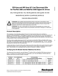
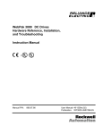
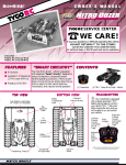
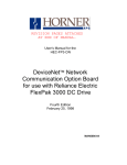
1
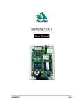
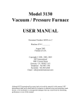
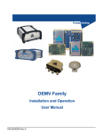
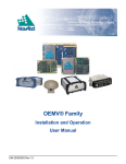
Dynamic Braking Kit for FlexPak 3000 and WebPak 3000 Digital DC Drives 1.5 HP to 30 HP @ 230 VAC, 3 HP to 60 HP @ 460 VAC NEMA 1 Enclosures Model Numbers 908FKxxxx and 909FKxxxx Instruction Manual D2-3313-3 ! ATTENTION: Only qualified personnel familiar with the construction and operation of this equipment and the hazards involved should install, adjust, operate, and/or service this equipment. Read and understand this instruction manual in its entirety before proceeding. Failure to observe this precaution could result in severe bodily injury or loss of life. ATTENTION: The user is responsible for conforming with all applicable local, national, and international codes. Failure to observe this precaution could result in damage to, or destruction of, the equipment. Product Description This instruction manual describes optional Dynamic Braking (DB) kits that can be installed on FlexPak™ 3000 and WebPak™ 3000 Digital DC drives from 1.5 through 60 HP. These kits (908FK and 909FK series models) are designed for use with drives in NEMA 1 enclosures. Hardware Only DB kits (912FK and 913FK series model numbers) used on drives without NEMA 1 enclosures are described in instruction manual D2-3374. Dynamic braking slows down a rotating DC motor and its load. It is an “uncontrolled" process. During dynamic braking, the motor armature is disconnected from the drive. A resistor is placed across the motor's rotating armature (now acting as a generator), and the resulting current causes braking torque in the motor that decays exponentially (assuming there is no overhauling load and a fixed motor field) with the motor's counter-EMF. The motor will decelerate, even with a drive failure, as long as motor field excitation is maintained. The drive must have the DC contactor open for dynamic braking stopping to occur. This typically occurs with a Coast/DB Stop command or a drive fault when the drive is in standby mode. Under drive fault conditions, the DC contactor opens, which applies the dynamic braking grid across the motor for a dynamic braking stop. Reliance, FlexPak and WebPak are trademarks of Rockwell Automation. © 2000 Rockwell International Corporation Verifying the Kit Model Matches the Drive Refer to the following table for the correct kit model number for your drive. Kit Model Number Drive HP 1.5 2 3 5 7.5 10 15 20 25 30 40 50 60 230 VAC 908FK0011 908FK0021 908FK0031 908FK0051 908FK0071 908FK0101 908FK0151 908FK0201 908FK0251 908FK0301 460 VAC 909FK0031 909FK0051 909FK0071 909FK0101 909FK0151 909FK0201 909FK0201 909FK0301 909FK0401 909FK0501 909FK0501 Checking the Contents of the Kit Important: The user must supply power wiring for connection purposes. The contents of NEMA 1 enclosure DB kits are listed in table 2. Description DB Assembly Conduit Plate Control Power Wire Cable Tie 2 Quantity 1 1 1 4 Part Number 802273-70XX 707973-6A 802273-78T 69306-3F Dynamic Braking Kits for FlexPak 3000 and WebPak 3000 Digital DC Drives Installing the Dynamic Braking Kit for 1.5 HP to 30 HP @ 230 VAC and 3 HP to 60 HP @ 460 VAC Drives ! ATTENTION: The drive is at line voltage when connected to incoming AC power. Disconnect, tag and lockout all incoming power to the drive before performing the following procedures. Failure to observe this precaution could result in severe bodily injury or loss of life. ATTENTION: The user is responsible for conforming with all applicable local, national, and international codes. Failure to observe this precaution could result in damage to, or destruction of, the equipment. Step 1. Remove the screened cover from the DB assembly. Important: The removable conduit plate is located on the upper left side of the DB enclosure. An additional conduit plate is supplied for use on the drive when the NEMA 1 cover kit (M/N 904FK0101) is installed. Determine conduit requirements and punch holes in the conduit plates as required. Two conduit holes plugged with plastic caps are located on the top panel of the DB enclosure. Step 2. If the drive has the NEMA 1 cover kit (M/N 904FK0101) installed, locate and drill the mounting holes for the DB enclosure to the right of the drive using the mounting hole pattern located on the back panel. See figure 1. If the drive is mounted in some other NEMA 1 enclosure, the DB kit can be mounted above or next to the drive. Locate and drill the mounting holes for the DB enclosure using the mounting hole pattern located on the back panel. See figure 1. Step 3. Drive the mounting screws (provided by the user) into the mounting panel leaving a minimum of 5 mm (3/16 inch) space between the head of the screw and the mounting panel. Important: Use of 6 mm (1/4 inch) mounting hardware is recommended. Step 4. Slide the slots of the DB assembly panel down over the heads of the mounting screws. Step 5. Tighten the mounting screws firmly to the panel. Step 6. Connect the motor armature leads, A1 and A2, to the power terminal block located on the inside of the DB assembly back panel. See figure 2. Dynamic Braking Kits for FlexPak 3000 and WebPak 3000 Digital DC Drives 3 29.74" [755.3 mm] 24.41" [620.0 mm] 2.76" [70.1 mm] 1.48" [37.5 mm] 6.89" [175.0 mm] 9.84" [250.0 mm] 9.57" [243.0 mm] Front View Side View Figure 1 – DB Kit Enclosure and Mounting Dimensions 4 Dynamic Braking Kits for FlexPak 3000 and WebPak 3000 Digital DC Drives To drive DC power terminal To motor armature To drive DC power terminal <1 A1 A1 A2 S1 S2 45 <1 Remove jumper from A2/S1 when series field is connected. Figure 2 – DB Power Terminal Block Step 7. If the motor has S1 and S2 field leads, remove the S1 and S2 jumper from the power terminal block on the DB assembly back panel. Connect the motor series field leads to their respective terminals. Step 8. Follow the wiring diagram in figure 3 and connect the drive leads, 45 and A1, to terminals 45 and A1 of the DB assembly. Dynamic Braking Kits for FlexPak 3000 and WebPak 3000 Digital DC Drives 5 6 Db Kit Terminals Power Terminal Board Control Terminal Board Drive DB KIT AC INPUT 81 181/L1 1FU A1 281 A1 A1 A1 DB 82 83 182/L2 183/L3 2FU 3FU 282 DB ARMATURE SUPPLY A2 A2/S1 RESISTOR S1 <1 283 230/460VAC 50/60HZ S2 S2 45 16FU 5 182 6 183 182A 17FU (H1) (H3) 183A (X2) (H2) 115 VAC A1 A2 (H4) (X1) DB 13 (33) 1 2 DB AUX 14 (44) 3 2SS R 4 MOTOR SHUNT FIELD 14 13 FN AUX DBCR P6-5 P6-2 F1 4 2 F2 35/F2 3 37/F1 1 2 <2> Remove this jumper on Field/DB terminal board (terminals 3 & 4 ) when connecting DB kit. P5-5 <1> Customer TB for connections to motor with removeable jumper from A2/S1 and S2. This jumper must be removed when series field is connected. P5-6 Dynamic Braking Kits for FlexPak 3000 and WebPak 3000 Digital DC Drives Figure 3 – DB Kit Wiring Diagram 45 FROM FIELD SUPPLY FIELD/DB TB Drive Step 9. Remove the jumper (terminals 3 to 4) from the field/DB terminal block on the drive. See figure 4. Remove Top View Figure 4 – Field/DB Terminal Block Step 10. Connect the drive terminals 1, 2, 3, and 4 to their respective terminals on the DB assembly control terminal block. (The DB assembly control terminal block is located on a bracket above the DB contactor.) See figure 5. Dynamic Braking Kits for FlexPak 3000 and WebPak 3000 Digital DC Drives 7 To drive Field/DB terminal block To drive line fuses (182) (183) Figure 5 – DB Control Terminal Block Step 11. Locate the control transformer at the lower left of the DB assembly back panel. Verify the jumpers on the DB assembly control transformer are connected to the proper terminals (according to line input voltage). See table 3 for jumper settings. Line Voltage 230 VAC 460 VAC Jumper Setting H1-H3 H2-H4 H2-H3 Step 12. Connect the spade connectors (182 and 183) of the control power wire to the male tabs on line terminals 182 and 183 (located at the bottom of the line fuses) on the drive assembly. See figure 6. Step 13. Route the control power wire to the DB assembly control terminal block and connect them to terminals 5 (182) and 6 (183). See figure 5. Step 14. Be sure wires will not come in contact with hot parts or sharp metal edges. Check that all wiring has been correctly connected before energizing the drive. Step 15. Replace the screen cover and secure it with the eight screws you removed in step 1. 8 Dynamic Braking Kits for FlexPak 3000 and WebPak 3000 Digital DC Drives 181 / L1 1FU 182 183 / L2 / L3 2FU 3FU 183 182 Figure 6 – DB Kit to Drive Line Voltage Connection Dynamic Braking Kits for FlexPak 3000 and WebPak 3000 Digital DC Drives 9 Replacement Parts List Description Control Transformer (150 VA) Fuse: 230 VAC Connection (1.5A) 460 VAC Connection (.6A) Contactor: 1.5 to 3 / 3 to 7.5 HP @ 240 / 500 VDC Armature Volts 1. 2. Qty. 1 417155-R Part Number 2 2 64676-64F 64676-64U 1 705310-100A (VAINRUSH = 80, VAHOLD = 10) 5 to 7.5 / 10 to 15 HP @ 240 / 500 VDC Armature Volts 1 705310-110A (VAINRUSH = 100, VAHOLD = 11) 10 to 30/20 to 60 HP @ 240 / 500 VDC Armature Volts 1 705310-141A (VAINRUSH = 490, VAHOLD = 35) Resistor: 20.87 ohms (1.5 HP @ 240 VDC Armature Volts) 11.86 ohms (2 HP @ 240 VDC Armature Volts) 1 2 48267-P 48267-J(1) 9.39 ohms (3 HP @ 240 VDC Armature Volts) 2 48267-H(1) 6.088 ohms (5 HP @ 240 VDC Armature Volts) 2 48267-F(1) 3.824 ohms (7.5 HP @ 240 VDC Armature Volts) 2 48267-D(1) 3.046 ohms (10 HP @ 240 VDC Armature Volts) 2 48267-C(1) 1.932 ohms (15 HP @ 240 VDC Armature Volts) 2 48267-A(1) 1.523 ohms (20 HP @ 240 VDC Armature Volts) 4 48267-C(2) 1.212 ohms (25 HP @ 240 VDC Armature Volts) 4 48267-B(2) 0.966 ohms (30 HP @ 240 VDC Armature Volts) 4 48267-A(2) 49.35 ohms (3 HP @ 500 VDC Armature Volts) 3 48267-N(1) 22.34 ohms (5 HP @ 500 VDC Armature Volts) 3 48267-K(1) 17.79 ohms (7.5 HP @ 500 VDC Armature Volts) 3 48267-J(1) 14.09 ohms (10 HP @ 500 VDC Armature Volts) 3 48267-H(1) 9.132 ohms (15 HP @ 500 VDC Armature Volts) 3 48267-F(1) 6.09 ohms (20 to 25 HP @ 500 VDC Armature Volts) 4 48267-C(1) 4.85 ohms (30 HP @ 500 VDC Armature Volts) 4 48267-B(1) 3.864 ohms (40 HP @ 500 VDC Armature Volts) 4 48267-A(1) 3.00 ohms (50 to 60 HP @ 500 VDC Armature Volts) 3 402422-3D(1) Series Connection Series/parallel connection Reach us now at www.rockwellautomation.com Wherever you need us, Rockwell Automation brings together leading brands in industrial automation including Allen-Bradley controls, Reliance Electric power transmission products, Dodge mechanical power transmission components, and Rockwell Software. Rockwell Automation’s unique, flexible approach to helping customers achieve a competitive advantage is supported by thousands of authorized partners, distributors and system integrators around the world. Americas Headquarters, 1201 South Second Street, Milwaukee, WI 53204, USA, Tel: (1) 414 382-2000, Fax: (1) 414 382 4444 European Headquarters SA/NV, avenue Herrmann Debroux, 46, 1160 Brussels, Belgium, Tel: (32) 2 663 06 00, Fax: (32) 2 663 06 40 Asia Pacific Headquarters, 27/F Citicorp Centre, 18 Whitfield Road, Causeway Bay, Hong Kong, Tel: (852) 2887 4788, Fax: (852) 2508 1846 Reliance Electric Standard Drives Business, 24800 Tungsten Road, Cleveland, OH 44117, USA, Tel: (1) 888 374 8370, Fax: (216) 266 7095 Publication D2-3313-3 - August 2000 2000 Rockwell International Corporation. All rights reserved. Printed in USA. 1999 Rockwell Automation Corporation. All Rights Reserved