1
REVISION PAGES ATTACHED
AT END OF MANUAL.
User’s Manual for the
HEC-FP3-DN
DeviceNet Network
Communication Option Board
for use with Reliance Electric
FlexPak 3000 DC Drive
Fourth Edition
February 25, 1998
MAN0086-04
PREFACE
2-25-98
PAGE 2
PREFACE
This manual explains how to use the Horner’s DeviceNet Network Communication Option Board for use
with the Reliance Electric FlexPak 3000 DC Drive.
Copyright (C) 1998 Horner APG, LLC., 640 North Sherman Drive, Indianapolis, Indiana 46201. All rights
reserved. No part of this publication may be reproduced, transmitted, transcribed, stored in a retrieval
system, or translated into any language or computer language, in any form by any means, electronic,
mechanical, magnetic, optical, chemical, manual or otherwise, without the prior agreement and written
permission of Horner APG, LLC.
All software described in this document or media is also copyrighted material subject to the terms and
conditions of the Horner Software License Agreement.
Information in this document is subject to change without notice and does not represent a commitment on
the part of Horner APG, LLC.
DeviceNet is a trademark of the Open DeviceNet Vendor Association, Inc. (OVDA).
FlexPak 3000 and Reliance are registered trademarks of Reliance Electric Company or its
subsidiaries.
For user manual updates, contact Horner APG, Technical Support
Division, at (317) 916-4274 or visit our website at www.heapg.com.
PAGE 3
2-25-98
PREFACE
LIMITED WARRANTY AND LIMITATION OF LIABILITY
Horner APG, LLC. ("HE") warrants to the original purchaser that the DeviceNet Network Communication
Option Board for use with the Reliance Electric FlexPak 3000 DC Drive manufactured by HE is free from
defects in material and workmanship under normal use and service. The obligation of HE under this
warranty shall be limited to the repair or exchange of any part or parts which may prove defective under
normal use and service within two (2) years from the date of manufacture or eighteen (18) months from
the date of installation by the original purchaser whichever occurs first, such defect to be disclosed to the
satisfaction of HE after examination by HE of the allegedly defective part or parts. THIS WARRANTY IS
E XPRESSLY IN LIEU OF ALL OTHER WARRANTIES EXPRESSED OR IMPLIED INCLUDING THE
WARRANTIES OF MERCHANTABILITY AND FITNESS FOR USE AND OF ALL OTHER OBLIGATIONS
OR LIABILITIES AND HE NEITHER ASSUMES, NOR AUTHORIZES ANY OTHER PERSON TO
ASSUME FOR HE, ANY OTHER LIABILITY IN CONNECTION WITH THE SALE OF THIS DeviceNet
Network Communication Option Board for use with the Reliance Electric FlexPak 3000 DC Drive. THIS
WARRANTY SHALL NOT APPLY TO THIS DeviceNet Network Communication Option Board for use
with the Reliance Electric FlexPak 3000 DC Drive OR ANY PART THEREOF WHICH HAS BEEN
SUBJECT TO ACCIDENT, NEGLIGENCE, ALTERATION, ABUSE, OR MISUSE. HE MAKES NO
WARRANTY WHATSOEVER IN RESPECT TO ACCESSORIES OR PARTS NOT SUPPLIED BY HE.
THE TERM "ORIGINAL PURCHASER", AS USED IN THIS WARRANTY, SHALL BE DEEMED TO
MEAN THAT PERSON FOR WHOM THE DeviceNet Network Communication Option Board for use
with the Reliance Electric FlexPak 3000 DC Drive IS ORIGINALLY INSTALLED. THIS WARRANTY
SHALL APPLY ONLY WITHIN THE BOUNDARIES OF THE CONTINENTAL UNITED STATES.
In no event, whether as a result of breach of contract, warranty, tort (including negligence) or otherwise,
shall HE or its suppliers be liable of any special, consequential, incidental or penal damages including,
but not limited to, loss of profit or revenues, loss of use of the products or any associated equipment,
damage to associated equipment, cost of capital, cost of substitute products, facilities, services or
replacement power, down time costs, or claims of original purchaser's customers for such damages.
To obtain warranty service, return the product to your distributor with a description of the
problem, proof of purchase, post paid, insured and in a suitable package.
ABOUT PROGRAMMING EXAMPLES
Any example programs and program segments in this manual or provided on accompanying diskettes are
included solely for illustrative purposes. Due to the many variables and requirements associated with any
particular installation, Horner APG cannot assume responsibility or liability for actual use based on the
examples and diagrams. It is the sole responsibility of the system designer utilizing the DeviceNet
Network Communication Option Board for use with the Reliance Electric FlexPak 3000 DC Drive to
appropriately design the end system, to appropriately integrate the DeviceNet Network Communication
Option Board for use with the Reliance Electric FlexPak 3000 DC Drive and to make safety provisions for
the end equipment as is usual and customary in industrial applications as defined in any codes or
standards which apply.
Note:
The programming examples shown in this manual are for
illustrative purposes only. Proper machine operation is the sole
responsibility of the system integrator.
PREFACE
2-25-98
PAGE 4
SAFETY NOTICES
DANGER
Only qualified electrical personnel familiar with the construction and operation of this
equipment and the hazards involved should install it. Read and understand this manual
in its entirety before proceeding. Failure to observe this precaution could result in
severe bodily injury or loss of life.
DANGER
The user is responsible for conforming to the nec/cec and all other applicable local
codes. Wiring practices, grounding, disconnects, and overcurrent protection are of
particular importance. Failure to observe this precaution could result in severe
bodily injury or loss of life.
DANGER
Do not install modification boards with power applied to the controller. Disconnect and
lock out incoming power before attempting such installation. Failure to observe this
precaution could result in severe bodily injury or loss of life.
WARNING
Only qualified individuals who are thoroughly familiar with the particular application may
install, operate and maintain this equipment. Before any work is performed, read and
understand this instruction manual as well as the appropriate drive instruction
manual(s). Failure to observe this precaution could result in severe bodily injury.
PAGE 5
2-25-98
PREFACE
TABLE OF CONTENTS
PREFACE ..........................................................................................................................................2
LIMITED WARRANTY AND LIMITATION OF LIABILITY .......................................................................3
ABOUT PROGRAMMING EXAMPLES ................................................................................................3
SAFETY NOTICES .............................................................................................................................4
TABLE OF CONTENTS ......................................................................................................................5
CHAPTER 1: INTRODUCTION...........................................................................................................8
1.1
General.................................................................................................................................8
1.2
Description............................................................................................................................8
1.3
Additional Information ............................................................................................................9
1.4
Related Hardware and Software.............................................................................................9
CHAPTER 2: INSTALLATION ........................................................................................................... 10
2.1
General............................................................................................................................... 10
2.2
Installing the Network Communication Option Board .............................................................. 10
2.2.1
Safety Notices .............................................................................................................. 10
2.2.2
Procedure to Install the Network Communication Option Board ....................................... 10
2.3
Connecting the FlexPak 3000 Controller to a DeviceNet Network ........................................... 13
CHAPTER 3: NETWORK OVERVIEW ............................................................................................... 14
1.2
General............................................................................................................................... 14
3.2
Network Layout ................................................................................................................... 14
3.3
Network Setup..................................................................................................................... 14
3.4
Network Connections ........................................................................................................... 15
3.4.1
Types of Network Connections ...................................................................................... 15
3.4.2
The Polled DeviceNet Connection.................................................................................. 15
3.4.3
The Explicit DeviceNet Connection ................................................................................ 15
3.4.4
The Bit-Strobed DeviceNet Connection .......................................................................... 16
CHAPTER 4: DRIVE CONFIGURATION............................................................................................ 17
1.2
General............................................................................................................................... 17
4.2
Network Communication ...................................................................................................... 17
4.3
Network Connection Types .................................................................................................. 17
4.3.1
Two Types of Network Connections ............................................................................... 17
4.3.2
BASIC Drive Connection ............................................................................................... 17
4.3.3
FULL Drive Connection................................................................................................. 18
4.4
Drive Response to Loss of Network Communication .............................................................. 18
4.4.1
Overview...................................................................................................................... 18
4.4.2
Fault/Alarm Conditions .................................................................................................. 18
CHAPTER 5: PROGRAMMING ......................................................................................................... 20
5.1
Data Types and Transfer Rates ............................................................................................ 20
5.1.1
General ........................................................................................................................ 20
5.2
Data Types and Transfer Rates ............................................................................................ 20
5.2.1
Input Data.................................................................................................................... 20
5.2.2
Output Data.................................................................................................................. 21
5.3
Transfer of Data from the Network Option Board to the Regulator........................................... 21
5.4
Transfer of Data from the Regulator to the Network Option Board........................................... 22
5.5
Tune/Config Update Synchronization Flag ............................................................................ 22
5.6
I/O Update Enable Logic Summary ....................................................................................... 22
5.7
Parameter Processing Error Flag.......................................................................................... 23
5.8
Data Retention Timing Requirements.................................................................................... 23
5.9
Drive Ready Status Bit......................................................................................................... 23
5.10 Network Register Organization............................................................................................. 23
5.11 FlexPak 3000 Parameters Not Accessible Over the Network .................................................. 25
5.12 Poll Connection Data Transfer Format .................................................................................. 26
5.12.1 General ........................................................................................................................ 26
5.12.2 Poll Connection Command Data Format ........................................................................ 26
PREFACE
2-25-98
PAGE 6
5.12.3 Poll Connection Reply Data Format ............................................................................... 27
CHAPTER 6: ELECTRONIC DATA SHEET (EDS) FILE ..................................................................... 28
6.1
General............................................................................................................................... 28
6.2
Installation .......................................................................................................................... 28
6.3
Using the EDS File .............................................................................................................. 30
6.4
Data Mapping...................................................................................................................... 32
APPENDIX A - FLEXPAK 3000 PARAMETERS ................................................................................. 33
APPENDIX B: POLL CONNECTION DATA FORMAT........................................................................ 53
APPENDIX C: EXPLICIT MESSAGING FOR THE HEC-FP3-DN ........................................................ 55
1.1
General............................................................................................................................... 55
1.2
Explicit Message Format ...................................................................................................... 55
1.3
Explicit Message Response Format ...................................................................................... 56
1.4
Explicit Message Error Format.............................................................................................. 56
1.4.1.1 Components of an Explicit Error Message (See Table C.4).............................................. 57
1.5
Error Codes ........................................................................................................................ 58
1.6
Using Explicit Messages and Polling with the Same Device.................................................... 59
PAGE 7
2-25-98
This Page Intentionally Left Blank
PREFACE
CHAPTER 1: INTRODUCTION
2-25-98
PAGE 8
CHAPTER 1: INTRODUCTION
1.1
General
1.1.1 The Horner DeviceNet Network Communication Option Board is designed to allow a
Reliance FlexPak 3000 (version 3.1 or higher) to be operated and monitored via the DeviceNet
network. The option board makes use of the parallel-bus connection port on the FlexPak 3000
controller. The option board mounts behind the regulator board inside the FlexPak 3000 carrier
assembly and connects to the regulator board via a flexible ribbon cable. Power for the option
board comes from the FlexPak 3000 controller power supply.
1.1.2 In normal operation, the drive can be completely controlled via the network option board.
In many applications, there may be only a network interface connection, a hard-wired emergency
stop (function loss input), and three-phase input and output power wiring. Start, stop, fault codes
and complete control can be accomplished over the DeviceNet network.
1.2
Description
1.2.1 The section describes the mechanical and electrical characteristics of the DeviceNet
Network Communication Option Board.
a.
Mechanical Description
The DeviceNet Network Communication Option Board is a printed circuit assembly that mounts
inside a FlexPak 3000 Controller. It connects to the regulator board within the controller via a
ribbon cable. It has a standard DeviceNet 5-pin "pluggable" screw-terminal connector which is
used to connect a DeviceNet cable (dual twisted pairs with shield).
b.
Electrical Description
The DeviceNet Network Communication Option Board contains its own microprocessor. The
microprocessor connects to one port of the board's dual port memory while the other port
interfaces to the FlexPak 3000 regulator. The board contains a watchdog timer which is enabled
when power is turned on the controller. The microprocessor must reset the watchdog timer within
a specified period or the microprocessor will shut down resulting in a fault.
At power-up, the microprocessor will run diagnostics on the CPU, EPROM, RAM, memory
management unit, and dual-port memory. If there is an error during diagnostics, a fault will be
generated, and the output parameter NETWORK KIT (P.796) (available in the OIM's Drive
Information menu) will indicate "FAILED DIAGS". If the power-up self-tests pass, the NETWORK
KIT parameter will indicate "INSTALLED".
Each option card requires a maximum of 95mA @ 11VDC of DeviceNet network power for the
transceiver circuit to operate.
PAGE 9
1.3
2-25-98
CHAPTER 1: INTRODUCTION
Additional Information
1.1.3 The user must be familiar with all of the instruction manuals that describe the system
configuration. This may include, but is not limited to, the following:
D2-3335
1.4
FlexPak 3000 Digital DC Drives
(1½-75HP @ 230VAC, 3-300HP @ 460 VAC)
Related Hardware and Software
1.4.1 The option board package consists of one DeviceNet network communication option
board, which provides a single connection to a DeviceNet network. This board can be mounted
inside a FlexPak 3000 controller, which can then be used with the following hardware and
software (purchased separately from Allen-Bradley):
a.
b.
c.
d.
e.
f.
1747-SDN
1746-P2
1747-L532
1746-A4
1787-MGR
1747-PA2E
SLC500 DeviceNet Scanner Module
SLC500 Power Supply
SLC503 Central Processing Unit
SLC500 Rack
DeviceNet Manager Software
SLC500 Advanced Programming Software
Note: The list includes the devices that would be required to construct an SLC500-based
DeviceNet controller. This is only one example of the many different DeviceNet controller
combinations that can be used.
CHAPTER 2: INSTALLATION
CHAPTER 2:
2.1
2-25-98
PAGE 10
INSTALLATION
General
2.1.1 The section describes how to install the DeviceNet Network Communication Option
Board into the FlexPak 3000 controller and how to connect the controller to a DeviceNet network.
2.2
Installing the Network Communication Option Board
2.2.1
Safety Notices
a.
Danger
Only qualified electrical personnel familiar with the construction and operation of this equipment
and the hazards involved should install it. Read and understand this manual in its entirety before
proceeding. Failure to observe this precaution could result in severe bodily injury or loss
of life.
b.
Danger
The user is responsible for conforming to the nec/cec and all other applicable local codes. Wiring
practices, grounding, disconnects, and overcurrent protection are of particular importance.
Failure to observe this precaution could result in severe bodily injury or loss of life.
c.
Danger
Do not install modification boards with power applied to the controller. Disconnect and lock out
incoming power before attempting such installation. Failure to observe this precaution could
result in severe bodily injury or loss of life.
d.
Warning
Only qualified individuals who are thoroughly familiar with the particular application may install,
operate and maintain this equipment. Before any work is performed, read and understand this
instruction manual as well as the appropriate drive instruction manual(s). Failure to observe
this precaution could result in severe bodily injury.
2.2.2
Procedure to Install the Network Communication Option Board
2.2.2.1 Use the following procedure to install the Network Communication Option Board. Refer
to Figures 2.1, 2.2, and 2.3 for mounting locations.
1.
Turn off, lock out, and tag all incoming power to the FlexPak 3000 drive.
2.
Loosen and remove the two (2) mounting screws on the FlexPak 3000 drive cover and
remove the cover.
3.
Loosen the captive screw on the carrier and swing open the carrier.
4.
Loosen and remove the four screws attaching the carrier shield to the carrier.
5.
Remove the connector attaching the shield's ground wire to the drive's power supply. Set
the shield aside.
6.
Position the Option board over the molded standoffs.
PAGE 11
2-25-98
CHAPTER 2: INSTALLATION
7.
Secure the Option board using three (3) captive screws on the board.
8.
Plug the Option board ribbon cable into the Option board.
9.
Re-attach the carrier shield's ground wire to the drive's power supply.
10.
Re-attach the carrier shield to the carrier.
11.
Close the carrier and fasten it with the captive screw.
12.
Route the DeviceNet network cable through the leftmost opening at the bottom of the
controller. With the contacts numbered 1-5 from left to right, connect as described below:
Pin 1:
Pin 2:
Pin 3:
Pin 4:
Pin 5:
VCAN_L
SHIELD
CAN_H
V+
(black)
(blue)
(bare)
(white)
(red)
13. Re-install the FlexPak 3000 drive cover.
NS MS
P1 P2 P3 P4 P5
Figure 2.1 - DeviceNet Option Board End View
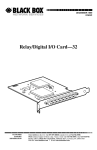
Figure 2.2 - Carrier Shield Removal
CHAPTER 2: INSTALLATION
2-25-98
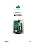
Figure 2.3 - Installing the Network Communications Option Board
PAGE 12
PAGE 13
2.3
2-25-98
CHAPTER 2: INSTALLATION
Connecting the FlexPak 3000 Controller to a DeviceNet Network
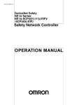
2.3.1 When connecting to the DeviceNet network, the FlexPak 3000 controller should be wired
with the same cabling and termination as any other DeviceNet device. For additional information,
refer to Volume 1 of the DeviceNet Specification, Chapter 9.
Figure 2.4
CHAPTER 3: NETWORK OVERVIEW
CHAPTER 3:
1.2
2-25-98
PAGE 14
NETWORK OVERVIEW
General
3.1.1 The DeviceNet Network Communication Option Board provides the Reliance FlexPak
3000 DC Drive with connectivity to a popular industrial network, DeviceNet. Through this option
board, the FlexPak 3000 can reside on an industrial control network with a host of industrial
control products. The FlexPak 3000 can, then, be easily monitored and/or controlled by a PLC
through a DeviceNet Scanner module residing in a PLC. This allows a great deal of flexibility in
the way that the FlexPak 3000 is controlled, and also, the amount and type of data that can be
passed to and from the drive. This capability adds flexibility to the way FlexPak 3000 DC Drives
can be integrated in an industrial control application.
3.2
Network Layout
3.2.1 The DeviceNet standard supports up to 64 nodes on a single network. Because
DeviceNet is a master-slave network, it requires that a DeviceNet Master or Scanner be present
on the network. The Scanner establishes all connections and initiates all communications with
network devices.
3.2.2 In a typical industrial application, a DeviceNet network consists of a scanner and one or
more DeviceNet devices which operate by manipulating PLC memory.
3.3
Network Setup
3.3.1 DeviceNet is a network consisting of four wires plus shield. Five connections are typically
made to each device on the network including two for power, two for communications signals,
and one for shield.
3.3.2
Each device on the network must be configured using:
a.
b.
Data rate and node address, and
Device-specific information.
3.3.3
There are three methods to configure the devices:
a.
b.
c.
Mechanical switches only,
Parameter values stored in the device's memory, and
Electronic data sheet files.
The option card is configured using parameter values stored in its memory. These parameter
values are set from the FlexPak 3000 keypad. See Chapter 4 for details.
PAGE 15
3.4
Network Connections
3.4.1
Types of Network Connections
2-25-98
CHAPTER 3: NETWORK OVERVIEW
3.4.1.1 When a FlexPak 3000 DC Drive (using the DeviceNet Network Communications Opton
Board) is configured and resides on an active DeviceNet network, a significant amount of FlexPak
3000 data is accessible over the network. The data may be read and/or written from the drive by
the DeviceNet master or scanner.
3.4.1.2 The DeviceNet data may be accessed by the master through three distinct "connections",
these are:
a.
b.
c.
Polled connection,
Explicit connection
Bit-strobed connection.
3.4.2
The Polled DeviceNet Connection
3.4.2.1 The Polled DeviceNet connection provides the primary means of drive control and
monitoring. The DeviceNet master establishes the polled connection and transfers OUTPUT data
in poll command messages. The drive returns INPUT data in poll reply messages. Note that all
of the data accessible through the poll connection is also accessible through the explicit
connection.
3.4.2.2 Some applicationsl make use of a large number of drives with limited functionality
connected to a single network. Only certain parameters and diagnostic information commonly
used are required for network control. Complete configuration over the network is not a
requirement for low-cost, high performance network applications. This type of poll connection is
referred to as the control only poll connection. The network master issues a poll command that
contains 4 words of data for output to the drive, and the drive returns a series of poll reply
messages that contain 8 words of input data from the drive.
3.4.2.3 Other applications accept a slower network in exchange for greater drive parameter
access over the network. This type of poll connection is referred to as the control + config poll
connection. When the drive is configured in this manner, the network master issues a series of
poll commands that contains 26 words of data, and the drive returns a series of poll reply
messages that contains 13 words of data. Since a greater amount of network data is transferred,
the network scan rate performance is adversely affected
3.4.2.4 The amount of data transferred through the polled connection is dependent on the drive
configuration performed in Section 4.2. Poll command/reply data format is defined in Section
5.12.
3.4.3
The Explicit DeviceNet Connection
3.4.3.1 The Explicit DeviceNet connection is required of all DeviceNet modules. Through this
connection, the DeviceNet master can:
a.
Establish communication through all 3 connections.
b .
Access DeviceNet object information
c.
Access ALL FlexPak 3000 network parameters. (See Section 5.10 for a list of drive
parameters and the method used to access them through the explicit connection).
CHAPTER 3: NETWORK OVERVIEW
2-25-98
PAGE 16
3.4.3.1 The explicit connection is primarily used by the DeviceNet controller to initially establish
communications. Once the poll and/or strobe connections are established, the controller will
normally access the drive data through them.
3.4.4
The Bit-Strobed DeviceNet Connection
3.4.4.1 The bit-strobed connection allows a DeviceNet master to send one bit of information
simultaneously to all devices on the network. The bit of information is used for different purposes
by different devices residing on the network.
3.4.4.2 The FlexPak 3000 (with communications option board) uses the bit received in a bitstrobe connection as a start command.
It allows the multiple drives to be started
"simultaneously", although it may take up to 100mS. for all drives to start.
PAGE 17
CHAPTER 4:
1.2
2-25-98
CHAPTER 4: DRIVE CONFIG.
DRIVE CONFIGURATION
General
The section describes how to configure the FlexPak 3000 controller containing the DeviceNet
Network Communication Option Board for use on the DeviceNet network. Refer to the FlexPak
3000 Installation and Operation instruction manual for more information on the drive parameters
described below.
4.2
Network Communication
4.2.1 The drive becomes active on the DeviceNet network after the user performs the following
steps. Note that these steps should be followed in the order listed to prevent drive fault(s). (The
HEC-FP3-DN Card cannot be used in conjunction with Automax card).
1.
Connect the Network Option board to the network via the standard "pluggable" DeviceNet
connector (See Section 2.2 for wiring information).
2.
Apply power to the drive.
3.
Using the keypad, access the drop number assignment parameter (NETW DROP
NUMBER (P.900)) and assign a valid DeviceNet network drop number to the drive.
4.
Using the keypad, access the network connection type parameter (NETW CONNECT
TYPE (P.910)) and select either Basic Drive Connection or Full Drive Connection.
5.
Using the keypad, access the DeviceNet Baud Rate (NETW BUAD RATE) (P.912)
parameter and select 125.0 KBAUD, 250.0 KBAUD, 500.0KBAUD, or OTHER.
6.
Using the keypad, access the DeviceNet poll message type (DEVNET POLL MSG TYPE)
(P.913) and select CONTROL ONLY or CONTROL+CONFIG.
7.
Apply power to the DeviceNet network.
4.3
Network Connection Types
4.3.1
Two Types of Network Connections
4.3.1.1 The drive's network connection type defines the scope of data and control that the master
has with the connected drive. Two types of connections are provided: BASIC drive connection
and FULL drive connection. The drive's network connection type is selected with a drive
parameter (NETW CONNECT TYPE (P.910)).
4.3.2
BASIC Drive Connection
4.3.2.1 Select BASIC drive connection if the application does not require a complete
configuration of the drive over the network. Only certain parameters and diagnostic information
commonly used will be controlled over the network. Selecting this option for NETW CONNECT
TYPE (P.910) results in data size of 64 words.
CHAPTER 4: DRIVE CONFIG.
4.3.3
2-25-98
PAGE 18
FULL Drive Connection
4.3.3.1 Select FULL drive connection if your application requires the ability to configure the drive
over the network and to have access to almost all parameters, operating variables, and
diagnostic information.. Selecting this option for NETW CONNECT TYPE (P.910) results in a data
size of 256 words.
4.4
Drive Response to Loss of Network Communication
4.4.1
Overview
4.4.1.1 The Network Option board will attempt to remain active on the network at all times.
Whenever communication is interrupted, the board will immediately notify the drive regulator of
this occurrence and then attempt to re-establish communication with the network master. To
eliminate extraneous fault conditions at power-up, the drive will delay for approximately 10
seconds after power-up before indicating a fault/alarm condition. A fault/alarm condition will be
indicated if network communication is not established before the 10 second power-up timer
expires, or if network communications was established and then lost.
4.4.2
Fault/Alarm Conditions
a.
If CONTROL SOURCE SELECT ((P.000) on the DCM) is not set to NETWORK (3), the
loss of network communication will not cause a fault or alarm to occur. If CONTROL SOURCE
SELECT is set to NETWORK, the drive will react to the network communication loss based on
how the communication loss selection parameter (NETW COMM LOSS SELECT (P.901)) has
been configured.
b.
If NETW COMM LOSS SELECT (P.901) is set to FAULT (0), the drive will consider a
loss of network communication a drive fault resulting in a coast/DB stop. In this case, the
response to network communication loss is as follows:
1. The drive will latch a fault condition and perform a coast/DB stop.
2. A fault will be logged in the drive's fault log and will be displayed on the front-panel display
(“NETWORK COMMUNICATION LOSS").
3. The text that appears over the front panel CONTROL SOURCE SELECT key (“NETWORK")
will blink indicating that the network is inactive.
4. Once network communications has been re-established, a drive fault reset will be required
before the drive can be re-started. (Note: A fault reset does not clear the fault log).
PAGE 19
2-25-98
CHAPTER 4: DRIVE CONFIG.
c.
If NETW COMM LOSS SELECT is set to HOLD LAST REF (1), the drive will continue
to operate using the last reference received from the network master. In this case, the response
to network communication loss is as follows:
1. An alarm will be logged in the alarm log.
2. An entry will be made into the drive's error log for each active-to-inactive transition of network
communication status.
3. The front-panel display will indicate that a “NETWORK COMMUNICATION LOSS" alarm has
occurred.
4. The text that appears over the front panel CONTROL SOURCE SELECT key (“NETWORK")
will blink indicating that the network is inactive.
5. The drive can be stopped using the hardwired stop input (coast/DB stop, CTB-8) or by
pressing the front panel stop key (STOP MODE SELECT). Once stopped, the drive cannot be restarted until network communication is re-established or CONTROL SOURCE SELECT is
changed.
6. If the drive is still running when network communications has been re-established, the drive
will once again follow the reference and sequencing control inputs supplied by the network
master.
WARNING
The controller is not equipped with a coast-stop push-button. The user must install a hardwired
operator-accessible push-button that provides a positive interrupt and shuts down the drive.
Failure to observe this precaution could result in bodily injury.
NOTE: When NETW COMM LOSS SELECT is set to HOLD LAST REF, it may not always be
possible to stop the drive over the network after a comm loss has occurred. A hardwired stop
must be used to stop the drive.
d.
If NETW COMM LOSS SELECT (P.901) is set to USE TRMBLK REF (2), the drive will
continue to operate using the selected auto reference value obtained from the terminal block
inputs. In this case, the response to network communication loss is as follows:
1. An alarm will be logged in the alarm log.
2. The front-panel display will indicate that a “NETWORK COMMUNICATION LOSS" alarm has
occurred.
3. The text that appears over the front panel CONTROL SOURCE SELECT key (“NETWORK")
will blink indicating that the network is inactive.
4. The drive can be stopped using the hardwired stop input (coast/DB stop, CTB-8), by pressing
the front panel stop key (STOP MODE SELECT), or by using the terminal block stop input (STOP
MODE SELECT, CTB-3). Once stopped, the drive cannot be re-started until network
communication is re-established or CONTROL SOURCE SELECT is changed.
5. If the drive is still running when network communication has been re-established, the drive will
once again follow the reference and sequencing control inputs supplied by the network master.
The terminal block stop input (CTB -3) will no longer be active.
WARNING
The controller is not equipped with a coast-stop push-button. The user must install a hardwired
operator-accessible push-button that provides a positive interrupt and shuts down the drive.
Failure to observe this precaution could result in bodily injury.
NOTE: When NETW COMM LOSS SELECT is set to USE TRMBLK REF, it may not always be
possible to stop the drive over the network after a comm loss has occurred. A hardwired stop
must be used to stop the drive.
CHAPTER 5: PROGRAMMING
CHAPTER 5:
2-25-98
PAGE 20
PROGRAMMING
5.1
Data Types and Transfer Rates
5.1.1
General
5.1.1.1 In order to minimize regulator board CPU loading, the transfer of register data between
the HEC-FP3-DN and the drive regulator board will not occur at all times and will not occur at the
same rate.
5.1.1.2 The sections that follow describe the data types for input and output register data, along
with typical drive information in each category. The specific register list for the FlexPak 3000
controller appears in Section 5.3.
5.2
Data Types and Transfer Rates
5.2.1
Input Data
5.2.1.1 The drive input data is categorized as one of three types: Control/reference, tunable, or
configurable.
a.
Control/reference inputs include data which require fast update rates. This includes
data such as sequencing inputs (start, stop, run/jog, fwd/rev, etc.) and speed/torque reference.
Control/reference inputs are transferred from the network option board to the regulator board
every speed loop scan period (for the FlexPak 3000, every 20 milliseconds), or as often as it is
required by the drive. For example, if the drive is configured to obtain its torque reference from
the option port, it will read this data from the option port every current minor loop scan.
b.
Tunable inputs include parameters which typically require modification or adjustment
while the drive is running. Tunable data includes parameters such as accel/decel rates, min/max
limits, gains or offsets, etc.
Tunable inputs are transferred from the network option board to the regulator board whenever the
regulator performs the processing of new tunable parameters. This occurs approximately every
100 milliseconds while the drive is running or stopped.
c.
Configurable inputs include parameters which alter the way that the drive operates in
such a way that they cannot be modified while the drive is running. Configuration data includes
parameters such as reference source selection, I/O configuration, motor/tach nameplate data,
etc.
Configurable inputs are transferred from the network option board to the regulator board
whenever the regulator performs processing of new configuration parameters. This occurs
approximately every 100 milliseconds while the drive is stopped. Values sent from the network
master while the drive is running will not be read in and used by the drive regulator until the drive
is stopped.
PAGE 21
5.2.2
2-25-98
CHAPTER 5: PROGRAMMING
Output Data
5.2.2.1 The drive output data is categorized as one of two types:
tunable, configuration and status data.
Runtime signal data, or
a.
Runtime signal data includes items such as selected speed reference value,
sequencing status (ready, running, etc.), drive fault flags, terminal block digital inputs state, and
front-panel display mode values (RPM, Volts, Amps). The information is transferred from the
regulator board to the network option board every speed loop scan period (for the FlexPak 3000,
every 20 milliseconds).
b.
Tunable, configuration and status data includes all other information provided by the
drive which is not defined as runtime signal data. This would typically include all drive parameter
values. When accessed via the DeviceNet explicit connection, this data provides a complete
image of how the drive is configured and operating. Tunable, configuration and status data are
transferred from the regulator board to the network option board whenever the regulator performs
the processing of new tunable and configurable input parameters. This occurs every 100
milliseconds.
5.3
Transfer of Data from the Network Option Board to the Regulator
5.3.1 The network option must be actively communicating with the master and it must be
selected as the drive control source (P.000 = Network (3) on DCM or Control Source Select
Screen Set to “Network” on OIM) in order for any inputs to be transferred from the network option
board to the drive regulator.
5.3.2 Note that the keypad can still be used to change parameter values when the drive control
source is the network option. However, any changes made via the keypad will be overwritten
when the next network update occurs (if the network option is configured to update the specified
keypad parameter). This should be kept in mind if parameter changes need to be made while the
network option is the control source for the drive.
5.3.3 In addition, a network -master-controlled tune/config input enable bit (word 32, bit 14) is
provided to enable the transfer of tunable and configurable inputs from the network option board
to the drive regulator. Until this bit is set ON (1), only control/reference data are read in by
the drive. This gives the master's application program direct control over when tunable and
configurable parameter values are read in by the drive, if at all.
5.3.4 For example, the master application program would typically initialize the tunable and
configurable parameter data in the master's network card dual-port memory before turning on the
tune/config input enable bit.
5.3.5 Another example would be an application which only wants to send control/reference
data to the drive. In this case, the master would always leave the tune/config input enable bit
OFF. The drive would then be configured locally, but start, stop, reset and reference would be
sent from the network master.
5.3.6 Note that when the drive's poll connection is configured for control only operation, the
tune/config input enable bit is forced to 0, regardless of its state in the poll command data.
CHAPTER 5: PROGRAMMING
5.4
2-25-98
PAGE 22
Transfer of Data from the Regulator to the Network Option Board
5.4.1 All output data provided is transferred to the network option board at all times. The
network does not have to be active and the network option does not have to be selected as the
drive control source (P.000). No output enable control bit is necessary.
5.5
Tune/Config Update Synchronization Flag
5.5.1 To allow the network master's application program to determine when tunable and
configurable inputs have been updated in the drive, a master write bit (Register 32, bit 15) is
provided which is copied to a master write bit (Register 0, bit 7) by the drive. The drive will copy
the master write bit to the master read bit after the drive has read in and processed all tunable
and/or configurable input registers. The tune/config input enable bit must be set (1) in order for
this to happen. Note that configurable type inputs are only read in by the drive while it is not
running. This will not affect the copying of the network synchronization bit since tunable inputs
will still be transferred.
5.5.2 By toggling the network synchronization bit in the master and by monitoring the copied
value from the drive, the master's application program can determine when the drive has read in
that data. This feature is provided for those applications which may require this type of
synchronization. It is not necessary for the master's application program to use it, as it has no
affect on drive operation. To determine when changes to tunable and configurable data on the
drive have been completed, the master would perform the following sequence:
Step 1. Modify the tunable and/or configurable register data in the appropriate network
register(s).
Step 2. Set the tune/config input enable flag (if not already set).
Step 3. Toggle the network synchronization flag.
Step 4. Monitor the loopbacked copy (read register) of the network synchronization flag until
it equals the value written in step 3.
5.6
I/O Update Enable Logic Summary
5.6.1
The following logic strings summarize the output and input enable logic described above.
Figure 5.1- Logic Strings
PAGE 23
2-25-98
CHAPTER 5: PROGRAMMING
5.6.2 OUTPUTS UPDATED indicates when all output data is transferred from the drive
regulator to the network option board memory and consequently to the master.
5.6.3 CNTL/REF INPUTS UPDATED, TUNE INPUTS UPDATED, and CONFIG INPUTS
UPDATED indicate when control/ref, tunable, and configurable inputs, respectively, are
transferred from the network option board memory to the drive regulator.
5.7
Parameter Processing Error Flag
5.7.1 A parameter processing error status flag (Register 0, bit 12) is provided to allow the
network master to determine whether any parameter values are unacceptable to the drive. If this
flag is set (1), then one or more parameters sent to the drive were rejected. If this flag is not set
(0), then all parameters sent to the drive were accepted.
5.7.2 Note that the tune/config inputs enable bit must be set (1) before the drive can read in,
and consequently process, any tune/config parameters. The parameter processing error flag is
updated approximately every 100 milliseconds.
5.8
Data Retention Timing Requirements
5.8.1
All tunable and configuration drive input register values must be maintained by the
network master's application program for at least 500 msec. to assure that they are seen by the
drive. The 500 msec. is in addition to the time required by the network master to transmit this data
to all the FlexPak 3000 drops (dependent on the number of devices on the network). This is
particularly relevant for data which is detected by the drive only on transition.
5.8.2
Control/Reference data types do not have this 500 msec. requirement. They are
scanned (read in) by the drive every 20 msec. The Run and Jog inputs and the Fault and Alarm
Log Clear command input are exceptions, and are described below.
5.8.3 The Run and Jog inputs requires a 0-to-1 transition in order to start the drive. Processing
the Run and Jog inputs from the network may be delayed by the drive for up to 100 msec. This is
done to synchronize a drive start to the processing of new configuration data. In order for the
network master to assure this 0-to-1 transition is detected by the drive, the network master must
maintain both the 0 and 1 states for at least 100 msec. Values which are maintained for less time
may not be detected by the drive.
5.9
Drive Ready Status Bit
5.9.1 The Drive Ready status bit (Drop 1, reg. 0 bit 0) is used to indicate that a 0-to-1 transition
on the Run or Jog input will start the drive. The Drive Ready bit will be ON (1) when all of the
following conditions are met, and OFF (0) when one or more are not met:
a.
b.
c.
d.
e.
No drive faults are active (Drop 1, reg. 0 bit 2 = 0)
Stop input is ON (Drop 1 reg. 32 bit 1 = 1)
Front -panel STOP/RESET button is not pressed
Coast/DB Stop terminal block input is closed (Drop 1, reg. 0 bit 10 = 1)
Customer Interlock terminal block input is closed (Drop 1, reg. 0, bit 11 = 1)
5.10
Network Register Organization
5.10.1
When the drive network connection type parameter (NETW CONNECT TYPE (P.910))
is configured for BASIC drive connection, the FlexPak 3000 drive will communicate its first 64
CHAPTER 5: PROGRAMMING
2-25-98
PAGE 24
registers to the network communications card. Through an “Explicit” DeviceNet connection, all of
this data is available to the DeviceNet master.
5.10.2 When the drive Network Connection Type is configured for FULL drive connection, the
FlexPak 3000 drive will communicate all 256 of its registers to the network communications card.
Through an All of this data is available to the DeviceNet master through an “Explicit” DeviceNet
connection.
Register #s
0-63
64-127
128-191
192-256
Automax References
0-63, Drop 1 (Table A.1)
0-63, Drop 2 (Table A.2)
0-63, Drop 3 (Table A.3)
0-63, Drop 4 (Table A.4)
The complete list of FlexPak 3000 parameters are located in Tables A.1 - A.4 in Appendix A.
PAGE 25
5.11
2-25-98
CHAPTER 5: PROGRAMMING
FlexPak 3000 Parameters Not Accessible Over the Network
5.11.1 The following FlexPak 3000 parameters are not accessible over the network at any time.
Table 5.1 – FlexPak 300 Parameters
FlexPak 3000 Parameter Name
Parameter #
FlexPak 3000 Parameter Name
Parameter #
CT TURNS RATIO
P.010
CML ERROR
P.398
MANUAL REF SELECT
P.106
ARMATURE DELTA
P.399
MOP ACCEL TIME
P.115
METER OUT 1 GAIN ADJ
P.400
MOP RESET ENABLE
P.116
METER OUT 2 GAIN ADJ
P.401
PRESET SPEED 1
P.117
METER OUT 1 ZERO ADJ
P.402
PRESET SPEED 2
P.118
METER OUT 2 ZERO ADJ
P.403
PRESET SPEED 3
P.119
METER OUT 1 SELECT
P.404
MOP DECEL TIME
P.120
METER OUT 2 SELECT
P.405
TORQUE REFERENCE
P.189
FLD CURRENT REGULATOR
P.586
MOP OUTPUT
P.191
FIELD DELTA HIGH LIM
P.587
ANALOG MAN REFERENCE
P.192
FIELD DELTA
P.588
DRAW PERCENTAGE OUT
P.196
J20 FIELD LOSS DETECT
P.597
SPEED RAMP INPUT TP
P.198
J21 FLD SUPPLY JUMPER
P.598
SPEED RAMP OUTPUT
P.199
J11 ANLG TACH VLT SCL
P.792
SELF TUNE FIELD RANGE
P.218
J14 ANLG TACH VLT RNG
P.793
SELF TUNE STABILITY
P.219
POWER UNIT TYPE
P.795
SELF TUNE BRIDGE
P.220
NETWORK KIT
P.796
IR COMPENSATION TP
P.290
I/O EXPANSION KIT
P.797
CURRENT COMPOUND TP
P.293
PULSE TACHOMETER KIT
P.798
JOG RAMP OUTPUT
P.294
J15 REGULATOR TYPE
P.799
SPD LOOP LAG OUTPUT
P.298
OCL REFERENCE
P.845
PHASE FIRE TEST DELTA
P.309
OCL FEEDBACK
P.847
PHASE FIRE TST BRIDGE
P.310
OCL ENABLE
P.849
A-C LINE PERIOD
P.393
NETW DROP NUMBER
P.900
J18 ARM I FB RESISTOR
P.395
CML FEEDBACK
P.397
CHAPTER 5: PROGRAMMING
5.12
2-25-98
PAGE 26
Poll Connection Data Transfer Format
5.12.1 General
As described in Section 4.3.3, the DeviceNet polled connection is used in most cases to
accomplish drive control. The following information illustrates the data format that is expected
and returned by the drive when using the polled connection:
5.12.2 Poll Connection Command Data Format
Word#
0
1
2
3
Description
Drive Control
Speed Control
Network Input Reg #1
Field Reference Reg
(Poll connection consumption size = 8 bytes)
The following data should only be sent in the poll command message if the drive is configured to
accept control + config data in the poll command message. (See Section 4.2.)
4
5
6
7
8
9
10
11
12
13
14
15
16
17
18
19
20
21
22
23
24
25
Accel Time Out
Decel Time Out
Min Speed Out
Max Speed Out
Pos Current Limit %
Neg Current Limit %
S-Curve Rounding
Trim Range
Spd Loop PI Prop Gain
Spd Loop PI Lead Frq
CML PI Prop Gain
CML PI Lead Freq
CML Ref Rate Limit
Jog Speed
Stop Type Select
IR Compensation
Current Compounding
Ntwk Loss Action
Ntwk Out Reg #1 Sel
Ntwk Out Reg #2 Sel
Ntwk Out Reg #3 Sel
Feedback Select
(Poll connection consumption size = 52 bytes)
PAGE 27
2-25-98
CHAPTER 5: PROGRAMMING
5.12.3 Poll Connection Reply Data Format
Word #
Description
0
1
2
3
4
5
6
7
Status word
Speed reference
Speed reference sum
Speed Feedback
CML feedback
Network Out Reg #1
Network Out Reg #2
Network Out Reg #3
(Poll connection production size = 16 bytes)
The following data will only be returned in the poll reply message if the drive is configured to
return control + config data in the poll reply message message (See Section 4.2.)
8
9
10
11
12
Fault Bits 1
First Fault
Alarm Bits 1
Last Alarm
Control Source
(Poll connection production size = 26 bytes)
CHAPTER 6: EDS FILE
2-25-98
PAGE 28
CHAPTER 6: ELECTRONIC DATA SHEET (EDS) FILE
6.1
General
6.1.1 Provided with the option card is a diskette containing an Electronic Data Sheet . The
Electronic Data Sheet is for use with the DeviceNet Manager Software. The software (which is
used to configure a DeviceNet system including the DeviceNet Scanner) is typically used in PLC
applications. The EDS file included with the option card provides important information to the
software regarding the DeviceNet interface to the drive.
6.2
Installation
1.
Before installing the EDS, the DeviceNet Manager Software must already be installed.
Run the DeviceNet Manager software. From the Utilities Menu, select "Install EDS Files..”.
Figure 6.1
PAGE 29
2.
2-25-98
CHAPTER 6: EDS FILE
The following menu will appear:
Figure 6.2
3.
Select your diskette drive (A or B), and the following file will be listed:
Figure 6.3
4.
Information regarding the file is shown in the lower portion of the screen. Select the file
named “1.eds” and press “OK”. The DeviceNet Manager software will now install the EDS file to
the appropriate directory on your hard disk drive.
CHAPTER 6: EDS FILE
6.3
2-25-98
PAGE 30
Using the EDS File
1.
Now that the EDS file is installed, the Reliance FlexPak 3000 DC Drive is added to the
list of available DeviceNet products. In the example below, a project named “Press_Rm” and
Network named “Blanker” is open, and the only device currently added to the network is a SLC
500 DeviceNet Scanner module.
Figure 6.4
2.
To add a Reliance FlexPak 3000 Variable Frequency Drive to the network, press the
“Add Device” button, and a list of DeviceNet devices is recalled.
Figure 6.5
3.
The list is in alphabetical order by Vendor. Page down to the “R’s” and the “Reliance
FlexPak 3000 Variable Frequency Drive” item is available for selection. To add a FlexPak 3000
as Node 1, select the FlexPak 3000 item, change the Node Address to 1, and press “OK”. Press
“Cancel” when finished. The FlexPak 3000 will now be added to the list of devices on the
BLANKER network, as shown in Figure 6.6.
PAGE 31
2-25-98
CHAPTER 6: EDS FILE
Figure 6.6
7.
Double-clicking on the FlexPak 3000 item brings up the “Enhanced Mode” screen,
showing a detailed data listing of the FlexPak 3000 parameters. There are three groups of
parameters which may be listed, Tune/config, Control/ref/IO, and All Parameters. The listings are
just for convenience. Selecting a list with the software has no effect on how much data is sent to
and from the drive. That can only be set through the FlexPak 3000 keypad, Parameter P.061.
Figure 6.7
8.
Double-clicking on a Parameter brings up further information. Double-clicking on Drive
Status brings up the following information in Figure 6.8:
CHAPTER 6: EDS FILE
2-25-98
PAGE 32
Figure 6.8
9.
This is useful in interpreting all the parameters that are accessible over DeviceNet. In the
case of “Drive Status” it details the meaning of each of the 16 status bits. It also shows that
“Drive Status” is a Read-only parameter.
6.4
Data Mapping
6.4.1 Mapping FlexPak 3000 DeviceNet data to the DeviceNet Scanner is accomplished
through the configuration of the scanner. See the documentation for your DeviceNet Scanner for
details on that process.
PAGE 33
2-25-98
APPENDIX A
APPENDIX A --- FLEXPAK 3000 PARAMETERS
Appendix A contains Tables A.1 – A.4 covering register assignments for DROP_1 Area through
DROP_4 Area.
Table A.1 - FlexPak 3000 Parameters (0 – 63)
DeviceNet
Atttibute #
Master Read Register
Reg #
Bit #
Parameter Name
FlexPak 3000
Description
FlexPak 3000
Parameter #
Runtime Signal Data
0
0
Drive Status Word
Bit-packed word containing information on the present status
of the drive.
Drive ready
Drive running
Fault active
Drive jogging
Forward/Reverse command (0=forward, 1=reverse)
Drive stopping
Tune/Config input enable loopback (0=disabled, 1=enabled)
Tune/Config update synchronization flag loopback
Alarm active
In current limit
Coast/DB interlock (0=open, 1=closed)
Customer interlock (0=open, 1=closed)
Parameter processing error (0=no errors,1=one or more
errors)
Terminal block forward/reverse input state (CTB-5)
Terminal block auto/manual input state (CTB-6)
Terminal block fault/alarm reset input state (CTB-10)
0
1
2
3
4
5
6
7
8
9
10
11
12
13
14
15
1
1
SPD SOURCE
SELECT OUT
Selected speed/voltage Loop reference value prior to any
limiting and signal conditioning
(4095 at TOP SPEED)
P.193
2
2
SPD LOOP
REFERENCE
Speed/Voltage loop reference value after all limiting and
signal conditioning
(4095 at TOP SPEED)
P.295
3
3
SPD LOOP
FEEDBACK
Raw speed/voltage Loop feedback value after all scaling
(4095 at TOP SPEED)
P.296
4
4
SPD LOOP
OUTPUT
Speed/Voltage loop output value
(4095 at MAXIMUM CURRENT)
P.299
5
5
ARMATURE
VOLTAGE
Armature voltage feedback value after all scaling
and prior to IR compensation
(4095 at MOTOR RATED ARM VOLTS)
P.289
6
6
Current minor loop feedback averaged over 8 CML scans
(4095 at MAXIMUM CURRENT)
7
7
Network Output Register 1. Value of the parameter selected
by NETW OUT REG1 SELECT
Table A.1 - Register Assignments for DROP_1 Area (continued)
APPENDIX A
DeviceNet
Atttibute #
2-25-98
Master Read Register
Reg #
Bit #
Parameter Name
PAGE 34
FlexPak 3000
Description
FlexPak 3000
Parameter #
Runtime Signal Data continued)
8
8
Network Output Register 2 Value of the parameter selected by
NETW OUT REG 2 SELECT
9
9
Network Output Register 3 Value of the parameter selected by
NETW OUT REG 3 SELECTTunable,
Configuration and Status Data
10
10
Fault Latch Bits Word #1
Bit-packed word indicating latched faults
AC line synchronization loss
Motor shunt field current loss
Sustained overload
Self-tuning fault
Motor thermostat trip
Controller thermostat trip
Blower motor starter open
Open armature circuit
Instantaneous armature overcurrent
Overspeed/overvoltage
Open SCR
(RESERVED)
Tachometer loss
OIM communication loss
Network communication loss
(RESERVED)
0
1
2
3
4
5
6
7
8
9
10
11
12
13
14
15
11
11
Fault Latch Bits Word #2
Bit-packed word indicating latched faults
(all bits reserved)
12
12
Fault code of the first fault that occurred after the last fault
reset
13
13
Alarm Latch Bits Word
Bit-packed word containing latched alarm bits
Motor brush wear low
AC line voltage < 90% of NOMINAL AC LINE VOLTS
AC line voltage > 115% of NOMINAL AC LINE VOLTS
(RESERVED)
0
1
2
3-15
14
14
Alarm code of the most recent alarm
15
15
CONTROL
SOURCE SELECT
Selected control source
(0=terminal block, 1=keypad, 2=serial port, 3=network)
P.000
16
16
ACCELERATION
RATE
Minimum time to accelerate from zero speed to
TOP SPEED (seconds * 10)
P.001
17
17
DECELERATION
RATE
Minimum time to decelerate from
TOP SPEED to zero speed (seconds * 10)
P.002
18
18
MINIMUM SPEED
Lowest operating speed (RPM)
P.003
19
19
MAXIMUM
SPEED
Highest operating speed (RPM)
P.004
Table A.1 - Register Assignments for DROP_1 Area (continued)
PAGE 35
DeviceNet
Atttibute #
2-25-98
Master Read Register
Reg #
Bit #
Parameter Name
APPENDIX A
FlexPak 3000
Description
FlexPak 3000
Parameter #
Tunable, Configuration and Status Data
(continued)
20
20
POSITIVE
CURRENT LIM
Highest level of motoring current
(% of MOTOR RATED ARM AMPS)
21
21
NEGATIVE
CURRENT LIM
Highest level of regenerative current
(% of MOTOR RATED ARM AMPS)
P.005
P.006
22
22
TRIM RANGE
Determines how much the trim reference will affect the
speed/voltage loop reference (%)
P.109
23
23
SPD LOOP PI
PROP GAIN
Speed loop PI proportional gain (gain * 100)
P.211
24
24
SPD LOOP PI
LEAD FREQ
Speed loop PI lead break frequency
(radians/second * 100)
P.212
25
25
CML PI
PROP GAIN
CML PI proportional gain
(gain * 1000)
P.301
26
26
CML PI
LEAD FREQ
CML PI lead break frequency
(radians/second)
P.302
27
27
CML REF RATE
LIMIT
Minimum time to change from zero to full load armature
amps (milliseconds)
P.303
28
28
AMX NETW
CONNECT TYPE
AutoMax network connection type
(0=BASIC, 1=FULL)
P.910
29
29
NETW COMM
LOSS SELECT
Network communication loss selection
(0=fault, 1=hold last ref., 2=use terminal block ref.)
P.901
AMX NETW REF
SELECT
AutoMax network reference selection
(0=directed, "n"=broadcast register "n" where n=1 -8)
P.911
REGULATOR SW
VERSION
Regulator board software version number
30
31
30
31
P.794
Master Write Registers Control/Reference Data
32
32
0
1
2
3
4
5-6
7
8
Table A.1 - Register Assignments for DROP_1 Area (continued)
Sequencing control word
Run (0 to 1 transition to run)
Stop (0=stop, 1=not stop)
Fault reset (0 to 1 transition to reset)
Jog (0 to 1 transition to jog, 0=stop jogging)
Fwd/Rev select (0=forward, 1=reverse)
(RESERVED)
Outer control loop enable
(0=hold OCL in reset; 1=OCL enabled)
Fault log clear & reset (0 to 1 transition to clear)
APPENDIX A
DeviceNet
Atttibute #
2-25-98
Master Read Register
Reg #
Bit #
Parameter Name
Control/Reference Data (continued)
(32)
9
(32)
10
11
12-13
14
PAGE 36
FlexPak 3000
Description
Alarm log clear & reset (0 to 1 transition to clear)
Alarm reset (0 to 1 transition to reset)
Memory save (0 to 1 transition to save)
(RESERVED)
Tune/Config Input Enable
(0 = read Control/Reference inputs only from network,
1 = read all (Cntl/Ref, Tune & Config) inputs from network)
15
Tune/Config Update Synchronization Flag
33
33
34
34
NETWORK INPUT
REGISTER 1
Network Reference;
Speed/voltage loop or CML reference value used when
CONTROL SOURCE SELECT (Drop 1, reg. 15)
=NETWORK and AMX NETW REF SELECT (Drop 1, reg.
30) = 0 (4095 at TOP SPEED/ MOTOR RATED ARM
VOLTS or MAXIMUM CURRENT)
Value used when switch selection
NETW IN REG 1 is chosen
35
35
NETWORK INPUT
REGISTER 2
Value used when switch selection
NETW IN REG 2 is chosen
36
36
NETWORK INPUT
REGISTER 3
Value used when switch selection
NETW IN REG 3 is chosen
37
37
FIELD REF
REGISTER
Field Current Loop reference value (4095 at MOTOR
RATED FLD AMPS)
38 - 39
38-39
Tunable Data
40
41
40
41
FlexPak 3000
Parameter #
P.513
(RESERVED)
ACCELERATION
RATE
Minimum time to accelerate from
zero speed to TOP SPEED (seconds * 10)
P.001
DECELERATION
RATE
Minimum time to decelerate from
TOP SPEED to zero speed (seconds * 10)
P.002
42
42
MINIMUM SPEED
Lowest operating speed (RPM)
P.003
43
43
MAXIMUM
SPEED
Highest operating speed (RPM)
P.004
44
44
POSITIVE
CURRENT LIM
Highest level of motoring current
(% motor full lo ad armature amps)
P.005
45
45
NEGATIVE
CURRENT LIM
Highest level of regenerative current
(% motor full load armature amps)
P.006
46
46
S-CURVE
ROUNDING
Adjusts the amount of smoothing of the speed/voltage
loop reference (%)
P.014
47
47
TRIM RANGE
Determines how much the trim reference will affect the
speed/voltage loop reference (%)
P.109
Table A.1 - Register Assignments for DROP_1 Area (continued)
PAGE 37
DeviceNet
Atttibute #
2-25-98
Master Read Register
Reg #
Bit #
Parameter Name
APPENDIX A
FlexPak 3000
Description
FlexPak 3000
Parameter #
Control/Reference Data (continued)
48
48
SPD LOOP PI
PROP GAIN
Speed loop PI proportional gain
(gain * 100)
P.211
49
49
SPD LOOP PI
LEAD FREQ
Speed loop PI lead break frequency
(radians/second * 100)
P.212
50
50
CML PI
PROP GAIN
CML PI proportional gain
(gain * 1000)
P.301
51
51
CML PI LEAD
FREQ
CML PI lead break frequency
(radians/second)
P.302
52
52
CML REF RATE
LIMIT
Minimum time to change from zero to full load armature amps
(milliseconds)
P.303
53
53
JOG SPEED
Reference value used during jogging (RPM)
P.012
54
54
STOP MODE
SELECT
0=ramp, 1=coast/dynamic break, 2=current limit
P.114
55
55
IR
COMPENSATION
56
56
CURRENT
COMPOUNDING
Sets the level of current compounding (%)
P.209
57
57
NETW COMM
LOSS SELECT
Network communication loss selection
(0=fault, 1=hold last ref., 2=use terminal block ref.)
P.901
58
58
NETW OUT
REG 1 SELECT
Number of the parameter whose value will be readable in
Drop_1, register 7 (0=motor speed in RPM)
P.902
59
59
NETW OUT
REG 2 SELECT
Number of the parameter whose value will be readable in
Drop_1, register 8 (0=armature voltage in volts)
P.903
60
60
NETW OUT
REG 3 SELECT
Number of the parameter whose value will be readable in
Drop_1, register 9
(0=armature current in amps*10 or amps)
P.904
Table A.1 - Register Assignments for DROP_1 Area (continued)
Armature voltage loss compensation
(% full load amps)
P.206
APPENDIX A
DeviceNet
Atttibute #
Master Read Register
Reg #
Bit #
2-25-98
Parameter Name
PAGE 38
FlexPak 3000
Description
FlexPak 3000
Parameter #
Configuration Data
61
61
FEEDBACK
SELECT
Speed/Voltage loop feedback selection
(0=armature voltage, 1=DC analog tach,
2=pulsetach, 3=AC analog tach)
P.200
62
62
AMX NETW
CONNECT TYPE
AutoMax network connection type (0=BASIC, 1=FULL)
P.910
63
63
AMX NETW REF
SELECT
AutoMax network reference selection
(0=directed, "n"=broadcast register "n" where n=1 -8)
P.911
Table A.1 - Register Assignments for DROP_1 Area
PAGE 39
2-25-98
APPENDIX A
Table A.2 – FlexPak Parameters (64 – 127)
DeviceNet
Atttibute #
Master Read Register
Reg #
Bit #
Runtime Signal Data
0
64
65
1
66
2
67-74
3-10
Parameter Name
ANALOG AUTO
REFERENCE
FlexPak 3000
Description
Analog auto reference input value after all scaling
(4095 at TOP SPEED)
FlexPak 3000
Parameter #
P.188
(RESERVED)
ANALOG MAN
TRIM REF
Analog manual trim reference input value after all scaling
(4095 at TOP SPEED)
P.194
(RESERVED)
Tunable, Configuration, and Status Data
11
75
OCL RAMP
OUTPUT
Outer Control Loop reference value after all limiting (4095)
P.845
76
12
OCL OUTPUT
Outer Control Loop output value (RPM)
P.848
77
13
TOP SPEED
Highest operating speed (RPM)
P.011
78
14
JOG SPEED
Reference value used while jogging (RPM)
P.012
79
15
JOG ACCEL/
DECEL RATE
Minimum accel and decel time used while jogging
(seconds * 10)
P.013
80
16
S-CURVE
ROUNDING
Adjusts the amount of smoothing of the speed/voltage
loop reference (%)
P.014
81
17
REVERSE
DISABLE
Prevents speed/voltage loop reference from generating
a negative value
0=bipolar ref, 1=positive ref
P.015
Selects the type of analog auto reference signal for proper
scaling
(0=0-10 V, 1=+/-10 V, 2=4-20 mA, 3=10-50 mA)
Analog auto reference gain adjust
P.100
0
82
18
ANLG AUTO
SIGNAL TYPE
83
19
ANLG AUTO
GAIN ADJ
84
20
ANLG AUTO
ZERO ADJ
Analog manual reference (and analog manual trim reference)
gain adjust
P.102
85
21
AUTO
REFERENCE
SELECT
Selects the type of auto ref.
(0= analog, 1= frequency)
P.103
86
22
ANLG MAN REF
GAIN ADJ
Analog manual reference (and analog manual trim reference)
gain adjust
P.104
87
23
ANLG MAN REF
ZERO ADJ
Analog manual reference (and analog manual trim reference)
zero adjust
P.105
88
24
TRIM REF
REGISTER
Trim reference value
(% TOP SPEED * 10)
P.107
Table A.2 - Register Assignments for DROP_2 Area (continued)
P.101
APPENDIX A
DeviceNet
Atttibute #
2-25-98
Master Read Register
Reg #
Bit #
Parameter Name
PAGE 40
FlexPak 3000
Description
FlexPak 3000
Parameter #
Tunable, Configuration, and Status Data
(continued)
89
25
T RIM
REFERENCE
SELECT
Trim reference select
(0=register; 1=analog manual; 2= analog in 1;
3=netw in reg 1; 4=analog in 2; 5,6=netw in reg 2,3)
P.108
90
26
TRIM MODE
SELECT
Trim mode select
(0=no trim, 1=incremental, 2=proportional)
P.110
91
27
AUTO MODE MIN
BYPASS
Minimum speed limit bypass while in auto mode
P.111
0
28
92
0=min speed applied, 1=min speed bypassed
AUTO MODE
RAMP BYPASS
0
Rate limit block bypass while in auto mode
P.112
0=rate limit applied, 1=rate limit bypassed
93
29
STOP SPEED
THRESHOLD
Speed at which the main contactor will drop out during a
controlled stop (RPM)
P.113
94
30
STOP MODE
SELECT
Stop mode select (0=ramp, 1=coast/dynamic braking,
2=current limit)
P.114
95
31
TRIM OUTPUT
Actual signal used to trim the selected speed/voltage loop
reference (4095 at TOP SPEED)
P.197
Master Write Registers
Control/Reference Data
(NONE)
Tunable Data
96
32
(RESERVED)
97
33
NORMALIZED
INERTIA
Combined inertia of motor and load (seconds*10)
P.222
98
34
OCL REF
REGISTER
Outer Control Loop reference used when
OCL REFERENCE SELECT= REGISTER (4095)
P.801
99
35
OCL REF
RAMP TIME
Minimum amount of time for OCL reference to change from 0
to 4095 and 4095 to 0 (seconds*10)
P.802
100
36
OCL REF
ROUNDING
Adjusts the amount of smoothing of the
Outer Control Loop reference (%)
P.803
101
37
OCL LEADLAG
SELECT
Outer Control Loop lead/lag block select
(0=lead/lag; 1=bypassed; 2=lag/lead)
P.805
Table A.2 - Register Assignments for DROP_2 Area (continued)
PAGE 41
DeviceNet
Atttibute #
2-25-98
Master Read Register
Reg #
Bit #
Parameter Name
APPENDIX A
FlexPak 3000
Description
FlexPak 3000
Parameter #
Tunable Data (continued)
102
38
OCL LEADLAG
LOW FREQ
Outer Control Loop lead/lag block low break frequency
(radians/second*100)
P.806
103
39
OCL LEADLAG
RATIO
Specifies the ratio of lag to lead or lead to lag break
frequencies
P.807
104
40
JOG ACCEL/
DECEL TIME
Minimum accel and decel time used while jogging
(seconds * 10)
P.013
105
41
ANLG AUTO
GAIN ADJ
Analog auto reference gain adjust
P.101
106
42
ANLG AUTO
ZERO ADJ
Analog auto reference zero adjust
P.102
107
43
AUTO
REFERENCE
SELECT
Selects the type of auto reference
(0=analog, 1=frequency)
P.103
108
44
ANLG MAN REF
GAIN ADJ
Analog manual reference (and analog manual trim reference)
gain adjust
P.104
109
45
ANLG MAN REF
ZERO ADJ
Analog manual reference (and analog manual trim reference)
zero adjust
P.105
110
46
TRIM
REFERENCE
SELECT
Trim reference select
(0=analog manual, 1=analog trim, 2=trim register,
3=network trim from Drop 1, reg. 34)
P.108
111
47
TRIM MODE
SELECT
Trim mode select
(0=no trim, 1=incremental, 2=proportional)
P.110
112
48
AUTO MODE
MIN BYPASS
Minimum speed limit bypass while in auto mode,
P.111
0
113
49
0=min speed applied, 1=min speed bypassed
AUTO MODE
RAMP BYPASS
0
Rate limit block bypass while in auto mode,
P.112
0=rate limit applied, 1=rate limit bypassed
114
50
STOP SPEED
THRESHOLD
Speed at which the main contactor will drop out
during a controlled stop (RPM)
P.113
115
51
OCL PI PROP
GAIN
Outer Control Loop PI block proportional gain
(gain*100)
P.808
116
52
OCL PI LEAD
FREQ
Outer Control Loop PI block lead break frequency
(radians/second*100)
P.809
Table A.2 - Register Assignments for DROP_2 Area (continued)
APPENDIX A
DeviceNet
Atttibute #
2-25-98
Master Read Register
Reg #
Bit #
Parameter Name
PAGE 42
FlexPak 3000
Descri ption
FlexPak 3000
Parameter #
Tunable Data
(continued)
117
53
OCL PI POSITIVE
LIMIT
Outer Control Loop PI block positive limit (%)
P.810
118
54
OCL PI
NEGATIVE LIMIT
Outer Control Loop PI block negative limit (%)
P.811
119
55
OCL TRIM
RANGE
Percent control OCL output will have on
Speed/Voltage Loop reference (%*10)Configuration Data
P.812
120
56
INERTIA COMP
SELECT
Inertia compensation select
(0=none; 1=internal; 2,3=analog in 1,2;
4,5,6=netw in reg 1,2,3)
P.221
121
57
POS CURRENT
LIM SEL
Selects positive current limit source
(0=register; 1,2=analog in 1,2;
3,4,5=netw in reg 1,2,3)
P.223
122
58
NEG CURRENT
LIM SEL
Selects negat ive current limit source
(0=register; 1,2=analog in 1,2;
3,4,5=netw in reg 1,2,3)
P.224
123
59
OCL REFERENCE
SELECT
Selects OCL reference source
(0=register; 1,2=analog in 1,2; 3=frequency in;
4,5,6=netw in reg 1,2,3)
P.800
124
60
OCL FEEDBACK
SELECT
Selects OCL feedback source
(0=CML feedback; 1,2=analog in 1,2)
P.804
125
61
TOP SPEED
Highest operating speed (RPM)
P.011
126
62
REVERSE
DISABLE
Prevents Speed/Voltage loop reference from generating
a negative value
0=bipolar ref, 1=positive ref
P.015
ANLG AUTO
SIGNAL TYPE
Selects the type of analog auto reference signal for proper
scaling (0=0 -10 V, 1=+/-10 V, 2=4 -20 mA)
P.100
0
127
63
Table A.2 - Register Assignments for DROP_2 Area
PAGE 43
2-25-98
APPENDIX A
Table A.3 – FlexPak 3000 Parameters (128 – 191)
DeviceNet
Atttibute #
Master Read Register
Reg #
Bit #
Parameter Name
FlexPak 3000
Description
FlexPak 3000
Parameter #
Runtime Signal Data
128
0
ANALOG TACH
FEEDBACK
Analog tachometer feedback signal after all scaling
(4095 at TOP SPEED)
P.291
129
1
PULSE TACH
FEEDBACK
Pulse tachometer feedback signal
(4095 at TOP SPEED)
P.292
130
2
SPD LOOP
ERROR
Speed/Voltage loop error value
P.297
131
3
CML REFERENCE
P.396
132
4
FIELD
REFERENCE
Current minor loop reference value after all limiting
(4095 at MAXIMUM CURRENT)
Field Current Loop reference value
(4095 at MOTOR RATED FLD AMPS)
133
5
FIELD
FEEDBACK
Field current feedback value
(4095 at MOTOR RATED FLD AMPS)
P.589
134-139
6-11
P.590
(RESERVED)
Tunable, Configuration and Status Data
140
12
MAXIMUM
CURRENT
Highest amount of current, eitherpositive or negative
(% MOTOR RATED ARMATURE AMPS)
P.007
141
13
MOTOR RATED
ARM AMPS
Rated armature amps from motor nameplate
(amps * 10)
P.008
142
14
MOTOR RATED
ARM VOLTS
Rated armature voltage from motor nameplate
(volts DC)
P.009
143
15
FEEDBACK
SELECT
Speed/Voltage loop feedback selection
(0=armature voltage, 1=DC analog tach,
2=pulsetach, 3=AC analog tach)
P.200
144
16
ANALOG TACH
GAIN ADJ
Analog tachometer feedback gain adjust
P.201
145
17
ANALOG TACH
ZERO ADJ
Analog tachometer feedback zero adjust
P.202
146
18
ANLG TACH
VOLTS/1000
Rated volts per 1000 RPM from the analog tachometer
nameplate (volts * 10)
P.203
147
19
ARM VOLTAGE
GAIN ADJ
Armature voltage feedback gain adjust
P.204
148
20
ARM VOLTAGE
ZERO ADJ
Armature voltage feedback zero adjust
P.205
149
21
IR
COMPENSATION
Armature voltage loss compensation
(% full load amps)
P.206
Table A.3 - Register Assignments for DROP_3 Area (continued)
APPENDIX A
DeviceNet
Atttibute #
2-25-98
Master Read Register
Reg #
Bit #
Parameter Name
PAGE 44
FlexPak 3000
Description
FlexPak 3000
Parameter #
Tunable, Configuration and Status Data
(continued)
150
22
PULSE TACH PPR
Pulses per revolution from the pulse tachometer nameplate
P.207
151
23
PULSE TACH
QUADRATURE
Pulse tachometer quadrature decode enable
P.208
0
0=non-quad. decode, 1=quad. decode
152
24
CURRENT
COMPOUNDING
Sets the level of current compounding (%)
P.209
153
25
SPD LEADLAG
RATIO
Specifies the ratio of lag to lead or lead to lag break
frequencies
P.213
154
26
SPD LEADLAG
LOW FREQ
Speed/Voltage loop lead/lag block low break frequency
(radians/second * 100)
P.214
155
27
SPD LOOP
LAG FREQ
Speed/Voltage loop lag block break frequency
(radians/second * 100)
P.215
156
28
SPD LEADLAG
SELECT
Speed/Voltage loop lead/lag block select
(0=lead/lag, 1=bypassed, 2=lag/lead)
P.216
157
29
SPD LOOP
LAG BYPASS
Speed/Voltage loop lag block bypass
P.217
0
0=not bypassed, 1=bypassed
158
30
CML FEEDBACK
GAIN ADJ
CML feedback gain adjust
P.300
159
31
ARMATURE
BRIDGE POL
Active armature bridge
P.394
0
0=forward, 1=reverse
Master Write Registers
Control/Reference Data
(NONE)
Tunable data
160
32
(RESERVED)
161
33
FIELD ECONOMY
REF
Field economy current level
(% of MOTOR RATED FLD AMPS)
P.511
162
34
FIELD PI PROP
GAIN
Field Current Loop PI block proportional gain
(gain*100)
P.514
163
35
FIELD PI
LEAD FREQ
Field Current Loop PI block lead frequency
(radians/second*100)
P.515
164
36
FLD FEEBACK
GAIN ADJ
Field current feedback gain adjust
(gain*1000)
P.516
Table A.3 - Register Assignments for DROP_3 Area (continued)
PAGE 45
DeviceNet
Atttibute #
2-25-98
Master Read Register
Reg #
Bit #
Parameter Name
APPENDIX A
FlexPak 3000
Description
FlexPak 3000
Parameter #
Tunable data
(continued)
165
37
FLD WEAKEN
THRESHOLD
Armature voltage or CEMF at which field current begins to
automatically weaken (volts DC)
P.518
166
38
FLD WEAKEN
PROP GAIN
Field weaken PI block proportional gain
(gain*100)
P.519
167
39
FLD WEAKEN
LEAD FREQ
Field weaken PI block lead break frequency
(radians/second*100)
P.520
168
40
ANALOG TACH
GAIN ADJ
Analog tachometer feedback gain adjust
P.201
169
41
ANALOG TACH
ZERO ADJ
Analog tachometer feedback zero adjust
P.202
170
42
ARM VOLTAGE
GAIN ADJ
Armature voltage feedback gain adjust
P.204
171
43
ARM VOLTAGE
ZERO ADJ
Armature voltage feedback zero adjust
P.205
172
44
SPD LEADLAG
RATIO
Specifies the ratio of lag to lead or lead to lag break
frequencies
P.213
173
45
SPD LEADLAG
LOW FREQ
Speed/Voltage loop lead/lag block low break frequency
(radians/second * 100)
P.214
174
46
SPD LOOP
LAG FREQ
Speed/Voltage loop lag block break frequency
(radians/second * 100)
P.215
175
47
SPD LEADLAG
SELECT
Speed/Voltage loop lead/lag block select
(0=lead/lag, 1=bypassed, 2=lag/lead)
P.216
176
48
SPD LOOP
LAG BYPASS
Speed/Voltage loop lag block bypass
P.217
0
177
49
178 - 182
50-54
0=not bypassed, 1=bypassed)
CML FEEDBACK
GAIN ADJ
Table A.3 - Register Assignments for DROP_3 Area (continued)
CML feedback gain adjust
(RESERVED)
P.300
APPENDIX A
DeviceNet
Atttibute #
2-25-98
Master Read Register
Reg #
Bit #
Parameter Name
PAGE 46
FlexPak 3000
Description
FlexPak 3000
Parameter #
Configuration data
183
55
MOTOR HOT
FLD AMPS
Rated hot field current from motor nameplate
(amps*100)
P.510
184
56
FIELD LOSS
THRESHOLD
Field current level at which a field loss fault is generated
(% of MOTOR RATED FLD AMPS)
P.512
185
57
FIELD AUTO
WEAKEN
Enables/disables auto field current weakening circuit
P.517
0
(0=disable; 1=enable)
186
58
MAXIMUM
CURRENT
Highest amount of current, either positive or negative
(% MOTOR RATED ARM AMPS)
P.007
187
59
MOTOR RATED
ARM AMPS
Rated armature current from motor nameplate
(amps * 10)
P.008
188
60
MOTOR RATED
ARM VOLTS
Rated armature voltage from motor nameplate
(volts DC)
P.009
189
61
ANLG TACH
VOLTS/1000
Rated volts per 1000 RPM from the analog tachometer
nameplate (volts * 10)
P.203
190
62
PULSE TACH PPR
Pulses per revolution from the pulse tachometer nameplate
P.207
191
63
PULSE TACH
QUADRATURE
Pulse tachometer quadrature decode enable
0
Table A.3 - Register Assignments for DROP_3 Area
P.208
0=non-quad. decode, 1=quad. decode
PAGE 47
2-25-98
APPENDIX A
Table A.4 – FlexPak Parameters (192 – 255)
DeviceNet
Atttibute #
Master Read Register
Reg #
Bit #
Parameter Name
FlexPak 3000
Description
FlexPak 3000
Parameter #
Runtime Signal Data
192
0
I/O Expansion Digital Ins
Bit packed word indicating state of I/O Exp Kit digital inputs
(bits 0-4; state of digital input 1-5)
193
1
ANLG IN 1
I/O Exp Kit analog input #1 value after all scaling
(4095 full scale)
P.492
194
2
ANLG IN 2
I/O Exp Kit analog input #2 value after all scaling
(4095 full scale)
P.493
195
3
FREQ IN
I/O Exp Kit frequency input value after all scalin g
(4095 full scale)
P.491
196 - 212
4-20
(RESERVED)
Tunable, Configuration and Status Data
213
21
Level Dectector
Bit-packed word indicating state of Outputs
Level Detect outputs
Level Detector 1 output
Level Detector 2 output
0
1
214
22
Stop cause word;
Bit-packed word indicating the reason why the drive stopped
Stop asserted or Run negated
Jog de-asserted for > 1 second
Internal stop request
Current limit stop
Ramp stop
Coast/DB stop
Fault stop (or Self-Tuning completed)
Customer interlock opened
Coast/DB interlock opened
Main contactor opened
(RESERVED)
0
1
2
3
4
5
6
7
8
9
10-15
215
23
NOMINAL AC
LINE FREQ
Nominal A-C line frequency (Hz)
P.306
216
24
NOMINAL AC
LINE VOLTS
Nominal A-C line voltage (volts RMS)
P.307
217
25
PLL MAXIMUM
ERROR
Maximum change in line synchronization PLL output
per AC line cycle (msec)
P.308
218
26
AC LINE
VOLTAGE
Measured A-C line voltage (volts RMS)
P.392
219
27
ENHANCED FLD
VOLT ADJ
Enhanced field supply voltage adjust parameter
P.500
Table A.4 - Register Assignments for DROP_4 Area (continued)
APPENDIX A
DeviceNet
Atttibute #
2-25-98
Master Read Register
Reg #
Bit #
PAGE 48
Parameter Name
FlexPak 3000
Description
FlexPak 3000
Parameter #
Tunable, Configuration and Status Data
(continued)
220
28
FIELD ECONOMY
DELAY
Amount of time between stopping and reducing field output to
economy level (minutes)
P.501
221
29
FIELD ECONOMY
ACTIVE
Flag indicating whether or not drive is in field economy state
P.599
0
0=full field output, 1=field economy active
222
30
OPEN SCR
SENSITIVITY
Open SCR detection sensitivity adjustment
P.600
223
31
OPEN SCR
TRIP THRESH
Open SCR detection trip threshold
P.601
Master Write Registers
Control/Reference Data
(NONE)
Tunable Data
224
32
ANLG IN 1
ZERO ADJ
I/O Exp Kit analog input #1 zero adjust
P.414
225
33
ANLG IN 1
GAIN ADJ
I/O Exp Kit analog input #1 gain adjust (gain*1000)
P.415
226
34
ANLG IN 2
ZERO ADJ
I/O Exp Kit analog input #2 zero adjust
P.416
227
35
ANLG IN 2
GAIN ADJ
I/O Exp Kit analog input #2 gain adjust
(gain*1000)
P.417
228
36
LEVEL DETECT
1 THRESH
Level Detector circuit #1 threshold
(%*10)
P.603
229
37
LEVEL DETECT
1 DELAY
Level Det ector circuit #1 delay time
(seconds*10)
P.604
230
38
LEVEL DETECT
2 THRESH
Level Detector circuit #2 threshold
(%*10)
P.606
231
39
LEVEL DETECT
2 DELAY
Level Detector circuit #2 delay time
(seconds*10)
P.607
232
40
PLL MAXIMUM
ERROR
Maximum change in line synchronization PLL output per AC
line cycle (msec)
ENHANCED FLD
VOLT ADJ
Enhanced field supply voltage adjust parameter
FIELD ECONOMY
DELAY
Time between stopping and reducing reducing field supply
output to economy level (minutes)
233
234
41
42
Table A.4 - Register Assignments for DROP_4 Area (continued)
P.308
P.500
P.501
PAGE 49
DeviceNet
Atttibute #
2-25-98
Master Read Register
Reg #
Bit #
Parameter Name
APPENDIX A
FlexPak 3000
Description
FlexPak 3000
Parameter #
Tunable Data (continued)
235
43
OPEN SCR
SENSITIVITY
Open SCR detection sensitivity adjustment
P.600
236
44
Open SCR detection trip threshold
P.601
237
45
OPEN SCR
TRIP THRESH
ANLG OUT
1 GAIN ADJ
I/O Exp Kit analog output #1 gain adjust (gain*1000)
P.420
238
46
ANLG OUT
2 GAIN ADJ
I/O Exp Kit analog output #2 gain
(gain*1000)
P.422
239
47
(RESERVED)
Configuration Data
240
48
DIG OUT 1
SELECT
I/O Exp Kit digital output #1 source
0=LEVEL DETECT 1 OUTPUT;
1=LEVEL DETECT 2 OUTPUT;
2=in current limit;
3=drive ready;
4=NETW COMM STATUS;
5=bit n-1 of Network Input Register 1,
where n=digital output number (1 or 2);
6=bit n-1 of Network Input Register 2,
where n=digital output number (1 or 2);
7=bit n-1 of Network Input Register 3,
where n=digital output number (1 or 2))
P.409
241
49
DIG OUT 2
SELECT
I/O Exp Kit digital output #2 source
0=LEVEL DETECT 1 OUTPUT;
1=LEVEL DETECT 2 OUTPUT;
2=in current limit;
3=drive ready;
4=NETW COMM STATUS;
5=bit n-1 of Network Input Register 1,
where n=digital output number (1 or 2);
6=bit n-1 of Network Input Register 2
where n=digital output number (1 or 2);
7=bit n-1 of Network Input Register 3,
where n=digital output number (1 or 2))
P.411
242
50
0
DIG OUT 1
CONTACT TYP
I/O Exp Kit digital output #1 contact type
(0=normally open; 1=normally closed)
P.410
1
DIG OUT 2
CONTACT TYP
I/O Exp Kit digital output #2 contact type
(0=normally open; 1=normally closed)
P.412
ANLG IN 1
SIG TYP
I/O Exp Kit analog input #1 signal type
(0=0 -10V; 1=+/-10V; 2=4 -20mA)
P.413
243
51
Table A.4 - Register Assignments for DROP_4 Area (continued)
APPENDIX A
DeviceNet
Atttibute #
Master Read Register
Reg #
Bit #
2-25-98
Parameter Name
PAGE 50
FlexPak 3000
Description
FlexPak 3000
Parameter #
Configuration Data (continued)
244
52
ANLG OUT 1
SELECT
245
53
ANLG OUT 1
SIG TYPE
246
54
ANLG OUT 2
SELECT
Table A.4 - Register Assignments for DROP_4 Area (continued)
I/O Exp Kit analog output #1 source select
0=CML FEEDBACK;
1=CML REFERENCE;
2=CML ERROR;
3=SPD LOOP FEEDBACK;
4=SPD LOOP REFERENCE;
5=SPD LOOP ERROR;
6=SPD LOOP OUTPUT;
7=SPEED RAMP OUTPUT;
8=SPEED RAMP INPUT TP;
9=SPD SOURCE SELECT OUT;
10=TRIM OUTPUT;
11=ARMATURE VOLTAGE;
12=ANALOG TACH FEEDBACK;
13=PULSE TACH FEEDBACK;
14=ZERO;
15=FULL SCALE;
16=POWER OUTPUT;
17=OCL REFERENCE
18=OCL RAMP OUTPUT;
19=OCL FEEDBACK;
20=OCL OUTPUT;
21=FIELD REFERENCE;
22=FIELD FEEDBACK
23=NETW IN REG 1;
24=NETW IN REG 2;
25=NETW IN REG 3)
I/O Exp Kit analog output #1 signal type
(0=0 -10V; 1+/-10V; 2=4 -20 mA)
P.418
I/O Exp Kit analog output #2 source select
0=CML FEEDBACK;
1=CML REFERENCE;
2=CML ERROR;
3=SPD LOOP FEEDBACK;
4=SPD LOOP REFERENCE;
5=SPD LOOP ERROR;
6=SPD LOOP OUTPUT;
7=SPEED RAMP OUTPUT;
8=SPEED RAMP INPUT TP;
9=SPD SOURCE SELECT OUT;
10=TRIM OUTPUT;
11=ARMATURE VOLTAGE;
12=ANALOG TACH FEEDBACK;
13=PULSE TACH FEEDBACK;
14=ZERO;
15=FULL SCALE;
P.421
P.419
PAGE 51
DeviceNet
Atttibute #
2-25-98
Master Read Register
Reg #
Bit #
Parameter Name
APPENDIX A
FlexPak 3000
Description
FlexPak 3000
Parameter #
Configuration Data (continued)
16=POWER OUTPUT;
17=OCL REFERENCE
18=OCL RAMP OUTPUT;
19=OCL FEEDBACK;
20=OCL OUTPUT;
21=FIELD REFERENCE;
22=FIELD FEEDBACK
23=NETW IN REG 1;
24=NETW IN REG 2;
25=NETW IN REG 3)
247
55
FREQ IN ZERO
248
56
FREQ IN
FULL SCALE
I/O Exp Kit frequency that corresponds to digital zero
(kHz*100)
I/O Exp Kit frequency input frequency that corresponds to
digital 4095 (kHz*100)
P.423
P.424
249
57
FREQ OUT
SELECT
I/O Exp Kit analog output source select
0=CML FEEDBACK;
1=CML REFERENCE;
2=CML ERROR;
3=SPD LOOP FEEDBACK;
4=SPD LOOP REFERENCE;
5=SPD LOOP ERROR;
6=SPD LOOP OUTPUT;
7=SPEED RAMP OUTPUT;
8=SPEED RAMP INPUT TP;
9=SPD SOURCE SELECT OUT;
10=TRIM OUTPUT;
11=ARMATURE VOLTAGE;
12=ANALOG TACH FEEDBACK;
13=PULSE TACH FEEDBACK;
14=ZERO;
15=FULL SCALE;
16=POWER OUTPUT;
17=OCL REFERENCE
18=OCL RAMP OUTPUT;
19=OCL FEEDBACK;
20=OCL OUTPUT;
21=FIELD REFERENCE;
22=FIELD FEEDBACK
23=NETW IN REG 1;
24=NETW IN REG 2;
25=NETW IN REG 3)
P.425
250
58
FREQ OUT
ZERO
I/O Exp Kit frequency
output
frequency that
corresponds to
digital zero (kHz*100)
P.426
Table A.4 - Register Assignments for DROP_4 Area (continued)
APPENDIX A
DeviceNet
Atttibute #
Master Read Register
Reg #
Bit #
2-25-98
Parameter Name
PAGE 52
FlexPak 3000
Description
FlexPak 3000
Parameter #
P.427
Configuration Data
(continued)
251
59
FREQ OUT
FULL SCALE
I/O Exp Kit frequency output that corresp onds to digital 4095
(kHz*100)
252
60
LEVEL DETECT
1 SELECT
Level Detector #1 source
(0=CML fdbk; 1=spd fdbk; 2=spd ramp out; 3=spd ram in;
4=spd source select out)
253
61.
LEVEL DETECT
2 SELECT
Level Detector #2 source
(0=CML fdbk; 1=spd fdbk; 2=spd ramp out; 3=spd ram in;
4=spd source select out)
P.605
254
62
NOMINAL AC
LINE FREQ
Nominal A-C line frequency (Hz)
P.306
255
63
NOMINAL AC
LINE VOLTS
Nominal A-C line voltage (volts RMS)
P.307
P.602
Table A.4 - Register Assignments for DROP_4 Area
PAGE 53
2-25-98
APPENDIX B
APPENDIX B: POLL CONNECTION DATA FORMAT
Table B.1 contains the format for Poll Connection Command Data.
Table B.1 – Poll Connection Command Data Format
Output
Word
0
Bit
Number
0-15
0
1
2
3
4
5
6
7
8
9
10
11
12
13
14
Description
1
2
3
15
0-15
0-15
0-15
Sequence Control Word
Run (0-to-1 transition to run)
Stop (0=stop)
Fault reset (0-to-1 transition to reset)
Jog (0-to-1 transition to jog, 0 = stop jog)
Forward/Reverse (0 = Forward)
Reserved
Reserved
Outer Control Loop Enable (1=enabled)
Fault Log Clear and Reset (0-to-1 transition to clear)
Alarm Log Clear and Reset (0-to-1 transition to clear)
Alarm Reset (0-to-1 transition to reset)
Memory Save (0-to-1 transition to save)
reserved
Reserved
Tune/Cfg Input Enable (0 = read Control/Reference from network;
1= Read Control/Reference, Tune, and Cfg from network)
Tune/Cfg Update Synchronization Flag
Speed Control
Network Input Reg #1
Field Reference Reg
4
5
6
7
8
9
10
11
12
13
14
15
16
17
18
19
20
21
22
23
24
25
0-15
0-15
0-15
0-15
0-15
0-15
0-15
0-15
0-15
0-15
0-15
0-15
0-15
0-15
0-15
0-15
0-15
0-15
0-15
0-15
0-15
0-15
Acceleration Time
Deceleration tim e
Min Speed Out
Max Speed Out
Positive Current Limit %
Negative Current Limit %
S-Curve Rounding
Trim Range
Speed Loop PI Prop Gain
Speed Loop PI Lead Frequency
CML PI Prop Gain
CML PI Lead Frequency
CML Reference Rate Limit
Jog Speed
Stop Type Select
IR Compensation
Current Compounding
Network Loss Action
Network Out Register #1 Select
Network Out Register #2 Select
Network Out Register #3 Select
Feedback Select
4 - Parameter
available
6 - Parameter
not available
Control
Control
+
Config
4
4
4
4
4
4
4
4
6
6
6
6
6
6
6
6
6
6
6
6
6
6
6
6
6
6
6
6
6
6
4
4
4
4
4
4
4
4
4
4
4
4
4
4
4
4
4
4
4
4
4
4
APPENDIX B
2-25-98
PAGE 54
Table B.2 contains the format for Poll Connection Reply Data.
Table B.2 – Poll Connection Reply Data Format
Input
Word
0
1
2
3
4
5
6
7
8
9
10
11
12
Bit
Number
Description
0-15
0
1
2
3
4
5
6
7
8
9
10
11
12
13
14
15
0-15
0-15
0-15
0-15
0-15
0-15
0-15
Status Word
Drive Ready
Drive Running
Fault Active
Drive Jogging
Forward/Reverse (0=Forward)
Drive Stopping
Tune/Cfg Enable Feedback (1=enabled)
Tune/Cfg Synchronization Feedback
Alarm Active
Current Limit
Coast /DB Interlock (1=closed)
Customer Interlock (1=closed)
Parameter processing error(s)
terminal Block Forward/Reverse (CTB-5)
Terminal Block Auto/Manual (CTB-6)
Terminal Block Fault/Alarm (CTB-10)
Speed reference
Speed Reference Sum
Speed Feedback
CML Feedback
Network Out Reg #1
Network Out Reg #2
Network Out Reg #3
0-15
0
1
2
3
4
5
6
7
8
9
10
11
12
13
14
15
0-15
0-15
0
1
2
3-15
0-15
0-15
Fault Bits Latch Word #1
AC Line Synchronization Loss
Motor Shunt Field Current Loss
Sustained Overload
Self-tune fault
Motor Thermostat Tripped
Controller Thermostat Tripped
Blower Motor Starter Open
Open Armature Circuit
Instantaneous Armature Overcurrent
Over Speed / Over Voltage
Open SCR
reserved
Tachometer Loss
OIM Communication Loss
Network Communication Loss
Reserved
First Fault
Alarm Bits Latch Word #1
Motor Brush Wear Low
AC Line Voltage < 90% of nominal
AC Line Voltage > 115% of nominal
Reserved
Last Alarm
Control Source
4 - Parameter
available
6 - Parameter
not available
Control
Control
+
Config
4
4
4
4
4
4
4
4
4
4
4
4
4
4
4
4
6
4
6
6
4
4
6
6
4
4
PAGE 55
2-25-98
APPENDIX C
APPENDIX C: EXPLICIT MESSAGING FOR THE HEC-FP3-DN
1.1
General
1.1.1 The HEC-FP3-DN supports the DeviceNet "Explicit Messaging" features to reach those
parameters not available through the Polled Connection. Those parameters that are available in
the Polled Connection are also available with the Explicit Messaging features.
1.1.2 Note that Explicit Messaging is inherently slow, as only one Explicit Message is allowed
per pass through the Scan List. Explicit Messaging is not intended for continuous, high-speed
update of parameters, and should be used only for infrequent or periodic updating of certain lessthan-critical parameters.
1.2
Explicit Message Format
1.2.1
Each Explicit Message takes the following format:
Table C.1 – Explicit Message Format
Byte
Example
Description
(Value in
Number
HEX)
0
1
2
3
4
n
MACID
Service Code
Class ID
Instance #
Attribute #
Optional Data
As Needed
10 or E0
BA
01
As Needed
xx
xx
xx
1.2.2 In many cases this byte-wise (8 bit) data will need to be formatted into word-wise (16-bit)
format. Conversion of this information will be dependent on the PLC used.
1.2.3
Below is a typical word-wise (16 bit) message format used by GE Fanuc:
Table C.2 – 16-Bit
Message (Example)
Word
Value
(Examples in
Offset
HEX)
%R1
%R2
%R3
n
0E01
01BA
xx04
1.2.4 The methods for sending and receiving Explicit Messages from any specific DeviceNet
Master or (Scanner) will be peculiar to that device. Please refer to the Owners' Manual supplied
with the DeviceNet Master (Scanner) device used to generate the messages.
APPENDIX C
2-25-98
PAGE 56
1.3
Explicit Message Response Format
1.3.1
The normal, expected response from an Explicit Message is the Acknowledge Message:
Byte
Number
Table C.3 – Acknowledged Message (Example)
Example
Description
(values in
HEX)
0
1
2
Number of
bytes received
MACID
06
00
01
3
Service Code
90
4
n
Optional Data
Optional Data
xx
xx
xx
xx
Previously sent Service Code (0x10) +
0x80
1.3.2 Note that the Most Significant Bit of the Service Code byte is used as a Response Bit,
thus indicating that the command was properly received. [Service Code 0x10 + Response Bit
0x80 = 0x90] If any extra data needs to be returned, that data will be placed into subsequent
bytes.
1.4
Explicit Message Error Format
1.4.1 In the case that an Explicit Message requests a function that can not be performed by the
addressed unit, an Explicit Message Error will be returned in the Receive Buffer
NOTE: This should not be confused with an Explicit Message that fails
during transmission. These will be returned as Network Errors.
1.4.2
An Explicit Error Message takes the following form:
Byte
Number
0
1
2
3
4
5
Table C.4 – Explicit Error Message
Example
Word
Description
(Values in
Offset
HEX)
Number of
bytes received
MACID
Service Code
(Error)
General
Error Code
Additional Error
Code
06
00
01
%R1
%R2
%R3
Value
(From
example)
0006
9401
xxxx
94
xx
xx
1.4.3 Like a "normal" response, the Service Code byte has the Most Significant Bit set as the
Response Bit. Therefore, the actual Error Code is 0x14; with the Response Bit set the received
code is 0x94. Code 0x14 indicates a Parameter Error has occurred – the requested action could
not be performed by the addressed device.
PAGE 57
2-25-98
APPENDIX C
1.4.4 The General Error Code is one of a number of codes supported by DeviceNet. See
Table C.5 for a list of General Error Codes.
1.4.5 The Additional Error Code is generated by the answering device. This code, if available,
will depend on the answering device.
1.4.1.1 Components of an Explicit Error Message (See Table C.4)
a.
MACID
This is the Network ID of the unit to be controlled.
b.
SERVICE CODE
Each Explicit Message requires a SERVICE CODE. There are two possible Service Codes for the
HEC-FP3-DN:
Service Code 0x0E -- Get Parameter
Each Get Parameter request will require 0 (zero) bytes of additional data. The
returned messages will require one word (two bytes) of additional data
Service Code 0x10 -- Set Parameter
Each Set Parameter request will require one word (two bytes ) of additional data to
be sent. The returned message will require 0 (zero) bytes of additional data.
c.
CLASS ID
Each Explicit Message requires a CLASS ID.
(decimal 186).
d.
The Class ID for the HE C-FP3-DN is 0xBA
INSTANCE ID
Each Explicit Message requires an INSTANCE ID, which identifies one of a group of identical
controls in any attached unit. In the HEC-FP3-DN, there is only one "instance" in the controller, so
the Instance Number is always "01".
e.
ATTRIBUTE NUMBER
This is the identifying number of the parameter inside the drive to be read or written.
The HEC-FP3-DN has 256 possible parameters. These are arranged in four (4) "drops" (1-4) of
sixty-four (64) parameters (0-63) each. [See Tables A.1 through A.4, above). Therefore, to figure
the INSTANCE ID for a particular parameter the following formula is used:
INSTANCE ID = ((DROP - 1) * 64 ) + REG#
APPENDIX C
1.5
2-25-98
PAGE 58
Error Codes
The following General Error Codes are supported by DeviceNet devices. Any additional error
code is supplied by the device generating the error.
Table C.5 – Error Codes
Error Code
(hex)
00 – 01
02
03 – 07
08
09
0A
0B
0C
0D
0E
0F
10
11
12
13
14
15
16
17
18
19
1A – 1E
1F
20
21 – CF
D0 – FF
Description
Reserved
Resource Unavailable
Reserved
Service Not Supported
Invalid Attribute Data Detected
Reserved
Already in requested Mode/State
Object State Confilct
Reserved
Attribute Not Settable
Privledge Violation
Device State Confilct
Reply Data Too Large
Reserved
Not Enough Data
Attribute Not Supported
Too Much Data
Object does not exist
Reserved
No stored attribute data
Store operation failure
Reserved
Vendor specific error
Invalid Parameter
Reserved for Future Extensions
Reserved for Object Class and Service errors
PAGE 59
1.6
2-25-98
APPENDIX C
Using Explicit Messages and Polling with the Same Device
1.6.1 The potential for confusion and problems with device operation exists when both Polled
Messaging (by default) and Explicit Messaging (under program control) are used together. It is
best to not use Explicit Messaging for any registers controlled through the Polled
Message system
1.6.2 Regarding Read Registers (Status, Speed Reference, etc), the information is available
from the Polled Message. The information is updated continuously and automatically. Accessing
any of the registers through an Explicit Message is possible, but the information is already
available from the Polled Message.
1.6.3 Regarding Write Registers (Sequence Control, Speed Control, etc), the problem is
potentially more serious. The registers inside the HEC-FP3-DN are updated constantly by the
Polled Messages. Any data written to the registers by an Explicit Message will be overwritten almost immediately by the next Polled Message.
1.6.4 If data is being overwritten, the problem manifests itself as either bits and controls that
appear "intermittent" or completely inoperative. The problem occurs when the Explicit Message
data is being over-written by the Polled Message data which violates the Data Retention Times
specified in Section 5.8.
MAN0086-04-A
07 MAY 1999
KEEP WITH USER MANUAL
07 May 1999
Revision pages for Horner Electric’s DeviceNet Network Communication
Option Board for use with Reliance Electric FlexPak 3000 DC Drive
User Manual
HEC-FP3-DN, Fourth Edition
Attached to this cover page is a revision for the Horner Electric DeviceNet Network
Communication Option Board for use with Reliance Electric FlexPak 3000 DC Drive
User Manual dated 25 February 1998 (MAN0086-04).
THESE REVISED REQUIREMENTS ARE NOW IN EFFECT.
New and revised pages may be issued periodically. For user manual updates, please contact
Horner Electric Advanced Products Group, Technical Support Division, at (317) 916-4274 or visit
our website at www.heapg.com.
Revision Key
Changes to text, tables or graphics contained in the attached
revision are indicated as follows:
1. Added text is underlined.
2. Deleted text is lined through.
3. New, revised, or deleted items are specified as such in ( ).
List of Effective Pages
The most current user manual consists of the following list of effective pages including
the attached revision pages: * Denotes new or revised pages
Page
Date
Front Cover………………………….……………….Contained in MAN0086-04 dated 25 Feb 1998
2 – 16.…………………………………….…….…….Contained in MAN0086-04 dated 25 Feb 1998
*17.………………..……….………………………………….….Revision Pages dated 07 May 1998
18-25.…………………………………….………..…..Contained in MAN0086-04 dated 25 Feb 1998
*26…………………..……….…………………………..……….Revision Pages dated 07 May 1999
27 -59…………………………………….….….….….Contained in MAN0086-04 dated 25 Feb 1998
PAGE 17
CHAPTER 4:
07 MAY 1999
CH. 4: DRIVE CONFIGURATION
DRIVE CONFIGURATION
(NEW)
WARNING: Risk of severe bodily injury or equipment damage exists. The drive restarts if
the START and STOP bits in the control word are maintained high, and the PLC is switched from
Program to Run mode. Precautions need to be taken to ensure that these mode switches do
NOT create a hazard of bodily injury or equipment damage.
(Warning added 07 May 1999)
(REVISED)
1.2 4.1 General
(Heading revised 07 May 1999)
The section describes how to configure the FlexPak 3000 controller containing the DeviceNet
Network Communication Option Board for use on the DeviceNet network. Refer to the FlexPak
3000 Installation and Operation instruction manual for more information on the drive parameters
described below.
4.2
Network Communication
4.2.1 The drive becomes active on the DeviceNet network after the user performs the following
steps. Note that these steps should be followed in the order listed to prevent drive fault(s). (The
HEC-FP3-DN Card cannot be used in conjunction with Automax card).
1.
Connect the Network Option board to the network via the standard "pluggable" DeviceNet
connector (See Section 2.2 for wiring information).
2.
Apply power to the drive.
3.
Using the keypad, access the drop number assignment parameter (NETW DROP
NUMBER (P.900)) and assign a valid DeviceNet network drop number to the drive.
4.
Using the keypad, access the network connection type parameter (NETW CONNECT
TYPE (P.910)) and select either Basic Drive Connection or Full Drive Connection.
5.
Using the keypad, access the DeviceNet Baud Rate (NETW BUAD RATE) (P.912)
parameter and select 125.0 KBAUD, 250.0 KBAUD, 500.0KBAUD, or OTHER.
6.
Using the keypad, access the DeviceNet poll message type (DEVNET POLL MSG TYPE)
(P.913) and select CONTROL ONLY or CONTROL+CONFIG.
7.
Apply power to the DeviceNet network.
4.3
Network Connection Types
4.3.1
Two Types of Network Connections
4.3.1.1 The drive's network connection type defines the scope of data and control that the master
has with the connected drive. Two types of connections are provided: BASIC drive connection
and FULL drive connection. The drive's network connection type is selected with a drive
parameter (NETW CONNECT TYPE (P.910)).
4.3.2
BASIC Drive Connection
4.3.2.1 Select BASIC drive connection if the application does not require a complete
configuration of the drive over the network. Only certain parameters and diagnostic information
commonly used will be controlled over the network. Selecting this option for NETW CONNECT
TYPE (P.910) results in data size of 64 words.
CH.5: PROGRAMMING
5.12
07 MAY 1999
PAGE 26
Poll Connection Data Transfer Format
(NEW)
WARNING: Risk of severe bodily injury or equipment damage exists. The drive restarts if
the START and STOP bits in the control word are maintained high, and the PLC is switched from
Program to Run mode. Precautions need to be taken to ensure that these mode switches do
NOT create a hazard of bodily injury or equipment damage.
(Warning added 07 May 1999)
5.12.1 General
As described in Section 4.3.3, the DeviceNet polled connection is used in most cases to
accomplish drive control. The following information illustrates the data format that is expected
and returned by the drive when using the polled connection:
5.12.2 Poll Connection Command Data Format
Word#
0
1
2
3
Description
Drive Control
Speed Control
Network Input Reg #1
Field Reference Reg
(Poll connection consumption size = 8 bytes)
The following data should only be sent in the poll command message if the drive is configured to
accept control + config data in the poll command message. (See Section 4.2.)
4
5
6
7
8
9
10
11
12
13
14
15
16
17
18
19
20
21
22
23
24
25
Accel Time Out
Decel Time Out
Min Speed Out
Max Speed Out
Pos Current Limit %
Neg Current Limit %
S-Curve Rounding
Trim Range
Spd Loop PI Prop Gain
Spd Loop PI Lead Frq
CML PI Prop Gain
CML PI Lead Freq
CML Ref Rate Limit
Jog Speed
Stop Type Select
IR Compensation
Current Compounding
Ntwk Loss Action
Ntwk Out Reg #1 Sel
Ntwk Out Reg #2 Sel
Ntwk Out Reg #3 Sel
Feedback Select
(Poll connection consumption size = 52 bytes)