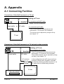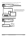
1
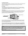
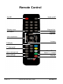
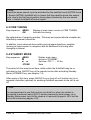
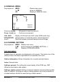
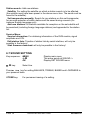
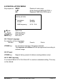
Intelligent Satellite Receiver
System for Motor Homes and
Caravans
Operating Instructions
GB
Important Notes:
Please read these operating instructions before installation and start-up of your
AutoSat2.
Always make sure (even when your AutoSat2 will be retracted by your
starter key, see chapter 4.2 Power Supply) that the system has really
retracted when starting your vehicle. In case of interrupted supply
voltage, for instance, the aerial can no longer be automatically retracted.
Very important: The external unit must be assembled in stationary position
with the aerial folded in a direction opposite to driving direction on the vehicle
roof as otherwise one cannot rule out that the aerial will be righted by the wind
during high-speed driving.
When loading the vehicle on a train, the aerial must be fixed in stationary
position by additional suitable means (expander belts, etc.), due to railway
wagons being turned around when recoupling.
Do not clean your AutoSat2 external unit with a steam cleaner. The rubber
seals used for sealing will be OK for rain and water spray but cannot survive a
water jet of several bars of pressure.
Do not use drive-in wash stations, which will be used entirely at your risk.
A condition for satellite reception will be free sight to the satellite, i.e. trees for
instance cannot be penetrated by a satellite signal !!
In European marginal zones you may not be able to receive all your stations.
Therefore ensure that satellite search in these areas operates with a station
receivable there
WARNING:
In order to prevent damage to your vehicle roof, your AutoSat2 must not be
operated in high winds and gusts.
PAGE 2
OPERATING INSTRUCTIONS
AUTOSAT 2
Contents
I. ASSEMBLY INSTRUCTIONS ........................................................................ 4
1.0 Scope of Supply........................................................................................ 4
2.0 Selection of Installation Site ...................................................................... 4
2.1 Receiver................................................................................................. 4
2.2 External Unit .......................................................................................... 5
3.0 Mounting the External Unit........................................................................ 6
4.0 Cable Connection to AutoSat2 Receiver ................................................... 7
4.1 External Unit .......................................................................................... 7
4.2 Power Supply......................................................................................... 8
CONNECTING DIAGRAM ................................................................................ 9
REMOTE CONTROL ...................................................................................... 10
II. OPERATING INSTRUCTIONS.................................................................... 11
5.0 General................................................................................................... 11
5.1 Enabling............................................................................................... 11
5.2 Procedure for Automatic Satellite Search............................................. 11
5.3 How To Select a TV or Radio Station................................................... 12
5.4 Volume Control .................................................................................... 12
5.5 OK-Key: Information on Broadcasts ..................................................... 12
6.0 Explanation of Menus ............................................................................. 13
6.1 MAIN MENU ........................................................................................ 13
6.2 SEARCH SATELLITE .......................................................................... 13
6.3 FINE TUNING ...................................................................................... 14
6.4 STANDBY MODE ................................................................................ 14
6.5 MANUAL MENU .................................................................................. 15
6.6 CHANNEL SETTING ........................................................................... 15
6.7 SOUND SETTING................................................................................ 16
6.8 INSTALLATION MENU ........................................................................ 17
7.0 Special Functions ................................................................................... 18
7.1 LIST Key: Station List........................................................................... 18
7.2 STANDBY Key..................................................................................... 19
7.3 SAT Key: Changing the Satellite .......................................................... 19
7.4 AUDIO Key: Selection of Languages ................................................... 19
7.5 ON/OFF Key at Front of Unit: Additional Function................................ 19
7.6 #-Key: Adjusting the HF-Modulator ...................................................... 19
A. APPENDIX ................................................................................................. 20
A.1 Connecting Facilities .............................................................................. 20
A.2 Brief Operating Instructions .................................................................... 22
A.3 Faults and Remedies.............................................................................. 23
A.4 Specification ........................................................................................... 24
AUTOSAT 2
OPERATING INSTRUCTIONS
PAGE 3
I. Assembly Instructions
!!! Note
Please read these assembly instructions before commencing installation!
1.0 Scope of Supply
1 Receiver with integrated motor control and IR remote control
1 External unit and satellite aerial (dish or flat aerial)
1 Connecting cable for power supply, 1 m length
1 12-way connector housing
1 Assembly material for satellite aerial
self-tapping screws 3.9x25
1 Junction box
1 Support block for dish aerial or
sealing cap (Waterlock) for plug of flat aerial
2.0 Selection of Installation Site
2.1 Receiver
Initially select site for positioning your receiver. It should be close to your TV
set, if possible and be seen from where you sit, due to the receiver being
controlled by an IR remote control.
!!! Note
When using a separate control with an integral IR receiver supplied as an
option, the receiver may also be concealed in a cabinet.
Please pay particular attention to:
Sufficient ventilation for the receiver, no additional heat sources inside a
cabinet.
The need to reach the receiver conveniently with the necessary cables.
Supply of short screws (max. 7 mm depth into the unit), should the
receiver have to be fastened directly to the housing and in original
bores only.
PAGE 4
OPERATING INSTRUCTIONS
AUTOSAT 2
2.2 External Unit
When selecting the installation site, please notice that cables to the external unit
are 4 (6) m long and ensure that the external unit will have a sufficient
clearance for rotation.
Flat aerial:
The AutoSat2 (50 cm flat aerial) has a base of 41.5 x 41.5 cm and in search
mode will require a maximum radius of 25 cm for objects of up to 15 cm height.
For higher objects, a radius of 45 cm will have to be reserved.
Dish aerial
The AutoSat2S (85 cm dish) has a base of 41.5 x 41.5 cm and in search mode
will require a free area of 45 cm radius, due to the LNB, for instance, rotating
just above the roof in Northern Europe. In stationary position, the space
required is shown in the following sketch:
Aerial
Driving direction
Base plate
Support block
41.5cm
r = 45cm
41.5cm
105cm
Now find sufficient free space on your roof around the cable gland. The direct
vicinity of the site selected must be free from high objects (exceeding 20 cm),
which might shadow the aerial.
When this installation site has been found, once again make sure whether the
receiver is within a cable length of 4 (6) m. If not, relocate the installation site or
the receiver or extend the cable by an additional extension set (obtainable from
us).
!!! Note:
Mount and secure the external unit in such a way that detachment or falling
down of the unit is impossible. For sandwich roofs not offering adequate
facilities for assembly, a through-screw and an internal doubler plate is
recommended.
In case of doubt consult the maker of your vehicle.
AUTOSAT 2
OPERATING INSTRUCTIONS
PAGE 5
3.0 Mounting the External Unit
Proceed in the following sequence
Use Sikaflex-252 as an adhesive/sealant
1.
Position external unit with the outgoing cable pointing towards the rear of
the vehicle.
2.
Drill 2 diagonal holes from the base plate of the external unit by using a 2.4
mm drill.
3.
Fix external unit by two self-tapping screws of 3.9 x 25 to the roof. Lightly
tighten screws. The aluminium coating of the roof is thin and the
screws may be easily tightened too hard. Then drill remaining holes.
4.
Lift off external unit and clean underside and edges of base plate as well as
the roof mounting area from dirt and fatty residues. Fully coat base plate
with a thin coating of Sikaflex-252 and position external unit on roof in
chosen position.
5.
Before turning in the screws, seal holes with Sikaflex. Arrange a sealing
joint around edge of base plate.
6.
Drill a hole (min. dia. 15 mm) for the three cables through the roof.
7.
Wrap cable contacts with adhesive tape to avoid damage. Carefully push
cables from side into junction box and through roof. Fix junction box over
this hole with Sikaflex-252 and 3 bolts of 3.9 x 25.Position and fix cables to
roof. It is recommended to use a cable trunking 20 x 20 mm, attached to
the roof by Sikaflex-252.
8.
The aerial can only be mounted after the system has been connected to
the power supply and is ready for operation, as the arm of the aerial will
have to be extended from stationary position. Switch on AutoSat2, wait until
arm has sufficiently extended and interrupt power supply (remove cable).
Use washers for all four screws.
8.1 Flat aerial: Carefully tighten nut of aerial cable on aerial by a 11mm openended spanner but not too tightly.
8.2 Dish aerial: After assembly of aerial dish, fasten support block, whilst
the aerial is in stationary position, below free end of aerial dish.
This concludes work on the roof.
PAGE 6
OPERATING INSTRUCTIONS
AUTOSAT 2
4.0 Cable Connection to AutoSat2 Receiver
4.1 External Unit
Lay cables from external unit to receiver. Cables may not rub against sharp
edges or be laid close to heat sources. Ensure prior to engaging contacts in
connector housing that contacts are in faultless condition and not bent. In
particular, contact blades must not have excessive spacings. Engage
contacts in connector housing to the following sketch. Individual cable cores are
marked in colours and connector-housing recesses are numbered to eliminate
confusion.
Work very carefully, because contacts, once inserted, cannot be removed.
Ensure that contacts are fully inserted to allow blade to engage (can be heard
as a click). After inserting all contacts, push connector housing together in
vertical direction to contacts.
Sketch of connector housing (rear view!!)
3-core cable:
6-core cable:
brown (thin)
pink
green
yellow
grey
white
brown (thick)
7
1
8
2
9
3
10 11 12
4
5
blue
6
black
For power supply connection see next page
AUTOSAT 2
OPERATING INSTRUCTIONS
PAGE 7
4.2 Power Supply
Proceed in accordance with wiring diagram on following page. Connect short 3core connecting cable supplied by a suitable connector to your 12 V vehicle
mains.
For a 24 V vehicle mains, a 24V/12V transformer will be required.
Use a cable section of min. 4 mm2 for voltage supply to keep cable losses to a
minimum. The AutoSat2 should ideally be directly connected to the battery by a
dedicated supply cable. Ensure that no other major users are connected to the
same supply cable. If so, the cable section must be of a suitable larger size.
Connect blue cable of 1 mm2 to terminal 15 (ignition on) and/or D+ (alternator).
This will ensure automatic retraction to stationary position of the unit when
starting to drive. Both a 12 V and 24 V signal may be connected in this case
(applicable to control cable D+ ONLY).
Always ensure that system is fully retracted when starting to drive. When
the power supply is interrupted, the automatic mechanism will be unable
to retract the aerial.
The system is equipped with a polarity reversal protection system.
Please use your AutoSat2 only connected to a battery and/or to a stabilized and
regulated DC power supply with at least 10 A continuous current.
PAGE 8
OPERATING INSTRUCTIONS
AUTOSAT 2
Connecting Diagram
External unit
TV connection
HF modulator
VCR scart connection
Aerial
Motor control
CRYSTOP
RS232
Made in Germany
TV
LNB
VCR
R
TV
TV scart
connection
L
Audio
Decoder
Audio outputs
Left/right channel
Control incl. IR receiver
(optional)
Aerial
Input
IR Sensor + 12V - D+
External Unit
Decoder
Scart connection
RED: 12V (4 mm²)
BLACK: mass (4 mm²)
Blue: D+ or terminal 15
Connecting facilities for TV with/without a scart and video recorder see
appendix A.1.
AUTOSAT 2
OPERATING INSTRUCTIONS
PAGE 9
Remote Control
On/Off
Audio on/off
Display menu
Exit menu
Channel list
Channel
selection
Menu operation
Volume
TV/Radio
TV: Exit all menus
1st channel of
actual satellite
Mono / Stereo
Astra1 <-> Astra2*
Menu background
Save settings
PAGE 10
Standby
OPERATING INSTRUCTIONS
AUTOSAT 2
II. Operating Instructions
5.0 General
AutoSat2 DVB offers digital channels of factory preset or personally
programmed satellites of the satellites ASTRA 1, HOTBIRD and ASTRA 2.
5.1 Enabling
Please enable your TV first to enable On Screen Display of your AutoSat.
AutoSat2 On: Use centre key at front of unit or key at separate controller
(optional) only.
AutoSat2 Off: Use centre key at front of unit or key at separate controller
(optional) or ON/OFF key on remote control.
After enabling the unit, an automatic search will be started with your last
selected channel active. No further operation will be necessary for
automatic search except you want to change the channel or satellite.
AutoSat2 will be displayed and the aerial is extended to start extension (green
screen).
During this phase only, the search procedure may be interrupted in order
to change channels or to select satellite (see chapter 5.3 or 6.2):
Possible keys for manipulation are:
,
1 change of channel
0…9
Channel direct input
LIST
Channel list
MENU
Search satellite
followed by the search being automatically continued.
During satellite search, AutoSat2 will not react to remote control (except
the ON/OFF key).
5.2 Procedure for Automatic Satellite Search
The search may comprise up to 2 passes, with the second pass searching at a
higher sensitivity until the satellite has been found.
After rough location of a satellite, fine tuning will start, with the system
searching for optimum reception. This may take more or less time depending on
the quality of reception and/or the selected station.
Fine tuning may be aborted by pressing any key. In case of abortion, no
optimum image may be ensured for all channels.
AUTOSAT 2
OPERATING INSTRUCTIONS
PAGE 11
5.3 How To Select a TV or Radio Channel
Channel selection is effected by the following keys:
-
,
keys
-0…9
- LIST
- TV, RADIO
Press briefly: 1 change of channel
Press and hold: fast channel changes
Channel direct input, 1, 2 or 3-digit.
For input of multi-digit numbers enter figures fast.
Station list, see chapter 7.1
Switch TV <-> Radio
5.4 Volume Control
Set volume by
and
keys.
Press STORE key (whilst VOLUME is inserted) for permanent storage of setting
Set volume at TV Set to higher range (not maximum), save this setting and
adjust AutoSat2 volume to your personal taste.
5.5 OK-Key: Information on Broadcasts
Press OK-key to obtain information on present and following broadcast (not
always available). Sometimes there is additional information available on 2nd
press of OK-key. Follow top line of screen for further information. Possible only
when no menu has been selected.
PAGE 12
OPERATING INSTRUCTIONS
AUTOSAT 2
6.0 Explanation of Menus
6.1 MAIN MENU
After pressing the MENU key, the main menu will be displayed.
MAIN MENU
,
AUTOSAT:
Search satellite
Fine tuning
Standby:
OFF
Manual
see chapter 6.2
see chapter 6.3
see chapter 6.4
see chapter 6.5
RECEIVER
Channel setting
Sound
Installation
see chapter 6.6
see chapter 6.7
see chapter 6.8
key:
Select desired sub-menu or function. The submenu or function will be marked by the arrow.
Activate sub-menu or function
Exit main menu or sub-menu
OK key:
MENU key:
6.2 SEARCH SATELLITE
Should the AutoSat2 not have found the required satellite based on the same
transponder frequencies of more than one satellite, the search may be
continued with this function.
As well another satellite may be searched as follows:
Key sequence: MENU
OK
Display main menu
Arrow pointed at SEARCH SATELLITE
The SEARCH SATELLITE menu will be displayed
SEARCH SATELLITE
ASTRA 1
HOTBIRD
ASTRA 2
, key:
OK key:
Select desired satellite
Start search
AUTOSAT 2
OPERATING INSTRUCTIONS
PAGE 13
!!! Note:
Should the same search cycle be activated for the satellite found (ASTRA found
-> Search ASTRA) AutoSat2 will no longer find this satellite during this search
cycle, due to the first found position having been blocked by the new search
cycle -> Switch AutoSat2 off and on again.
6.3 FINE TUNING
Key sequence: MENU
OK
Display of main menu, arrow on FINE TUNING
Activate fine tuning
Re-optimisation of receiving position. This may be required should reception be
affected by external influences.
In addition, some channels have mildly varying beam directions, possibly
causing an improvement in reception with an additional fine tuning after
changing a channel.
6.4 STANDBY MODE
Key sequence: MENU
,
STORE
Display main menu
Arrow on STANDBY
Set time: OFF 1 … 30 hrs.
Save
The period of time may be set here, within which the AutoSat2 may be reactivated by the ON/OFF key of the remote control after activating Standby
Mode (STANDBY key, see chapter 7.2).
After expiry of this time, press ON/OFF key on front of unit (centre key) or on
separate controller (optional) for enabling AutoSat2 as power to the unit is cut
off.
!!! Note:
It is recommended to use this function only briefly or when the vehicle is
connected to external mains (220 V) and/or powered by solar power, as in
Standby Mode power input to the receiver is reduced by approx. 50% but the
unit is still consuming approx. 8 W.
PAGE 14
OPERATING INSTRUCTIONS
AUTOSAT 2
6.5 MANUAL MENU
Key sequence: MENU
2x
OK
Display main menu
Arrow on MANUAL
Display of MANUAL menu
AUTOSAT manual
Aerial :
Key
:
:
:
POS:
ELE:
AZI:
C/N / AGC
Press key briefly
Press + hold key
C/N / AGC:
POS ELE/AZI:
Key C:
…degrees
…degrees
Movement in small increments
Continuous movement
Display of C/N and tuner AGC value (DVB mode only).
Aerial position in horizontal and/or vertical alignment.
Switches between coloured background and image
6.6 CHANNEL SETTING
Key sequence: MENU
3x
OK
Display main menu
Arrow pointing to CHANNEL SETTING ->
Display of DVB MAIN MENU
DVB MAIN MENU
Possible keys for operation are displayed on the screen. The bottom line of the
display shows information applicable to the selected menu item.
Station information: Shows information for currently selected station.
Index: General Index
Settings, general: For setting the screen display of the DVB logo, GMT
difference and station data update.
Settings, station search: Setting of required satellites and associated symbol
rates. In addition, this may be used for setting whether only freely available or
encoded stations should be saved during a station search.
AUTOSAT 2
OPERATING INSTRUCTIONS
PAGE 15
Station search: Add new stations
Satellite: For setting the satellite on which a station search is to be effected
(the satellite must have been preset in the above menu item. The aerial must be
tuned to the satellite).
Set transponder manually: Search for any stations on this set transponder,
for accurate selection of which stations will be saved during a search (for
instance English language only).
Add new stations: All stations available for reception on the set satellite will
be searched (including foreign language stations) and appended to the station
list.
Service Menu:
Service Information: For obtaining information of the DVB module, signal
amplitude and C/N.
Edit station lists: Transfer of station lists by serial interface, will only be
possible in the factory!
Start firmware download: will only be possible in the factory!
6.7 SOUND SETTING
Key sequence: MENU
4x
OK
,
key:
Display main menu
The arrow points at SOUND ->
Display SET SOUND menu:
Select line
Press
or
key for setting BALANCE, TREBLE, BASES and LOUDNESS to
your personal taste.
STORE key:
PAGE 16
For permanent saving of a setting.
OPERATING INSTRUCTIONS
AUTOSAT 2
6.8 INSTALLATION MENU
Key sequence: MENU
5x
OK
Display of main menu
Arrow points at INSTALLATION ->
Display of INSTALLATION menu:
INSTALLATION
, key:
,
key:
STORE key:
MENU key:
Language:
Preset:
English
STORE
LNB frequency:
9.75 / 10.6
Select line
Change setting
Store settings
Exit menu
6.8.1 Select Language
For selection of four languages:
German
English
STORE key:
French
Dutch
For permanent storage of language selected.
The sequence of stations will be reprogrammed according to
national usage.
6.8.2 Preset
STORE key:
Repeat factory preset of stations (analog stations only!).
6.8.3 LNB Frequency
A universal LNB of 9.75-/10.6 GHz LOF is used as a standard setting. This may
not be altered.
AUTOSAT 2
OPERATING INSTRUCTIONS
PAGE 17
7.0 Special Functions
7.1 LIST Key: Station List
After pressing the LIST key, a list of stations saved will be displayed. The
present station is marked by an arrow / highlighted.
,
key
, key
OK key
Random key
Page forward and/or backward
Select station
Change to selected station
Exit without changing station
DVB mode:
A key
Sorting / deletion of stations
B key
Individual volume setting for each station
C key
Change name of station
Follow screen display for operation
Analog Mode:
List key
Change from TV to radio list and vice versa
Radio stations are marked by a note symbol.
PAGE 18
OPERATING INSTRUCTIONS
AUTOSAT 2
7.2 STANDBY Key
Switch AutoSat2 to Standby mode by pressing the STANDBY key.
The aerial will remain in receive position and the receiver will switch off (display:
OFF). There is no power consumption in this condition. However, the
AutoSat2 may not be switched on by remote control but only at front of unit. To
remind you that the aerial is extended, an LED will flash on the front of the unit
and the separate controller (optional). Power consumption of this LED is
negligible (0.1 W).
There is also a facility for switching the AutoSat2 to Standby, with the aerial
remaining extended and the TV image disappearing. However, the AutoSat2
may be re-activated by remote control (ON/OFF key) (the unit is under power:
8 Watts !). The time during which the AutoSat2 may be re-activated may be
permanently set once by the STANDBY menu (chapter 6.4) or by pressing the
STANDBY key several times. After expiry of the set time, AutoSat2 will
automatically switch off its power supply. Press ON/OFF key at front of unit or
on separate controller (optional) to enable AutoSat2 again.
7.3 SAT Key: Changing the Satellite
Holding the SAT key will change AutoSat2 from the ASTRA 1 satellite to the
ASTRA 2 satellite and vice versa (ASTRA 2 to ASTRA). This is subject to you
just receiving one of the satellites and the other satellite also being available for
reception at your location.
7.4 AUDIO Key: Selection of Languages
Press the AUDIO key to select language of multi-lingual broadcasts.
Press the AUDIO key to select mono or stereo.
7.5 ON/OFF Key at Front of Unit: Additional Function
Whilst the unit is switched on, additional functions such as Fine Tuning and/or
Search Satellite (same function as in menu) may be activated. (Press ON/OFF
key until insert appears on screen). This additional function is provided in case
the remote control should be relocated or fail.
7.6 #-Key: Adjusting the HF-Modulator
Press and hold the #-key allows adjustment of the modulator channel, should
your TV unit have been connected to the AutoSat2 by a coaxial cable (we
recommend connection by a Scart cable, as this will clearly improve your image
quality). Set channel from 21 to 69 by using the or key. The presently set
channel (channel 38 ex works) will be shown at the front of the AutoSat2. The
and
key alters the sound carrier from UK to German mode and vice versa.
Use STORE key for permanent saving.
AUTOSAT 2
OPERATING INSTRUCTIONS
PAGE 19
A. Appendix
A.1 Connecting Facilities
Connection of AutoSat2 receiver to a TV set
Setting at TV set:
VCR
TV
R L
TV
AutoSat2
Audio
For connection by SCART-cable:
Switch TV to AV or channel 0
Scart-cable
or
HF-cable
For connection by HF-cable:
Tune TV set to preset AutoSat channel (see
specification: TV connection HF-modulator).
The channel may be adjusted by using the # key:
see chapter 7.6.
TV set
Connection of AutoSat2 receiver to a TV set and a video recorder
Setting at TV set:
VCR
TV
R L
TV
For connection by HF-cable:
AutoSat2
Audio
Scart-cable
HF-cable
HF-combiner
DM44
Tune TV set to preset AutoSat channel (see
specification: TV connection HF-modulator).
The AutoSat channel may be adjusted by using
the # key: see chapter 7.6.
In this configuration the VCR may record from
AutoSat by Scart-cable. Playback is possible
via Scart by switching AutoSat channel 0 or via
HF-cable without AutoSat being activated.
TV set
VIDEO RECORDER
PAGE 20
OPERATING INSTRUCTIONS
AUTOSAT 2
Connection of AutoSat2 receiver to a TV set and a video recorder
Setting at TV set:
VCR
TV
R L
TV
For connection by SCART-cable:
AutoSat2
Audio
Switch TV set to AV or channel 0
Scart-cable
In this configuration the VCR may record from
AutoSat by Scart-cable. Playback is possible
via Scart by switching AutoSat channel 0 or via
HF-cable without AutoSat being activated.
HF-cable
Scart-cable
TV set
VIDEO RECORDER
Connection of AutoSat2 receiver to a stereo set
VCR
R L
TV
TV
AutoSat2
Audio
Stereo cinch cable
Aux In
Line In
STEREO AMPLIFIER
AUTOSAT 2
OPERATING INSTRUCTIONS
PAGE 21
A.2 Brief Operating Instructions
Function
Operation
Enable
Only by pressing the ON/OFF key at front of unit or
on separate control (optional)
Disable
ON/OFF key at front of unit or
ON/OFF key on remote control
Standby
STANDBY key
Change station
,
,
key on remote control
key at front of unit
Direct station
selection
Keys 0 … 9
Enter 1, 2 or 3-digit figures
Select station
from list
LIST key: The station list is displayed
, , ,
key: Select station
OK key: Change to selected station
Random key: Return - no change
TV <-> radio
Radio or TV key
Information
OK key: Information on present / following broadcast
Volume
,
key: To change volume
STORE key: Save setting (while volume is displayed)
Main menu
MENU key
, key: Select function / sub-menu
OK key: Activate function / sub-menu
,
key: Change settings
STORE key: Save settings
MENU key: Exit menu
Search satellite
Automatically after activating the unit or
MENU key -> SEARCH SATELLITE or
SAT key: Change ASTRA 1 -> ASTRA 2 and vice versa.
Fine tuning
Automatically after satellite has been found or
MENU key -> FINE TUNING
PAGE 22
OPERATING INSTRUCTIONS
AUTOSAT 2
A.3 Faults and Remedies
Fault
Remedies
No satellite found
1) Check whether sight is free in southerly direction.
There will be no reception under trees!
2) There is no transmission on your selected station, try
another station for search.
3) Whilst moving about in marginal European areas: for
searching switch to a station, which can be positively
found.
4) Check aerial cable to external unit (firm attachment of
connector, cable break)
1) Check connection to TV set.
2) Should your TV set be connected via an HF cable,
check setting on TV set (channel position).
3) For connection by SCART cable, switch TV set to AV
(or channel 0).
1) Repeat satellite search:
MENU key -> SEARCH SATELLITE
Aerial in position
but no image
Incorrect satellite
found
1) Perform FINE TUNING from main menu.
2) Your are in the marginal area of the satellite’s
coverage
3) Should 2) not apply, check aerial cable (for firm
attachment of connector)
Motor cannot turn 1) Check whether external unit is free to move.
2) Check connectors of motor cable for firm attachment.
All contacts must be firmly attached to recesses in
connector housing.
1) Check whether external unit is free to move.
Motor overload
protection
Inferior image
quality
Unit switched off
immediately
1) Check battery voltage
2) Your vehicle has been started
Inexplicable
malfunctions
1) Switch AutoSat2 off and on again.
2) Temperature too high, let AutoSat2 cool down
(perhaps there is not enough ventilation / another heat
source nearby)
AUTOSAT 2
OPERATING INSTRUCTIONS
PAGE 23
A.4 Specification
Power supply
Supply voltage
Supply voltage control line D+
Current / power input
Search mode typ.
Reception mode typ.
Standby mode typ.
Current limit, motors
LNB control
10…16 V DC
10…30 V DC
Approx. 3 A / 36 W
1.2 A / 15 W
0.8 A / 10 W
approx. 8 A
14/18 V, 300 mA max.
22 kHz, Toneburst
LNB
LOF
Noise level low / high band single LNB
twin LNB
9.75 / 10.6 MHz
0.9 / 1.1 dB typ.
1.0 / 1.2 dB typ.
TV Connection SCART TV
Video
Output level
Audio, 2 channels, R, L
Modes
Output level
CCIR, 625 lines
1 Vss to 75 Ohms
Mono A/B, Stereo
0.5 V eff.
TV connection HF-modulator
Setting range
Presetting
Output level
Output impedance
Channels 21…69
Channel 38
72 +/- 4dBµV
75 Ohms
VCR Connection via SCART VCR
Video/audio output
Video input
Audio
PAGE 24
See SCART TV connection
FBAS, 1 Vss to 75 Ohms
R, L, approx. 0.5 eff.
OPERATING INSTRUCTIONS
AUTOSAT 2
CINCH connections
AUDIO L/R
AUTOSAT 2
Audio left / right
see SCART TV connection
OPERATING INSTRUCTIONS
PAGE 25
CRYST P
O
Gesellsc h a f t f ü r A n z ei g esy st em e m b H
Durlacher Allee 47
76 131 Karlsruhe
: 0721 / 61 10 71
: 0721 / 62 27 57
www.crystop.de
Subject to alterations without notice for performance improvement
PAGE 26
OPERATING INSTRUCTIONS
10/04
AUTOSAT 2