1
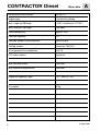
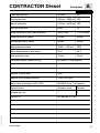
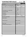
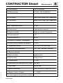
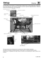
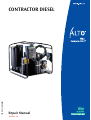
www.alto-online.com
125 03 47 (03.2003)
CONTRACTOR DIESEL
Repair Manual
2003-11-14
ALTO Danmark A/S
Industrikvarteret
DK-9560 Hadsund
Tel.: +45 7218 2100
www.alto-online.com
Copyright © 2003
ALTO Danmark A/S
A
Technical data
B
Structure
C
Function
D
Trouble-shooting
E
Service / Repair
F
Test / Adjustment
G
El. diagrams
H
Spare parts proposal
I
(Info & spare parts)
INDEX
CONTRACTOR
Diesel
Petrol
CONTRACTOR Diesel
4
Motor data
Diesel motor RUGGERINI
MD 151, S
Engine type
4 stroke two cylinder
Max. output at 3600 rpm
13 HP / continuous 12.3 HP
Max. torque st 2400 rpm
3.26 Kgm
Fuel consumption
Approx. 3 l/h
Fuel tank capacity
4.1 l
Adjusted speed at max. pressure
3500±10 rpm
Cooling system
Forced air 700 m3/h
Air requirement for combustion
62 m3/h
PTO shaft rotation
clockwise
Max. vacuum intake
0.024 bar
Max. exhaust backpressure
0.039 bar
Engine oil capacity / type
1.8 l / SAE 15 - 50
Dry weight
50 kg
A
D_CON. 03GB.
CONTRACTOR Diesel
Pump data
A
Heavy Duty
210 bar
225
Pump pressure
180 bar / 2550 psi 205
Nozzle pressure
170 bar / 2410 psi 195
By-pass pressure
8 bar
10
Water quantity at min./max. pressure
20/19 l/min.
17.5/16 l/min.
Water quantity at steam
9 l/min.
8 l/min.
Pump pressure at steam
40 bar
30 bar
High pressure nozzle
1506 = 1.35 mm
1505
Max. temperature of inlet water
35°C
35°C
Inlet pressure, max.
10 bar
10 bar
Chemical injector (external only)
03 injector / foam injector
Density (control box)
IP45
Engine r.p.m. (pump pressure)
1750 ± 25 r.p.m.
Noise level according to ISO 3746
85 DB(A) from 7 m distance
Type of piston
Stainless steel
Ceramic
Wobble disc no.
7
3
Type of oil
BP Bartran HV 100
125 03 47 - (03.2003)
Opening pressure
D_CON. 03GB.
5
CONTRACTOR Diesel
Boiler data
A
Heavy Duty
Boiler effect
6
115 kW
100
Water outlet temp. at max. water quantity (12°C) 95°C (205°F)
=
Oil consumption at max. water quantity and temp. 12 l/h
10 l/h
CO2
10-12%
=
CO
50-100 ppm
=
Temp. flue gas at 20°C ambient temp.
160-200°C
=
Smoke scale number
Max. 1
=
Flue gas loss
Max. 10%
=
Oil nozzle type
9 kg/h - 60°S
=
Oil pressure
12 bar
11 bar
Boiler tube / measurements
Welded st. 35.8 / 20 x 3mm x 48m
Heating surface
3 m2
Quantity of inlet air
Approx. 180 m3/h
Outlet flue gas
260 m3/h at 200°C
Tank capacity max./min. Jerry can
20 l / 3 l
D_CON. 03GB.
CONTRACTOR Diesel
Electrical parts
A
A1 KEW-steering
24V AC 642009A
A2 KEW-converter
12V DC / 24V AC 6420013
B1 Flow control
After pump magnet oper. Reed-switch
B2 Flow control
Before boiler magn. oper. Reed-switch
B4/B5 Temperature sensor
PT500
B6 Flame sensor
Light-sensitive transistor
B67 Motor oil switch
Open at a normal oil pressure
F1 Fuse on print A2
1 AT
F2 Fuse on print A2 *)
6.3 AT
F3 Fuse for PC-board A1 (see page 5)
1.25 AT
F4 Fuse for start protection (see page 5)
1.25 AT
G1 Accumulator battery
12V min. 50 AH (300 Amp.)
G2 Generator internal/external
12V - 15V - 280 Watt / 300 Watt
G3 Regulator/Rectifier
H1 Motor oil alarm
Lamp on front
H2 Starting relay
Lamp on front
M1 Starting motor
1.1 kW
R1 Resistance (only where B5 is not used)
560 ohm
S1 Start switch
Key on front
T1 Ignition transformer
Prim: 2x12VAC/17 Amp. Sec. 11KV
125 03 47 - (03.2003)
Y1 Magnet valve for oil pump
24 VAC
F3 *) secure against fault polarization of battery
D_CON. 03GB.
7
Setup
Structure
B
The Contractor is constructed on a combined pipe and plate frame, surface coated with a strong polyester. Each single item of the machine is placed in a way that an optimum weight distribution is obtained
taking service and operation into consideration.
Temperature indicator
Front panel
Temperature regulation
Ignition key
Control lamps
H1 H2
Starter battery
Chemicals container rack
Exhaust outlet from boiler
Ignition transformer
Electrics box
Exhaust from motor
Manometer for HP-pump
Pump oil
Diesel tank for motor
Fuses
F3
F4
Back of electrics box
Motor suspension
The base plate for the motor/pump unit is mounted on 4 inclined vibration absorbers.
The boiler is mounted on a plate construction, which serves as air duct from blower to boiler.
Electrics box is suspended in the pipe frame and contains the controlling and safety system of the
machine
8
D_CON. 03GB.
Setup
Structure
B
Pump front
Manometer
Water quantity regulation
Water inlet
Water outlet
Flow switch B1
Pressure outlet
Electromagnet Y2 Y3 (safety stop)
Sludge glass
Starter relay
Starting motor
Gearbox
Diesel oil for pump
Motor connection (- pinch)
Oil pressure
switch B7 Rectifier G3
Motor air filter
Blower
Flow
switch B2
Solenoid
valve Y1
125 03 47 - (03.2003)
Flexible coupling
Fuel oil pump
D_CON. 03GB.
Air adjustment screw
Flow switch B2
9
Boiler
Structure
B
The boiler is the heat generating part of a hot water machine. It consists of a labyrinth-constructed
tube coil, which encloses the combustion chamber.
The tube coil is enclosed by a double container with boilerjacket, bottom, and top in a sandwich construction, between which the combustion air is pressed into the combustion. An insulating material
placed in the bottom of the boiler makes sure that the inner bottom, among other things, is protected
from superheating.
Gasket
Exhaust gas
Electrodes
Flame sensor
Oil nozzle
Flame tube top part
Air distributor
Burner tube
Inner jacket
Outer jacket
Flame tube bottom part
Insulating mat
Air duct
Water inlet
Gasket
Air inlet
Water outlet
A flame tube consisting of two rings has the purpose of securing that the hot exhaust gases are forced
round the labyrinth of tubes.
The boiler is mounted on the air duct with a gasket between and fastened with 3 bolts. In the air duct
an adjustable throttle is mounted.
10
D_CON. 03GB.
Pump
B
Structure
The pump is a 4 cyl. axial pump model 03 with standard sealing system and steel pistons, or model C3
with textile seals and and ceramic pistons.
The pump is driven by the motor through a gear, which reduces the number of revolutions of the spindle
from 3500 rpm to 1750 rpm.
Gear wheel
Gasket
Roller bearing
Cylinder cover
Oil glass
Pistons
Clamping ring
Valve cylinder head
Pressure valve
By-pass valve
Non return
valve
Pressure outlet
Safety valve
Suction valve
Oil seal
Wobble disc
Oil seals
Pressure seal
Oil drain
Suction seals
Motor shaft
Valve piston
D-cover
Oil drain
Sludge container
Standard
HD
C3
Drain channel
WOBBLE DISC
Standard
HD
No. 7
No. 3
Textile seal
125 03 47 - (03.2003)
Oil seal
Back-up seal
D_CON. 03GB.
11
Operating diagram
Function
C
When the Contractor is running, the fan draws in air and leads it through a channel with an air volume
adjustment and into the bottom of the boiler, around and between the two jackets up to the air distributor.
In this way the air is preheated, before it is mixed with the oil spray from the nozzle.
Fuel nozzle
Air distributor
Fuel tank
Fuel filter
Fan
Magnet
valve
Air
in-take
Fuel pump
Max
Insulation
Air adjustment
Oil pressure damper
The fuel is drawn from the jerry can through the fuel filter to the pump, while in hot mode it is passed
through the magnetic solenoid valve to the nozzle in the air distributor.
The ignition transformer is active for approx 6 sec., and during this period it will form sparks between
the electrodes.
If the flame is not developed within this time, a flame sensor placed on top of the boiler will secure that
the machine is automatically stopped.
When the machine is running normally, and the boiler is burning normally, the flame is pressed against
the insulated bottom. The temperature is here approx. 1100°C. The hot exhaust gas is pressed further
round the labyrinth-shaped combustion chamber, where the heat is absorbed by the water flow in the
tubes.
12
D_CON. 03GB.
Operating diagram
Function
C
The flow system is simple with direct water inlet to the pump (water tank can be mounted), on which an
adjusting screw permits infinitely variable regulation of the water quantity. From the pump the water passes two flow controls, before it flows through the approx. 30 m pipe line of the boiler. On the outlet pipe
the temperature sensors are placed (2 sensors are mounted, where priming safety is necessary).
B5
Water inlet
BOILER
Water quantity
regulation
Y1
B3
Pressure water outlet
B1
B7
B2 B4
Water outlet from
the machine
The flow switch detects whether there is water and thereby a flow in the system.
If one of the flow switches disconnects because of a failing flow, the oil supply
will be shut off after 4 seconds.
B4, B7 temperature
sensors
The temperature sensors are PT500 elements sensing the water temperature at
the outlet of the boiler. The function of the sensors is, in a cooperation with the
electronics, to check the outlet temperature of the water compared to the preset
value, see also page 12.
B5 flame sensor
The flame sensor is a light-sensitive transistor mounted at top of the boiler. Its
function is to detect whether the flame is on. If the burner does not ignite, the
engine will stop within approximately 5-10 sec. In order to start the engine again,
turn the ignition key in position „off“.
Y1 magnet valve
On the fuel oil pump the magnet valve Y1 is controlling the injection of oil into the
boiler and by that the temperature. Y1 opens to the fuel oil, when B1 and B2 are
activated at the same time, and the temperature setting is higher than the actual
water temperature on the outlet from the boiler.
125 03 47 - (03.2003)
B1, B2 flow switch
D_CON. 03GB.
13
Operating diagram
Function
C
The controlling and safety system of the Contractor consists of the PC-board A1, the main task of which
it is to secure operation and safety of the boiler system. The PC-board A2 is a conver ter, the main tasks
of which it is to convert 12 V DC to 24 V AC and to supply the ignition transformer with 2x12V AC.
A1
KEW control
12V DC/24V AC conver ter
A2
A1
A2
Motor oil switch
B7
F3
Fuse 1AT
F1
F4
8 7 6 5 4 3 2 1
Fuse 6.3A
F2
safe pump oil motor 24V
Fuse 1.25AT
F3
Fuse 10AT
F4
Accumulator 12V
G1
Generator
G2
S6
Regulator / rectifier
G3
Y1
Oil Pressure indicator
H1
Boiler
Charging indicator
H2
Starting motor
M1
Ohmic resistance
T1 R1
A2
Start switch
S6
12V DC from Accumulator
S1/2
Y2 Y3
S3/4/5 2x12V AC to ignition trafo
9 Pole plug on A2
JP1
8/12 Pole plug on A1
X2/3
Charging plug
X4
B7
Ignition trafo
T1
Solenoid valve fuel
Y1
G2
S6
Hold & Draw coil
Y2/Y3
G3
12V
Start Motor M1
Y3
When the motor is running, the generator G2 supplies 12 Volt DC to the conver ter A2, and the conver ter
supplies 24 Volt DC to the control PC-board A1. The motor is automatically stopped at flame failure and
at lack of lubricating oil in the motor.
F1
F2
F3
F4
Fuse on A2
Fuse on A2
Fuse on El-box
Fuse on El-box
B7 Motor oil alert
14
secures the PC-board against too big charging rate
secures against wrong polarization of battery
secures A1 against overload
secures A2 against overload at star ting of motor
The motor oil alert is a pressure gauge mounted on the engine. Usually the
pressure gauge is closed but at a normal oil pressure it will be open. If the
engine runs dry of oil, the switch will close and thereby stop the engine.
D_CON. 03GB.
EL.-control
Function
C
Plug for test box no. 6420100, see page 32.
A1
08
SLOW
150
09
x2
8 7 6 5 4 3 2 1
Temperature range
selector
x2
safe pump
12
oil
motor 24V
9 8
1
x3 x3
B5
B7
B4
B2
B1
The A1 PC-board is supplied with 24V AC from the conver ter PC-board A2, and it is controlling the oil
injection (Y1) into the boiler with a 24V signal of X2, 4 and 5. This on/off signal is e.g. controlled by the
flow controllers B1 and B2, which are each equipped with a Reed switch making contact when there is
a flow through the machine.
If both flow controllers are not making contact at the same time (max. time difference approx. 4 sec.), the
signal for oil injection (Y1) will disconnect and close, until the machine is stopped and restarted.
The temperature regulation is getting information from the temperature sensor B4 (PT500) placed in the
outlet pipe from the boiler and from the adjustable potentiometer placed on the PC-board. The result is
together with B1 and B2 controlling the signal for oil injection (Y1).
A safety thermostat (priming safety) B7 is securing that the machine stops, if the temperature of the
boiler outlet pipe exceeds approx. 173°C. On some machines this additional safety is replaced by a
built-in resistance.
125 03 47 - (03.2003)
The flame super vision circuit is connected to a light sensor B5 (X3.11 and X3.12) in the top of the boiler
and stops the machine under the following conditions:
a)
If a flame has not occured within 5-10 sec. after the thermostat output has closed.
b)
If the flame disappears for more than 5-10 sec. while the thermostat output is closed.
c)
If the flame is present 15-30 sec after the thermostat output has opened.
d)
If a flame breaks out and stays for more than 15-30 sec. while the thermostat output is open.
e)
If the light sensor is short-circuited or disconnected.
D_CON. 03GB.
15
EL.-control
Function
1
KEW 6420013
JP1
2
Starting rev., 24VAC:
Declutching rev., 24VAC:
Temperature range:
Securing of temperature
- ignition transformer:
C
2500 rpm ±10%
2300 rpm ±10%
0-65°C
3
Interrupts at 90°C
±5°C
4
5
6
7
8
9
F1
Connections:
S1:
+battery
S2:
-battery
S3:
ignition transformer
S4:
double wire ignition transformer
S5:
ignition transformer
S5
S3
S4
F2
S1
S2
input from
input from
input from
output to
6420009
output to
input from
output to
input from
input from
1
2
3
4
Pressure switch B7
Safe, X2-8 on 6420009
Pump, X2-6 on 6420009
24VAC (0), X2-2 on
5
6
7
8
9
24VAC (f), X2-1 on
Key, +12V from key
Engine off, Y2 on engine
G2 on engine
G2 on engine
1. The converter is supplied with 12-15 VDC.
2. The converter supplies the control unit 6420009 with 24 VAC/55 Hz, when the engine is running (rpm
> 2500).
3. The conver ter supplies the ignition transformer with 2x12VAC, when the engine is running (rpm >
2500) and there is a signal on „Pump“. The ignition transformer is active for approximately 6 sec.
If new signal displays within the 6 sec., the time will start all over again.
4. The conver ter is protected against polarization errors, i.e. a fuse (F2) will blow if the cables of the
battery are interchanged.
5. The engine is stopped by a signal at the Safe inlet. Disconnect the conver ter (Key off) before
restarting the engine.
6. The engine is stopped by a signal at the inlet of the pressure gauge.
7. The converter features an excess temperature cut-out breaking the voltage for the ignition
transformer at a temperature > 90°C.
Supply voltage:
Outlets:
Supply for KEW 6420009:
Voltage for the ignition transformer:
16
12-15 VDC
24VAC ± 15% 0.5A
55Hz ± 15%
2x12VAC ± 15% 17A
100Hz ± 15%
D_CON. 03GB.
Electric system
G1
G2
G3
M1
S6
Y3/Y2
B7
H1/H2
Function
C
12V start battery
12V generator in motor
charge rectifier
start motor with relay
start switch
pull hold coil for the fuel supply of motor
lubricating oil pressure switch for motor
pilot lamps oil pressure and battery charger
G3
G2
Switch
30/1
30
position
15
50
15/54
0
1
S6
start
15/54
H2
+
-
30
30/1
15 50
Y3/Y2
H1
oil
B7
G1
+
M1
125 03 47 - (03.2003)
When the ignition key in star ter switch S6 is turned into position 1, contact is made.
30/1 to 15 - by that H1 lights and contact is made.
30/1 to 15/54 - by that H2 lights.
When the ignition key is turned into position “start”, contact is made.
30/1 to 50 - by that starter relay and starting motor are activated. At the same time the draw coil Y3 is
activated, which is thereby opening for the fuel to the motor. The motor accelerates, and oil pressure
switch B7 opens. The oil lamp H1 is switched off. At approx. 2000 r.p.m. the generator G2 takes over the
power supply and activates the charge rectifier G3. By that H2 is turned out.
D_CON. 03GB.
17
Pump
Function
Oil filling
Seal
Gearbox
Gasket
Roller bearing
Nut
C
Circlip O-ring
Seal
Mounting nut
The engine shaft is
mounted on a gear
wheel, which through
the inside gearing
of the pump shaft is
reducing the number
of revolutions from
3000 to 1700 r.p.m.
Engine shaft
Gear wheel
Shaft toothed rim
Oil sleeve
Outlet
Level screw
18
D_CON. 03GB.
Pump
Function
C
valve cone
water quantity
regulation
A
B
safety valve
The wobble disc is mounted directly on the gear shaft and yields at maximum pressure and water quantity
approx. 1725 rpm. By doing so it delivers approx. 19 (16 *) l/min. through the suction valve, the pressure
valve and the piston of the by-pass valve, where two through-holes make the necessary pressure drop
to keep the valve cone closed.
When water flow is interrupted, pressure rises, until the safety valve opens. Because of the achieved
pressure drop the valve cone is pressed to open, so that the water recirculates at a pressure < 10 bar.
Quantity of water is regulated by means of a screw pressing the cone to let some of the water recirculate.
safety valve
03K
03K
valve cone
A
125 03 47 - (03.2003)
B
water quantity regulation
D_CON. 03GB.
19
Combustion process
Function
C
In the boiler the heating surface is approx. 2.1 m2, i.e. the surface of the boiler tube, which receives heat
from the buming oil.
As only a certain quantity of heat can be transferred per m2, when it is to be done in an efficient way,
it means that the amount of oil which is pumped into the boiler, just as the quantity of air, must be accurately adjusted.
From the diagram below it clearly appears that the flue-gas temperature rises steeply, when the fired
quantity of oil is increased.
If the temperature gets too low there is a risk of condensation formation, and soot coating. If the temperature gets too high the efficiency will fall, and the surface of the pipe is loaded disproportionately with
damage as a result.
Conclusion:
The combustion process of the boiler is adjusted with 2 parameters, i.e. quantity of air and quantity of
oil.
In order to get a general view of where you are in the adjustment, it is necessary to measure the flue-gas
temperature and the CO2 percentage in the flue gas.
In order to obtain the best combustion with the lightest loss, the quantity of air supplied is to be as exact
as possible.
20
D_CON. 03GB.
Combustion process
Function
C
The CO2 percentage tells us how well the combustion has succeeded. As there is only 21% O2 in the air,
and the oil contains other things than pure carbon, it will be possible in practice to achieve a maximum
of approx. 13% CO2.
In order to find the best adjustment the below diagram can be used.
A complete combustion of oil can in its most simple form be written: C + O2 > CO2 + Q (=heat). C is
pure carbon, O2 oxygen, and CO2 is the pure waste product carbon dioxide. The composition of the oil
is considerably more complex, e.g. contains the oil besides carbon also sulphur S and hydrogen H. In
addition to 21% oxygen O the air also contains nitrogen N2, which by and large makes up for the rest
of the content.
The combustion will consequently look like this:
— oil —
— air —
————— waste products —————
C + H2 + S
+ O2 + N2
>> CO2 + CO + H2O + SO2 + Q loss
Of harmful waste products CO is the most dangerous one, as very small concentrations may be deadly.
CO is the result of an incomplete combustion, e.g. if there has not been sufficient air for the process. A
more visible proof of this is sooting smoke.
125 03 47 - (03.2003)
H2O is water in the shape of steam and is, of course, harmless, unless it condenses in the boiler.
SO2 sulphur dioxide will not be unpleasant, until it has been futher converted into SO3, and together with
the steam in the flue gas form H2SO4 (sulphuric acid), which results in corrosion in the boiler elements
when it condenses.
N2 nitrogen passes unaffected through the boiler. Unfortunately, it gets heated up, and is in that way the
most essential cause of flue-gas loss.
D_CON. 03GB.
21
Types of faults
Trouble-shooting
D
Before the actual trouble-shooting is started, it is important to be sure that the interruption has not been
caused by simple defects, which in most cases can be solved by the customer himself. Therefore, check
the below points to begin with.
MOTOR-errors:
OK
Battery voltage
Diesel in tank
Gas throttle open
Diesel system free of air - thoroughly pumped
Oil filter clean
Lubricating oil in the motor
Air filter clean
PUMP-errors:
OK
Water supply
Water inlet filter
Water temperature
High pressure nozzle
High pressure hose
Boiler coil
BOILER-errors:
OK
Oil pump pressure
Electrode spark
Soot in boiler
Air adjustment
Fuel
Fuel filter
22
D_CON. 03GB.
Error-code
D
Trouble-shooting
Motor cannot start
Check fuel system, clean filter and air system
Gas regulation to be set at max.
Start motor
Is motor
turning?
No
No
Is battery
ok?
Yes
Yes
No
Charge or
replace battery
Yes
Check
earth connection
of cables, starting
switch S6, starting motor M1
No
Replace
hold &
draw coil
Y3/Y2
125 03 47 - (03.2003)
Is motor
star ting?
Is draw
coil Y3
ok?
Yes
No
Is motor
stopping
within 3 sec.?
See page 21
Check fuel
system
OK
D_CON. 03GB.
23
Error-code
D
Trouble-shooting
Motor is stopping approx. 3 sec. after start
Temp. set at max. - start motor
Is
oil lamp H1
lighting, when
motor runs?
No
Yes
Has
motor oil?
No
Yes
Remove cable
connection to
pres.switch B7
Fill oil
Start motor
Is
motor
running for
more than 3 sec.?
No
No
Is fuse F4 ok?
Start motor
Start motor
No
Replace oil
pressure
switch B7
Yes
Disconnect to JP 1.2 on
PC-board A2
Replace fuse F4
Is
motor
running for
more than 3 sec.?
Yes
Yes
No
Is
motor
running for
more than 3 sec.?
Yes
Mount by-pass connect. on PCboard A2 betw. JP1.6 and JP1.7
Check hold
coil Y2
Ok, well
done!
Check
flame sensor
B6, oil coil
Y1
Start motor
No
Is
motor
running for
more than 3 sec.?
Yes
Replace
PC-board
A1
Replace
PC-board
A2
24
D_CON. 03GB.
Error-code
Trouble-shooting
D
Boiler does not burn / puts out
With HP-nozzle of the mach. mounted etc.,
see page 22 in manual
Start machine.,
open spray handle
Is
pressure
max.?
No
No
Is
motor running full speed?
Check gas
regulation
Mount testbox, see
page 32
Does
oil burner
light on?
Yes
No
Check
pump
Does
burner burn
for > 10 sec.?
No
Are
fuses F1
and F2 ok?
No
Yes
Release spray
handle and let
machine run bypass app.10sec.
Check oil
supply, flame
sensor
Is
voltage
to T1=2x12V?
Mount new fuse
No
No
Does
fuse blow
at star ting?
OK
Check
cable connect.check
T1
No
No
Is
oil pressure
> 8 bar?
Check
oil pump
and Y1coil
No
125 03 47 - (03.2003)
Adjust electrodes, see
page 28
D_CON. 03GB.
Open spray
handle
Yes
Replace
PCboard
Yes
Yes
Yes
Is oil
burner burning?
Check
flow
switch
B1/B2
Are
electrodes correctly adjusted?
Yes
OK
Yes
Replace
ignition
transformer
T1
25
Performance faults
Trouble-shooting
D
The symptom is reduced performance of the pump effect or the boiler effect.
The symptom of reduced boiler effect is a lower water outlet temperature than the set value. The possible causes for this are as follows:
Scale deposits in boiler tube:
Scale formation acts as insulation and reduces heat transfer to the water. The result is raised flue
gas temperature = increased flue gas loss.
Cause 1:
Remedy:
The hardness of the water
Descale boiler tube.
Sooted boiler tube:
Soot has the same effect as scale deposits, i.e. that they are both insulating against the heat transfer
to the water and results in increased flue gas temperature = increased flue gas loss. Other symptoms
are that the machine smokes during operation.
Cause 1:
Remedy:
Air deficiency.
Check air adjustment and fan tightening to boiler.
Cause 2:
Remedy:
Bad oil/air mixture.
Check oil pressure and oil quality. Replace the oil nozzle. Adjust air diffuser.
Cause 3:
Remedy:
top
Unfinished combustion.
Check bottom insulation, boiler top gasket between tube and inner boiler jacket in
cover. Check burner tube.
Cause 4:
Remedy:
Unstable ignition.
Check electrodes. Adjust the air quantity (less air).
Cause 5:
Remedy:
Leaky solenoid valve on pump. Y1.
Check/replace solenoid valve Y1.
Low oil pressure:
Cause 1:
Remedy:
Incorrect adjustment.
Adjust pump pressure, max. 11 bar.
Cause 2:
Remedy:
Filter blocked, defective pump.
Replace filter/pump. Empty and clean tank.
Full water quantity at steam stage:
Cause 1:
Remedy:
26
Mechanical defect of by-pass valve or adjustment.
Check by-pass valve.
D_CON. 03GB.
Pump pressure
Trouble-shooting
D
When the pump is failing, the reason might be found in one of the following categories:
1. Motor is running too slowly.
2. Pump parts are worn.
3. Dirt in valves or nozzle.
4. By-pass valve incorrectly adjusted.
5. Water supply unstable.
First degree
wearing parts
Second degree
wearing parts
125 03 47 - (03.2003)
These 5 fault-categories have 3 different symptoms, A-B-C:
A:
Pressure lies down to 50 bar under normal level, but even and without vibrations or bumping
movements.
Cause 1:
Motor running too slowly
Check motor
Cause 2:
Leak from pressure side
Check wearing parts
Cause 3:
Water regulation not correctly adjusted or it sticks.
B:
Pressure lies down to 50 bar under normal level, but with clear vibrations in hose and spray
handle.
Cause 1:
Dirt or wear has damaged the pressure or suction valve.
Cause 2:
Water supply insufficient or too hot.
C:
Pressure falls down to 100 bar under normal level or goes up and down in a regular rhythm.
Cause 1:
Safety valve defect or not correctly adjusted.
Cause 2:
The high pressure nozzle choked or calcified.
Cause 3:
Non-return valve in pressure outlet sticks or has been turned wrongly.
Cause 4:
Coil in boiler calcified.
Cause 5:
Extension hoses too long or have too many joints.
Besides, see 03-ser vice manual.
D_CON. 03GB.
27
Pump
Service
E
Mounting of the pump onto the motor differs from other 03-models at e.g. mounting plate, seal ring and
O-ring on the motor shaft. On the wobble disc the inner needle bearing has been left out.
As to servicing of the pump please see the 03-service manual.
Gear to be mounted with torque wrench setting as stated.
Rubber seal
Suction seal
Drain duct
Gear to be filled with 0.3 l Castrol alphasynt 150.
Possibly check by loosening level screw on inside
of gear box.
Header ring
Textile seal
Back-up seal
Back-up ring
Mounting of textile seals by means
of special tools no. 1220090. To be
pressed by hand.
28
D_CON. 03GB.
Boiler
Service
E
B
The boiler and its equipment are of the same type
as 02V and 03V. Therefore, we refer to the 02/03Vser vice manual. We here only mention the most
important subjects.
The boiler is at regular intervals (depending on the
conditions) to clean and adjust. At cleaning the whole
boiler is stripped, and the tubes are high pressure
cleaned. At remounting it is important that the insulating cover at the bottom and the ceramic seal at
the top are renewed.
A
At replacing the fuel nozzle at first dismantle the electrodes and after that the rest of the parts numerically as shown.
2
4
3
1
125 03 47 - (03.2003)
At assembling it is important that the mounting block (3) is placed in relation to the opening of the air
distributor (4) and fixed, before the electrodes are inserted. This to avoid that the porcelain of the electrodes is stressed at tightening.
The electrodes are easy to adjust by means of the electrode adjusting tool, no. 1220125, see Technical
Information no. 84 and page 28.
D_CON. 03GB.
29
Sensors
Service
E
B1 and B2, flow switches, are functionally identical.
At inspection it should especially be checked that
the magnet is intact and without coating, that the
Reed-switch is reacting regularly and that the piston
is moving easily. The switch is normally closed.
Pressure of the oil pump is adjusted by means
of a 4 mm Hexagon Key at approx. 11 bar, which
are measured with a pressure meter. Filter of the
pump is accessible by loosening 4 screws in the
front cover.
B4 and B5, temperature sensor type PT500, is
checked by means of an ohmmeter. Within the
temperature field 10°C - 25°C resp. 520 - 548 Ω
are measured, and at 100°C approx. 692.5 Ω.
B6 Flame sensor. Could possibly be checked by
means of an instrument with sound indication,
indicating when actuated by a light from e.g. a
40W bulb.
NB: The sensor is polarized and must therefore be
tested afterwards.
B7 is a pressure switch placed in the oil lubricating
system of the motor. The switch opens, when the
motor is turned with the star ter. To measure by
means of an ohmmeter by disconnecting A3 and
measure between frame and free cable.
B7
ù
30
D_CON. 03GB.
Sensors
Service
E
Y2/Y3 Draw and hold coil
T1, Ignition transformer, primary voltage 2x12V, 16
Amp., secondary 11 kV. At testing turn the key to pos. 1.
For 6 sec. the spark must jump between the electrodes.
Possibly use an external air distributor for testing.
G2, Generator on motor. With the motor running check
that battery G1 can be disconnected, without the motor
falling out.
With the machine stopped measure with an ohmmeter
the resistance between 4 and 5 (resistance must be
0). With max. rotations is measured between 4 and
5, 25-28V.
4 5
At max. number of revolutions the charging rate is
checked, by disconnecting ÷pole to battery and measuring the current 0-10 amp. between pole and battery.
Air distributor to be adjusted as shown, approx. 3 mm
between electrode pins, 5 mm from nozzle to electrode
tip, and 6 mm from center of nozzle to electrode tip.
The nozzle:
10.26 kg/h 60° S
125 03 47 - (03.2003)
104mm
D_CON. 03GB.
31
Overhold
Service
E
500 hours operation
It is recommended that the overhold is done according to the following points:
1. Control of water filter. Possibly cleaning/replacement.
2. Machine to be tested: Control of pressure, tightness and operation of oil burner.
3. High pressure pump to be stripped. Seals, valves, by-pass valve parts to be controlled/replaced.
Pump to be assembled with new O-rings. Change of oil.
4. Remove air distributor and check oil nozzle, electrodes, ignition covers, possibly replace or adjust.
Fuel filter to be cleaned/replaced.
5. Coil to be checked for soot coating, to be cleaned if necessary. Insulation on bottom and cord to be
replaced.
6. Flow switches to be stripped and cleaned.
7. All hose connections and electric connections to be controlled/tightened up.
8. Machine to be tested with testing equipment and adjusted (water quantity, opening pressure, oil
pressure, air quantity).
9. Various equipment to be tested, possibly repaired.
10. Final testing with various equipment.
1000 hours operation
Bearings, pistons, oil sleeves are checked.
32
D_CON. 03GB.
Pump/motor
Test/adjustment
E
Make sure that motor and pump contain oil and that filters are clean
1. Connect water supply (suction) and high pressure hose.
2. Temperature selector to be set at „cold“.
3. Start and let the machine run for 2 minutes with full water flow and without nozzle.
Check A:
-
that the machine is running noiseless
that the exhaust system is tight
4. Mount 06 or (05 on Heavy Duty) high pressure nozzle.
5. Set water quantity regulation at „max.“.
Check B:
-
that water quantity is 19 l/min./(16 l/min. on Heavy Duty)
that pump pressure is 180 bar or 205 bar on Heavy Duty (measured with
the pressure meter of the pump)
that motor speed is approx. 3000 rpm.
that components and pipelines in the fuel and high pressure system are
tight.
6. Mount test pressure meter on the outlet, and close slowly to the opening pressure (max. 210/
225 bar).
Check C:
-
that the safety valve opens at 210 bar (measured with the test pressure
meter.
7. Water quantity regulation to be set at the minimum with 06-nozzle (05 on Heavy Duty)
mounted.
Check D:
-
125 03 47 - (03.2003)
-
that pressure measured with the pressure meter of the pump shows 2530 bar.
that the pump is coupling to by-pass pressure (8-10 bar), when the
handle is released, and that it is quickly recoupling, when the handle is
activated.
D_CON. 03GB.
33
Boiler
Test/adjustment
10 bar
Min
4mm
MAX
BFP 11 L3
Danfoss
F
Set the temperature selector at max. 90°C,
and the burner will ignite.
Set the oil pressure at 10 bar.
If visible smoke is generated, the air is adjusted
upwards until it is smokeless.
Let the machine run for at least 3 minutes.
At inlet temperature 4°C → 12°C, temperature indicator lamp 70°C is to light up.
At inlet temperature 12°C → 20°C, temperature indicator lamp 90°C is to light up.
If the above-mentioned temperatures have not been reached, the oil pressure is adjusted to max. 11
bar. The air is adjusted upwards, so that it is smokeless. If the temperature has not been reached after
approx. 1 minute, check chapter D, Performance faults.
Fine adjustment
While the machine runs steadily with max. working pressure and max. 90°C set at temperature control,
a test with Bacharach equipment is made according to the instructions.
The results are written down in diagram, combustion test, on the next page.
The temperature selector is set at max. 150°C, and the water flow reduced to minimum. Measure the
water quantity, if necessary. See data. Make sure that the top lamp 150°C lights up, and steam hisses
out of the nozzle.
34
D_CON. 03GB.
Boiler
F
Test/adjustment
COMBUSTION TEST
Unacceptable
CO2 %
Good
Better
Best
<8
<9
10
11
12
11
8.6
7.2
6
4.5
>4
>3
2
1
0
> 260
> 240
220
200
180
CO ppm
200
150
100
50
25
Loss %
> 13
> 12
11
10
9
O2 %
Soot scale
Smoke temp. (t)
Type no.:
Serial no.:
Date of production:
Enter the results in the fields
Before rep.
Adjusted by KEW technician:
Date:
Next visit:
Date:
0
After
X
TEST EQUIPMENT:
Smoke temp (t) = outlet temperature - inlet temperature.
125 03 47 - (03.2003)
The inlet temperature is measured at the air nozzle in bottom cabinet.
D_CON. 03GB.
35
Testbox
Test/adjustment
F
The test box, no. 6420100, is an indispensable tool, especially when the problem is intermittent. Further
to the information on this page there is more information in Ser vice/Technical Information no. 56.
The test box is mounted directly in the plug of the
PC-board. Access to this is gained by loosening the
front plate at shown.
The button at the top left-hand corner is set at 09
(machine with flame sensor). Water is filled into the
machine, and hoses are connected. The machine is
set at 150C and started.
Flow control lamp shows a
green light, when the flow
switch gives a signal
At failing signal the button in
question is pressed, and the
flow switch is by-passed
Flame sensor and magnet
coil. Light green when they
are active (burning)
Voltage indicator,
green light
- voltage ok
yellow light
- voltage low
red light
- voltage high
Temperature sensors
green light
- they are ok
yellow light
- they are short-circuited
red light
- they are disconnected
Only to be used on the machine with electric motor
Press the button Y1. Gives a direct
signal to the oil spool and by-passes by that the safety system.
NB:
36
When the test box is connected, the flame sensor is disconnected the safety system. The
machine is therefore not stopping automatically, although the flame sensor is defect.
D_CON. 03GB.
A1
A2
B1
B2
B4
B5
B6
B7
KEW control unit, PCB
12VDC/24VAC conver ter
Flowswitch
Flowswitch
PT500 temperature sensor
PT500 temperature sensor
Light sensor
Motor oil switch
125 03 47 - (03.2003)
F1
F2
F3
F4
G1
G2
G3
Fuse (melting)
Fuse (melting)
Fuse (melting)
Fuse
Battery
Generator
Rectifier
H1 Oil indicator
H2 Charging indicator
M1 Starting motor
R1 Ohmic resistance
S1-S5 Terminals (PC-board)
S6 Start switch
T1 Ignition trafo
JP1 - 9 pole plug
X2 - 8 pole plug
X3 - 12 pole plug
X4 Charging plug
Y1 Valve fuel
Y2 Holding coil for oil
Y3 Draw coil for oil
so Black
br Brown
bl Blue
ro Red
gu Yellow
gr Green
As spare part
Wiring
D_CON. 03GB.
Diagrams
G
Wiring diagram
Contractor Diesel
No. 6425101bv
37
A1
A2
B1
B2
B4
B5
B6
KEW control unit, PCB
12VDC/24VAC conver ter
Flowswitch
Flowswitch
PT500 temperature sensor
PT500 temperature sensor
Light sensor
B7
F1
F2
F3
F4
G1
G2
Motor oil switch
Fuse (melting)
Fuse (melting)
Fuse (melting)
Fuse
Battery
Generator
G3 Rectifier
H1 Oil indicator
H2 Charging indicator
M1 Starting motor
R1 Ohmic resistance
S1-S5 Terminals (PC-board)
S6 Start switch
T1 Ignition trafo
JP1 - 9 pole plug
X2 - 8 pole plug
X3 - 12 pole plug
X4 Charging plug
Y1 Valve fuel
Y2 Holding coil for oil
Y3 Draw coil for oil
so Black
br Brown
bl Blue
ro Red
gu Yellow
gr Green
Wiring
38
Diagrams
G
Wiring diagram
Contractor Diesel
No. 6425100b
D_CON. 03GB.
Spare part proposal
Proposal
H
As spare part proposal the below list can be recommended. We furthermore refer to Spare Part Catalogue, Binder no. 7, and Spare Part Catalogue for Contractor.
Sensors:
Flame sensor
Temperature sensor
Flow sensor
no. 6228352
no. 1119011
no. 1119010
Pump: (first degree):
Rep.kit by-pass
Gasket by-pass
Rep.kit valves
Rep.kit Heavy-duty
Gasket reduced
Gasket Heavy-duty
Lock washer
Rep.kit safety valve
(See page 24 in manual)
no. 1118580
no. 1119568
no. 1119310
no. 1119195
no. 1119035
no. 1119571
no. 6100602
no. 1118512
Pump:(second degree):
Rep.kit gasket
Rep.kit Heavy-duty
Roller bearing, 2 pcs.
Needle bearing
Needle bearing
Wobble disc no. 7
Wobble disc no. 3, Heavy-duty
Bearing track
Vibration absorber, 4 pcs.
Piston, 4 pcs.
Piston, Heavy-duty
Lock washer, 4 pcs.
no. 6109046
no. 1119570
no. 3200615
no. 3200664
no. 3200656
no. 6100965
no. 6100960
no. 6100945
no. 1801240
no. 6100901
no. 6301166
no. 1802529
(See page 24 in manual)
Oil filter
Oil nozzle
Kit for oil pump
Kit for ignition covers
Electrodes, 2 pcs.
no. 6184100
no. 2800142
no. 1119217
no. 1119302
no. 6200326
Boiler: (second degree):
Insulation
Cord
Coupling oil pump
Coupling oil pump
Bearing for impeller housing
Bearing for impeller housing
no. 6240257
no. 6200299
no. 6220404
no. 3800992
no. 3200680
no. 3201019
125 03 47 - (03.2003)
Boiler: (first degree):
D_CON. 03GB.
39