1
MatrixPRO-II
HD/3G SDI series
User manual
Rev. 1.1
o
o
Manual #: 26-0903001-00
Revision: 01.1
MatrixPRO-II 3G/HD/SD-SDI Routers
Rev. 1.1
Copyright
© Barco. March 09, 2011
All rights reserved. No part of this document may be copied, reproduced or translated. It
shall not otherwise be recorded, transmitted or stored in a retrieval system without the prior
written consent of Barco.
Notice
Barco provides this manual “as is” without warranty of any kind, either expressed or implied,
including but not limited to the implied warranties or merchantability and fitness for a
particular purpose. Barco may make improvements and/or changes to the product(s) and/
or the program(s) described in this publication at any time without notice.
This publication could contain technical inaccuracies or typographical errors. Changes are
periodically made to the information in this publication; these changes are incorporated in
new editions of this publication.
Federal Communications (FCC) Statement
This equipment has been tested and found to comply with the limits for a class A digital
device, pursuant to Part 15 of the FCC rules. These limits are designed to provide reasonable
protection against harmful interference when the equipment is operated in a commercial
environment. This equipment generates, uses, and can radiate radio frequency energy and,
if not installed and used in accordance with the instruction manual, may cause harmful
interference to radio communications. Operation of this equipment in a residential area may
cause harmful interference, in which case the user will be responsible for correcting any
interference.
Guarantee and Compensation
Barco provides a guarantee relating to perfect manufacturing as part of the legally
stipulated terms of guarantee. On receipt, the purchaser must immediately inspect all
delivered goods for damage incurred during transport, as well as for material and
manufacturing faults Barco must be informed immediately in writing of any complaints.
The period of guarantee begins on the date of transfer of risks, in the case of special
systems and software on the date of commissioning, at latest 30 days after the transfer of
risks. In the event of justified notice of compliant, Barco can repair the fault or provide a
replacement at its own discretion within an appropriate period. If this measure proves to be
impossible or unsuccessful, the purchaser can demand a reduction in the purchase price or
cancellation of the contract. All other claims, in particular those relating to compensation for
direct or indirect damage, and also damage attributed to the operation of software as well as
to other services provided by Barco, being a component of the system or independent
service, will be deemed invalid provided the damage is not proven to be attributed to the
MatrixPRO-II HD/3G SDI Series –User’s Guide - Rev. 1.1
2
MatrixPRO-II 3G/HD/SD-SDI Routers
Rev. 1.1
absence of properties guaranteed in writing or due to the intent or gross negligence or part
of Barco.
If the purchaser or a third party carries out modifications or repairs on goods delivered by
Barco, or if the goods are handled incorrectly, in particular if the systems are commissioned
operated incorrectly or if, after the transfer of risks, the goods are subject to influences not
agreed upon in the contract, all guarantee claims of the purchaser will be rendered invalid.
Not included in the guarantee coverage are system failures which are attributed to programs
or special electronic circuitry provided by the purchaser, e.g. interfaces. Normal wear as well
as normal maintenance are not subject to the guarantee provided by Barco either.
The environmental conditions as well as the servicing and maintenance regulations
specified in this manual must be complied with by the customer.
Trademarks
Brand and product names mentioned in this manual may be trademarks, registered
trademarks or copyrights of their respective holders. All brand and product names
mentioned in this manual serve as comments or examples and are not to be understood as
advertising for the products or their manufactures.
MatrixPRO-II HD/3G SDI Series –User’s Guide - Rev. 1.1
3
MatrixPRO-II 3G/HD/SD-SDI Routers
Rev. 1.1
Company Address
Barco, Inc.
11101 Trade Center Drive
Rancho Cordova,
California 95670 USA
Phone: (916) 859-2500
Fax: (916) 859-2515
Barco N.V.
Noordlaan 5 8520
Kuurne
BELGIUM
Phone: +32 56.36.82.11
Fax: +32 56.35.16.51
Website: www.barco.com
Technical Support
Customer Service Portal — www.barco.com/esupport
(866) 374-7878 — Events (24/7)
(866) 469-8036 — Digital Cinema (24/7)
MatrixPRO-II HD/3G SDI Series –User’s Guide - Rev. 1.1
4
MatrixPRO-II 3G/HD/SD-SDI Routers
Rev. 1.1
Operators Safety Summary
The general safety information in this summary is for operating personnel.
Do not remove panels or covers
There are no user-serviceable parts within the unit. Removal of the top cover will expose dangerous
voltages. To avoid personal injury, do not remove the top cover. Do not operate the unit without the
cover installed.
Power Source
This product is intended to operate from a power source that will not apply more than 230 volts rms
between the supply conductors or between both supply conductor and ground. A protective ground
connection by way of grounding conductor in the power cord is essential for safe operation.
Grounding the Product
This product is grounded through the grounding conductor of the power cord. To avoid electrical
shock, plug the power cord into a properly wired receptacle before connecting to the product input or
output terminals. A protective-ground connection by way of the grounding conductor in the power
cord is essential for safe operation.
Use of the Power Cord
Use only the power cord and connector specified for your product. Use only a power cord that is in
good condition. Refer cord and connector changes to qualified service personnel.
Use of the Proper Fuse
To avoid fire hazard, use only the fuse having identical type, voltage rating, and current rating
characteristics. Refer fuse replacement to qualified service personnel.
Do not Operate in Explosive Atmospheres
To avoid explosion, do not operate this product in an explosive atmosphere.
MatrixPRO-II HD/3G SDI Series –User’s Guide - Rev. 1.1
5
MatrixPRO-II 3G/HD/SD-SDI Routers
Rev. 1.1
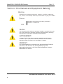
Terms in This Manual and Equipment Marking
Warning
Highlights an operating procedure, practice, condition, statement,
etc., which, if not strictly observed, could result in injury to or death
of
personnel.
Highlights an essential operating procedure,
condition or Statement
NOTE
Caution
The exclamation point within an equilateral triangle is intended to alert the
user to the presence of important operating and maintenance (servicing)
instructions in the literature accompanying the appliance.
AVETISSEMENT!
Le point d´exclamation dans un triangle equilatéral signale à alerter
l´utilisateur qu´il y a des instructions d´operation et d´entretien tres
importantes dans la litérature qui accompagne l´appareil.
VORSICHT
Ein Ausrufungszeichen innerhalb eines gleichwinkeligen Dreiecks
dient dazu, den Benutzer auf wichtige Bedienungs-und
Wartungsanweisungen in der Dem Great beiliegenden Literatur
aufmerksam zu machen.
MatrixPRO-II HD/3G SDI Series –User’s Guide - Rev. 1.1
6
MatrixPRO-II 3G/HD/SD-SDI Routers
Rev. 1.1
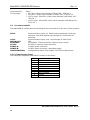
Change History
0.0
1.1
Date
ECP #
Description
Approved By
5/20/10
3/09/11
578607
586286
User’s Guide
Added default IP address
Added interface commands appendix
Added MP-II 3G Configuration Tool
GKOU
GKOU
MatrixPRO-II HD/3G SDI Series –User’s Guide - Rev. 1.1
7
MatrixPRO-II 3G/HD/SD-SDI Routers
Rev. 1.1
Contents
1.1
Product versions ..................................................................................................... 10
2
Specifications................................................................................................ 11
2.1
2.1.1
2.2
2.3
2.4
2.5
2.5.1
Mechanics ................................................................................................................ 11
Weight and power consumption .......................................................................... 11
Power Supply .......................................................................................................... 11
Control...................................................................................................................... 11
Video specifications................................................................................................ 12
Connection details .................................................................................................. 13
Power Supply pinout .............................................................................................. 13
3
Configuration ................................................................................................ 14
3.1
3.2
3.2.1
3.3
3.4
3.5
3.6
SW1 – SW4: Address/Level Not Used ............................................................... 14
SW5-SW6: Router mode....................................................................................... 14
Router mode on NxN square routers .................................................................. 14
SW7: Power alarm ................................................................................................. 18
SW8: Power-up mode............................................................................................ 18
Switching time ........................................................................................................ 19
Configuring protocol options ................................................................................ 19
4
LED status indication .................................................................................. 20
4.1
4.2
4.3
Start-up.................................................................................................................... 20
Alarm states ............................................................................................................ 20
Ethernet states ....................................................................................................... 20
5
Router communication................................................................................ 21
5.1
5.1.1
5.2
Serial connection .................................................................................................... 21
Maximum cable length (RS-232)......................................................................... 21
Ethernet connection ............................................................................................... 22
6
Control Panel operation .............................................................................. 23
6.1
Button description .................................................................................................. 23
7
Environmental Specifications .......................................................................... 25
Appendix A .................................................................................................................. 26
A.1 Materials declaration ...................................................................................................... 26
A.2 Recycling information .................................................................................................... 27
A.3 Declarations of Conformity .................................................................................................. 28
Appendix B Remote Commands.............................................................................. 29
B.1 X-Point Take ....................................................................................................................... 30
MatrixPRO-II HD/3G SDI Series –User’s Guide - Rev. 1.1
8
MatrixPRO-II 3G/HD/SD-SDI Routers
Rev. 1.1
B.2 Request X-Point Status ....................................................................................................... 31
B.3 Router Ping ......................................................................................................................... 32
B.4 Level List............................................................................................................................. 32
Appendix C Barco MPII-3G Configuration Tool .................................................... 33
MatrixPRO-II HD/3G SDI Series –User’s Guide - Rev. 1.1
9
MatrixPRO-II 3G/HD/SD-SDI Routers
Rev. 1.1
Product overview
This User Manual presents the features, installation and operation procedures of (3G/HD/SDSDI) routers of the Barco MatrixPRO-II series.
−
Router models available: 8x8, 16x16 and 32x32
−
Communication: TCP/IP and RS-232
−
Programmable multi- single- and dual bus control panels
−
Ultra Slim frame depth
−
Low Power, high reliability design
−
Redundant power supply system with front indicators
−
Future proof and flexible product range
Barco’s MatrixPRO-II 3G/HS/SD-SDI series is ideal for general events, fixed installations, onair routing, mobile outside broadcast applications and sophisticated A/V applications.
1.1
Product versions
The following versions of the Barco MatrixPRO-II 3G/HD/SD-SDI Routers are available:
1RU, Depth 5cm
R9004661
R9004660
2RU, depth 5cm:
R9004662
8x8 HD/3G Digital Video Router
Multirate: 270Mbps-2.97Gbps
Router partitioning.
Reclocking.
16x16 HD/3G Digital Video Router
Multirate: 270Mbps-2.97Gbps
Router partitioning.
Reclocking.
32x32 HD/3G Digital Video Router
Multirate: 270Mbps-2.97Gbps
Router partitioning.
Reclocking.
MatrixPRO-II HD/3G SDI Series –User’s Guide - Rev. 1.1
10
MatrixPRO-II 3G/HD/SD-SDI Routers
2
2.1
Rev. 1.1
Specifications
Mechanics
Dimensions:
Safety/Emission Standards:
HxWxD = 44x483x50mm, (19”, 1RU);
HxWxD = 88x483x50mm, (19”, 2RU);
Compliant with CE EN55103-1 and 2.
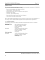
2.1.1 Weight and power consumption
Device
Weight
1.3 kg
1.4 kg
2.2 kg
0.35 kg
R9004661
R9004660
R9004662
R9871081
2.2
Power
14 W
19 W
35 W
Power Supply
SL-PWR-40
AC Supply voltage range:
AC Mains connector:
DC output:
DC connector:
Status monitoring:
Safety standards:
2.3
Current, +15V
Current, -15V
900 mA
2 mA
1273 mA
4 mA
1302 mA
1035 mA
N/A (AC Mains)
40W Power Supply Unit
100-240VAC, 50-60Hz,
Max 1.6A
IEC 320.
+15V, max. 2.2A
-15V, max 1.35A
Maximum 43W
DB9, female.
Via LED in front of the router/CP.
Compliant with CE EN60950, UL-1950/CSA22.2.
Control
Function
Serial Port
NCB
Ethernet port:
Synchronization
Description
RS-232
N/A
10/100BaseT Ethernet bus for external router
control.
o Analog Black & Burst, looped. Both PAL and
NTSC supported.
Tri-Level, Looped. For HD signal formats only.
Connector
1xDB9, female
2x RJ45
1x RJ45
1xBNC
MatrixPRO-II HD/3G SDI Series –User’s Guide - Rev. 1.1
11
MatrixPRO-II 3G/HD/SD-SDI Routers
2.4
Rev. 1.1
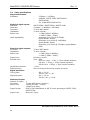
Video specifications
Supported formats:
Broadcast:
-
Electrical signal inputs:
Standard:
Data rate:
Connector:
Impedance:
Return loss:
Cable equalization,
Electrical signal outputs:
Connector:
Impedance:
Return loss:
Signal level:
Rise/fall time:
Amplitude overshoot:
Signal polarity:
Signal transition:
Timing jitter:
Alignment jitter:
270Mbps – 2.97Gbps;
DVB-ASI, SMPTE 259M, SMPTE 292M,
SMPTE 424M;
2K, 2048x1556/23.98 and 24.
SMPTE 259M / SMPTE 292M / SMPTE 424M.
270Mbps – 1.485Gbps / 2.97Gbps.
75 ohm BNC female.
75 ohm nominal.
> 15dB (5MHz-1.485Ghz);
> 10dB (1.5GHz – 3GHz).
Automatic up to 70m @ 2.97Gbps,
typical Belden 1694A;
Automatic up to 100m @ 1.485Gbps,
typical Belden 1694A.
Automatic up to 300m @ 270Mbps, typical Belden
8281.
75 ohm BNC female.
75 ohm nominal.
> 15dB (5MHz-1.485Ghz);
> 10dB (1.5GHz – 3GHz).
800mVp-p ±10%.
20% - 80%
SD limit: 0.4ns – 1.5ns, < 0.5ns rise/fall variation;
HD limit: < 270ps, < 100ps rise/fall variation;
3G-HD limit: < 135ps, < 50ps rise/fall variation;
< 10%.
Non-inverting electrical with respect to inputs.
-
SD: < 0.2 UI
3G-HD / HD: < 1 UI.
SD: < 0.2 UI
3G-HD / HD: < 0.2 UI.
Reference inputs:
Number of inputs: 1
Connector:
75 ohm BNC female, loop-thru.
Return loss:
>40dB (100 kHz – 5 MHz);
>35dB (5-10 MHz).
Signal format:
NTSC or PAL Black&Burst or HD Tri-Level according to SMPTE 274M,
SMPTE 276M.
Signal level:
Nominal 1.0Vp-p.
MatrixPRO-II HD/3G SDI Series –User’s Guide - Rev. 1.1
12
MatrixPRO-II 3G/HD/SD-SDI Routers
Field selectivity:
Timing range:
2.5
Rev. 1.1
Field 1.
• SD, PAL: within clock-intervals (27MHz) 565 – 835 line 6
• SD, NTSC: within clock-intervals (27MHz) 565 – 835 line 10.
• HD Tri-Level: 1280x720: within clock-intervals (148.5MHz) 455 –
780 line 7
• HD Tri-Level: 1920x1080: within clock-intervals (148.5MHz) 625 –
1070 line 7.
Connection details
The MatrixPRO-II routers have the following service connections on the rear of each product:
SYNC:
LOOP:
NCB IN/OUT
ETHERNET:
RS 232:
POWER A:
POWER B:
CONFIGURATION:
Synchronization signal (in). Black burst/composite/tri-level sync
reference input with passive loop-through for vertical interval
switching.
Synchronization signal (out). Loop-through of SYNC input.
N/A.
10/100Base-T Ethernet bus for external router control.
RS-232 for external control protocols.
±15VDC power connector.
±15VDC power connector, redundant supply.
Configurations switch. See Chapter 3 for further descriptions.
2.5.1 Power Supply pinout
The DB9 power pinout for MatrixPRO-II routers is as follows;
Pin #
1
2
3
4
5
6
7
8
9
Description
GND
Not connected
Not connected
+15VDC
Not connected
Not connected
Not connected
-15VDC
Not connected
MatrixPRO-II HD/3G SDI Series –User’s Guide - Rev. 1.1
13
MatrixPRO-II 3G/HD/SD-SDI Routers
3
Rev. 1.1
Configuration
This chapter provides an overview of the configuration options that are available on the
Barco MatrixPRO-II 3G/HD/SD-SDI Routers.
3.1
3.2
SW1 – SW4: Address/Level Not Used
SW5-SW6: Router mode
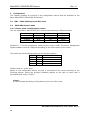
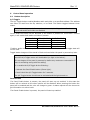
3.2.1 Router mode on NxN square routers
The nxn square Barco MatrixPRO-II A/V router allows switching in different modes:
Router layers
1 layer
2 layers
3 layers
4 layers
8x8 router
8x8
4x4
N.A.
2x2
16x16 router
16x16
8x8
5x5
4x4
32x32 router
32x32
16x16
10x10
8x8
Switches 5 - 6 on the configuration switch set the router’s mode. The Router Management
System software must be configured according to the mode chosen on the router.
The modes can be switched according to the following pattern:
SW 5
OFF
OFF
ON
ON
SW 6
OFF
ON
OFF
ON
1
2
3
4
Router mode
router layer
router layers
router layers
router layers
Default mode is 1 router layer.
Based on the configuration above, the I/O is connected to the router according to the
following scheme, where the physical limitations depend on the type of router that is
purchased (8x8, 16x16, 32x32):
−
1 layer:
I/O is connected according to information on the rear of the router.
MatrixPRO-II HD/3G SDI Series –User’s Guide - Rev. 1.1
14
MatrixPRO-II 3G/HD/SD-SDI Routers
Rev. 1.1
−
2 layers, based on an 8x8 router:
Layer 1
1
2
3
4
Layer 2
1
2
3
4
Output
1
2
3
4
Output
5
6
7
8
−
Layer 1
Input
1
1
2
2
3
3
4
4
Layer 2
Input
1
5
2
6
3
7
4
8
2 layers, based on a 16x16 router:
Layer 1
1
2
3
4
…
8
Layer 2
1
2
3
4
…
8
Output
1
2
3
4
…
8
Output
9
10
11
12
…
16
−
Layer 1
Input
1
1
2
2
3
3
4
4
…
…
8
8
Layer 2
Input
1
9
2
10
3
11
4
12
…
…
8
16
2 layers, based on a 32x32 router:
Layer 1
1
2
3
4
…
16
Layer 2
1
2
3
4
…
16
Output
1
2
3
4
…
16
Output
17
18
19
20
…
32
Layer 1
1
2
3
4
…
16
Layer 2
1
2
3
4
…
16
Input
1
2
3
4
…
16
Input
17
18
19
20
…
32
MatrixPRO-II HD/3G SDI Series –User’s Guide - Rev. 1.1
15
MatrixPRO-II 3G/HD/SD-SDI Routers
−
Rev. 1.1
3 layers, based on a 16x16 router:
Layer 1
1
2
3
4
5
Layer 2
1
2
3
4
5
Layer 3
1
2
3
4
5
Input
1
2
3
4
5
Input
6
7
8
9
10
Input
11
12
13
14
15
Layer 1
1
2
3
4
5
Layer 2
1
2
3
4
5
Layer 3
1
2
3
4
5
Output
1
2
3
4
5
Output
6
7
8
9
10
Output
11
12
13
14
15
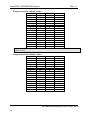
In-/Output 16 is not in use in this router setup (3 router layers, based on a
16x16 router).
−
3 layers, based on a 32x32 router:
Layer 1
1
2
3
…
10
Layer 2
1
2
3
…
10
Layer 3
1
2
3
…
10
Input
1
2
3
…
10
Input
11
12
13
…
20
Input
21
22
23
…
30
Layer 1
1
2
3
…
10
Layer 2
1
2
3
…
10
Layer 3
1
2
3
…
10
Output
1
2
3
…
10
Output
11
12
13
…
20
Output
21
22
23
…
30
MatrixPRO-II HD/3G SDI Series –User’s Guide - Rev. 1.1
16
MatrixPRO-II 3G/HD/SD-SDI Routers
Rev. 1.1
In-/Outputs 31 and 32 are not in use in this router setup (3 router layers, based
on a 32x32 router).
−
4 layers, based on an 8x8 router:
Layer
1
2
Layer
1
2
Layer
1
2
Layer
1
2
1
−
Layer 1
Input
1
1
2
2
Layer 2
Input
1
3
2
4
Layer 3
Input
1
5
2
6
Layer 4
Input
1
7
2
8
4 layers, based on a 16x16 router:
Layer
1
2
3
4
Layer
1
2
3
4
Layer
1
2
3
4
Layer
1
2
3
4
1
−
Layer 1
Input
1
1
2
2
3
3
4
4
Layer 2
Input
1
5
2
6
3
7
4
8
Layer 3
Input
1
9
2
10
3
11
4
12
Layer 4
Input
1
13
2
14
3
15
4
16
4 layers, based on a 32x32 router:
Layer 1
1
2
…
8
Input
1
2
…
8
2
3
4
2
3
4
Layer 1
1
2
…
8
Output
1
2
Output
3
4
Output
5
6
Output
7
8
Output
1
2
3
4
Output
5
6
7
8
Output
9
10
11
12
Output
13
14
15
16
Output
1
2
…
8
MatrixPRO-II HD/3G SDI Series –User’s Guide - Rev. 1.1
17
MatrixPRO-II 3G/HD/SD-SDI Routers
Layer 2
1
2
…
8
Layer 3
1
2
…
8
Layer 4
1
2
…
8
3.3
Rev. 1.1
Input
9
10
…
16
Input
17
18
…
24
Input
25
26
…
32
Layer 2
1
2
…
8
Layer 3
1
2
…
8
Layer 4
1
2
…
8
Output
9
10
…
16
Output
17
18
…
24
Output
25
26
…
32
SW7: Power alarm
The power alarm can be switched according to the following pattern:
SW 7
OFF
ON
Power alarm
Disables Power Alarm
Enables Power Alarm
Default setting is Power Alarm disabled.
Changing this from default setting should only be done when using two
(redundant) power supplies.
3.4
SW8: Power-up mode
Switch 8 on the configuration switch defines the power up mode on NxN square routers. The
MatrixPRO-II router provides two modes for powering up the system.
The power up options can be switched according to the following pattern:
SW 8
OFF
ON
Power Up mode
Switches all outputs according to the buffered information in the
routers processor system.
Switches all outputs to input 1.
Default setting switches all outputs according to the buffered information in the routers
processor system.
MatrixPRO-II HD/3G SDI Series –User’s Guide - Rev. 1.1
18
MatrixPRO-II 3G/HD/SD-SDI Routers
3.5
Rev. 1.1
Switching time
Switching is performed according to the detected sync reference signal. Switching time is
determined by the synchronization signal that feeds the router. This is useful when the video
signal has the same format as the synchronization signal. Supported formats are: PAL,
NTSC, 750/50p, 750/60p, 1125/50i and 1125/60i.
3.6
Configuring protocol options
TCP/IP
This is the default option for the Barco MatrixPRO-II HD/3G SDI routers. Selecting this
protocol disables the RS-232 port of that device.
RS232
The serial protocol can be selected from the configurator software. Selecting the RS232
protocol disables the Ethernet port of that device.
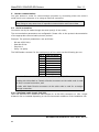
Default IP Address: 192.168.0.245 - Port: 4381
RS-232 parameters:
- Bit rate: 19200 bit/s
- Data bits: 8
- Stop bits: 1
- Parity: no parity
Connection to the router will be lost after 20 seconds of inactivity
MatrixPRO-II HD/3G SDI Series –User’s Guide - Rev. 1.1
19
MatrixPRO-II 3G/HD/SD-SDI Routers
4
4.1
Rev. 1.1
LED status indication
Start-up
The LED located at the front of the router indicates the status of the router. At start-up, the
LED will alternate between red (R) and green (G) every 500ms for about two seconds. After
the start-up sequence the LED will indicate the Alarm state of the router.
There are two LEDs located at the Ethernet bus. At start-up the boot loader is searching for
update commands on the serial port for about two seconds. During this sequence both
Ethernet LEDs will be blinking. After the start-up sequence the LEDs will indicate the
Ethernet state.
4.2
Alarm states
The LED can either be red (R), green (G), yellow (Y) or have no light (N).
The LED state is here described with twenty letters, each representing 100ms, which totals
to an alarm sequence of two seconds. The X indicates that the LED keeps the color it has the
moment the alarm sequence begins (green, yellow or no light).
Description
Continuous
green light
Continuous
yellow light
LED state
GGGGG GGGGG GGGGG GGGGG
Long red
blinks
One short
red blink
RRRRR NNNNN RRRRR NNNNN
Alarm
No alarm. Status
is OK.
Unable to
connect to
controller over
Ethernet.
Power is too low.
RXXXX XXXXX XXXXX XXXXX
Power A failed
Two short
red blinks
XXXXX XXXXX RXRXX XXXXX
Power B failed
4.3
YYYYY YYYYY YYYYY YYYYY
Comment
This alarm will be
overwritten by
other alarms
Only active if
power alarm dip is
set.
Only active if
power alarm dip is
set.
Ethernet states
The LEDs that are located at the Ethernet bus will after the Start-up sequence indicate the
Ethernet states:
Green
Yellow
On
Valid link
No data
Off / Blinking
No link
Data is transmitted or
received
MatrixPRO-II HD/3G SDI Series –User’s Guide - Rev. 1.1
20
MatrixPRO-II 3G/HD/SD-SDI Routers
5
Rev. 1.1
Router communication
You gain access to router for communication purposes by connecting either the router’s
serial port to your computer or by using an Ethernet connection.
Do not use both the router’s Ethernet port and RS-232 serial port at the same
time. Doing so may cause loss of important communication and control data.
5.1
Serial connection
Connection can by be made through the serial port(s) of the router;
The communication parameters are configurable. Please refer to the protocol documentation
of the appropriate communication/control protocol.
Example: The protocol parameters s are as follows:
−
Bit rate 19200 bit/s
−
Data bits 8 bits
−
Stop bits 1
−
Parity: No parity
The DB9 female connector for the serial port(s) of the router has the following pin-out:
Pin #
1
2
3
4
5
6
7
8
9
RS-232 mode
Not in use
Tx
Rx
Not in use
GND
GND
RTS
CTS
Do Not Connect!
Note that if the standard RS-232 cable specification (DCE) is followed:
A cable with Male+Male or Female+Female connectors at the cable ends is used
for Rx/Tx crossed connection, and
A cable with Male+Female connectors at the cable ends is used for a straight
through connection.
5.1.1 Maximum cable length (RS-232)
IEEE has specified the maximum cable length for an RS-232 connection to 15m. Longer
distances can be installed depending on the environmental conditions of the installation site.
MatrixPRO-II HD/3G SDI Series –User’s Guide - Rev. 1.1
21
MatrixPRO-II 3G/HD/SD-SDI Routers
5.2
Rev. 1.1
Ethernet connection
The connections follow the standard set by the IEEE 802.3 100BaseTX specification. The
cables that are to be applied should be CAT-5 / CAT-5E standard, or better. It is the
responsibility of the installer / user to secure a proper installation of the Ethernet
connection.
All Barco MatrixPRO-II routers and IP-based Control Panels are connected together through
an Ethernet Switch.
A Barco MatrixPRO-II device has only one physical Ethernet connection. If redundant control
is required, this limitation has to be solved by the control system.
The default IP address is: 192.168.0.245 port: 4381
Connection to the router will be lost after 20 seconds of inactivity
MatrixPRO-II HD/3G SDI Series –User’s Guide - Rev. 1.1
22
MatrixPRO-II 3G/HD/SD-SDI Routers
6
6.1
Rev. 1.1
Control Panel operation
Button description
A/V Toggle
The A/V Toggle button enables/disables audio and video on a specified address. The address
can either be read from the dip switches, or be fixed. The button toggles between three
states.
If the button is pressed for more than 1 second, it will go into a fourth state
where both audio and video are disabled.
In this state the button will be dimmed. If the button is pressed for more than 1 second
again, it will enable both audio and video if present.
Button Color Video Enabled Audio Enabled
Yellow
Yes
Yes
Green
Yes
No
Red
No
Yes
Dimmed
No
No
If neither audio nor video is present, it will be marked as disabled and the toggle state will
not be used.
Toggle status changes will be stored in flash and used when the panel is powered up later.
When a panel is powered on it will search for connected routers. If no routers are
found the A/V Toggle button will be disabled (no light in the button).
This can happen if the panel is powered up before any routers are connected or if
there is something wrong with the cabling.
To re-enable the A/V Toggle do the following:
1. Activate the Panel Enable button (Green light).
2. Push & Hold the A/V Toggle-button for 2 seconds.
The A/V Toggle-button should now be activated and the light turned on.
Panel Enable
If a Panel Enable button is present, the panel will start up not enabled. In this state the
button will be red and all the other buttons will be disabled. When pressing the button the
panel will be enabled and the color will change to green. A status request will also be sent to
get information on active levels.
If no Panel Enable button is present, the panel will start up enabled.
MatrixPRO-II HD/3G SDI Series –User’s Guide - Rev. 1.1
23
MatrixPRO-II 3G/HD/SD-SDI Routers
Rev. 1.1
Take on/off
The Take on/off button enables or disables the Take button. If no take button is defined,
Take on/off is always off. On first start-up the take button is enabled. Later it will read the
last status from the flash memory.
Take
The Take buttons LED is normally off. If the Take on/off button is set to “on”, no commands
will be sent from the panel until the Take button is pressed. The last selected buttons and
the take button will blink, until the Take button is pressed and the command is sent from the
panel.
Output
An Output button is used for selecting an output. Selecting an output activates it, so that it
is switched to the next input that is selected.
Input
An Input button switches the active output to the selected input. If the Take button is
enabled, the switch will not be executed until the Take button is pressed.
When switching using the Input button, all enabled audio- and video-levels will be switched
from the selected input to the active output.
MatrixPRO-II HD/3G SDI Series –User’s Guide - Rev. 1.1
24
MatrixPRO-II 3G/HD/SD-SDI Routers
Rev. 1.1
7
Environmental Specifications
1.
The equipment will meet the guaranteed performance specification under the
following environmental conditions:
Operating room temperature
0°C to 45°C
range:
Operating relative humidity range: <95% (non-condensing)
2.
-
The equipment will operate without damage under the following environmental
conditions:
Temperature range:
-10°C to 55°C
Relative humidity range:
<95% (non-condensing)
MatrixPRO-II HD/3G SDI Series –User’s Guide - Rev. 1.1
25
MatrixPRO-II 3G/HD/SD-SDI Routers
Rev. 1.1
Appendix A
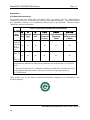
A.1 Materials declaration
For product sold into China after 1st March 2007, we comply with the “Administrative
Measure on the Control of Pollution by Electronic Information Products”. In the first stage of
this legislation, content of six hazardous materials has to be declared. The table below
shows the required information.
Toxic or hazardous substances and elements
組成名稱 鉛
汞
镉
六价铬
多溴二苯醚
多溴联苯
Part Lead Mercury Cadmium Hexavalent Polybrominated Polybrominated
Name (Pb) (Hg)
(Cd)
Chromium
biphenyls
diphenyl ethers
(PBB)
(Cr(VI))
(PBDE)
All
products
referred
to in
Chapter
1.1
SLPWR-40
/
SLPWR-90
O
O
O
O
O
O
O
O
O
O
O
O
O: Indicates that this toxic or hazardous substance contained in all of the
homogeneous materials for this part is below the limit requirement in SJ/T113632006.
X: Indicates that this toxic or hazardous substance contained in at least one of the
homogeneous materials used for this part is above the limit requirement in
SJ/T11363-2006.
Parts without any of the above mentioned hazardous substances are indicated by the
product marking:
MatrixPRO-II HD/3G SDI Series –User’s Guide - Rev. 1.1
26
MatrixPRO-II 3G/HD/SD-SDI Routers
Rev. 1.1
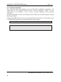
A.2 Recycling information
Please contact Barco’s Customer Support for assistance with recycling if this site does not
show the information you require.
Where it is not possible to return the product to Barco or its agents for recycling, the
following general information may be of assistance:
−
Before attempting disassembly, ensure the product is completely disconnected from
power and signal connections.
−
All major parts are marked or labeled to show their material content.
−
Depending on the date of manufacture, this product may contain lead in solder.
−
Some circuit boards may contain battery-backed memory devices.
MatrixPRO-II HD/3G SDI Series –User’s Guide - Rev. 1.1
27
MatrixPRO-II 3G/HD/SD-SDI Routers
Rev. 1.1
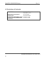
A.3 Declarations of Conformity
DESCRIPTION
3G/HD/SD-SDI Video Routers in the Barco
MatrixPRO-II series
DIRECTIVES this equipment
complies with
LVD 73/23/EEC
EMC 2004/108/EEC
HARMONISED STANDARDS applied
in order to verify compliance with
Directive(s)
EN 55103-1:1996
EN 55103-2:1996
MatrixPRO-II HD/3G SDI Series –User’s Guide - Rev. 1.1
28
MatrixPRO-II 3G/HD/SD-SDI Routers
Rev. 1.1
Appendix B Remote Commands
Description
x
X-point Take.
ls
Status X-point – level.
ping
Router ping.
llist
Level list
Default Address: 192.168.0.245 port: 4381
Connection to the router will be lost after 20 seconds
MatrixPRO-II HD/3G SDI Series –User’s Guide - Rev. 1.1
29
MatrixPRO-II 3G/HD/SD-SDI Routers
Rev. 1.1
B.1 X-Point Take
This command directly takes the specified X-point. The command specifies which sources to
connect to which destinations and on what levels. Several X-point takes can be specified on
a single command line. In such cases all specified X-points are taken simultaneously.
Command:
x <X-points>[ : <group_no>][*CC]<LF>
<LF>
Response:
%<LF>
x l<level> <src> <dest><LF>
[*CC<LF>]
<LF>
Where:
<X-points>=<X-point>[ <X-points>]
<X-point>=l<levels> <src_dest_pairs>
<src_dest_pairs>=<src_dest_pair>[ <src_dest_pairs>]
<src_dest_pair>=<src> <dests>
<levels>={<level>|<levels>,<levels>|<level>-<level>}
<dests>={<dest>|<dests>,<dests>|<dest>-<dest>}
<level>
<src>
<dest>
The level number.
Source number in the range from zero to one less than the number of inputs
on the level. <src> can also be one of the following characters:
d
Disconnect. Used when a destination is not connected to any source.
o
Out of range. Used when a destination is connected to a source not
included in a level. This may occur with overlapping partitions. Only
valid in the response.
u
Undefined/Unknown. This might be used at start-up before the status
is read from the physical router. It is also used on ported routers
where a port can be used as an input or an output. Only valid in the
response.
Destination number in the range from zero to one less than the number of
outputs on the level.
MatrixPRO-II HD/3G SDI Series –User’s Guide - Rev. 1.1
30
MatrixPRO-II 3G/HD/SD-SDI Routers
Rev. 1.1
A single X-point Take command can switch multiple X-points. You will however receive one
response for each X-point that is switched.
Example:
Command
X l1 1 12
Echo
X l1 1 12
Desired action
Switch input 1 to output 12 in level 1
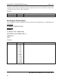
B.2 Request X-Point Status
This command is used to requests the X-point status of all destinations on a specified level.
Command:
s l<level1> [*CC]<LF><LF>
Response:
%<LF>
x l<level> <src> <dest><LF>
[x l<level> <src> <dest><LF> …]
[*CC<LF>]
<LF>
Example:
Command
s l1
Echo
X l1 15
X l1 15
X l1 15
X l1 15
X l1 15
X l1 15
X l1 15
X l1 15
X l1 15
X l1 15
X l1 15
X l1 15
X l1 15
X l1 15
X l1 15
X l1 15
Desired action
0
1
2
3
4
5
6
7
8
9
10
11
12
13
14
15
Report x-point status in level 1
MatrixPRO-II HD/3G SDI Series –User’s Guide - Rev. 1.1
31
MatrixPRO-II 3G/HD/SD-SDI Routers
Rev. 1.1
B.3 Router Ping
This command is used to check if the router is still responding.
Command:
ping[*CC]<LF><LF>
Response:
? "ping"<LF>
pong<LF>
[*CC<LF>]
<LF>
Example:
Command
ping
Echo
pong
Desired action
B.4 Level List
This command is used to the get list of all levels in the system.
Command:
llist <LF><LF>
Response:
? "llist" <LF>
l<level> <size> <format> "<description>"<LF>
[l<level> …]
[*CC<LF>]
<LF>
Example:
Command
llist
Echo
L1 16x16 Video-3GHD-SDI “Video Level”
Desired action
Provide the list in level 1
MatrixPRO-II HD/3G SDI Series –User’s Guide - Rev. 1.1
32
MatrixPRO-II 3G/HD/SD-SDI Routers
Rev. 1.1
Appendix C Barco MPII-3G Configuration Tool
The Barco MPII-3G Tool is a software utility that allows the user to:
•
Read the IP settings
•
Modify and Save IP settings
•
Switching the communication between Ethernet and the serial RS-232 protocols
MatrixPRO-II HD/3G SDI Series –User’s Guide - Rev. 1.1
33