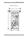
1
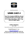
®
Serial/Communications
USBS 2401-I
One-Port Isolated USB-Bus Serial
Communication Converter with
921.6 kbps Data Rate, ASIC Chip
and 6-ft USB Cable
USER’S MANUAL
VER. C • 2002
No part of this manual may be reproduced without permission
CyberResearch , Inc.
®
www.cyberresearch.com
25 Business Park Dr., Branford, CT 06405 USA
203-483-8815 (9am to 5pm EST) FAX: 203-483-9024
®
CyberResearch Communication Converters
USBS 2401-I
©Copyright 2001
All Rights Reserved.
2002
The information in this document is subject to change without prior notice
in order to improve reliability, design, and function and does not represent
a commitment on the part of CyberResearch, Inc.
In no event will CyberResearch, Inc. be liable for direct, indirect, special,
incidental, or consequential damages arising out of the use of or inability
to use the product or documentation, even if advised of the possibility of
such damages.
This document contains proprietary information protected by copyright.
All rights are reserved. No part of this manual may be reproduced by any
mechanical, electronic, or other means in any form without prior written
permission of CyberResearch, Inc.
Trademarks
“CyberResearch,” and “USBS 2401-I,” are trademarks of CyberResearch,
Inc. Other product names mentioned herein are used for identification
purposes only and may be trademarks and/or registered trademarks of
their respective companies.
• NOTICE •
CyberResearch, Inc. does not authorize any CyberResearch product for
use in life support systems, medical equipment, and/or medical devices
without the written approval of the President of CyberResearch, Inc. Life
support devices and systems are devices or systems which are intended
for surgical implantation into the body, or to support or sustain life and
whose failure to perform can be reasonably expected to result in injury.
Other medical equipment includes devices used for monitoring, data
acquisition, modification, or notification purposes in relation to life
support, life sustaining, or vital statistic recording. CyberResearch
products are not designed with the components required, are not subject
to the testing required, and are not submitted to the certification required
to ensure a level of reliability appropriate for the treatment and diagnosis of
humans.
CyberResearch, Inc.
25 Business Park Drive
Branford, CT USA
iii
P: (203) 483-8815; F: (203) 483-9024
www.cyberresearch.com
USBS 2401-I
®
CyberResearch Communication Converters
Intentionally Blank
iv
USBS 2401-I
®
CyberResearch Communication Converters
USBS 2401-I
Contents
INTRODUCTION ........................................................................ 1
OVERVIEW......................................................................................1
WHAT’S INCLUDED ........................................................................1
INSTALLATION ......................................................................... 2
OPERATING SYSTEM INSTALLATION ...............................................2
SYSTEM INSTALLATION ..................................................................2
CONFIGURATION ..................................................................... 6
ELECTRICAL INTERFACE SELECTION ..............................................6
SWITCH EXAMPLES.........................................................................7
TECHNICAL DESCRIPTION....................................................... 8
FEATURES .......................................................................................8
CONNECTOR PIN ASSIGNMENTS (DB25 MALE)..............................8
SPECIFICATIONS ...................................................................... 9
ENVIRONMENTAL SPECIFICATIONS .................................................9
MANUFACTURING...........................................................................9
POWER CONSUMPTION ...................................................................9
MEAN TIME BETWEEN FAILURES (MTBF) .....................................9
PHYSICAL DIMENSIONS ..................................................................9
APPENDIX A - TROUBLESHOOTING ...................................... 10
APPENDIX B - ELECTRICAL INTERFACE .............................. 11
RS-422.........................................................................................11
RS-485.........................................................................................11
APPENDIX C - GROUND LOOP PHENOMENON ...................... 12
WHAT IS GROUND LOOP? .............................................................12
CABLING RECOMMENDATIONS .....................................................12
APPENDIX D - ASYNCHRONOUS COMMUNICATIONS ............ 13
APPENDIX E - SILK-SCREEN ................................................. 14
APPENDIX F - SILK-SCREEN ................................................. 15
CyberResearch, Inc.
25 Business Park Drive
Branford, CT USA
v
P: (203) 483-8815; F: (203) 483-9024
www.cyberresearch.com
®
CyberResearch Communication Converters
USBS 2401-I
APPENDIX G - COMPLIANCE NOTICES ................................. 16
FEDERAL COMMUNICATIONS COMMISSION STATEMENT ..............16
EMC DIRECTIVE STATEMENT ......................................................16
WARRANTY ............................................................................ 17
Figures
Figure 1- RS-422, 4 Wire RS-485 (Default) .............................................7
Figure 2 - RS-485, 2 Wire with Echo........................................................7
Figure 3 - RS-485, 2 Wire No Echo ..........................................................7
Figure 4 – USBS 2401-I cabling example...............................................13
Figure 5 - Asynchronous Communications Bit Diagram .....................14
vi
USBS 2401-I
®
CyberResearch Communication Converters
USBS 2401-I
Introduction
Overview
The CyberResearch USBS 2401-I equips the PC with 1 isolated USB to
RS-422/485 Asynchronous serial port providing a versatile interface for
common RS-422/485 needs. The USBS 2401-I connects through the PC’s
external USB port, so it does not require opening the computer case. Resources
such as IRQ’s and I/O addresses are also not utilized. It does require a system
that supports USB in hardware and operating system.
What’s Included
The USBS 2401-I is shipped with the following items. If any of these items is
missing or damaged, contact the supplier.
x
x
x
USBS 2401-I Isolated USB to RS-422/485 Serial I/O Adapter
USB Cable Part Number CA179 for Connecting to Upstream
Host/Hub
Sealevel Software
CyberResearch, Inc.
25 Business Park Drive
Branford, CT USA
1
P: (203) 483-8815; F: (203) 483-9024
www.cyberresearch.com
®
CyberResearch Communication Converters
USBS 2401-I
Installation
Operating System Installation
Please note that you should install the software before the hardware.
Choose Install Software at the beginning of the CD and select the Serial I/O
software drivers and install SeaCOM.
System Installation
The screen captures below are taken from a Windows 98 installation. Your
particular operating system may differ slightly from what is shown based on
your version of windows.
The USBS 2401-I can be connected to any Upstream Type “A” port either at
the PC host or an Upstream Hub. The USBS 2401-I is hot-pluggable,
meaning there is no need to power down your computer prior to installation.
The USBS 2401-I has an onboard 8 position dip switch that is used to
configure the interface. Prior to connecting the USBS 2401-I be sure to
configure this dip switch for your specific application. Please see the
Configuration section for more information. The USBS 2401-I is defaulted to
RS-422 mode so changes are only required if you will be using the product in an
RS-485 application.
1.
After installing the software connect USBS 2401-I to an Upstream Host
or Hub.
A "New Hardware Found," dialog box will appear. This indicates that the system has
recognized the new device and will now proceed to locate a driver.
2
USBS 2401-I
®
CyberResearch Communication Converters
USBS 2401-I
Since you have already installed the software by running “Setup”, simply click
“Next” to proceed. The drivers that were installed during setup will
automatically be used to configure the adapter for use.
CyberResearch, Inc.
25 Business Park Drive
Branford, CT USA
3
P: (203) 483-8815; F: (203) 483-9024
www.cyberresearch.com
USBS 2401-I
®
CyberResearch Communication Converters
USBS 2401-I to RS-422/485 Serial Converter
Windows has now located a driver and installed the software. After the driver
has been located click “Finish. You should see one more “New Hardware
Found”, indicating the actual port being created. If you view your systems
Device Manager at this point, you should have a new “COM” port in the
Port(COM & LPT) Device Class. It should look similar to the screen shot on the
following page.
4
USBS 2401-I
®
CyberResearch Communication Converters
USBS 2401-I
CyberResearch Serial Converter (COM 5)
You can access your new COM: port by using the assigned COM: identifier
shown above. In this case, it is COM5: but this assignment will vary from
system to system. At this point, the hardware is recognized. To verify operation
use CyberResearch supplied WinSSD diagnostic utility. WinSSD can be
found in the Start menu under Programs, SeaCOM group.
CyberResearch, Inc.
25 Business Park Drive
Branford, CT USA
5
P: (203) 483-8815; F: (203) 483-9024
www.cyberresearch.com
®
CyberResearch Communication Converters
USBS 2401-I
Configuration
Electrical Interface Selection
The port on the USBS 2401-I has the ability to be used in both half and full
duplex RS-422/485 applications. This is selectable through DIP-switch SW1.
The chart below describes each of the switch position’s function. Please refer to
the following page for switch setting examples. Switch SW1, in the “ON”
position, either enables, adds or connects, based on the function of the switch
position listed below. Switch SW1, position OFF, disables, removes or
disconnects .
6
SW1
Function
1
RS-485 Two Wire Auto Enable/Disable
2
Echo Enable/Disable
3
Adds or removes the 120 ohm termination
4
Adds or removes the 1K ohm pull-up resistor in the
RS-422/RS-485 receiver circuit (Receive data only)
5
Adds or removes the 1K ohm pull-down resistor in the
RS-422/RS-485 receiver circuit (Receive data only)
6
Connects the TX+ to RX+ for RS-485 two wire operation
7
Connects the TX- to RX- for RS-485 two wire operation
8
Not Used
USBS 2401-I
®
CyberResearch Communication Converters
USBS 2401-I
Switch Examples
Please use the following examples to configure your adapter.
ON
R S -42 2
O FF
1 2 3 4 5 6 7 8
Figure 1- RS-422, 4 Wire RS-485 (Default)
ON
R OSFF-4 85
O FF
1 2 3 4 5 6 7 8
Figure 2 - RS-485, 2 Wire with Echo
ON
R S -48 5
O FF
1 2 3 4 5 6 7 8
Figure 3 - RS-485, 2 Wire No Echo
CyberResearch, Inc.
25 Business Park Drive
Branford, CT USA
7
P: (203) 483-8815; F: (203) 483-9024
www.cyberresearch.com
®
CyberResearch Communication Converters
USBS 2401-I
Technical Description
The USBS 2401-I: utilizes a USB UART. This chip features programmable
baud rate, data format, 128 byte Dual Port TX Buffer, and 384 byte Dual Port
RX Buffer. The RS-422/485 transceiver supports data rates up to 921.6K baud.
Features
x
Hot-Pluggable device
x
Does not require opening the case
x
No system resources are required (i.e. I/O ports or IRQ’s)
x
LED status indicators for “USB Enabled”, “TD”, and “RD”
Connector Pin Assignments (DB25 Male)
The USBS 2401-I complies with the EIA-530 pin out with the following
signals supported
Signal
GND
RDB
RDA
TDB
TDA
RX+
RXTX+
TX-
Name
Ground
Receive Positive
Receive Negative
Transmit Positive
Transmit Negative
Pin #
7
16
3
14
2
Mode
Input
Input
Output
Output
Technical Note: The modem control signals are biased as follows : RTS is
connected to CTS, DTR is connected to DCD and DSR, and RI is tied
inactive.
8
USBS 2401-I
®
CyberResearch Communication Converters
USBS 2401-I
Specifications
Environmental Specifications
Specification
Temperature
Range
Humidity Range
Operating
0º to 50º C
(32º to 122º F)
10 to 90% R.H.
Non-Condensing
Storage
-20º to 70º C
(-4º to 158º F)
10 to 90% R.H.
Non-Condensing
Manufacturing
x
All CyberResearch Printed Circuit boards are built to UL 94V0 rating and
are 100% electrically tested. These printed circuit boards are solder mask
over bare copper or solder mask over tin nickel.
Power Consumption
Supply line
Rating
+5 VDC
100 mA
Mean Time Between Failures (MTBF)
Greater than 150,000 hours. (Calculated)
Physical Dimensions
Package Length
Package Width
Package Height
CyberResearch, Inc.
25 Business Park Drive
Branford, CT USA
3.8 inches
2.3 inches
1.0 inches
(9.66 cm)
(5.84 cm)
(2.54 cm)
9
P: (203) 483-8815; F: (203) 483-9024
www.cyberresearch.com
USBS 2401-I
®
CyberResearch Communication Converters
Appendix A - Troubleshooting
Serial Utility test software is supplied with the CyberResearch adapter and
should be used in the troubleshooting procedures. Using this software and
following these steps, most common problems can be eliminated.
10
1.
If your adapter isn’t working, first check to make sure that USB support is
enabled in the System BIOS and it is functioning properly in the operating
system. This can be done by using either the Windows 98/ME or Windows
2000 Device Manager.
2.
Ensure that the CyberResearch software has been installed on the
machine so that the necessary files are in place to complete the installation.
3.
When the USBS 2401-I is configured properly, the USB Enabled LED
(EN) will be lit. This should allow you to use Sealevel’s WinSSD utility
and the supplied loopback plug to check communications. The supplied
loopback plug connects TD to RD. If you decide to test the Modem
Control Signals, a full pin loopback plug will be required. Details on
loopback plugs are included on WinSSD. Contact CyberResearch if you
need further assistance
4.
When testing the USBS 2401-I in loopback mode, you should see both
the TD and RD LED”s flashing as well as seeing echoed data on the screen.
The loopback test first transmits a HEX pattern, 55AA, and then an ASCII
string of data. If this test passes, then the USBS 2401-I is ready for use in
your application.
5.
Please note that if the card is configured for 2 wire RS-485 with no echo a
loopback test is not possible. The receiver in this case will be turned off and
the test will fail. If you plan on using this device in two wire mode test the
adapter in RS-422 mode first. Then configure the adapter for your
application.
USBS 2401-I
®
CyberResearch Communication Converters
USBS 2401-I
Appendix B - Electrical Interface
RS-422
The RS-422 specification defines the electrical characteristics of balanced
voltage digital interface circuits. RS-422 is a differential interface that defines
voltage levels and driver/receiver electrical specifications. On a differential
interface, logic levels are defined by the difference in voltage between a pair of
outputs or inputs. In contrast, a single ended interface, for example RS-232,
defines the logic levels as the difference in voltage between a single signal and a
common ground connection. Differential interfaces are typically more immune
to noise or voltage spikes that may occur on the communication lines.
Differential interfaces also have greater drive capabilities that allow for longer
cable lengths. RS-422 is rated up to 10 Megabits per second and can have
cabling 4000 feet long. RS-422 also defines driver and receiver electrical
characteristics that will allow 1 driver and up to 32 receivers on the line at once.
RS-422 signal levels range from 0 to +5 volts. RS-422 does not define a
physical connector.
RS-485
RS-485 is backwardly compatible with RS-422; however, it is optimized for
partyline or multi-drop applications. The output of the RS-422/485 driver is
capable of being Active (enabled) or Tri-State (disabled). This capability
allows multiple ports to be connected in a multi-drop bus and selectively polled.
RS-485 allows cable lengths up to 4000 feet and data rates up to 10 Megabits
per second. The signal levels for RS-485 are the same as those defined by
RS-422. RS-485 has electrical characteristics that allow for 32 drivers and 32
receivers to be connected to one line. This interface is ideal for multi-drop or
network environments. RS-485 tri-state driver (not dual-state) will allow the
electrical presence of the driver to be removed from the line. Only one driver
may be active at a time and the other driver(s) must be tri-stated. RS-485 can be
cabled in two ways, two wire and four wire mode. Two wire mode does not
allow for full duplex communication and requires that data be transferred in
only one direction at a time. For half-duplex operation, the two transmit pins
should be connected to the two receive pins (Tx+ to Rx+ and Tx- to Rx-). Four
wire mode allows full duplex data transfers. RS-485 does not define a connector
pin-out or a set of modem control signals. RS-485 does not define a physical
connector.
CyberResearch, Inc.
25 Business Park Drive
Branford, CT USA
11
P: (203) 483-8815; F: (203) 483-9024
www.cyberresearch.com
®
CyberResearch Communication Converters
USBS 2401-I
Appendix C - Ground Loop Phenomenon
What is Ground Loop?
Ground loop Phenomenon occurs when two (or more) pieces of equipment are
connected together with a common ground and a different ground potential
exists at each location. This current can cause the connected equipment to
experience noise that in turn causes data transmission errors. In extreme cases
ground current can cause equipment malfunction or even destruction.
Cabling Recommendations
When connecting the USBS 2401-I in an RS-485 network, care should be
taken that both ends of the network are not isolated from ground (see Figure 4).
This “floating” ground condition could cause capacitive or inductive coupling of
voltages that will cause a break down in the DC to DC converter circuit or in the
opto-isolator circuit. This condition will cause data errors and possibly
destruction of the receiver circuit.
A
Isolated
Adapter
Isolation
Barrier
B
DATA+
DATAGround
Non
Isolated
Adapter
Figure 4 – USBS 2401-I cabling example
12
USBS 2401-I
®
CyberResearch Communication Converters
USBS 2401-I
Appendix D - Asynchronous Communications
Serial data communications implies that individual bits of a character are
transmitted consecutively to a receiver that assembles the bits back into a
character. Data rate, error checking, handshaking, and character framing
(start/stop bits) are pre-defined and must correspond at both the transmitting and
receiving ends.
Asynchronous communications is the standard means of serial data
communication for PC compatibles and PS/2 computers. The original PC was
equipped with a communication or COM: port that was designed around an
8250 Universal Asynchronous Receiver Transmitter (UART). This device
allows asynchronous serial data to be transferred through a simple and
straightforward programming interface. Character boundaries for asynchronous
communications are defined by a starting bit followed by a pre-defined number
of data bits (5, 6, 7, or 8). The end of the character is defined by the
transmission of a pre-defined number of stop bits (usually 1, 1.5 or 2). An extra
bit used for error detection is often appended before the stop bits.
fÇäÉ=ëí~íÉ=çÑ
======äáåÉ
N
R=íç=U=a~í~=_áíë
lÇÇI=bîÉå=
======çê
==råìëÉÇ
=m
_fq
M
oÉã~áå=fÇäÉ=çê
åÉñí=ëí~êí=Äáí
pqlm
N
NKR
O
Figure 5 - Asynchronous Communications Bit Diagram
This special bit is called the parity bit. Parity is a simple method of determining
if a data bit has been lost or corrupted during transmission. There are several
methods for implementing a parity check to guard against data corruption.
Common methods are called (E)ven Parity or (O)dd Parity. Sometimes parity is
not used to detect errors on the data stream. This is refereed to as (N)o parity.
Because each bit in asynchronous communications is sent consecutively, it is
easy to generalize asynchronous communications by stating that each character
is wrapped (framed) by pre-defined bits to mark the beginning and end of the
serial transmission of the character. The data rate and communication
parameters for asynchronous communications have to be the same at both the
transmitting and receiving ends. The communication parameters are baud rate,
parity, number of data bits per character, and stop bits (i.e. 9600,N,8,1).
CyberResearch, Inc.
25 Business Park Drive
Branford, CT USA
13
P: (203) 483-8815; F: (203) 483-9024
www.cyberresearch.com
®
CyberResearch Communication Converters
USBS 2401-I
Appendix E - Silk-Screen
3.28 in
2.09 in
1.39 in
14
USBS 2401-I
®
CyberResearch Communication Converters
USBS 2401-I
Appendix F - Compliance Notices
Federal Communications Commission Statement
FCC - This equipment has been tested and found to comply with the limits for
Class A digital device, pursuant to Part 15 of the FCC Rules. These limits are
designed to provide reasonable protection against harmful interference when the
equipment is operated in a commercial environment. This equipment generates,
uses, and can radiate radio frequency energy and, if not installed and used in
accordance with the instruction manual, may cause harmful interference to radio
communications. Operation of this equipment in a residential area is likely to
cause harmful interference. In such case the user will be required to correct the
interference at his own expense.
EMC Directive Statement
Products bearing the CE Label fulfill the requirements of
the EMC directive (89/336/EEC) and of the low-voltage
directive (73/23/EEC) issued by the European
Commission.
To obey these directives, the following European standards must be met:
EN55022 Class B - ‘Limits and methods of measurement of radio
interference characteristics of information technology equipment’
EN55024-‘Information
technology
equipment
characteristics Limits and methods of measurement.
Immunity
EN60950 (IEC950) - ‘Safety of information
equipment, including electrical business equipment’
technology
Always use cabling provided with this product if possible. If no cable is
provided or if an alternate cable is required, use high quality shielded cabling to
maintain compliance with EMC directives.
CyberResearch, Inc.
25 Business Park Drive
Branford, CT USA
15
P: (203) 483-8815; F: (203) 483-9024
www.cyberresearch.com
USBS 2401-I
®
CyberResearch Communication Converters
Intentionally Blank
18
USBS 2401-I
®
CyberResearch Communication Converters
USBS 2401-I
Product Service
Diagnosis and Debug
CyberResearch, Inc. maintains technical support lines staffed by experienced
Applications Engineers and Technicians. There is no charge to call and we will
return your call promptly if it is received while our lines are busy. Most problems
encountered with data acquisition products can be solved over the phone. Signal
connections and programming are the two most common sources of difficulty.
CyberResearch support personnel can help you solve these problems, especially
if you are prepared for the call.
To ensure your call’s overall success and expediency:
1)
2)
3)
4)
5)
6)
Have the phone close to the PC so you can conveniently and quickly take
action that the Applications Engineer might suggest.
Be prepared to open your PC, remove boards, report back-switch or
jumper settings, and possibly change settings before reinstalling the
modules.
Have a volt meter handy to take measurements of the signals you are
trying to measure as well as the signals on the board, module, or power
supply.
Isolate problem areas that are not working as you expected.
Have the source code to the program you are having trouble with available
so that preceding and prerequisite modes can be referenced and
discussed.
Have the manual at hand. Also have the product’s utility disks and any
other relevant disks nearby so programs and version numbers can be
checked.
Preparation will facilitate the diagnosis procedure, save you time, and avoid
repeated calls. Here are a few preliminary actions you can take before you call
which may solve some of the more common problems:
1)
2)
3)
4)
Check the PC-bus power and any power supply signals.
Check the voltage level of the signal between SIGNAL HIGH and SIGNAL
LOW, or SIGNAL+ and SIGNAL– . It CANNOT exceed the full scale range
of the board.
Check the other boards in your PC or modules on the network for address
and interrupt conflicts.
Refer to the example programs as a baseline for comparing code.
CyberResearch, Inc.
25 Business Park Drive
Branford, CT USA
17
P: (203) 483-8815; F: (203) 483-9024
www.cyberresearch.com
USBS 2401-I
®
CyberResearch Communication Converters
Intentionally Blank
18
USBS 2401-I
®
CyberResearch Communication Converters
USBS 2401-I
Warranty Notice
CyberResearch, Inc. warrants that this equipment as furnished will be free from
defects in material and workmanship for a period of one year from the confirmed
date of purchase by the original buyer and that upon written notice of any such
defect, CyberResearch, Inc. will, at its option, repair or replace the defective item
under the terms of this warranty, subject to the provisions and specific exclusions
listed herein.
This warranty shall not apply to equipment that has been previously repaired or
altered outside our plant in any way which may, in the judgment of the manufacturer,
affect its reliability. Nor will it apply if the equipment has been used in a manner
exceeding or inconsistent with its specifications or if the serial number has been
removed.
CyberResearch, Inc. does not assume any liability for consequential damages as a
result from our products uses, and in any event our liability shall not exceed the
original selling price of the equipment.
The equipment warranty shall constitute the sole and exclusive remedy of any Buyer
of Seller equipment and the sole and exclusive liability of the Seller, its successors
or assigns, in connection with equipment purchased and in lieu of all other
warranties expressed implied or statutory, including, but not limited to, any implied
warranty of merchant ability or fitness and all other obligations or liabilities of seller,
its successors or assigns.
The equipment must be returned postage prepaid. Package it securely and insure it.
You will be charged for parts and labor if the warranty period has expired.
Returns and RMAs
If a CyberResearch product has been diagnosed as being non-functional, is visibly
damaged, or must be returned for any other reason, please call for an assigned
RMA number. The RMA number is a key piece of information that lets us track and
process returned merchandise with the fastest possible turnaround time.
PLEASE CALL FOR AN RMA NUMBER!
Packages returned without an RMA number will be refused!
In most cases, a returned package will be refused at the receiving dock if its
contents are not known. The RMA number allows us to reference the history of
returned products and determine if they are meeting your application’s requirements.
When you call customer service for your RMA number, you will be asked to provide
information about the product you are returning, your address, and a contact person
at your organization.
Please make sure that the RMA number is prominently
displayed on the outside of the box.
• Thank You •
CyberResearch, Inc.
25 Business Park Drive
Branford, CT USA
19
P: (203) 483-8815; F: (203) 483-9024
www.cyberresearch.com
USBS 2401-I
®
CyberResearch Communication Converters
Intentionally Blank
20
USBS 2401-I
CyberResearch, Inc.
25 Business Park Drive
Branford, CT 06405 USA
P: (203) 483-8815; F: (203) 483-9024
www.cyberresearch.com