1
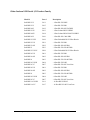
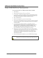
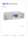
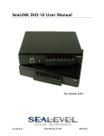
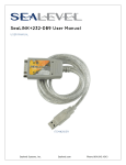
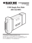
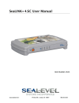
SeaLINK+4.VC User Manual
Part Number 2407
www.sealevel.com
PO Box 830 – Liberty, SC 29657
864.843.4343
Table of Contents
INTRODUCTION......................................................................................................................... 1
OTHER SEALEVEL USB SERIAL I/O PRODUCT FAMILY ................................................................ 2
BEFORE YOU GET STARTED................................................................................................. 3
WHAT’S INCLUDED ...................................................................................................................... 3
OPTIONAL ITEMS.......................................................................................................................... 3
SOFTWARE INSTALLATION INSTRUCTIONS .................................................................. 4
WINDOWS 98/ME/2000/XP/VISTA™ OPERATING SYSTEMS ....................................................... 4
PHYSICAL INSTALLATION .................................................................................................... 5
TECHNICAL DESCRIPTION.................................................................................................... 6
CONNECTOR PIN ASSIGNMENTS (RJ45) ....................................................................................... 6
INTERFACE SELECTION ................................................................................................................ 6
OPTIONAL DC POWER ON PIN 5................................................................................................... 7
OPTIONAL RJ45 TO DB9 RS-232 ADAPTER ................................................................................. 7
RS-485 BIASING AND TERMINATION ........................................................................................... 7
ELECTRICAL CHARACTERISTICS ...................................................................................... 8
FEATURES .................................................................................................................................... 8
SPECIFICATIONS ........................................................................................................................... 8
APPENDIX A - TROUBLESHOOTING ................................................................................... 9
APPENDIX B - HOW TO GET ASSISTANCE ...................................................................... 10
APPENDIX C – ELECTRICAL INTERFACE ....................................................................... 11
RS-232 ...................................................................................................................................... 11
RS-485 ...................................................................................................................................... 11
APPENDIX D - ASYNCHRONOUS COMMUNICATIONS ................................................ 12
APPENDIX E – SILK SCREEN – 2407 PCB .......................................................................... 13
APPENDIX F - COMPLIANCE NOTICES ............................................................................ 14
FEDERAL COMMUNICATIONS COMMISSION STATEMENT ........................................................... 14
WARRANTY............................................................................................................................... 15
© Sealevel Systems, Inc.
SL9174 Revision 4/2007
SeaLINK+8.VC User Manual
Introduction
The Sealevel Systems SeaLINK+4.VC (Item# 2407) is a USB device that equips the
PC with four RS-232 or RS-485 Asynchronous serial ports. The SeaLINK+4.VC
supports RS-232 data rates up to 115.2K bps and RS-485 data rates up to 921.6K
bps. The box does not need to be opened nor are there any dipswitches to set. The
2407 is housed in an attractive plastic enclosure with a high-retention USB type "B"
connector that prevents accidental disconnection of the included USB cable.
The 2407 is USB bus powered, so no external power supply is required. For
conveniently powering serial peripherals, ordering options allow an external power
source up to be connected to a DC jack on the rear of the unit. The supplied power is
fused and connected to pin 5 on each of the four RJ45 connectors.
With the unique VersaCom multi-interface connector design included on the
SeaLINK+4.VC, both RS-232 and two-wire RS-485 signals are always present and
active on the RJ45 serial connectors. Simply select the appropriate pin out for RS232 or two-wire RS-485 on a port-by-port basis.
The SeaLINK+4.VC is designed to be used with a variety of Operating Systems
including Windows 98/ME/2000/XP. The SeaCOM API (Application Programmer
Interface) included on CD with the SeaLINK+4.VC provides a variety of useful
high-level function calls implemented as a Windows dynamic link library (DLL). In
addition to the API, SeaCOM includes sample code and utilities to simplify software
development.
© Sealevel Systems, Inc.
-1-
SeaLINK+8.VC User Manual
Other Sealevel USB Serial I/O Product Family
Model #
Part #
Description
SeaLINK+232
2101
- 1-Port RS-232 DB25
SeaLINK+232
2105
- 1-Port RS-232 DB9
SeaLINK+485
2102
- 1-Port RS-422/485/530 DB25
SeaLINK+232I
2103
- 1-Port Isolated RS-232 DB25
SeaLINK+485I
2104
- 1-Port Isolated RS-422/485/530 DB25
SeaLINK+422
2106
- 1-Port RS-422 Cable DB9
SeaLINK+232.PC
2108
- 1-Port Embedded RS-232 Box Header
SeaLINK+2/232
2201
- 2-Port RS-232 DB9
SeaLINK+2/485
2202
- 2-Port RS-422/485 DB9
SeaLINK+2
2203
- 2-Port RS-232/422/485 DB9
SeaLINK+2/232.PC
2208
- 2-Port Embedded RS-232 Box Header
SeaLINK+4/232
2401
- 4-Port RS-232 DB9
SeaLINK+4/485
2402
- 4-Port RS-422/485 DB9
SeaLINK+4
2403
- 4-Port RS-232/422/485 DB9
SeaLINK+4/232.RJ
2404
- 4-Port RS-232 RJ45
SeaLINK+4.VC
2407
- 4-Port RS-232/485 VersaCom
SeaLINK+8/232
2801
- 8-Port RS-232 DB9
SeaLINK+8/485
2802
- 8-Port RS-422/485 DB9
SeaLINK+8
2803
- 8-Port RS-232/422/485 DB9
SeaLINK+8/232.RJ
2804
- 8-Port RS-232 RJ45
SeaLINK+8.VC
2807
- 8-Port RS-232/485 VersaCom
SeaLINK+16/232.RJ
2161
- 16-Port RS-232 RJ45
SeaLINK+16.VC
2167
- 16-Port RS-232/485 VersaCom
© Sealevel Systems, Inc.
-2-
SeaLINK+8.VC User Manual
Before You Get Started
What’s Included
The SeaLINK+4.VC is shipped with the following items. If any of these items is
missing or damaged please contact Sealevel for replacement.
Item# 2407 – SeaLINK+4.VC USB 8-Port Serial Device
Item# CA179 – 72” USB ‘A’ to ‘B’ Device Cable
Item# LB116 – RS-232 RJ45 Serial Loopback
Item# LB115 – RS-485 RJ45 Serial Loopback
Sealevel SeaCOM Software CD
Optional Items
Depending upon your application, you are likely to find one or more of the
following items useful for interfacing the SeaLINK+4.VC. All items can be
purchased from our website (http://www.sealevel.com/) or by calling 864-843-4343.
DB9 Male to RJ45 Modular Adapter (Item# RJ9P-232)
Preconfigured for use with the SeaLINK+4.VC, this modular adapter converts
the RJ45 RS-232 pinout from the SeaLINK+4.VC to a DB9 male RS-232 serial
port. Standard CAT5 patch cables can be used to extend the serial port up to 50
feet away from the SeaLINK+4.VC.
DB25 Male to RJ45 Modular Adapter (Item# RJ25P-232)
Preconfigured for use with the SeaLINK+4.VC, this modular adapter converts
the RJ45 RS-232 pinout from the SeaLINK+4.VC to a DB25 male RS-232 serial
port. Standard CAT5 patch cables can be used to extend the serial port up to 50
feet away from the SeaLINL+16.VC.
DB9 Male to RJ45 Modular Adapter (Item# RJ9P8)
The RJ9P8 includes an RJ45 connector and converts it to a DB9 Male connector,
which allows the use of standard twisted pair cabling. The RJ9P8 ships
unassembled and can be configured for virtually any pin out.
DB25 Male to RJ45 Modular Adapter (Item# RJ25P8)
The RJ25P8 includes an RJ45 connector and converts it to a DB25 Male
connector, which allows the use of standard twisted pair cabling. The RJ25P8
ships unassembled and can be configured for virtually any pin out.
USB ‘A’ to ‘A’ Extension Cable, 3 Meters in Length (Item# CA214)
The CA214 is a fully rated USB extension cable that allows adding 3 meters
(USB maximum of 5 meters) to any existing USB cable. The cable has a type ‘A’
male connector on one end and a type ‘A’ female connector on the other end.
RJ45 Patch Cable, 7’ in Length (Item# CA246)
Standard 7’ CAT5 patch cable with one-to-one pinout.
RJ45 Patch Cable, 10’ in Length (Item# CA247)
Standard 10’ CAT5 patch cable with one-to-one pinout.
© Sealevel Systems, Inc.
-3-
SeaLINK+8.VC User Manual
Software Installation Instructions
Windows 98/ME/2000/XP/Vista™ Operating Systems
Do not connect the device to a USB port until the software is installed.
1. Start Windows.
2. Insert the Sealevel Software CD in to your CD drive.
3. If ‘Auto-Start’ is enabled the installation window will automatically appear.
Otherwise, navigate to the root directory of your CD drive and double-click
the ‘autorun.exe’ application to launch the installation window.
4. Select ‘Install Software’.
5. Select the Part Number for your device from the listing.
6. The setup file will automatically detect the operating environment and install
the proper components. Follow the information presented on the installation
screens that follow.
7. A screen may appear with the declaration: “The publisher cannot be
determined due to the problems below: Authenticode signature not found.”
Please select the ‘Yes’ button and proceed with the installation. This
declaration simply means that the Operating System is not aware of the
driver being loaded. It will not cause any harm to your system.
8. During setup, you may specify installation directories and other preferred
configurations. This program also adds entries to the system registry that are
necessary for specifying the operating parameters for each driver. An
uninstall option is included to remove the driver and all registry/INI file
entries from your system.
9. Proceed with the physical installation of your SeaLINK USB serial adapter.
NOTE:
Windows NT is not USB aware and thus cannot support this device.
© Sealevel Systems, Inc.
-4-
SeaLINK+8.VC User Manual
Physical Installation
The SeaLINK+4.VC can be connected to any spare USB port.
Do not connect the device to a USB port until the software has been fully
installed.
1. Connect the SeaLINK+4.VC to a USB port with the supplied CA179 USB device
cable.
2. The software drivers installed during setup will automatically recognize and
configure the device.
3. You should see one or more “New Hardware Found” windows, indicating the
actual device being created.
4. NOTE: The installation will repeat twice for each COM port (a total of 8 times
on the SeaLINK+4.VC). This is a limitation in the way Windows installs external
serial devices.
5. Next, view your system’s Device Manager.
6. You should have new COM: ports in the Ports (COM & LPT) Device Class
indicating the installation was successful.
7. You can access your new COM: port by using the assigned COM: identifier. This
assignment will vary from system to system.
8. To verify operation use Sealevel Systems supplied WinSSD diagnostic utility.
WinSSD can be found in the Start, Programs group.
The SeaLINK+4.VC is now ready for use.
© Sealevel Systems, Inc.
-5-
SeaLINK+8.VC User Manual
Technical Description
The SeaLINK+4.VC utilizes four USB UARTs. These chips feature programmable
baud rate, data format, 128 byte Dual Port TX Buffer, and 384 byte Dual Port RX
Buffer. The transceivers support data rates up to 921.6K bps.
Connector Pin Assignments (RJ45)
D+
RTS
TX
GND
NC
RX
CTS
D-
Name
RS-485 Data +
Request To Send
Transmit Data
Ground
No Connect
Receive Data
Clear To Send
RS-485 Data –
Pin #
1
2
3
4
5
6
7
8
Mode
Output
Output
Input
Input
Note: DCD, DSR, and RI are inputs that are not brought out on the RJ45 connector.
DSR and DCD are biased active and RI is biased inactive.
Interface Selection
With the unique VersaCom multi-interface connector design, both RS-232 and twowire RS-485 signals are always present and active on the RJ45 connectors. Simply
select the appropriate pin out for RS-232 or two-wire RS-485 on each individual
port. The unused interface on each connector should be left unconnected. All inputs
have appropriate biasing to keep them in an inactive state. If the unused interface
pins are connected to a cable, the outputs will attempt to drive the lines while the
inputs will attempt to interpret any voltage on the line as data, which can limit cable
length and may result in communication failures.
© Sealevel Systems, Inc.
-6-
SeaLINK+8.VC User Manual
Optional DC Power on Pin 5
The 2407 is USB bus powered, so no external power supply is required. For
conveniently powering serial peripherals, ordering options allow an external power
source up to be connected to a DC jack on the rear of the unit. The supplied power is
connected to pin 5 on each of the four RJ45 connectors. Each serial port utilizes an
auto-resetting fuse rated at 500mA. Ordering options are shown below:
Item# 2407-DC05
Configured for 5VDC input power using a 2.1mm DC jack
Item# 2407-DC12
Configured for 12VDC input power using a 1.3mm DC jack
Item# 2407-DC24
Configured for 24VDC input power using a 1.3mm DC jack
Optional RJ45 to DB9 RS-232 Adapter
Preconfigured for use with Sealevel USB RJ45-enabled serial adapters, the RJ45 to
DB9 modular adapter (item# RJ9P-232) converts the RJ45 RS-232 pin out to a DB9
male RS-232 serial port. Standard CAT5 patch cables can be used to extend the
serial port up to 50 feet away from the RJ45 port. The pin out for the RJ9P-232 is
shown below.
RS-485 Biasing and Termination
120Ω termination resistor always present
between Data+ and Data510Ω Biasing pull-up resistors on Data+
510Ω Biasing pull-down resistors on Data-
© Sealevel Systems, Inc.
-7-
SeaLINK+8.VC User Manual
Electrical Characteristics
Features
Provides four RJ45 serial ports with status LEDs
Allows RS-232 or RS-485 pin out selection on port-by-port basis
Housed in rugged, attractive plastic enclosure
Integrates transmit and receive LED indicators on each port
High-retention USB type “B” connector prevents accidental disconnection of
USB cable
Powered by USB connection
Specifications
Temperature Range
Operating:
Storage:
-0°C – 70°C
-50°C – 105°C
Power Requirements
+5VDC @ 500mA
Physical Dimensions
Length
9.2”
23.37 cm
Width
5.3”
13.46 cm
Height
1.7”
4.32 cm
Manufacturing
All Sealevel Systems Printed Circuit boards are built to UL 94V0 rating and are
100% electrically tested. These printed circuit boards are solder mask over bare
copper or solder mask over tin nickel.
© Sealevel Systems, Inc.
-8-
SeaLINK+8.VC User Manual
Appendix A - Troubleshooting
Sealevel Software is supplied with the Sealevel Systems adapter and may be used in
the troubleshooting procedures. Using this software and following these simple steps
can eliminate most common problems without the need to call Technical Support.
1. If your adapter isn’t working, first check to make sure that USB support is
enabled in the System BIOS and it is functioning properly in the operating
system. This can be done by using either the Windows 98/ME or Windows 2000
Device Manager.
2. Ensure that the Sealevel Systems software has been installed on the machine so
that the necessary files are in place to complete the installation.
3. When the SeaLINK+4.VC is configured properly, Sealevel’s WinSSD utility and
a loopback plug can be used to check communications. You can make a simple
Loopback in the field by connecting the TX and RX pins. If you decide to test the
Modem Control Signals, a full pin loopback plug will be required. Details on
loopback plugs are included within WinSSD. Contact Sealevel Systems if you
need further assistance.
4. When testing the SeaLINK+4.VC in loopback mode, you should see both the TD
and RD echoed as data on the screen. The loopback test first transmits a HEX
pattern, 55AA, and then an ASCII string of data. If this test passes, then the
SeaLINK+4.VC is ready for use in your application.
5. Always use the Sealevel Systems diagnostic software when troubleshooting a
problem. This will eliminate any software issues from the equation.
If these steps do not solve your problem, please call Sealevel Systems’ Technical
Support, (864) 843-4343. Our technical support is free and available from 8:00 AM
to 5:00 PM Eastern Time Monday through Friday. For email support contact
[email protected].
© Sealevel Systems, Inc.
-9-
SeaLINK+8.VC User Manual
Appendix B - How To Get Assistance
Begin by reading through the Trouble Shooting Guide in Appendix A. If assistance
is still needed please see below.
When calling for technical assistance, please have your user manual and current
adapter settings. If possible, please have the adapter installed in a computer ready to
run diagnostics.
Sealevel Systems provides an FAQ section on its web site. Please refer to this to
answer many common questions. This section can be found at
http://www.sealevel.com/faq.asp
Sealevel Systems maintains a Home page on the Internet. Our home page address is
http://www.sealevel.com. The latest software updates, and newest manuals are
available via our FTP site that can be accessed from our home page.
Technical support is available Monday to Friday from 8:00 AM to 5:00 PM eastern
time. Technical support can be reached at (864) 843-4343.
RETURN AUTHORIZATION MUST BE OBTAINED FROM SEALEVEL
SYSTEMS BEFORE RETURNED MERCHANDISE WILL BE ACCEPTED.
AUTHORIZATION CAN BE OBTAINED BY CALLING SEALEVEL
SYSTEMS AND REQUESTING A RETURN MERCHANDISE
AUTHORIZATION (RMA) NUMBER.
© Sealevel Systems, Inc.
- 10 -
SeaLINK+8.VC User Manual
Appendix C – Electrical Interface
RS-232
Quite possibly the most widely used communication standard is RS-232. This
implementation has been defined and revised several times and is often referred
to as RS-232 or EIA/TIA-232. The IBM PC computer defined the RS-232 port
on a 9 pin D sub connector and subsequently the EIA/TIA approved this
implementation as the EIA/TIA-574 standard. This standard is defined as the
9-Position Non-Synchronous Interface between Data Terminal Equipment and
Data Circuit-Terminating Equipment Employing Serial Binary Data Interchange.
Both implementations are in wide spread use and will be referred to as RS-232 in
this document. RS-232 is capable of operating at data rates up to 20 Kbps at
distances less than 50 ft. The absolute maximum data rate may vary due to line
conditions and cable lengths. RS-232 is a single ended or unbalanced interface,
meaning that a single electrical signal is compared to a common signal (ground)
to determine binary logic states. The RS-232 and the EIA/TIA-574 specification
define two types of interface circuits, Data Terminal Equipment (DTE) and Data
Circuit-Terminating Equipment (DCE). The SeaLINK+4.VC is a DTE device.
RS-485
RS-485 is backwardly compatible with RS-422; however, it is optimized for
partyline or multi-drop applications. The output of the RS-422/485 driver is
capable of being Active (enabled) or Tri-State (disabled). This capability allows
multiple ports to be connected in a multi-drop bus and selectively polled. RS-485
allows cable lengths up to 4000 feet and data rates up to 10 Megabits per second.
The signal levels for RS-485 are the same as those defined by RS-422. RS-485
has electrical characteristics that allow for 32 drivers and 32 receivers to be
connected to one line. This interface is ideal for multi-drop or network
environments. RS-485 tri-state driver (not dual-state) will allow the electrical
presence of the driver to be removed from the line. Only one driver may be active
at a time and the other driver(s) must be tri-stated. RS-485 can be cabled in two
ways, two wire and four wire mode. Two wire mode does not allow for full
duplex communication, and requires that data be transferred in only one direction
at a time. For half-duplex operation, the two transmit pins should be connected to
the two receive pins (Tx+ to Rx+ and Tx- to Rx-). Four wire mode allows full
duplex data transfers. RS-485 does not define a connector pin-out or a set of
modem control signals. RS-485 does not define a physical connector.
© Sealevel Systems, Inc.
- 11 -
SeaLINK+8.VC User Manual
Appendix D - Asynchronous Communications
Serial data communications implies that individual bits of a character are transmitted
consecutively to a receiver that assembles the bits back into a character. Data rate,
error checking, handshaking, and character framing (start/stop bits) are pre-defined
and must correspond at both the transmitting and receiving ends.
Asynchronous communications is the standard means of serial data communication
for PC compatibles and PS/2 computers. The original PC was equipped with a
communication or COM: port that was designed around an 8250 Universal
Asynchronous Receiver Transmitter (UART). This device allows asynchronous serial
data to be transferred through a simple and straightforward programming interface. A
starting bit followed by a pre-defined number of data bits (5, 6, 7, or 8) defines
character boundaries for asynchronous communications. The end of the character is
defined by the transmission of a pre-defined number of stop bits (usually 1, 1.5 or 2).
An extra bit used for error detection is often appended before the stop bits.
Idle state of
line
5 to 8 Data Bits
Odd, Even
or
Unused
Remain Idle or
next start bit
1
P
BIT
STOP
0
1
1.5
2
This special bit is called the parity bit. Parity is a simple method of determining if a
data bit has been lost or corrupted during transmission. There are several methods for
implementing a parity check to guard against data corruption. Common methods are
called (E)ven Parity or (O)dd Parity. Sometimes parity is not used to detect errors on
the data stream. This is refereed to as (N)o parity. Because each bit in asynchronous
communications is sent consecutively, it is easy to generalize asynchronous
communications by stating that each character is wrapped (framed) by pre-defined
bits to mark the beginning and end of the serial transmission of the character. The
data rate and communication parameters for asynchronous communications have to
be the same at both the transmitting and receiving ends. The communication
parameters are baud rate, parity, number of data bits per character, and stop bits (i.e.
9600, N, 8, 1).
© Sealevel Systems, Inc.
- 12 -
SeaLINK+8.VC User Manual
Appendix E – Silk Screen – 2407 PCB
© Sealevel Systems, Inc.
- 13 -
SeaLINK+8.VC User Manual
Appendix F - Compliance Notices
Federal Communications Commission Statement
FCC - This equipment has been tested and found to comply with the limits for Class
A digital device, pursuant to Part 15 of the FCC Rules. These limits are designed to
provide reasonable protection against harmful interference when the equipment is
operated in a commercial environment. This equipment generates, uses, and can
radiate radio frequency energy and, if not installed and used in accordance with the
instruction manual, may cause harmful interference to radio communications.
Operation of this equipment in a residential area is likely to cause harmful
interference in such case the user will be required to correct the interference at the
users expense.
EMC Directive Statement
Products bearing the CE Label fulfill the requirements of the EMC directive
(89/336/EEC) and of the low-voltage directive (73/23/EEC) issued by the European
Commission.
To obey these directives, the following European standards must be met:
EN55022 Class A - “Limits and methods of measurement of radio interference
characteristics of information technology equipment”
EN55024 – “Information technology equipment Immunity characteristics Limits and
methods of measurement”.
EN60950 (IEC950) - “Safety of information technology equipment, including
electrical business equipment”
Warning
This is a Class A Product. In a domestic environment, this product may cause
radio interference in which case the user may be required to take adequate
measures to prevent or correct the interference.
Always use cabling provided with this product if possible. If no cable is provided or
if an alternate cable is required, use high quality shielded cabling to maintain
compliance with FCC/EMC directives.
© Sealevel Systems, Inc.
- 14 -
SeaLINK+8.VC User Manual
Warranty
Sealevel's commitment to providing the best I/O solutions is reflected in the Lifetime
Warranty that is standard on all Sealevel manufactured products. We are able to
offer this warranty due to our control of manufacturing quality and the historically
high reliability of our products in the field. Sealevel products are designed and
manufactured at its Liberty, South Carolina facility, allowing direct control over
product development, production, burn-in and testing.
Sealevel Systems, Inc. (hereafter "Sealevel") warrants that the Product shall conform
to and perform in accordance with published technical specifications and shall be
free of defects in materials and workmanship for life. In the event of failure,
Sealevel will repair or replace the product at Sealevel's sole discretion. Failures
resulting from misapplication or misuse of the Product, failure to adhere to any
specifications or instructions, or failure resulting from neglect or abuse are not
covered under this warranty.
Warranty service is obtained by delivering the Product to Sealevel and providing
proof of purchase. Return authorization must be obtained from Sealevel Systems
before returned merchandise will be accepted. Authorization is obtained by
calling Sealevel Systems and requesting a Return Merchandise Authorization
(RMA) number. The Customer agrees to insure the Product or assume the risk of
loss or damage in transit, to prepay shipping charges to Sealevel, and to use the
original shipping container or equivalent. Warranty is valid only for original
purchaser and is not transferable.
Sealevel Systems assumes no liability for any damages, lost profits, lost savings or
any other incidental or consequential damage resulting from the use, misuse of, or
inability to use this product. Sealevel Systems will not be liable for any claim made
by any other related party.
This warranty applies to Sealevel manufactured Product. Product purchased through
Sealevel but manufactured by a third party will retain the original manufacturer's
warranty.
Sealevel Systems, Incorporated
2779 Greenville Highway
P.O. Box 830
Liberty, SC 29657 USA
(864) 843-4343
FAX: (864) 843-3067
www.sealevel.com
email: [email protected]
Technical Support is available Monday - Friday from 8 a.m. to 5 p.m. Eastern time
Trademarks
Sealevel Systems, Incorporated acknowledges that all trademarks referenced in this
manual are the service mark, trademark, or registered trademark of the respective
company.
© Sealevel Systems, Inc.
- 15 -
SeaLINK+8.VC User Manual