1
Acer Aspire 1710 Series
Service Guide
Project Code: A15
Please note that Aspire 1710 has the same housing with Aspire 1700. And this model will not have service CD.
Please refer to Aspire 1700 service CD (Part No.: VD.A08V7.001) for disassembling mpeg files.
PRINTED IN TAIWAN
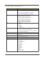
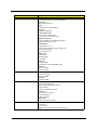
Revision History
Please refer to the table below for the updates made on Aspire 1710 service guide.
Date
II
Chapter
Updates
Copyright
Copyright © 2004 by Acer Incorporated. All rights reserved. No part of this publication may be reproduced,
transmitted, transcribed, stored in a retrieval system, or translated into any language or computer language, in
any form or by any means, electronic, mechanical, magnetic, optical, chemical, manual or otherwise, without
the prior written permission of Acer Incorporated.
Disclaimer
The information in this guide is subject to change without notice.
Acer Incorporated makes no representations or warranties, either expressed or implied, with respect to the
contents hereof and specifically disclaims any warranties of merchantability or fitness for any particular
purpose. Any Acer Incorporated software described in this manual is sold or licensed "as is". Should the
programs prove defective following their purchase, the buyer (and not Acer Incorporated, its distributor, or its
dealer) assumes the entire cost of all necessary servicing, repair, and any incidental or consequential
damages resulting from any defect in the software.
Intel is a registered trademark of Intel Corporation.
Pentium and Pentium II/III are trademarks of Intel Corporation.
Other brand and product names are trademarks and/or registered trademarks of their respective holders.
III
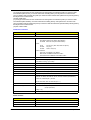
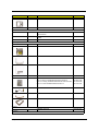
Conventions
The following conventions are used in this manual:
IV
Screen messages
Denotes actual messages that appear
on screen.
NOTE
Gives bits and pieces of additional
information related to the current
topic.
WARNING
Alerts you to any damage that might
result from doing or not doing specific
actions.
CAUTION
Gives precautionary measures to
avoid possible hardware or software
problems.
IMPORTANT
Reminds you to do specific actions
relevant to the accomplishment of
procedures.
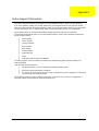
Preface
Before using this information and the product it supports, please read the following general information.
1.
This Service Guide provides you with all technical information relating to the BASIC CONFIGURATION
decided for Acer "global" product offering. To better fit local market requirements and enhance product
competitiveness, your regional office MAY have decided to extend the functionality of a machine (e.g.
add-on card, modem, or extra memory capability). These LOCALIZED FEATURES will NOT be covered
in this generic service guide. In such cases, please contact your regional offices or the responsible
personnel/channel to provide you with further technical details.
2.
Please note WHEN ORDERING FRU PARTS, that you should check the most up-to-date information
available on your regional web or channel. If, for whatever reason, a part number change is made, it will
not be noted in the printed Service Guide. For ACER AUTHORIZED SERVICE PROVIDERS, your Acer
office may have a DIFFERENT part number code to those given in the FRU list of this printed Service
Guide. You MUST use the list provided by your regional Acer office to order FRU parts for repair and
service of customer machines.
V
VI
Table of Contents
Chapter 1
System Introduction
1
Features . . . . . . . . . . . . . . . . . . . . . . . . . . . . . . . . . . . . . . . . . . . . . . . . . . . . . . . . . . . .1
Display . . . . . . . . . . . . . . . . . . . . . . . . . . . . . . . . . . . . . . . . . . . . . . . . . . . . . . . . . . . . .3
System Block Diagram . . . . . . . . . . . . . . . . . . . . . . . . . . . . . . . . . . . . . . . . . . . . . . . . .4
Board Layout . . . . . . . . . . . . . . . . . . . . . . . . . . . . . . . . . . . . . . . . . . . . . . . . . . . . . . . .5
Top View . . . . . . . . . . . . . . . . . . . . . . . . . . . . . . . . . . . . . . . . . . . . . . . . . . . . . . . .5
Bottom View . . . . . . . . . . . . . . . . . . . . . . . . . . . . . . . . . . . . . . . . . . . . . . . . . . . . .7
Panel . . . . . . . . . . . . . . . . . . . . . . . . . . . . . . . . . . . . . . . . . . . . . . . . . . . . . . . . . . . . . . .8
Front Panel . . . . . . . . . . . . . . . . . . . . . . . . . . . . . . . . . . . . . . . . . . . . . . . . . . . . . .8
Closed front view . . . . . . . . . . . . . . . . . . . . . . . . . . . . . . . . . . . . . . . . . . . . . . . . .9
Left view . . . . . . . . . . . . . . . . . . . . . . . . . . . . . . . . . . . . . . . . . . . . . . . . . . . . . . .10
Right view . . . . . . . . . . . . . . . . . . . . . . . . . . . . . . . . . . . . . . . . . . . . . . . . . . . . . .11
Rear Panel . . . . . . . . . . . . . . . . . . . . . . . . . . . . . . . . . . . . . . . . . . . . . . . . . . . . .12
Bottom Panel . . . . . . . . . . . . . . . . . . . . . . . . . . . . . . . . . . . . . . . . . . . . . . . . . . .13
Indicators . . . . . . . . . . . . . . . . . . . . . . . . . . . . . . . . . . . . . . . . . . . . . . . . . . . . . . . . . .14
Keyboard . . . . . . . . . . . . . . . . . . . . . . . . . . . . . . . . . . . . . . . . . . . . . . . . . . . . . . . . . .16
Special keys . . . . . . . . . . . . . . . . . . . . . . . . . . . . . . . . . . . . . . . . . . . . . . . . . . . .16
Touchpad . . . . . . . . . . . . . . . . . . . . . . . . . . . . . . . . . . . . . . . . . . . . . . . . . . . . . . . . . .20
Touchpad basics . . . . . . . . . . . . . . . . . . . . . . . . . . . . . . . . . . . . . . . . . . . . . . . . .20
Launch Keys . . . . . . . . . . . . . . . . . . . . . . . . . . . . . . . . . . . . . . . . . . . . . . . . . . . . . . . .21
Hardware Specifications and Configurations . . . . . . . . . . . . . . . . . . . . . . . . . . . . . . .22
Chapter 2
System Utilities
32
BIOS Setup Utility . . . . . . . . . . . . . . . . . . . . . . . . . . . . . . . . . . . . . . . . . . . . . . . . . . . .32
Navigating the BIOS Utility . . . . . . . . . . . . . . . . . . . . . . . . . . . . . . . . . . . . . . . . .33
Info. . . . . . . . . . . . . . . . . . . . . . . . . . . . . . . . . . . . . . . . . . . . . . . . . . . . . . . . . . . .34
Main . . . . . . . . . . . . . . . . . . . . . . . . . . . . . . . . . . . . . . . . . . . . . . . . . . . . . . . . . .35
Advanced . . . . . . . . . . . . . . . . . . . . . . . . . . . . . . . . . . . . . . . . . . . . . . . . . . . . . .37
Security . . . . . . . . . . . . . . . . . . . . . . . . . . . . . . . . . . . . . . . . . . . . . . . . . . . . . . . .38
Boot . . . . . . . . . . . . . . . . . . . . . . . . . . . . . . . . . . . . . . . . . . . . . . . . . . . . . . . . . . .42
Exit . . . . . . . . . . . . . . . . . . . . . . . . . . . . . . . . . . . . . . . . . . . . . . . . . . . . . . . . . . .43
BIOS Flash Utility . . . . . . . . . . . . . . . . . . . . . . . . . . . . . . . . . . . . . . . . . . . . . . . . . . . .44
Chapter 3
Machine Disassembly and Replacement
46
General Information . . . . . . . . . . . . . . . . . . . . . . . . . . . . . . . . . . . . . . . . . . . . . . . . . .47
Before You Begin . . . . . . . . . . . . . . . . . . . . . . . . . . . . . . . . . . . . . . . . . . . . . . . .47
Disassembly Procedure Flowchart . . . . . . . . . . . . . . . . . . . . . . . . . . . . . . . . . . . . . . .48
Disassembling . . . . . . . . . . . . . . . . . . . . . . . . . . . . . . . . . . . . . . . . . . . . . . . . . . . . . .51
Remove the battery . . . . . . . . . . . . . . . . . . . . . . . . . . . . . . . . . . . . . . . . . . . . . . .51
Remove the HDD module . . . . . . . . . . . . . . . . . . . . . . . . . . . . . . . . . . . . . . . . . .51
Remove the combo drive . . . . . . . . . . . . . . . . . . . . . . . . . . . . . . . . . . . . . . . . . .51
Remove the thermal module . . . . . . . . . . . . . . . . . . . . . . . . . . . . . . . . . . . . . . . .52
Remove CPU . . . . . . . . . . . . . . . . . . . . . . . . . . . . . . . . . . . . . . . . . . . . . . . . . . .52
Remove the memory . . . . . . . . . . . . . . . . . . . . . . . . . . . . . . . . . . . . . . . . . . . . . .52
Remove VGA card . . . . . . . . . . . . . . . . . . . . . . . . . . . . . . . . . . . . . . . . . . . . . . .52
Detach the wireless card . . . . . . . . . . . . . . . . . . . . . . . . . . . . . . . . . . . . . . . . . . .53
Remove moden card . . . . . . . . . . . . . . . . . . . . . . . . . . . . . . . . . . . . . . . . . . . . . .53
Remove the inverter cover . . . . . . . . . . . . . . . . . . . . . . . . . . . . . . . . . . . . . . . . .53
Detach the upper system cover . . . . . . . . . . . . . . . . . . . . . . . . . . . . . . . . . . . . .54
Remove the LCD module . . . . . . . . . . . . . . . . . . . . . . . . . . . . . . . . . . . . . . . . . .54
Remove the LCD panel . . . . . . . . . . . . . . . . . . . . . . . . . . . . . . . . . . . . . . . . . . . .55
Remove the inverter board . . . . . . . . . . . . . . . . . . . . . . . . . . . . . . . . . . . . . . . . .55
Remove the mylars . . . . . . . . . . . . . . . . . . . . . . . . . . . . . . . . . . . . . . . . . . . . . . .57
Remove the wireless module . . . . . . . . . . . . . . . . . . . . . . . . . . . . . . . . . . . . . . .57
VII
Table of Contents
Remove the side bracket . . . . . . . . . . . . . . . . . . . . . . . . . . . . . . . . . . . . . . . . . .57
Remove the LED cable attached on the LCD outer shield . . . . . . . . . . . . . . . . .58
Remove the subwoofer . . . . . . . . . . . . . . . . . . . . . . . . . . . . . . . . . . . . . . . . . . . .58
Release the MDC cable . . . . . . . . . . . . . . . . . . . . . . . . . . . . . . . . . . . . . . . . . . .59
Disconnect the cable to the modem header . . . . . . . . . . . . . . . . . . . . . . . . . . . .59
Remove the keyboard . . . . . . . . . . . . . . . . . . . . . . . . . . . . . . . . . . . . . . . . . . . . .59
Remove the LED board . . . . . . . . . . . . . . . . . . . . . . . . . . . . . . . . . . . . . . . . . . .59
Detach the front panel . . . . . . . . . . . . . . . . . . . . . . . . . . . . . . . . . . . . . . . . . . . . .60
Remove the Audio DJ board . . . . . . . . . . . . . . . . . . . . . . . . . . . . . . . . . . . . . . . .61
Remove the touch pad . . . . . . . . . . . . . . . . . . . . . . . . . . . . . . . . . . . . . . . . . . . .61
Remove the touch pad board . . . . . . . . . . . . . . . . . . . . . . . . . . . . . . . . . . . . . . .62
Remove the lid switch cable . . . . . . . . . . . . . . . . . . . . . . . . . . . . . . . . . . . . . . . .62
Remove the floppy drive . . . . . . . . . . . . . . . . . . . . . . . . . . . . . . . . . . . . . . . . . . .62
Remove the speaker set . . . . . . . . . . . . . . . . . . . . . . . . . . . . . . . . . . . . . . . . . . .63
Remove the mainboard . . . . . . . . . . . . . . . . . . . . . . . . . . . . . . . . . . . . . . . . . . . .64
Remove the system fan . . . . . . . . . . . . . . . . . . . . . . . . . . . . . . . . . . . . . . . . . . .64
FDD Module . . . . . . . . . . . . . . . . . . . . . . . . . . . . . . . . . . . . . . . . . . . . . . . . . . . .65
HDD Module . . . . . . . . . . . . . . . . . . . . . . . . . . . . . . . . . . . . . . . . . . . . . . . . . . . .66
Combo Module . . . . . . . . . . . . . . . . . . . . . . . . . . . . . . . . . . . . . . . . . . . . . . . . . .66
Chapter 4
Troubleshooting
68
System Check Procedures . . . . . . . . . . . . . . . . . . . . . . . . . . . . . . . . . . . . . . . . . . . . .69
External Diskette Drive Check . . . . . . . . . . . . . . . . . . . . . . . . . . . . . . . . . . . . . .69
External CD-ROM Drive Check . . . . . . . . . . . . . . . . . . . . . . . . . . . . . . . . . . . . .69
Keyboard or Auxiliary Input Device Check . . . . . . . . . . . . . . . . . . . . . . . . . . . . .69
Memory check . . . . . . . . . . . . . . . . . . . . . . . . . . . . . . . . . . . . . . . . . . . . . . . . . . .70
Power System Check . . . . . . . . . . . . . . . . . . . . . . . . . . . . . . . . . . . . . . . . . . . . .70
Touchpad Check . . . . . . . . . . . . . . . . . . . . . . . . . . . . . . . . . . . . . . . . . . . . . . . . .72
Power-On Self-Test (POST) Error Message . . . . . . . . . . . . . . . . . . . . . . . . . . . . . . .73
Index of Error Messages . . . . . . . . . . . . . . . . . . . . . . . . . . . . . . . . . . . . . . . . . . . . . . .74
Index of Symptom-to-FRU Error Message . . . . . . . . . . . . . . . . . . . . . . . . . . . . . . . . .77
Intermittent Problems . . . . . . . . . . . . . . . . . . . . . . . . . . . . . . . . . . . . . . . . . . . . . . . . .80
Undetermined Problems . . . . . . . . . . . . . . . . . . . . . . . . . . . . . . . . . . . . . . . . . . . . . . .81
Chapter 5
Jumper and Connector Locations
82
Top View . . . . . . . . . . . . . . . . . . . . . . . . . . . . . . . . . . . . . . . . . . . . . . . . . . . . . . .82
Bottom View . . . . . . . . . . . . . . . . . . . . . . . . . . . . . . . . . . . . . . . . . . . . . . . . . . . .84
Chapter 6
FRU (Field Replaceable Unit) List
Appendix A Model Definition and Configuration
86
96
Model Name Definition . . . . . . . . . . . . . . . . . . . . . . . . . . . . . . . . . . . . . . . . . . . . . . . .96
Appendix B Test Compatible Components
98
Microsoft Windows XP Environment Test . . . . . . . . . . . . . . . . . . . . . . . . . . . . . . . . . .99
Appendix C Online Support Information
106
Index
108
VIII
Table of Contents
IX
Chapter 1
System Introduction
Features
This computer was designed with the user in mind. Here are just a few of its many features:
Performance
T
Intel® Pentium® 4 FSB 800 processors
T
L2 cache 1MB
T
Intel 865G with ICH-5, support 800MHz Front Side Bus, dual channel and HTT support
T
80 GB or higher-capacity Desktop 5400rpm, 7200rpm HDD
T
Microsoft® Windows® XP Home/Pro operating system
T
Optional 6-in-1 Multimedia memory card reader module
Multimedia
T
DVD/CD-RW combo
T
DVD Dual drive
T
Audio input and output jacks
T
Hardware 3D graphic engine
T
Two stereo speakers+one sub-woofer
T
17” Desktop SXGA LCD, 1280x1024, 16M colors
Connectivity
T
Modem: Software Modem V.92 56Kbps (MDC)
T
10/100/1000 Mbps Gigabit Ethernet LAN
T
Optional Mini-PCI 802.11g or 802.11 a/g
T
One switch to enable or disable wireless function
T
Keyboard and pointing device
T
Four universal serial but (UBS) ports 2.0
T
Two IEEE 1394 ports
T
Bluetooth ready (manufacturing option)
Expansion
T
PC card slot enableing a range of add-on options
T
Upgrageable CPU, hard disk and memory modules
T
One type II PC Card slot (PCMCIA and CardBus)
T
One RJ-11 modem jack (V.92, 56K)
T
One RJ-45 network jack (Gigabit Ethernet)
T
One DC-in port (AC adapter)
T
One parallel port (ECP/EPP)
I/O Ports
Chapter 1
1
T
One external monitor port
T
Two IEEE 1394 ports
T
One PS/2 port
T
One microphone-in jack (3.5mm mini jack)
T
One headphone jack (3.5mm mini jack)
T
Four Universal Serial Bus (USB) ports
Display and video
T
17” Desktop liquid-crystal display (LCD) at 1280 x 1024 Super Graphics Array (SXGA) resolution
T
Simultaneous LCD and CRT display
T
Dual independent display support
T
Hardware 3D graphic engine
T
16-bit stereo audio (AC’97)
T
Two built-in stereo speakers
T
Audio ports for microphone-in and headphones
Audio
Human-centric design and ergonomics
2
T
All-in-one design (incorporating hard drive, optical drive and floppy disk drive)
T
Rugged and space saving
T
Full-size desktop keyboard
T
No need to turn on the system for playing CD or MP3
T
Large & comfortable palm rest area with well-positioned touchpad
Aspire 1710
Display
The 17” display panel provides a large viewing area for maximum efficiency and ease-of-use. The liquid crystal
display (LCD) supports SXGA resolution with 16 million colors at 1280 x 1024.
Video Performance
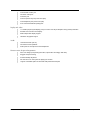
Your Aspire 1710 series computer features an accelerated graphics port (AGP) video system with Intel 865G
embedded VGA engine and 64MB UMA RAM, and nVIDIA NV-34M/NV-36M series (64M/128M AGP card) as
an option. This provides a robust solution, while enabling high quality video output.
Simultaneous display
Your computer’s large display, combined with its multimedia capabilities, makes it ideally suited to delivering
presentations.
You can also connect an external monitor or projector, and then choose to use the computer’s LCD panel only,
the external device only, or the LCD panel and external device simultaneously.
Simultaneous display allows you to manage a presentation on your computer, while your audience watches
the monitor or projector screen.
Chapter 1
3
4
A
B
C
D
AD18
AD19
1394
MINI-PCI
N/A
3
2
1
0
8
0
15" XGA
1
1
7
E,F
D
C
B
A, C
IRQ
PAGE 17
PAGE 17
PAGE 17
7
PAGE 17
KB/MS
PAGE 26
Keyboard
Connector
PAGE 17
PAGE 20
LPT
PAGE 22
COM
LED Board
Connector
USB3
USB5
USB7
PAGE 14
PAGE 14
FDD
5
LPC
4
USB0
4
Card Reader
Connector
MDC Slot
Mini-PCI
Slot
PCMCIA
Slot
PAGE 25
ENE/CB1410
Card Bus
PCI Board
USB1/MDC
PCI
PCI
PAGE 18
NS/LM4871LD
Audio Amp
PAGE 25
NS/LM4873MTE
3
PAGE 19
RJ11
PAGE 25
Sub-woofer
PAGE 25
Speaker
PAGE 25
USB 0,1
Headphone
PAGE 24
MIC-IN
PAGE 27
Audio DJ Board
Connector
1394
PAGE 21
1394
PAGE 21
PAGE 19
RJ45
PAGE 15
L
O
N
G
D
I
M
M
AC97
Audio Amp
PAGE 24
Realtek/ALC202
Audio Codec
PAGE 27
O2/ OZ263
Audio DJ
PAGE 21
TI/TSB43AB22A
1394 PHY
PAGE 19
Broadcom/BCM5788M
GbE LAN MAC+PHY
PAGE 15
L
O
N
G
D
I
M
M
3
PCI
LPC
PCI
PCI
DDR SDRAM
266/333/400MHz
PCI Board
Connector
PAGE : 9,10,11
Intel 82801EB
(ICH5)
(mBGA 460)
SOUTH BRIDGE
PAGE 23
FAN2
PAGE 26
HUB I/F
PAGE : 05,06,07,08
NORTH BRIDGE
Intel 82865G
(GMCH)
(FC-BGA 932)
Host Bus
(400/533/800MHz)
PAGE : 03,04
266MB/s,1.5V
FAN1
NS/PC87391
(100 Pins
TQFP)
PAGE 23
6
EC
PAGE 26
BIOS
DT3
5
INTEL P4 CPU
Northwood/ Prescott
(FCPGA 478)
NS/PC87591
(176 Pin LQFP)
USB
SECONDARY IDE
Super IO
PS2
RGB
Y/C
PRIMARY IDE
PAGE 14
CRT
PAGE 20
S-Video
KEY MATRIX
PAGE 17
PAGE 17
PAGE 17
USB2
USB4
PAGE 20
CDROM
PAGE 20
HDD
RGB
Y/C
PAGE 13
AGP Connector
Y/C RGB AGP 8X BUS
ATi or nVIDIA
AGP 8X BUS
AGP Board
Graphic Chip
LVDS
PAGE 17
1
1
6
LVDS
Panel
USB6
Touchpad Board
Connector
1
17" SXGA
LCD Panel
AD17
Card bus
REQ/GNT #
LCD ID2
LCD ID1
LCD ID0
SB
SB
SB
PANEL_ID2 PANEL_ID1 PANEL_ID0
N/A
AD16
AGP
LAN
IDSEL #
8
PCI DEVICES
Date:
2
Saturday, November 29, 2003
PAGE : 28
BATTERY & ACIN
RTC
PAGE : 22
Power
PAGE : 12
ICS952623
GEN.
CLOCK
Main
1
VTT_NB
Sheet
1
2
of
PAGE : 29
POWER
PAGE : 33
POWER CORE
PAGE : 32
34
POWER DISCHARGE
PAGE : 30
SYSTEM POWER
PAGE : 32
2.5VSUS&DDR_VTT
PAGE : 34
12V_HDD & 5V_HDD
DIAGRAM
VTT_NB
VCCVID
VCC_CORE
+1.5V
+3V
3V-S5
+5V
3VSUS
5VSUS
3V_591
5VPCU
+2.5V
DDR_VTT
2.5VSUS
VCC2.5_M
12V_HDD
5V_HDD
VAD
VA2
VIN
VCCRTC
1*SRC/SRC#
2*48MHz
2*REF
7*PCI
3*PCIF
5*3V66
1*SDRAM
3*CPU/CPU-
Size
Document Number
Custom
BLOCK
2
Rev
1A
A
B
C
D
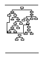
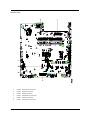
System Block Diagram
Aspire 1710
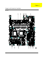
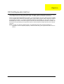
Board Layout
Top View
Chapter 1
5
6
1
PS2 Port
16
Mini 1394 Connector
2
Parallel Port
17
MIC Connector
3
LAN Connector
18
Line Out Connector
4
CPU Fan Connector
19
Woofer Connector
5
COM1 Port
20
VGA Board Connector
6
VGA Port
21
Battery Connector
7
S-Video Port
22
RTC Battery Connector
8
Modem Connector
23
PCI Board Connector
9
MDC Connector
24
HDD Connector
11
USB Port
25
CD/DVD-ROM Module Connector
12
DC-In Connector
26
HDD Power Connector
13
CPU Socket
27
DDR RAM Socket-1
14
USB Port
28
DDR RAM Socket-2
15
1394 Connector
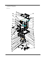
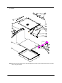
Aspire 1710
Bottom View
1
Audio DJ FFC Connector
2
Keyboard Connector
3
Speaker Connector
4
LED Board FFC Connector
5
FDD FFC Connector
6
Touchpad FFC Connector
Chapter 1
7
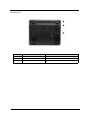
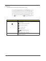
Panel
Ports allow you to connect peripheral devices to your computer as you would with a desktop PC.
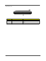
Front Panel
#
Item
Description
1
Display
Large liquid crystal display (LCD) provides visual output.
2
Power button
Turns the computer on and off.
3
Keyboard
Full-size keyboard for inputing typed data.
4
Touchpad
Touch sensitive pad that functions like a computer mouse.
5
Click buttons & scroll key
Right and left buttons that provide the same functions as
buttons on a computer mouse. The scroll key scrolls the
contents of a window up and down.
6
Audio DJ controls and indicator
Buttons and indicators for the Audio DJ function.
7
Palm rest
Provides a comfortable platform for your hands when
typing on the keyboard.
8
Launch keys
1 switch button for wired/wireless LAN, or Bluetooth
(optional)
1 e-mail launch button
1 launch button for Internet browser
2 programmable buttons
9
8
Status indicators
Light emitting diodes (LEDs) that show the status of the
computer and its components.
Aspire 1710
Closed front view
#
Item
Description
1
Speakers
Left and right speakers deliver stereo audio output.
2
Wireless communication indicator
Lights when the Wireless LAN, or Bluetooth, capability is
enabled.
3
Power indicator
Lights when the computer is on.
Chapter 1
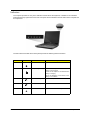
9
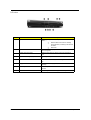
Left view
#
1
10
Item/ Port
Optical drive
Description
Depending on your model, the optical drive is one of the
followin:
T
DVD/CD-RW combo drive for reading
CDs and DVDs, and writing to CD-Rs and
CD-RWs.
T
DVD Dual
2
Optical disc read indicator
Light emitting diode (LED) that indicates when an optical
disc is being read.
3
Optical drive eject button
Press the eject button to remove a disc from the optical
drive.
4
Optical drive emergency eject hole
Used to eject an optical disc when the computer is turned
off.
5
Left latch
Locks and release the lid (one on the right and one on the
left).
6
Floppy drive/Card reader
Accepts a 3.5 inch floppy disk, or a 6-in-1 card reader
(optional).
7
PC card eject button
Press the eject button to remove a PC card from the PC
card slot.
8
PC card slot
The slot supports a standard Type II PC card (PCMCIA).
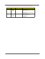
Aspire 1710
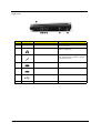
Right view
#
Icon
Item/ Port
Description
1
Right latch
Locks and releases the lid (one on the right
and one on the left.)
2
Speaker/Headphone-out jack
Connects to audio line-out devices (e.g.
speakers, headphones).
3
Line-in/Mic-in jack
Accepts audio line-in devices (e.g. audio CD
player, stereo walkman). Selection is through
the OS Windows mixer.
4
IEEE 1394 port
Connects to an IEEE 1394 device.
5
IEEE 1394 port
Connects to an IEEE 1394 device.
6
Two USB ports
Connects USB 2.0 devices.
7
DC-in jack
Connects the AC adapter.
Chapter 1
11
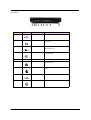
Rear Panel
#
12
Icon
Port
Description
1
Two USB ports
Connects USB 2.0 devices.
2
Modem jack
Connects the built-in fax/data modem to a
phone line.
3
S-video
Connects to a television or display device
with S-video input.
4
External display port
Connects an external (VGA) display
devices monitor.
5
COM port
Connects to other serial interface devices.
6
Network jack
Connects to an Ethernet 10/100/1000based network.
7
Parallel port
Connects a parallel device, such as a
printer.
8
PS2 port
Connects to a PS2 mouse.
9
Kensington lock slot
Attaches a security connector.
Aspire 1710
Bottom Panel
#
Item
Description
1
Battery cover
Protects the battery bay.
2
Sub-woofer
Enhances the audio quality
3
Ventilation slots
Enable the computer to stay cool, even after prolonged
use.
Chapter 1
13
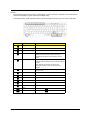
Indicators
The computer provides an array of five indicators located above the keyboard, in addition to two indicators
positioned at the top right hand corner of the LCD panel. These indicators show the status of the computer and
its components.
The five indicators located above the keyboard provide the following status information:
#
Icon
Function
Description
1
Hard Disk Drive Activity
Lights when the hard disk drive is active.
2
Battery Charge
Green--the AC adapter is connected and the
battery is fully charged.
Amber--the AC adapter is connected and the
battery is charging.
Off--the AC adapter is not connected, or the
battery is not installed.
14
3
Caps Lock Activity
Lights when Caps Lock is activated.
4
Num Lock Activity
Lights when Numeric Lock is activated.
5
Scroll Lock Activity
Lights when Numeric Lock key is activated.
Aspire 1710
The two indicators located at the front of the unit provide the following status information:
#
Icon
1
Function
Description
Power Mode
Steady green--the computer is on (even if the
display is turned off).
Steady orange--the computer is in standby
mode.
Off--the computer is turned off, or in the
hibernation mode.
2
InviLink Indicator
Indicates status of wireless or Bluetooth
(optional) communications.
Orange--WLAN
Blue--Bluetooth
Chapter 1
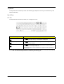
15
Keyboard
The keyboard has full-sized keys and an embedded keypad, separate cursor keys, two Windows keys and
twelve function keys.
Special keys
Lock keys
The keyboard has three lock keys which you can toggle on and off.
Lock key
Caps Lock
@
Num Lock (Fn-F11)
]
Scroll Lock (Fn-F12)
[
Description
When @is on, all alphabetic characters typed are in uppercase. Toggle on and
off by pressing the Caps Lock key on the left side of the keyboard.
When ] is on, the embedded numeric keypad can be used. Toggle on and off
by pressing the Num Lock Key.
When [ is on, the screen toggles up or down one line at a time when the up
and down cursor control keys are pressed.
Note: Scroll Lock doesn’t work in all applications. Toggle on and off by pressing the
Scroll Lock Key.
NOTE: If an external keyboard or keypad is connected to the computer, the Num Lock feature automatically
shifts from the internal keyboard to the external keyboard or keypad.
16
Aspire 1710
Windows keys
The keyboard has two keys that perform Windows-specific functions.
Keys
Windows logo key
Description
Start button. Combinations with this key perform shortcut functions. Below
are a few examples:
+ Tab (Activates next taskbar button)
+ E (Explores My Computer)
+ F (Finds Document)
+ M (Minimizes All)
j+
+ M (Undoes Minimize All)
+ R (Displays the Run... dialog box)
Application key
Chapter 1
This key has the same effect as clicking the right mouse button; it opens the
application’s context menu.
17
Hot Keys
The computer employs hot keys or key combinations to access most of the computer’s controls like screen
contrast and brightness, volume output and the BIOS Utility.
To activate hot keys, press and hold the Fn key before pressing the other key in the hot key combination.
Hot Key
Function
Description
Fn+l
Hotkey help
Displays a list of the hotkeys and their functions.
Fn+m
Device Manager
Accesses Windows Device Manager.
Fn-n
Power Scheme Toggle
Select suitable power scheme to the system.
Fn-o
Sleep
Puts the computer in Sleep Mode, which can be
defined via the advanced section of the Power
Management Properties in the Windows Control
Panel.
Fn-p
Display toggle
Switches display output between the system LCD, an
external monitor and both the sytem LCD and external
monitor.
Note: UMA sku should use Ctrl+Alt+F1 Intel
international hot key, when LCD monitor is hot
plugged.
18
Fn-q
Screen blank
Turns the LCD backlight off to save power; press any
key to resume.
Fn-r
Touchpad on/off
Turns the internal touchpad on and off.
Fn-s
Speaker on/off
Turns the speakers on and off; mutes the sound.
Fn-x
Brightness up
Increases the screen brightness.
Fn-¨z
Brightness down
Decreases the screen brightness.
Fn-w
Volume up
Increases the sound volume.
Fn-y
Volume down
Decreases the sound volume.
Fn-{
Home
Functions as the g key.
Fn-}
End
Functions as the d key.
Aspire 1710
Euro key
Your computer supports the new Euro currency character. First, hold down the Alt Gr key, and then press the
Euro key.
Keyboard ergonomics
The wide palm rest area provides a comfortable platform for your hands when typing on the keyboard. The
ergonomic design enables you to adopt a relaxed, yet very efficienct, typing style.
Chapter 1
19
Touchpad
The built-in touchpad is a PS/2 - compatible pointing device that senses movement on its surface. The cursor
responds to your finger movements on the touchpad. In addition, the two click buttons provide the same
functionality as a computer mouse, while the scroll key enables easy up and down scrolling in documents and
web pages.
The touchpad is located in the middle of the palm rest area, providing maximum comfort and effiency.
Touchpad basics
Use the touchpad as follows:
T
Slide your finger over the surface of the touchpad to control the movement of the cursor. Tap the
touchpad to perform selection and execution functions.
T
Press the left (1) and right (3) click buttons to perform selection and execution functions, just as
you would use the buttons on a computer mouse.
T
Use the scroll key (2) to scroll through long documents and web pages. Press the top of the key to
scroll up, and the bottom to scroll down.
Function
Right Button
Tap
Click twice quickly.
Tap twice quickly.
Select
Click one.
Tap once.
Drag
Click and hold. Then, slide
your finger across the
touchpad to drag the cursor
over the selection.
Tap twice quickly. On the
second tap, slide your finger
across the touchpad to drag
the cursor over the selection.
Access
content menu
20
Left Button
Execute
Click once.
Aspire 1710
Launch Keys
Located at the top of the keyboard are five buttons. These buttons are called launch keys. These buttons are
called launch keys. They are designated as key 1, key 2, key 3, key 4, key 5. By default, key 1 is used to
launch wireless LAN/Bluetooth, key 2 is to launch the E-mail application, and key 3 is used to launch the
internet browser. Keys 4 and 5 start the Launch Manager application. All five launch keys can be set by the
user. To set the launch keys, run the Acer Manager.
Launch key
Icon
Description
InviLink
Enable or disables wireless or Bluetooth
(optional) connectivity.
E-mail
Launch your E-mail application
Web browser
Launches your Internet browser.
P1
User-programmable
P2
User-programmable
Chapter 1
21
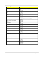
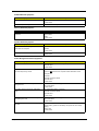
Hardware Specifications and Configurations
System Board MajorChips
Item
System core logic
Controller
Intel Desktop Pentium 4 Northwood/Prescott processor at 2.6GHz to
3.4GHz or higher; FSB 533/800MHz
865G+ICH5, support 533/800MHz FSB, dual channel and HTT support
Super I/O controller
NS PC87391
Audio controller
Realtek ALC202
Video controller
Internal: 865G + Chrontel CH7017
External: Nvidia GF-FX-GO5200 or FG-FX-GO5700
Hard disk drive controller
Embedded in Intel ICH5
Keyboard controller
NS LPC keyboard controller PC87591
CardBus Controller
ENE CB1410
RTC
Intel ICH5
Processor
Item
Specification
CPU type
Intel Desktop Pentium 4 Northwood/Prescott Processor at 2.6GHz to 3.4GHz
or higher
CPU package
To 3.40GHz mPGA-478
CPU core voltage
Base on processor speed/FSB/VCCID value
CPU I/O voltage
Base on processor speed/FSB/VCCID value
BIOS
Item
Specification
BIOS vendor
Phoenix BIOS
BIOS Version
3A02
BIOS ROM type
Flash ROM
BIOS ROM size
1024KB
BIOS package
32 Pin PLCC
Supported protocols
ACPI 2.0 (if available, at least 1.0b), SMBIOS 2.3, PCI 2.3 Boot Block, PXE
2.0, Mobile PC2001, Hard Disk Password, INT 13h Extensions, PCI Bus
Power Management interface Specification, EI Torito-Bootable CD-ROM
Format Specification V1.0, Simple Boot Flag 1.0
BIOS password control
Set by switch, see SW1 settings
Second Level Cache
Item
22
Specification
Cache controller
Built-in CPU
Cache size
1024KB
1st level cache control
Always Enabled
2nd level cache control
Always Enabled
Cache scheme control
Fixed-in write back
Aspire 1710
System Memory
Item
Specification
Memory controller
Intel 865G
Onboard memory size
0MB
DIMM socket number
2 Sockets
Supports maximum memory size per
socket
1024MB
Supports maximum memory size
2048MB
Supports DIMM type
DDR-DRAM
Supports DIMM Speed
266 MHz/333 MHz/400 MHz
Supports DIMM voltage
2.5 V
Supports DIMM package
184-pin Long-DIMM
Memory module combinations
You can install memory modules in any combinations as long as they
match the above specifications .
Memory Combinations
Slot 1
Slot 2
Total Memory
256MB
0MB
256MB
0MB
256MB
256MB
256MB
256MB
512MB
0MB
512MB
512MB
512MB
128MB
640MB
256MB
512MB
768MB
512MB
256MB
768MB
512MB
512MB
1024MB
0MB
512MB
512MB
1024MB
0MB
1024MB
1024MB
256MB
1280MB
1024MB
512MB
1536MB
0MB
1024MB
1024MB
256MB
1024MB
1280MB
512MB
1024MB
1536MB
Above table lists some system memory configurations. You may combine DIMMs with various capacities to
form other combinations.
LAN Interface
Item
Specification
Chipset
Broadcom BCM5788M
Supports LAN protocol
10/100/1000Mbps
LAN connector type
RJ45
LAN connector location
Rear side
Modem Interface
Item
Chipset
Chapter 1
Specification
Internal Agere Scorpio chipset (Scorpio+CSP1037B)
23
Modem Interface
Item
Specification
Fax modem data baud rate (bps)
14.4K
Data modem data baud rate (bps)
56K
Supports modem protocol
V.90/V.92MDC
Modem connector type
RJ11
Modem connector location
Rear side
Card Reader Interface
Item
Specification
Vendor & model name
Mitsumi D353G 4515
MCI JU-226A033FC
Floppy Disk Specifications
Media recognition
2DD (720KB)
2HD (1.2 MB, 3 mode)
2HD (1.44MB)
Sectors/track
9
15
18
Tracks
80
80
80
Data transfer rate
(Kbit/s)
1 MB
1.6 MB
2 MB
Rotational speed (RPM)
300
360
300
Read/write heads
2
Encoding method
MFM
Power Requirement
Input Voltage (V)
+5V
Hard Disk Drive Interface
Item
Specification
Vendor & Model Name
SEAGATE U9 ST380012A
Capacity (MB)
80000
Bytes per sector
512
Logical heads
16
Logical sectors
63
Drive Format
Logical cylinders
16383
Physical read/write heads
2
Disks
1
Spindle speed (RPM)
5400RPM
Performance Specifications
Buffer size
1MB
Interface
ATA-5
Data transfer, rate
(host~buffer, Mbytes/s)
100 MB/Sec
DC Power Requirements
Voltage tolerance (including
noise)
5 +/- 5%
12V +/-10%
Note: The drive receives DC power (5V or 12V)
through a four-pin standard drive power
connector
24
Aspire 1710
DVD-ROM Interface
Item
Specification
Vendor & model name
Pioneer DVR-K12RA
Performance Specification
With CD Diskette
With DVD Diskette
Transfer rate (KB/sec)
Average Sustained:
DVD-5:
CAV mode
Normal Speed (1X) 11.08 Mbits/sec
775~1800 blocks/sec
CAV mode 36.67~88.64 Mbits/sec
(10.3X to 24X)
DVD-9/DVD-R:
1550~3600kBytes/sec (Mode 1)
Normal Speed (1X) 11.08 Mbits/sec
1768~4106 kBytes/sec (Mode 2)
CAV mode 36.67~88.64 Mbits/sec
Random (*1)
DVD-5:
CAV mode 110 msec typical 150
msec average max
Random (*4)
120 msec typical
160 msec average max
Average Full Access time (typ.)
Full Stroke (*2)
CAV mode 200 msec typical 260
msec average max
Full Stroke (*5)
270 msec typical
350 msec average max
DVD-9:
Random (*7)
150 msec typical
200 msec average max
Full Stroke (*8)
340 msec typical
450 msec average max
DVD-RAM (2.6G)
Random (*7)
200 msec typical
300 msec average max
Full Stroke (*8)
300 msec typical
600 msec average max
DVD-RAM (4.7G)
Random (*9)
180 msec typical
300 msec average max
Full Stroke (*10)
320 msec typical
700 msec average max
Data Buffer Capacity
512 kBytes
Interface
IDE
Applicable disc format
DVD: DVD-5, DVD-9, DVD-10, DVD-R (3.95G), DVD-RAM (2.6G), DVDRAM (4.7G)
CD: CD-Audio, CD-ROM (mode 1 and mode 2), CD-ROM XA (mode 2, form
1 and form 2), CD-I (mode 2, form 1 and form 2), CD-I Ready, CD-I Bridge,
CD-WO, CD-RW, Photo CD, Video CD, Enhanced Music CD, CD-TEXT
Loading mechanism
Soft eject (with emergency eject hole)
Power Requirement
Input Voltage
+5V[DC]+/-5%
(*1) Average of Data read over the whole area from 00 min. 02 sec. 00 block to 59 min. 58 sec. 74 block more
than 2000 times including latency and layered error correction time.
(*2) From 00 min. 02 sec. 00 block to 59 min. 58 sec. 74 block including latency and layered error correction
time.
(*3) Disc: MNSU-005
Chapter 1
25
(*4) Average of Data read over the whole area from starting data recorded area (LBA:0) to maximum data
recorded area (LBA:23197F), more than 2000 times including latency and layered error correction time.
(*5) from starting data recorded area (LBA:0) to maximum data recorded area (LBA:23197F) including latency
and layered error correction time.
(*6) Disk: MKE-D551.
(*7) Average of Data read over the whole area from starting data recorded area (LBA:0) to maximum data
recorded area (LBA:3FA0DF), more than 2000 times including latency and layered error correction time.
(*8) from starting data recorded area (LBA:0) to maximum data recorded area (LBA:3FA0DF) including latency
and layered error correction time.
(*9) Disk: ODSC-PARA
Combo Drive Interface
Item
Vendor & model name
Specification
KME UJDA740
Performance Specification
Transfer rate (KB/sec)
Read Sustained:
DVD-ROM MAX 8X CAV (MAX 10800 KB/sec)
CD-ROM
MAX 24X CAV (MAX 3600 KB/sec)
CD-R
4X, 8X (CLV), Max 16X, MAX 24X (ZCLV)
Write:
CD-RW
4X (CLV)
HS-RW
4X,8X, 10X (CLV)
ATAPI Interface:
PIO mode 16.6 MB/sec :PIO Mode 4
DMA mode 16.6 MB/sec:Multi word mode 2
Ultra DMA mode 33.3MB/sec: Ultra DMA mode 2
Buffer rate
2MB
Access time
DVD-ROM 180 ms typ. (1/3 stroke)
Start up time
less than 15s
Stop time
less than 6s
Acoustic noise
less than 50 dBA
CD-ROM 130 ms typ. (1/3 stroke)
Interface
Enhanced IDE (ATAPI) compatible
Master/Slave
Set by Cable Select (By host)
PC compatible
PC2001 compatible
Applicable disc format
CD:
CD-DA, CD-ROM, CD-ROM XA, CD-R, CD-RW, PhotoCD (multiSession),
Video CD, CD-Extra(CD+), CD-text
DVD: DVD-ROM, DVD-R, DVD-RW (Ver.1.1)
Slope
15 degree (Any direction)
Dimensions, Weight
128X129X12.7mm (WXDXH)
(except protrusion)
200g+- 10g
Eject
Soft Eject (with emergency eject hole)
Audio Interface
Item
26
Specification
Audio Controller
Realtek ALC202
Audio onboard or optional
Built-in
Mono or Stereo
Stereo
Aspire 1710
Audio Interface
Item
Resolution
Specification
20 bit stereo Digital to Analog converter
18 bit stereo Analog to Digital converter
Compatibility
Microsoft PC98/PC99, AC97 2.2
Mixed sound source
Line-in, CD, Video, AUX
Voice channel
8/16 bit, mono/stereo
Sampling rate
44.1 KHz
Internal microphone
Yes
Internal speaker / Quantity
Yes
Supports PnP DMA channel
DMA channel 0
DMA channel 1
Supports PnP IRQ
IRQ10, IRQ11
Video Interface
Item
Specification
Vendor & Model Name
Intel 865G
Chip voltage
Core / 2.5V, 1.5V,
Supports ZV (Zoomed Video) port
NO
Graph interface
8X AGP (Accelerated Graphic Port) Bus
Maximum resolution (LCD)
1024 x768 (32bit colors)
Maximum resolution (CRT)
1024x768 (32 bit colors)
1280x1024 (32 bit colors)
1600x1200 (32 bit colors)
Video Memory
Item
Specification
Fixed or upgradeable
Fixed, share the system memory
Video memory size
32MB
Parallel Port
Item
Specification
Parallel port controller
NS PC87391
Number of parallel port
1
Location
Rear side
Connector type
25-pin D-type
Parallel port function control
Enable/Disable by BIOS Setup
Supports ECP/EPP
Yes (set by BIOS setup)
Optional ECP DMA channel
(in BIOS Setup)
DMA channel 1 and 3
Optional parallel port I/O address
(in BIOS Setup)
378, 278, 3BC
Optional parallel port IRQ
(in BIOS Setup)
IRQ7, IRQ5
Chapter 1
27
USB Port
Item
Specification
USB Compliancy Level
2.0
OHCI
USB 2.0
Number of USB port
4
Location
Rear side
Serial port function control
Enable/Disable by BIOS Setup
PCMCIA Port
Item
Specification
PCMCIA controller
ENE CB1410
Supports card type
Type II, Tpye III
Number of slots
Two type II, one type III
Access location
Left side
Supports ZV (Zoomed Video) port
Yes
Supports 32 bit CardBus
Yes (IRQ17)
Keyboard
Item
Specification
Keyboard controller
NS LPC keyboard controller PC87591
Keyboard vendor & model name
Sunrex
Total number of keypads
103- key
Windows 95 keys
Yes
Internal & external keyboard work simultaneously
Yes
Battery
Item
Specification
Vendor & model name
SIMPLO
Battery Type
Li-ION
Pack capacity
6600mAH
Cell voltage
3.8V
Number of battery cell
12
Package configuration
4S3P
Package voltage
14.4V
DC-AC LCD Inverter
Item
Vendor & model name
28
Specification
Ambit
Input voltage (V)
10 ~ 20V
Input current (mA)
1A (max.)
Output voltage
725Vrms
Output voltage frequency (kHz)
40 ~ 65Hz
Output Current
1.5 mArms ~ 3.75mArms
Aspire 1710
.
LCD
Item
Specification
Vendor & model name
QDI (Quanta Display Inc.)
QD17EL07
Mechanical Specifications
LCD display area (diagonal, inch)
17”
Active area
337.9mmX270.3mm
Display technology
TFT
Resolution
SXGA (1280X1024)
Support colors
262K
Optical Specification
Brightness control
Keyboard hotkey
Contrast ratio
300(min.)/450(typ.)
Response time
16ms
Luminance of white (cd/m )
220(typ.)/270(max.)
White Uniformity
1.25(typ.)/1.33(max.)
Contrast control
None
2
Electrical Specification
Supply voltage for LCD display (V)
5 (typ.)
Supply voltage for LCD backlight (Vrms)
725 (typ.)
AC Adapter
Item
Vendor & model name
Specification
DELTA ADP-180W PFC
Input Requirements
Nominal voltage
100-240Vac input AC voltage
Maximum input current
2.5A Max. at 180W load and 100Vac input voltage.
Rated frequency (Hz)
50 or 60
Frequency variation range (Hz)
47-63
Input voltage range
90-264Vac
Inrush current limit (cold start)
100A max. at 115Vac and 200A max. at 240Vac
Efficiency
84% min. at normal (Min) input voltage, maximum load and measured at the
end of DC cable.
Output Ratings (CV mode)
DC output voltage
19V
Noise + Ripple
400mV
Load
0(min) 3.16A(max)
Output Ratings (CC mode)
DC output voltage range
18.05-19.95V when the load is 0A-9.5A
Dynamic Output Characteristics
Switch-on delay time
3 sec (at maximum load and nominal voltage input)
Hold up time
6ms within regulation requirement after loss nominal input voltage and
maximum load (180W)
Over Voltage Protection (OVP)
25V
Electrostatic discharge (ESD)
15KV (at air discharge)
8KV (at contact discharge)
Dielectric Withstand Voltage
Chapter 1
29
AC Adapter
Item
Specification
Primary to secondary
3000Vac
Leakage current
0.25 mA max. (@ 254Vac, 60Hz)
Power Management
Power Saving Mode
Standby Mode
Enter Standby Mode when
Phenomenon
T
T
The buzzer beeps
The Sleep indicator lights up
T
All power shuts off
T
The display shuts off
T
Hard disk drive is in standby mode.
(spindle turned-off)
1.Standby/Hibernation hot-key is pressed
and system is not ready to enter Hibernation
mode.
2.System standby/ Hibernation timer expires
and system is not ready to enter Hibernation
mode.
Hibernation Mode
Enter Hibernation Mode (suspend to HDD)
when
1.Hibernation hot-key is pressed and
system is ready to enter Hibernation mode
2.System Hibernation timer expires and
system is ready to enter Hibernation mode.
Display Standby Mode
Keyboard, built-in touchpad, and an external
PS/2 pointing device are idle for a specified
period.
Hard Disk Standby Mode
Hard disk is idle within a specified period of
time.
30
Aspire 1710
Chapter 1
31
Chapter 2
System Utilities
BIOS Setup Utility
The BIOS Setup Utility is a hardware configuration program built into your computer’s BIOS (Basic Input/
Output System).
Your computer is already properly configured and optimized, and you do not need to run this utility. However, if
you encounter configuration problems, you may need to run Setup. Please also refer to Chapter 4
Troubleshooting when problem arises.
To activate the BIOS Utility, press m during POST (when “Press <F2> to enter Setup” message is prompted
on the bottom of screen).
Press m to enter setup. Press <F12> during POST to enter multi-boot menu. In this menu, user can change
boot device without entering BIOS SETUP Utility.
Chapter 2
32
Navigating the BIOS Utility
There are six menu options: Info., Main, System Devices, Security, Boot, and Exit.
Follow these instructions:
T
To choose a menu, use the cursor left/right keys (zx).
T
To choose a parameter, use the cursor up/down keys ( wy).
T
To change the value of a parameter, press por q.
T
A plus sign (+) indicates the item has sub-items. Press e to expand this item.
T
Press ^ while you are in any of the menu options to go to the Exit menu.
T
In any menu, you can load default settings by pressing t. You can also press u to save any
changes made and exit the BIOS Setup Utility.
NOTE: You can change the value of a parameter if it is enclosed in square brackets. Navigation keys for a
particular menu are shown on the bottom of the screen. Help for parameters are found in the Item
Specific Help part of the screen. Read this carefully when making changes to parameter values.
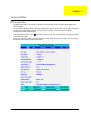
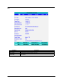
This menu provides you the information of the system.
33
Aspire 1710
Info.
Parameter
Description
Floppy Disk Drive
Shows floppy drive type informaiton.
Serial Number
This field displays the serial number of this unit.
UUID Number
UUID=32bytes
Chapter 2
34
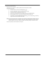
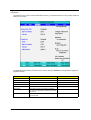
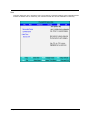
Main
The Main screen displays a summary of your computer hardware information, and also includes basic setup
parameters. It allows the user to specify standard IBM PC AT system parameters.
NOTE: The screen above is for reference only. Actual values may differ.
35
Aspire 1710
The table below describes the parameters in this screen. Settings in boldface are the default and suggested
parameter settings.
Parameter
Description
Format/Option
System Time
Sets the system time.
Format: HH:MM:SS
(hour:minute:second) System Time
System Date
Sets the system date.
Format MM/DD/YYYY (month/day/
year)
System Date
System Memory
This field reports the memory size of the system.
Memory size is fixed to 640MB
Extended Memory
This field reports the memory size of the
extended memory in the system.
Extended Memory size=Total memory size-1MB
Video Memory
Shows the VGA memory size.
Fast Boot
Determines if Customer Logo will be displayed or
not; shows Summary Screen is disabled or
enabled.
Option: Enabled or Disabled
Enabled: Customer Logo is displayed, and
Summary Screen is disabled.
Disabled: Customer Logo is not displayed, and
Summary Screen is enabled.
Power on display
Auto: During power process, the system will
detect if any display device is connected on
external video port. If any external display device
is connected, the power on display will be in CRT
(or projector) only mode. Otherwise it will be in
LCD only mode.
Option: Auto or Both
Both: Simultaneously enable both the integrated
LCD screen and the system’s external video port
(for an external CRT or projector).
LCD Auto Dim
Determines if the system will automatically dim
the LCD brightness in order to save power when
AC is not present.
Option: Enabled or Disabled
F12 Boot Menu
Enables, disables Boot Menu during POST.
Option: Disabled or Enabled
NOTE: The sub-items under each device will not be shown if the device control is set to disable or auto. This is
because the user is not allowed to control the settings in these cases.
Chapter 2
36
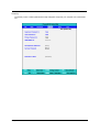
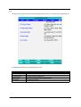
Advanced
The Advanced menu screen contains parameters involving your hardware devices. It also provides advanced
settings of the system.
The table below describes the parameters in the screen. Settings in boldface are the default and suggested
parameter settings.
Parameter
37
Description
Options
Infrared Port
Enables, disables or auto detects the infrared port.
Disabled/Disabled/Auto
Parallel Port
Enables, disables or auto detects the parallel port.
Enabled/Disabled/Auto
Mode
Sets the operation mode of the parallel port.
ECP, EPP, Normal or Bi-directional
Base I/O address
Sets the I/O address of the parallel port.
378h/278h/3BCH
Interrupt
Sets the interrupt request of the parallel port.
IRQ7/IRQ5
DMA channel
Sets a DMA channel for the printer to operate in
ECP mode. This parameter is enabled only if Mode
is set to ECP.
DMA3/DMA1
Legacy USB Support
Enables, disables USB interface devices support
under DOS mode.
Option: Disabled or Enabled
Aspire 1710
Security
The Security screen contains parameters that help safeguard and protect your computer from unauthorized
use.
Chapter 2
38
The table below describes the parameters in this screen. Settings in boldface are the default and suggested
parameter settings.
Parameter
Description
Option
User Password is
Shows the setting of the user password.
Clear or Set
Supervisor Password is
Shows the setting of the Supervisor password
Clear or Set
Set User Password
Press Enter to set the user password. When
set, this password protects the BIOS Setup
Utility from unauthorized access.
Set Supervisor Password
Press Enter to set the supervisor password.
When set, this password protects the BIOS
Setup Utility from unauthorized access.
Primary Harddisk Security
This feature is available to user when
Supervisor password is set. Password can be
written on HDD only when Supervisor
password or user password is set and
password on HDD is set to enabled.
Supervisor Password is written to HDD only
when Supervisor password is being set. User
password is written to HDD when both
passwords are set. When both Supervisor and
user password are present, both passwords
can unlock the HDD.
Disabled or Enabled
Password on Boot
Defines whether a password is required or not
while the events defined in this group
happened. The following sub-options are all
requires the Supervisor password for changes
and should be grayed out if the user password
was used to enter setup.
Disabled or Enabled
NOTE: When you are prompted to enter a password, you have three tries before the system halts. Don’t forget
your password. If you forget your password, you may have to return your notebook computer to your
dealer to reset it.
Setting a Password
Follow these steps as you set the user or the supervisor password:
1.
Use the w andy keys to highlight the Set Supervisor Password parameter and press the e key. The
Set Supervisor Password box appears:
2.
Type a password in the “Enter New Password” field. The password length can not exceeds 8
alphanumeric characters (A-Z, a-z, 0-9, not case sensitive). Retype the password in the “Confirm New
Password” field.
IMPORTANT:Be very careful when typing your password because the characters do not appear on the screen.
3.
39
4.
Press e.
After setting the password, the computer sets the User Password parameter to “Set”.
If desired, you can opt to enable the Password on boot parameter.
5.
When you are done, press u to save the changes and exit the BIOS Setup Utility.
Aspire 1710
Removing a Password
Follow these steps:
1.
Use the w and y keys to highlight the Set Supervisor Password parameter and press the e key. The
Set Password box appears:
2.
Type the current password in the Enter Current Password field and press e.
3.
Press e twice without typing anything in the Enter New Password and Confirm New Password fields.
The computer then sets the Supervisor Password parameter to “Clear”.
4.
When you have changed the settings, press u to save the changes and exit the BIOS Setup Utility.
Changing a Password
1.
Use the w and y keys to highlight the Set Supervisor Password parameter and press the e key. The
Set Password box appears:
2.
Type the current password in the Enter Current Password field and press e.
3.
Type a password in the Enter New Password field. Retype the password in the Confirm New Password
field.
4.
Press e. After setting the password, the computer sets the User Password parameter to “Set”.
5.
If desired, you can enable the Password on boot parameter.
6.
When you are done, press u to save the changes and exit the BIOS Setup Utility.
If the verification is OK, the screen will display as following.
The password setting is complete after the user presses u.
Chapter 2
40
If the current password entered does not match the actual current password, the screen will show you the
Setup Warning.
If the new password and confirm new password strings do not match, the screen will display the following
message.
41
Aspire 1710
Boot
This menu allows the user to decide the order of boot devices to load the operating system. Bootable devices
includes the distette drive in module bay, the onboard hard disk drive and the CD-ROM in module bay.
Chapter 2
42
Exit
The Exit screen contains parameters that help safeguard and protect your computer from unauthorized use.
The table below describes the parameters in this screen.
Parameter
Exit Saving Changes
43
Description
Exit System Setup and save your changes to CMOS.
Exit Discarding Changes
Exit utility without saving setup data to CMOS.
Load Setup Default
Load default values for all SETUP item.
Discard Changes
Load previous values from CMOS for all SETUP items.
Save Changes
Save Setup Data to CMOS.
Aspire 1710
BIOS Flash Utility
The BIOS flash memory update is required for the following conditions:
T
New versions of system programs
T
New features or options
T
Restore a BIOS when it becomes corrupted.
Use the Phlash utility to update the system BIOS flash ROM.
NOTE: If you do not have a crisis recovery diskette at hand, then you should create a Crisis Recovery
Diskette before you use the Phlash utility.
NOTE: Do not install memory-related drivers (XMS, EMS, DPMI) when you use the Phlash.
NOTE: Please use the AC adaptor power supply when you run the Phlash utility. If the battery pack does not
contain enough power to finish BIOS flash, you may not boot the system because the BIOS is not
completely loaded.
Fellow the steps below to run the Phlash.
1.
Prepare a bootable diskette.
2.
Copy the Phlash utilities to the bootable diskette.
3.
Then boot the system from the bootable diskette. The Phlash utility has auto-execution function.
Chapter 2
44
45
Aspire 1710
Chapter 3
Machine Disassembly and Replacement
This chapter contains step-by-step procedures on how to disassemble the notebook computer for
maintenance and troubleshooting. To disassemble the computer, you need the following tools:
T
An ESD mat
T
A Philips screw driver
T
A tweezers
Hex screw driver
NOTE: Use an ESD wristband to avoid the risk of electronic discharge
T
Chapter 3
46
General Information
Before You Begin
Before proceeding with the disassembly procedure, make sure that you do the following:
47
1.
Turn off the power to the system and all peripherals.
2.
Unplug the AC adapter and all power and signal cables from the system.
3.
Jewelry such as watches, rings and bracelets should be removed before service disassembly.
Aspire 1710
Disassembly Procedure Flowchart
The flowchart on the succeeding page gives you a graphic representation on the entire disassembly sequence
and instructs you on the components that need to be removed during servicing. For example, if you want to
remove the system board, you must first remove the keyboard, then disassemble the inside assembly frame in
that order.
Start
x7 (fix on base cover)
Base Cover
Dx4
Cx1
Battery
Dommy Cover
Battery
Cx2
MDC Modem
Card
Cx1
Optical Drive
Module
(Please see
next page)
Memory
Disconnect
subwoofer cable
Subwoofer
Thermal
Module (FAN
Sink) w/
screws *4pcs
HDD Module
Disconnect HDD
power cable and
IDE coaxial cable
Rx4
HDD Bracket
Cx3
Inverter Cover
Jx4
Cx2
Cx4
x2
Cx4
VGA Card
(AGP Card)
Hinge Cover
Wireless Card
x6
x4
Upper System
Cover (Middle
Cover)
CPU
x4 on rear
HDD
Disconnect LED cable
x4
LCD Module
LCD Outer
Shield (LCD
panel)
LED Cable
Remove inverter board mylar
Inverter Board
Brackets
LCD Cable
Chapter 3
x2
Inverter Board
Side Brackets
(LCD
Brackets)
LCD
Ux8
Wireless
Antenna
Keyboard
Dx6
Silicon Line Pad
(LCD Decoration
Bar)
Dx8
Bx2
LCD Skirting
Board (LCD
Bezel)
Ox4
LED Board
(Launch
Board)
LED Cable
Disconnect touchpad FFC
Px1
Qx2
Kx5
Mx2
Tx6
Jx4
Dx8
See Next
Page
Bx4
48
Con't
Front Panel
(Upper Case
Assy)
Base Assy
x2
Cx3
FDD Module
Audio DJ
Board Cable
Speaker
Cx8
Ox2
Main Board
Module
Base
Ix6
Cx2
Ox4
Touchpad
Switch Board
PCI Board
Cx2
Main Board w/
Fan
x1
Lid Switch
Cable
Touchpad
Bracket
Touchpad
I/O Shield
Ox1
Audio DJ
Board
FDD Module
Main Board
FDD FFC
Main Board
Bracket
Fan
Bx3
FDD Bracket
FDD
Optical Drive
Module
Ex3
Optical
Bracket
49
ODD
Aspire 1710
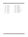
Screw List
Item
Description
B
SCREW MM25025ICI0
C
SCREW MM25040IL60
D
SCREW MM25060IL69
E
SCREW MM20030ICI3
F
SCREW MM20080ICI6
G
SCREW MM20100ICI3
H
SCREW MS17025B202
I
SCREW MBEA1001012
J
SCREW MF30060PBJ5
K
SCREW MM25070ICI5
L
SCREW MS25060ILR1
M
SCREW MS25060P527
O
SCREW MS25025IBX8
P
SCREW MS25180I100
Q
SCREW MS25100B371
R
SCREW MS0601BILQ1
T
SCREW MS25060IM01
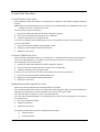
U
SCREW MM30050ICI4
Chapter 3
50
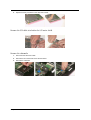
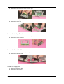
Disassembling
Remove the battery
1.
Release the seven screws as shown here.
2.
Remove the bottom shield plate.
3.
Remove the 5 screws as shown here.
4.
Remove the battery or dummy battery module.
Remove the HDD module
1.
Remove the 4 screws that secure the HDD module.
2.
Lift the HDD module and detach the IDE connector and power connector at the same time.
Remove the combo drive
51
1.
Remove the one screw as shown here.
2.
Detach the Combo drive.
Aspire 1710
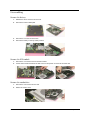
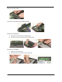
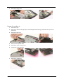
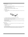
Remove the thermal module
1.
Disconnect the fan power connector.
1.
Remove the three screws as shown here.
2.
Remove the thermal module.
Remove CPU
1.
Open the CPU lever, remove the CPU and close the lever.
Remove the memory
1.
Remove the memory
Remove VGA card
1.
Disconnect the VGA connector.
2.
Release the four screws that secure the VGA card.
3.
Remove the VGA card.
Chapter 3
52
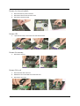
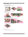
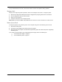
Detach the wireless card
1.
Detach the wireless card.
2.
Disconnect the two wireless cables.
Remove moden card
1.
Remove the screws on the MDC (modem card)
2.
Detach the card from the modem cable.
3.
Release the cable
Remove the inverter cover
53
1.
Remove the screws as shown here.
2.
Remove the inverter cover.
Aspire 1710
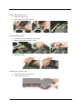
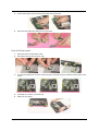
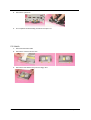
Detach the upper system cover
1.
Remove the two screws on the one side, and the two screws on the other. .
2.
Remove the hinge covers on each side
3.
Detach the upper system cover (middle cover).
Remove the LCD module
1.
Detach the LED cable from the LED board.
2.
Remove the screws that secure the hinge. And the other side.
3.
Detach the LCD panel from the main unit and place the panel by turning 180 degrees.
4.
Release the cables by following the instructions here carefully.
Chapter 3
54
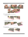
Remove the LCD panel
1.
Detach the silicon line pad by following the instruction here. And the other side.
2.
Unscrew the three screws on the edge of the LCD panel on both sides.
3.
Detach the LCD skirting board (LCD bezel) by following the instruction here.
4.
Remove the TEN screws on the side mount.
5.
Remove the LCD panel.
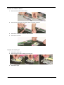
Remove the inverter board
1.
55
Remove the tape and disconnect the inverter cable.
Aspire 1710
2.
Follow the same procedure on the other inverter cable.
3.
Disconnect the inverter power cable from the inverter board.
4.
Remove the mylar that covering the inverter board.
5.
Remove the two screws that secure the inverter board bracket.
Chapter 3
56
Remove the mylars
Remove the wireless module
1.
Remove the two screws that secure the wireless antenna.
2.
Remove the antenna.
3.
Repeat the same procedure on the other side.
4.
Remove the wireless module.
Remove the side bracket
1.
57
Remove the two screws as shown here. Then remove the side bracket.
Aspire 1710
2.
Repeat the same procedure on the other side bracket.
Remove the LED cable attached on the LCD outer shield.
Remove the subwoofer
1.
Disconnect the subwoofer cable.
2.
Remove the two screws that secure the subwoofer.
3.
Remove the subwoofer.
Chapter 3
58
Release the MDC cable.
Disconnect the cable to the modem header.
Remove the keyboard
1.
Remove the six screws the secure the keyboard.
2.
Remove the keyboard and disconnect the attached cable.
Remove the LED board
59
1.
Detach the LED ribbon cable.
2.
Remove the four screws that secure the LED board.
Aspire 1710
3.
Lift the LED board and disconnect the LED cable at the same time.
4.
Disconnect the LED ribbon cable from the LED board.
Detach the front panel
1.
Disconnect the touch pad ribbon cable.
2.
Remove the three screws as shown here.
3.
Turn the unit upside down, and then remove the group of FOUR, the group of EIGHT and the group of SIX
screws.
4.
And finally the 4 screws on the rear side.
5.
Detach the front panel.
Chapter 3
60
Remove the Audio DJ board
1.
Disconnect the Audio DJ ribbon cable.
2.
Disconnect the other side of the ribbon cable to the Audio DJ board.
3.
Remove the screw that secures the Audio DJ board.
4.
Remove the DJ board.
Remove the touch pad
61
1.
Remove the mylar here.
2.
Disconnect the two ribbon cables to the touch pad.
3.
Remove the mylar.
Aspire 1710
4.
Remove the two screws that secure the touch pad.
5.
Remove the touch pad bracket.
6.
Remove the touch pad.
Remove the touch pad board
1.
Remove the four screws that secure the touch pad board.
2.
Remove the touch pad board.
Remove the lid switch cable
1.
Disconnect the lid switch cable by releasing the screw.
2.
Remove the lid switch cable.
Remove the floppy drive
1.
Disconnect the floppy cable
2.
Remove the three screws
Chapter 3
62
3.
Remove the floppy drive.
Remove the speaker set
63
1.
Remove the tape
2.
Remove the aluminum tape (the tape can be damaged while servicing, please make sure you have a
spare one).
3.
Remove the tape here.
4.
Disconnect the speaker cable.
5.
Remove the screw as shown here.
6.
And the one on the other side.
7.
Remove the speaker set.
Aspire 1710
Remove the mainboard
1.
Remove the nine screws as shown
2.
Detach the mainboard module from the base unit
3.
Remove the screw as shown
4.
Remove the PCI board.
5.
Remove the six screws that secure the I/O shield.
6.
Remove the I/O shield.
7.
Disconnect the system fan power connector.
8.
Remove the two screws, one on each side, that secure the mainboard.
9.
Remove the mainboard from the mainboard bracket.
Remove the system fan
1.
Remove the two screws that secure the system fan.
Chapter 3
64
2.
Remove the system fan.
3.
This completes the disassembly procedures of Aspire 1710.
FDD Module
65
1.
Disconnect the ribbon cable.
2.
Remove the screws as shown here.
3.
Remove the FDD bracket away from the floppy drive.
Aspire 1710
HDD Module
1.
Disconnect the HDD power cable and then the IDE coaxial cable.
2.
Remove the screws that secure the HDD, and the other side.
3.
Remove the bracket from the HDD.
Combo Module
1.
Remove the three screws as shown here.
2.
Remove the bracket.
Chapter 3
66
67
Aspire 1710
Chapter 4
Troubleshooting
Use the following procedure as a guide for computer problems.
NOTE: The diagnostic tests are intended to test only Acer products. Non-Acer products, prototype cards, or
modified options can give false errors and invalid system responses.
1.
Obtain the failing symptoms in as much detail as possible.
2.
Verify the symptoms by attempting to re-create the failure by running the diagnostic test or by repeating
the same operation.
3.
Use the following table with the verified symptom to determine which page to go to.
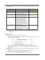
Symptoms (Verified)
Go To
Power failure. (The power indicator does not go
on or stay on.)
“Power System Check” on page 70.
POST does not complete. No beep or error
codes are indicated.
“Power-On Self-Test (POST) Error Message” on
page 73.
“Undetermined Problems” on page 81.
POST detects an error and displayed messages
on screen.
“Error Message List” on page 74.
Other symptoms (i.e. LCD display problems or
others).
“Power-On Self-Test (POST) Error Message” on
page 73.
Symptoms cannot be re-created (intermittent
problems).
Use the customer-reported symptoms and go to
“Power-On Self-Test (POST) Error Message” on
page 73.
“Intermittent Problems” on page 80.
“Undetermined Problems” on page 81.
Chapter 4
68
System Check Procedures
External Diskette Drive Check
Do the following to isolate the problem to a controller, driver, or diskette. A write-enabled, diagnostic diskette is
required.
NOTE: Make sure that the diskette does not have more than one label attached to it. Multiple labels can cause
damage to the drive or cause the drive to fail.
Do the following to select the test device.
1.
Boot from the diagnostics diskette and start the diagnostics program.
2.
See if FDD Test is passed as the program runs to FDD Test.
3.
Follow the instructions in the message window.
If an error occurs with the internal diskette drive, reconnect the diskette connector on the system board.
If the error still remains:
1.
Reconnect the external diskette drive/DVD-ROM module.
2.
Replace the external diskette drive/CD-ROM module.
3.
Replace the main board.
External CD-ROM Drive Check
Do the following to isolate the problem to a controller, drive, or CD-ROM. Make sure that the CD-ROM does
not have any label attached to it. The label can cause damage to the drive or can cause the drive to fail.
Do the following to select the test device:
1.
Boot from the diagnostics diskette and start the diagnostics program.
2.
See if CD-ROM Test is passed when the program runs to CD-ROM Test.
3.
Follow the instructions in the message window.
If an error occurs, reconnect the connector on the System board. If the error still remains:
1.
Reconnect the external diskette drive/CD-ROM module.
2.
Replace the external diskette drive/CD-ROM module.
3.
Replace the main board.
Keyboard or Auxiliary Input Device Check
Remove the external keyboard if the internal keyboard is to be tested.
If the internal keyboard does not work or an unexpected character appears, make sure that the flexible cable
extending from the keyboard is correctly seated in the connector on the system board.
If the keyboard cable connection is correct, run the Keyboard Test.
If the tests detect a keyboard problem, do the following one at a time to correct the problem. Do not replace a
non-defective FRU:
1.
Reconnect the keyboard cables.
2.
Replace the keyboard.
3.
Replace the main board.
The following auxiliary input devices are supported by this computer:
69
T
Numeric keypad
T
External keyboard
Aspire 1710
If any of these devices do not work, reconnect the cable connector and repeat the failing operation.
Memory check
Memory errors might stop system operations, show error messages on the screen, or hang the system.
1.
Boot from the diagnostics diskette and start the doagmpstotics program (please refer to main board.
2.
Go to the diagnostic memory in the test items.
3.
Press F2 in the test items.
4. Follow the instructions in the message window.
NOTE: Make sure that the DIMM is fully installed into the connector. A loose connection can cause an error.
Power System Check
To verify the symptom of the problem, power on the computer using each of the following power sources:
1.
Remove the battery pack.
2.
Connect the power adapter and check that power is supplied.
3.
Disconnect the power adapter and install the charged battery pack; then check that power is supplied by
the battery pack.
If you suspect a power problem, see the appropriate power supply check in the following list:
Chapter 4
T
“Check the Power Adapter” on page 71.
T
“Check the Battery Pack” on page 72.
70
Check the Power Adapter
Unplug the power adapter cable from the computer and measure the output voltage at the plug of the power
adapter cable. See the following figure
Pin 1: +19 to +20.5V
Pin 2: 0V, Ground
1.
If the voltage is not correct, replace the power adapter.
2.
If the voltage is within the range, do the following:
T
Replace the System board.
T
If the problem is not corrected, see “Undetermined Problems” on page 81.
T
If the voltage is not correct, go to the next step.
NOTE: An audible noise from the power adapter does not always indicate a defect.
71
3.
If the power-on indicator does not light up, check the power cord of the power adapter for correct
continuity and installation.
4.
If the operational charge does not work, see “Check the Battery Pack” on page 72.
Aspire 1710
Check the Battery Pack
To check the battery pack, do the following:
From Software:
1.
Check out the Power Management in control Panel
2.
In Power Meter, confirm that if the parameters shown in the screen for Current Power Source and Total
Battery Power Remaining are correct.
3.
Repeat the steps 1 and 2, for both battery and adapter.
4.
This helps you identify first the problem is on recharging or discharging.
From Hardware:
1.
Power off the computer.
2.
Remove the battery pack and measure the voltage between battery terminals 1(+) and 6(ground). See the
following figure
3.
If the voltage is still less than 7.5 Vdc after recharging, replace the battery.
To check the battery charge operation, use a discharged battery pack or a battery pack that has less than 50%
of the total power remaining when installed in the computer.
If the battery status indicator does not light up, remove the battery pack and let it return to room temperature.
Re-install the battery pack.
If the charge indicator still does not light up, replace the battery pack. If the charge indicator still does not light
up, replace the DC/DC charger board.
Touchpad Check
If the touchpad doesn’t work, do the following actions one at a time to correct the problem. Do not replace a
non-defective FRU:
1.
Reconnect the touchpad cables.
2.
Replace the touchpad.
3.
Replace the system board.
After you use the touchpad, the pointer drifts on the screen for a short time. This self-acting pointer movement
can occur when a slight, steady pressure is applied to the touchpad pointer. This symptom is not a hardware
problem. No service actions are necessary if the pointer movement stops in a short period of time.
Chapter 4
72
Power-On Self-Test (POST) Error Message
The POST error message index lists the error message and their possible causes. The most likely cause is
listed first.
NOTE: Perform the FRU replacement or actions in the sequence shown in FRU/Action column, if the FRU
replacement does not solve the problem, put the original part back in the computer. Do not replace a
non-defective FRU.
This index can also help you determine the next possible FRU to be replaced when servicing a computer.
If the symptom is not listed, see “Undetermined Problems” on page 81.
The following lists the error messages that the BIOS displays on the screen and the error symptoms classified
by function.
NOTE: Most of the error messages occur during POST. Some of them display information about a hardware
device, e.g., the amount of memory installed. Others may indicate a problem with a device, such as the
way it has been configured.
NOTE: If the system fails after you make changes in the BIOS Setup Utility menus, reset the computer, enter
Setup and install Setup defaults or correct the error.
73
Aspire 1710
Index of Error Messages
Error Code List
Error Codes
006
Error Messages
Equipment Configuration Error
Causes:
1. CPU BIOS Update Code Mismatch
2. IDE Primary Channel Master Drive Error
(THe causes will be shown before “Equipment Configuration
Error”)
010
Memory Error at xxxx:xxxx:xxxxh (R:xxxxh, W:xxxxh)
070
Real Time Clock Error
071
CMOS Battery Bad
072
CMOS Checksum Error
110
System disabled.
Incorrect password is specified.
<No error code>
Battery critical LOW
In this situation BIOS will issue 4 short beeps then shut down
system, no message will show.
<No error code>
Thermal critical High
In this situation BIOS will shut down system, not show message.
Error Message List
Error Messages
Failure Fixed Disk
FRU/Action in Sequence
Reconnect hard disk drive connector.
“Load Default Settings” in BIOS Setup Utility.
Hard disk drive
System board
Stuck Key
see “Keyboard or Auxiliary Input Device Check” on page 69.
Keyboard error
see “Keyboard or Auxiliary Input Device Check” on page 69.
Keyboard Controller Failed
see “Keyboard or Auxiliary Input Device Check” on page 69.
Keyboard locked - Unlock key switch
Unlock external keyboard
Monitor type does not match CMOS - Run Setup
Run “Load Default Settings” in BIOS Setup Utility.
Shadow RAM Failed at offset: nnnn
BIOS ROM
System board
System RAM Failed at offset: nnnn
DIMM
System board
Extended RAM Failed at offset: nnnn
DIMM
System battery is dead - Replace and run Setup
Replace RTC battery and Run BIOS Setup Utility to reconfigure
system time, then reboot system.
System CMOS checksum bad - Default
configuration used
RTC battery
System timer error
RTC battery
System board
Run BIOS Setup Utility to reconfigure system time, then reboot
system.
Run BIOS Setup Utility to reconfigure system time, then reboot
system.
System board
Chapter 4
74
Error Message List
Error Messages
Real time clock error
FRU/Action in Sequence
RTC battery
Run BIOS Setup Utility to reconfigure system time, then reboot
system.
System board
Previous boot incomplete - Default configuration
used
Run “Load Default Settings” in BIOS Setup Utility.
RTC battery
System board
Memory size found by POST differed from
CMOS
Run “Load Default Settings” in BIOS Setup Utility.
DIMM
System board
Diskette drive A error
Check the drive is defined with the proper diskette type in BIOS
Setup Utility
See “External Diskette Drive Check” on page 69.
Incorrect Drive A type - run SETUP
Check the drive is defined with the proper diskette type in BIOS
Setup Utility
System cache error - Cache disabled
System board
CPU ID:
System board
DMA Test Failed
DIMM
System board
Software NMI Failed
DIMM
System board
Fail-Safe Timer NMI Failed
DIMM
System board
Device Address Conflict
Run “Load Default Settings” in BIOS Setup Utility.
RTC battery
System board
Allocation Error for device
Run “Load Default Settings” in BIOS Setup Utility.
RTC battery
System board
Failing Bits: nnnn
DIMM
BIOS ROM
System board
Fixed Disk n
None
Invalid System Configuration Data
BIOS ROM
System board
I/O device IRQ conflict
Run “Load Default Settings” in BIOS Setup Utility.
RTC battery
System board
Operating system not found
Enter Setup and see if fixed disk and drive A: are properly identified.
Diskette drive
Hard disk drive
System board
75
Aspire 1710
Error Message List
No beep Error Messages
No beep, power-on indicator turns off and LCD is
blank.
FRU/Action in Sequence
Power source (battery pack and power adapter). See “Power
System Check” on page 70.
Ensure every connector is connected tightly and correctly.
Reconnect the DIMM.
LED board.
System board.
No beep, power-on indicator turns on and LCD is
blank.
Power source (battery pack and power adapter). See “Power
System Check” on page 70.
Reconnect the LCD connector
Hard disk drive
LCD inverter ID
LCD cable
LCD Inverter
LCD
System board
No beep, power-on indicator turns on and LCD is
blank. But you can see POST on an external
CRT.
Reconnect the LCD connectors.
LCD inverter ID
LCD cable
LCD inverter
LCD
System board
No beep, power-on indicator turns on and a
blinking cursor shown on LCD during POST.
No beep during POST but system runs correctly.
Ensure every connector is connected tightly and correctly.
System board
Speaker
System board
Chapter 4
76
Index of Symptom-to-FRU Error Message
LCD-Related Symptoms
Symptom / Error
LCD backlight doesn't work
Action in Sequence
LCD is too dark
Enter BIOS Utility to execute “Load Setup Default Settings”, then
reboot system.
LCD brightness cannot be adjusted
Reconnect the LCD connectors.
LCD contrast cannot be adjusted
Keyboard (if contrast and brightness function key doesn't work).
LCD inverter ID
LCD cable
LCD inverter
LCD
System board
Unreadable LCD screen
Reconnect the LCD connector
Missing pels in characters
LCD inverter ID
Abnormal screen
LCD cable
Wrong color displayed
LCD inverter
LCD
System board
LCD has extra horizontal or vertical lines
displayed.
LCD inverter ID
LCD inverter
LCD cable
LCD
System board
Indicator-Related Symptoms
Symptom / Error
Indicator incorrectly remains off or on, but system
runs correctly
Action in Sequence
Reconnect the inverter board
Inverter board
System board
Power-Related Symptoms
Symptom / Error
Power shuts down during operation
Action in Sequence
Power source (battery pack and power adapter). See “Power
System Check” on page 70.
Battery pack
Power adapter
Hard drive & battery connection board
System board
The system doesn’t power-on.
Power source (battery pack and power adapter). See “Power
System Check” on page 70.
Battery pack
Power adapter
Hard drive & battery connection board
System board
The system doesn’t power-off.
Power source (battery pack and power adapter). See “Power
System Check” on page 70.
Hold and press the power switch for more than 4 seconds.
System board
Battery can’t be charged
See “Check the Battery Pack” on page 72.
Battery pack
System board
77
Aspire 1710
PCMCIA-Related Symptoms
Symptom / Error
System cannot detect the PC Card (PCMCIA)
Action in Sequence
PCMCIA slot assembly
System board
PCMCIA slot pin is damaged.
PCMCIA slot assembly
Memory-Related Symptoms
Symptom / Error
Memory count (size) appears different from
actual size.
Action in Sequence
Enter BIOS Setup Utility to execute “Load Default Settings, then
reboot system.
DIMM
System board
Speaker-Related Symptoms
Symptom / Error
In Windows, multimedia programs, no sound
comes from the computer.
Action in Sequence
Audio driver
Speaker
System board
Internal speakers make noise or emit no sound.
Speaker
System board
Power Management-Related Symptoms
Symptom / Error
The system will not enter hibernation
Action in Sequence
Keyboard (if control is from the keyboard)
Hard disk drive
System board
The system doesn't enter hibernation mode and
four short beeps every minute.
See “Hibernation Mode” on page 30.
Press Fn+oand see if the computer enters hibernation mode.
Touchpad
Keyboard
Hard disk connection board
Hard disk drive
System board
The system doesn’t enter standby mode after
closing the LCD
See “Hibernation Mode” on page 30.
LCD cover switch
System board
The system doesn't resume from hibernation
mode.
See “Hibernation Mode” on page 30.
Hard disk connection board
Hard disk drive
System board
The system doesn't resume from standby mode
after opening the LCD.
See “Hibernation Mode” on page 30.
LCD cover switch
System board
Battery fuel gauge in Windows doesn’t go higher
than 90%.
Remove battery pack and let it cool for 2 hours.
Refresh battery (continue use battery until power off, then charge
battery).
Battery pack
System board
Chapter 4
78
Power Management-Related Symptoms
Symptom / Error
System hangs intermittently.
Action in Sequence
Reconnect hard disk/CD-ROM drives.
Hard disk connection board
System board
Peripheral-Related Symptoms
Symptom / Error
Action in Sequence
System configuration does not match the
installed devices.
Enter BIOS Setup Utility to execute “Load Default Settings”, then
reboot system.
External display does not work correctly.
Press Fn+F5, LCD/CRT/Both display switching
Reconnect hard disk/CD-ROM/diskette drives.
System board
USB does not work correctly
System board
Print problems.
Ensure the “Parallel Port” in the “Onboard Devices Configuration” of
BIOS Setup Utility is set to Enabled.
Onboard Devices Configuration
Run printer self-test.
Printer driver
Printer cable
Printer
System Board
Serial or parallel port device problems.
Ensure the “Serial Port” in the Devices Configuration” of BIOS Setup
Utility is set to Enabled.
Device driver
Device cable
Device
System board
Keyboard/Touchpad-Related Symptoms
Symptom / Error
Keyboard (one or more keys) does not work.
Action in Sequence
Reconnect the keyboard cable.
Keyboard
System board
Touchpad does not work.
Reconnect touchpad cable.
Touchpad board
System board
Modem-Related Symptoms
Symptom / Error
Internal modem does not work correctly.
Action in Sequence
Modem phone port
modem combo board
System board
NOTE: If you cannot find a symptom or an error in this list and the problem remains, see “Undetermined
Problems” on page 81.
79
Aspire 1710
Intermittent Problems
Intermittent system hang problems can be caused by a variety of reasons that have nothing to do with a
hardware defect, such as: cosmic radiation, electrostatic discharge, or software errors. FRU replacement
should be considered only when a recurring problem exists.
When analyzing an intermittent problem, do the following:
1.
Run the advanced diagnostic test for the system board in loop mode at least 10 times.
2.
If no error is detected, do not replace any FRU.
3.
If any error is detected, replace the FRU. Rerun the test to verify that there are no more errors.
Chapter 4
80
Undetermined Problems
The diagnostic problems does not identify which adapter or device failed, which installed devices are incorrect,
whether a short circuit is suspected, or whether the system is inoperative.
Follow these procedures to isolate the failing FRU (do not isolate non-defective FRU).
NOTE: Verify that all attached devices are supported by the computer.
NOTE: Verify that the power supply being used at the time of the failure is operating correctly. (See “Power
System Check” on page 70):
81
1.
Power-off the computer.
2.
Visually check them for damage. If any problems are found, replace the FRU.
3.
Remove or disconnect all of the following devices:
T
Non-Acer devices
T
Printer, mouse, and other external devices
T
Battery pack
T
Hard disk drive
T
DIMM
T
CD-ROM/Diskette drive Module
T
PC Cards
4.
Power-on the computer.
5.
Determine if the problem has changed.
6.
If the problem does not recur, reconnect the removed devices one at a time until you find the failing FRU.
7.
If the problem remains, replace the following FRU one at a time. Do not replace a non-defective FRU:
T
System board
T
LCD assembly
Aspire 1710
Chapter 5
Jumper and Connector Locations
Top View
Chapter 5
82
1
CON1
PS2 Port
16
CON21
Mini 1394 Connector
2
CON4
Parallel Port
17
CON24
MIC Connector
3
CON9
LAN Connector
18
CON25
Line Out Connector
4
CON11
CPU Fan Connector
19
CON23
Woofer Connector
5
CON3
COM1 Port
20
CON19
VGA Board Connector
6
CON5
VGA Port
21
CON26
Battery Connector
7
CON2
S-Video Port
22
CON27
RTC Battery Connector
8
CON6
Modem Connector
23
CON22
PCI Board Connector
9
CON8
MDC Connector
24
CON18
HDD Connector
11
CON7
USB Port
25
CON17
CD/DVD-ROM Module Connector
12
CON10
DC-In Connector
26
CON16
HDD Power Connector
13
U3
CPU Socket
27
CON15
DDR RAM Socket-1
USB Port
28
CON14
DDR RAM Socket-1
CON20
1394 Connector
14
15
83
Aspire 1710
Bottom View
1
CON36
Audio DJ FFC Connector
2
CON31
Keyboard Connector
3
CON35
Speaker Connector
4
CON33
LED Board FFC Connector
5
CON30
FDD FFC Connector
6
CON34
Touchpad FFC Connector
Chapter 5
84
85
Aspire 1710
Chapter 6
FRU (Field Replaceable Unit) List
This chapter gives you the FRU (Field Replaceable Unit) listing in global configurations of Aspire 1710. Refer
to this chapter whenever ordering for parts to repair or for RMA (Return Merchandise Authorization).
Please note that WHEN ORDERING FRU PARTS, you should check the most up-to-date information available
on your regional web or channel. For whatever reasons a part number change is made, it will not be noted on
the printed Service Guide. For ACER AUTHORIZED SERVICE PROVIDERS, your Acer office may have a
DIFFERENT part number code from those given in the FRU list of this printed Service Guide. You MUST use
the local FRU list provided by your regional Acer office to order FRU parts for repair and service of customer
machines.
NOTE: To scrap or to return the defective parts, you should follow the local government ordinance or
regulations on how to dispose it properly, or follow the rules set by your regional Acer office on how to
return it.
Chapter 6
86
Exploded Diagram
Base Assy.
87
Aspire 1710
Top Assy.
Chapter 6
88
LCD Module
NOTE: The part numbers appear on the exploded diagram are vendor’s part number. Please refer to the FRU
list for Acer part number.
89
Aspire 1710
Picture
No.
Partname
Part Number
Adapter
ADAPTER DELTA ADP-180W PFC 3 PINS
Battery
BATTERY 2.2AHR 12CELLS LI-LON LISIMPL
Board
WIRELESS LAN BOARD (802.11g) WNC
54.A08V7.001
MDC MD BOARD AMBIT AGERE MODEM
54.T29V7.001
nVIDIA GeForce FX Go5200 NV-34M 64MB AGP CARD
TBD
nVIDIA GeForce FX Go5700 NV-36M 64MB AGP CARD
TBD
nVIDIA GeForce FX Go5700 NV-36M 128MB AGP CARD
TBD
INTEL 865G VEDIO BRIDAGE BOARD
TBD
LAUNCH BOARD
55.A15V7.001
AUDIO DJ BOARD
55.A15V7.002
TOUCHPDA SWITCH BOARD
55.A15V7.003
PCMCIA DAUGHTER BOARD W/ CARDBUS SLOT
55.A15V7.004
Mainboard
M/B W/ BATTERY DDR333 SUPPORT
Case/Cover/Bracket Assembly
M/B PLATE
BATTERY
M/B BATTERY
23.A08V7.001
Cable
Chapter 6
POWER CORD US
27.A08V7.001
POWER CORD CONTINENTAL
27.A08V7.002
POWER CORD UK
27.A08V7.003
90
Picture
No.
Partname
Part Number
POWER CORD ITALIAN
27.A08V7.004
POWER CORD DANISH
27.A08V7.005
POWER CORD SWISS
27.A08V7.006
LAUNCH BOARD FFC CABLE (LAUNCH BOARD TO MB)
50.A15V7.001
FFC CABLE (TOUCHPAD TO TOUCH SWITCH)
50.A08V7.002
FFC CABLE (TOUCH SWITH TO M/B)
50.A08V7.003
AUDIO DJ FFC CABLE (AUDIO BOARD TO M/B)
50.A15V7.002
COVER SWITCH CABLE (LID SWITCH CABLE)
50.A08V7.010
LED CABLE ON LCD PANEL
50.A15V7.003
PCMCIA SLOT (CARDBUS SLOT)
22.A08V7.001
BASE COVER
60.A15V7.001
BASE CASE W/FDD SKU W/O BLUETOOTH SKU
60.A15V7.002
BASE CASE W/FDD BLUETOOTH SKU
60.A15V7.003
PCMCIA SLOT/PC CARD SLOT
CASE/COVER/BRACKET ASSEMBLY
91
BASE CASE W/ 6 IN 1 SKU W/O BLUETOOTH SKU
60.A15V7.004
BASE CASE W/ 6 IN 1 BLUETOOTH SKU
60.A15V7.005
BETTERY DOMMY COVER W/ FOOT
42.A08V7.001
INVERTER COVER
42.A08V7.002
HINGH COVER
42.A08V7.003
UPPER CASE
60.A08V7.003
I/O BRACKET
33.A08V7.001
Aspire 1710
Picture
No.
Partname
Part Number
TOUCH PAD BRACKET
33.A08V7.002
MIDDLE COVER W/ NAME PLATE
42.A15V7.001
INTEL PENTIUM 4 NORTHWOOD 3.0GHZ 512K 800FSB
478PIN SL6WK
KC.DP001.30C
INTEL PENTIUM 4 NORTHWOOD 3.2GHZ 512K 800FSB
SL6WG
KC.DP001.32C
Intel DT FSB 800 P4 3.4G
KC.DP001.34C
FDD MODULE 1.44MB SLIM PANASONIC JU226A273FC
TBD
FDD 1.44MB SLIM PANASONIC/JU226A273FC
KF.A0302.001
FDD FFC CABLE
50.A15V7.004
FDD BRACKET
33.A08V7.005
HDD 3.5" 80G U7 5400RPM SEAGATE ST380022A
KH.38001.003
HDD 3.5" 80G U9 5400RPM SEAGATE ST380012A
KH.08001.002
HDD 3.5" 120G(L) 7200RPM MAXTOR CALYPSO 6Y120L0
KH.12003.002
HDD 3.5" 120G 7200RPM SEAGATE CUDA V
KH.31201.001
HDD CABLE, 40PIN
50.A08V7.006
HDD POWER CABLE, 4PIN, IDE
50.A08V7.007
HDD CASE
33.A08V7.006
THERMAL MODULE
60.A15V7.007
CPU/Processor
FDD/Floppy Disc Drive
HDD/Hard Disc Drive
Heatsink
Keyboard
Chapter 6
92
Picture
No.
Partname
Part Number
KEYBOARD SUNREX ARABIC
KB.A1506.011
KEYBOARD SUNREX BELGIUM
KB.A1506.013
KEYBOARD SUNREX CZECH
KB.A1506.015
KEYBOARD SUNREX DANISH
KB.A1506.018
KEYBOARD SUNREX FRENCH
KB.A1506.006
KEYBOARD SUNREX GERMAN
KB.A1506.003
KEYBOARD SUNREX GREEK
KB.A1506.021
KEYBOARD SUNREX HUNGAIAN
KB.A1506.016
KEYBOARD SUNREX ITALIAN
KB.A1506.004
KEYBOARD SUNREX NORWAY
KB.A1506.017
KEYBOARD SUNREX PORTUGUESE
KB.A1506.010
KEYBOARD SUNREX RUSSIAN
KB.A1506.009
KEYBOARD SUNREX SPANISH
KB.A1506.009
KEYBOARD SUNREX SWEDEN
KB.A1506.014
KEYBOARD SUNREX SWISS/G
KB.A1506.008
KEYBOARD SUNREX TC
KB.A1506.005
KEYBOARD SUNREX UK
KB.A1506.002
KEYBOARD SUNREX US INTERNATIONAL
KB.A1506.001
LCD MODULE 17 IN. TFT SXGA QDI QD17EL07
TBD
LCD 17 IN. TFT SXGA QDI QD17EL07
LK.17009.001
INVERTER BOARD
55.A08V7.006
LCD Module
93
WIRELESS LAN ANTENNA Y CABLE
50.A15V7.005
LCD CABLE SET
50.A15V7.006
LCD HINGE R+L 17 IN.
6K.A15V7.001
Aspire 1710
Picture
No.
Partname
Part Number
LCD PANEL W/ LED CABLE LOGO 17 IN.
60.A15V7.006
LCD BUTTOM
42.A08V7.005
LCD BEZEL W/ ACER LOGO 17 IN.
60.A08V7.006
LCD LATCH 17 IN.
47.A08V7.001
LCD SPRING 17 IN.
47.A08V7.002
LCD DECORATION BAR 17 IN.
47.A08V7.004
Memory
DDR 333 256MB 0.11U, CL=2.5 INFINEON
KN.25602.010
MEMORY DDR333 256MB NANYA NT256D64S88B1G-6K
KN.25603.008
MEMORY DDR 333 512MB NANYA NT512D64S8HB1G-6K
KN.51203.004
DVD-RW COMBO MODULE 24X QSI SBW242
6M.A08V7.001
DVD-RW COMBO MODULE 24X KME UJDA750
TBD
ODD/Optical Disc Drive
DVD DUAL MODULE 4X PIONEER DVR-K12RA wait for FW TBD
DVD/CD-RW COMBO 24X QSI SBW242
KO.24X07.002
DVD/CDRW COMBO DRIVE 24X KME UJDA750
TBD
DVD DUAL DRIVE 4X PIONEER DVR-K12RA wait for FW
TBD
DVD-RW COMBO DRIVE BEZEL for QSI
42.A08V7.004
DVD-RW COMBO DRIVE BEZEL for KME
??
DVD-RW DRIVE BEZEL
42.A08V7.007
ODD BRACKET
33.A08V7.004
Pointing Device
Chapter 6
94
Picture
No.
Partname
Part Number
TOUCHPAD
55.A08V7.004
WINTER SOLUTION 6-IN-1 CARD READER
LA.A0801.001
SPEAKER R+L VECO 28KC04-1
23.A08V7.004
SPEAKER FOIL
47.A08V7.005
SUB-WOOFER 2PIN VECO 25KP04
23.A08V7.002
SCREW MM25025ICI0
86.A08V7.002
SCREW MM25040IL60
86.A08V7.003
SCREW MM25060IL69
86.A08V7.004
SCREW MM20030ICI3
86.A08V7.005
SCREW MM20080ICI6
86.A08V7.006
Reader
Speaker
Screws
95
SCREW MM20100ICI3
86.A08V7.007
SCREW MS17025B202
86.A08V7.008
SCREW MBEA1001012
86.A08V7.009
SCREW MF30060PBJ5
86.A08V7.010
SCREW MM25070ICI5
86.A08V7.011
SCREW MS25060ILR1
86.A08V7.012
SCREW MS25060P527
86.A08V7.013
SCREW MS25025IBX8
86.A08V7.015
SCREW MS25180I100
86.A08V7.016
SCREW MS25100B371
86.A08V7.017
SCREW MS0601BILQ1
86.A08V7.018
SCREW MS25060IM01
86.A08V7.020
SCREW MM30050ICI4
86.A08V7.021
Aspire 1710
Appendix A
Model Definition and Configuration
Model Name Definition
Model
Number
LCD
CPU
Memory
HDD
CD/DVD
VGA
Card
Wireless
LAN
DT
17.0"
SXGA
DTP42.8GHz
512MB
80GB
24x
CDRW+DVD
N
11g
DT
17.0"
SXGA
DTP42.8GHz
512MB
80GB
24x
CDRW+DVD
nVidia
Geforce
FX
Go5700
64MB
11g
1711SMi
DT
17.0"
SXGA
DTP42.8GHz
512MB
80GB
DVD-Dual
nVidia
Geforce
FX
Go5700
64MB
11g
1712SMi
DT
17.0"
SXGA
DTP43.0GHz
512MB
120GB
4x DVD-Dual
nVidia
Geforce
FX
Go5700
64MB
11g
DT
17.0"
SXGA
DTP43.0GHz
2*512MB
120GB
4x DVD-Dual
nVidia
Geforce
FX
Go5700
64MB
11g
DT
17.0"
SXGA
DTP43.4GHz
2*512MB
120GB
4x DVD-Dual
nVidia
Geforce
FX
Go5700
128MB
11g
1711SCi
1714SMi
Appendix A
96
97
Aspire 1610
Appendix B
Test Compatible Components
This computer’s compatibility is a test plan released by Acer Internal Testing Department. Once the final report
is available, this chapter will be revised accordingly.
Appendix B
98
Microsoft Windows XP Environment Test
Item
Processor
Specifications
Intel Pentium 4 Northwood 2.6GHZ 512K 400FSB SL6PP D-1 STEPPING
Intel Pentium 4 Northwood 2.8GHZ 512K 533FSB SL6PF D-1 STEPPING
Intel Prescott 2.8GHZ 1M 533FSB SL7DB D-1 STEPPING
Intel Prescott 2.8GHZ 1M 800FSB SL79K D-1 STEPPING
Intel Prescott 3.0GHZ 1M 800FSB SL79L D-1 STEPPING
Memory
256MB Infineon DDR 333 11U, CL=2.5
256MB Nanya DDR333 NT256D64S88B1G-6K
256MB Infineon DDR400 HYS64D32300GU-5-B
256MB Nanya DDR400 NT256D64S88B1G-5T EA
512MB Nanya DDR333 NT512D64S8HB1G-6K
512MB Infineon DDR333 HYS64D64320HU-6-C
512MB Infineon DDR400 HYS64D64320GU-5-B
512MB Nanya DDR400 NT512D64S8HB1G-5T
LCD
14” XGA TFT
AU
15” XGA TFT
LG/Hitachi
17” SXGA TFT
QDI QD17EL07
Hard Disk Drive
80GB/5400RPM/ATA-100 /SEAGATE U9 ST380012A
80GB 5400RPM WD PROTEGE WD800EB-00DJF0
120GB 7200RPM SEAGATE CUDA VI ALPINE SEAGATE ST3120022A
120G 7200RPM WD 1200BB-00DWA0
DVD-ROM Drive 8X
DVD/CD-RW Combo
Pioneer DVR-K12RA
KME UJDA750
QSI SBW-242
AC Adapter (3 pin)
Delta ADP-180W PFC 3 PINS
Power Cord
King Cord
Battery Li-Ion, 12 cells
2.2AHR 12CELLS LI-LON LISIMPL
CRT Port
CRT Monitor:
Lite-on PA-1181-08QA 180W 3 PINS
View Sonic PF775
Philips Brilliance 109P 19”
Silicon Graphics 21”
Dell Trinitron 21”
ViewSonic GS790
ViewSonic GS773
Dell 2000FP
LCD Monitor:
LCD Acer AL722
LCD akia KX1
Projector:
Panasonic PT-L757U
Panasonic PT-L556EA
99
Aspire 1610
Item
Prarllel Port
Specifications
Printer:
HP Laser Jet 2100
HP Desk Jet 840C
HP Desk Jet 930C
ZIP:
IOMega ZIP 100 (LPT Port)
Cable:
LL5 cable
1394 Port
HDD:
IEEE 1394 (Fire Wire)/USB 1.1 Combo Hard Drive
CCD:
StealthFire tm
HUB:
Aten 1394HUB/FH-600
Cable:
1394 4 to 4 Cable
MO:
Fujitsu Limited MDF3130EE
USB 2.0
HUB:
Highspeed\4 Port
Adaptec\4 Port (XHUB4) for DELL
HDD:
USB HDD Easy BOX
USB HDD LACIE for Dell
CD-ROM:
LACIE (16*10*40) for Dell
Yamaha CD/RW-70
DVD/CD-RW:
Pioneer DVR-104
Ricoh MP5125A
Cable:
Mini-LinQ USB 2.0 File transfer cable
Printer:
HP3425 Printer
Handy Drive:
USB Drive 256MB
USB Drive 128MB
USB Mouse:
Acer USB Mouse M012B0
Microsoft Wireless Optical USB Mouse \MIC:P-LPD1-02-0047
Microsoft Optical Mouse USB & PS/2 Compatible
Microsoft Optical USB Mouse \ITE 78CJ
Logitech Cordless TrackMan Wheel Mouse T-RA18
Logitech MouseMan Dual Optical M-BP82
Logitech Wheel Mouse M-BD58
Logitech Wheel Mouse M-BE58
Logitech iFEEL Mouse M-UN58a
TARGUS Wheel Mouse
Appendix B
100
Item
Specifications
USB Keyboard:
TARGUS Wheel Mouse
SILITEK K/B SK-6000
NMB K/B
ZIPPY USB K/B TK532
USB Keypad:
ZIPPY USB Keypad KW-610
Wireless Keyboard & Mouse:
ACER Keyboard+Mouse+Receiver
Logitech Keyboard Mouse+Receiver
USB Camera:
Petaex optixo 330
USB CCD:
Intel YC72
Dlin DSC 350 USB CCD
Dlink WebCam DSB-C300
Lotitech QuicCam Home
Creative WebCam
USB HDD:
HD530 Tested to comply with FCC Standards
USB Printer:
HP DeskJet 930C
HP DeskJet 840C
USB Multi-Function Machine:
HP2110C
USB FDD:
Teac USB FDD
Acer Y-E Data USB FDD
MIC USB FDD YD-8U10
Logitec USB FDD
USB Handy Drive:
USB Drive 128MB
Apacer HandyDrive 256MB
USB LAN:
Buffalo USB-10/100Methernet
Billionton USB-10/100 FastEthernet USB-100B
USB Modem:
USB Cmmunicator JATON K56/V.90 Fax/Modem
USB Zip:
IOMEGA USB ZIP 250
IOMEGA USB ZIP 100
101
Aspire 1610
Item
Specifications
USB Scanner:
HP ScanJet 5300c
HP ScanJet 5200c
USB Speaker:
Philips USB Speaker Dss330
Philips USB Speaker (DIGITAL Speaker System)
USB HUB:
PCI_USB HUB/UH-400
USB HUB NET \UH-124
USB to Serial Adapter:
USB to serial Adapter UB-75
USB Gamepad:
Microsoft Sidewider Precision Pro
Logitech WingMan FORMULA FORCE
Logitech WingMan GAMEPAD EXTREME
USB Card Reader:
CARRY 6 in 1 card reader
Pro Compact Flash Card Reader
Iwill 6 in 1 card reader
GB LAN
LAN Hub
3COM Super Stack II \ 3C16611 24 port
Logitech WingMan GAMEPAD EXTREME
Accton CheetahSwitch Workgroup-3008A
Cnet 8 Port Switch
NETVIN 5-Port Switch
S-Video
TV:
SONY Trinitron 14”\PVM-14M4U
Dell \2000FP
PC Card
Modem Card:
3Com 56K Modem (3CXM756)
Gold Card Glabal 56K+Fax
Billionton 56K Modem (FM56C-BF)
16bit LAN Card:
3COM 10M CardBus LAN Card (3CCFE589ET)
D-Link Fast Ethernet DFE-650
ACCTON EN2228
32bit LAN Card:
D-Link CardBus DFE-660
Xircom CreditCard Ethernet 10/100 (CE3B-100)
Pci_ Fast Ethernet Card FNW-3602-TX
Linksys EtherFast PC Card PCM100
CardBus LAN Card:
3COM 10/100 CardBus LAN Card (3CCFE575CT)
Xircom CardBus Ethernet II 10/100 (CBE2-100)
SCSI:
Adaptec SlimSCSI APA-1460D Card
Adaptec SlimSCSI 1480A CardBus UltraSCSI Card
RATOC REX-CB80
LAN + Modem Card:
Xircom CreditCard Ethernet + Modem 56k (CEM56-100)
Appendix B
102
Item
PC Cards
Specifications
ATA Card:
PCMCIA IDE/ATAPI Controller(FLASH/32MB)
Microdrive:
IBM 340MB Microdrive
Click
IOMEGA Clik! PC CARD DRIVE
Zip Card:
IOMEGA USB ZIP 250
1394 CardBus Card:
Compaq 1394 CardBus Card
VST Fire Wire 1394 CardBus Card
Wireless LAN Card:
CISCO AIRONET 350 SERIES\AIR-PCM350
Wireless LAN Card \ WL-211F
CARD Reader:
Apapter PCMCIA 4 in 1
SONY Memory Stick Card Reader \MSAC-PC2
PQI CF CARD Reader
PNY PCMCIA 4 in 1
MMC Card:
Apacer32MB
SanDisk 64MB
PQI 64MB
MS Card:
Apacer 128MB
SONY Memory Stick 128MB \MSA-128A
SD Card:
Toshiba 128MB
Sundisk 128MB
PC Card
SM Card:
Transcend 128MB
SanDisk 128MB
CF Card:
SanDisk 128MB
Audio Jacks
Speaker:
JS-100 Jazz 3D Speaker
SANYO AMPUFIED Speaker System
AIWA STEREO
SANYO 3D Speaker/OTTO-301
EarPhone:
AIWA HP-X121 Earphone
PHILIPS Earphone
Labtec Verse 504
Microphone:
Labtec LVA-7330 Microphone
Access Point
Intel Wlgw201bak 802.11b
Intel 802.11a
Intel 802.11a+b
SMC wireless Cable/DSL Broadband Router A+G
103
Aspire 1610
Item
Bluetooth
Specifications
PDA:
Fujitsu PDA
Mobile phone:
Sony Ericsson T68
Mouse & Keyboard:
Microsoft Bluetooth wireless Mouse and keyboard
Printer:
HP Deskjet 450 with Ericsson bluetooth card
Appendix B
104
105
Aspire 1610
Appendix C
Online Support Information
This section describes online technical support services available to help you repair your Acer Systems.
If you are a distributor, dealer, ASP or TPM, please refer your technical queries to your local Acer branch
office. Acer Branch Offices and Regional Business Units may access our website. However some information
sources will require a user i.d. and password. These can be obtained directly from Acer CSD Taiwan.
Acer's Website offers you convenient and valuable support resources whenever you need them.
In the Technical Information section you can download information on all of Acer's Notebook, Desktop and
Server models including:
T
Service guides
T
User's manuals
T
Training materials
T
Main manuals
T
Bios updates
T
Software utilities
T
Spare parts lists
T
Chips
T
TABs (Technical Announcement Bulletin)
For these purposes, we have included an Acrobat File to facilitate the problem-free downloading of our
technical material.
Also contained on this website are:
T
Detailed information on Acer's International Traveller’s Warranty (ITW)
T
Returned material authorization procedures
T
An overview of all the support services we offer, accompanied by a list of telephone, fax and email
contacts for all your technical queries.
We are always looking for ways to optimize and improve our services, so if you have any suggestions or
comments, please do not hesitate to communicate these to us.
Appendix C
106
107
Appendix C
Index
A
DC-AC LCD Inverter 28
DIMM
AC Adapter 29
Combinations 23
AFLASH Utility 44
Disassembly
Audio 22
CD-ROM/DVD-ROM Module 51
Machine 46
Procedure Flowchart 48
B
Battery 28
Display 1
BIOS 22
display
package 22
ROM size 22
ROM type 22
vendor 22
Version 22
BIOS Setup Utility 32
hotkeys 18
Display Standby Mode 30
DVD-ROM Interface 25
E
Error Symptom-to-Spare Part Index 73
BIOS Supports protocol 22
External CD-ROM Drive Check 69
BIOS Utility 32
Basic System Settings 37
Navigating 33
Onboard Device Configuration 39
Startup Configuration 38
System Information 33
System Security 43
F
Features 1
Flash Utility 44
Floppy Disk Drive Interface 24
FRU (Field Replaceable Unit) List 86
Board Layout 5
Bottom View 7, 84
Top View 5, 83
H
brightness
Hard disk 22, 24
hotkeys 18
Hard Disk Standby Mode 30
Hardware Specifications and Configurations 22
C
HDD 22, 24
Hibernation Mode 30
Cache
Hibernation mode
controller 22
size 22
hotkey 18
CardBus 28
Chipsets 22
contrast
Hot Keys 18
I
hotkeys 18
Indicators 14
Controllers 22
Core logic 22
CPU
core voltage 22
I/O voltage 22
package 22
type 22
D
Index
Intermittent Problems 80
K
Keyboard 22, 28
Keyboard or Auxiliary Input Device Check 69
L
L2 cache 22
1
Touchpad Check 72
LCD 29
Troubleshooting 68
M
Machine Disassembly 46
U
Memory Check 70
Undetermined Problems 81
Modem 23
USB 28
utility
N
BIOS 32
Notebook Manager
hotkey 18
V
Video 27
O
Video controller 22
Online Support Information 106
P
W
Windows XP Environment Test 99
Panel 7, 84
Bottom 13
right 10, 11
Parallel Port 27
PC Card 14, 28
PCMCIA 28
Power Management 30
Power System Check 70
Battery Pack 72
Power Adapter 71
R
RTC 22
S
Second Level Cache 22
speakers
hotkey 18
Standby Mode 30
Super I/O 22
System
Layout 5
System Check Procedures 69
System Diagnostic Diskette 44
System Memory 23
System Utilities 32
System Utility Diskette 44
T
Test Compatible Components 98
Touchpad 22
touchpad
hotkey 18
2
Index