1
AMF (Allied Telesis Management Framework)
Software Reference Supplement for x-Series Switches
AlliedWare Plus™ Operating System
Version 5.4.3
SwitchBlade® x8112
SwitchBlade® x908
x900-24XS and x900-24XT
x900-12XT/S
x610-24Ts and x610-24Ts/X
x610-48Ts and x610-48Ts/X
x610-24Ts-PoE+ and x610-24Ts/X-PoE+
x610-48Ts-PoE+ and x610-48Ts/X-PoE+
x610-24SPs/X
C613-50031-01-REV B
AT-x510-28GTX and AT-x510-52GTX
AT-x510-28GPX and AT-x510-52GPX
AT-x510-28GSX
Acknowledgments
This product includes software developed by the University of California, Berkeley and its
contributors.
Copyright ©1982, 1986, 1990, 1991, 1993 The Regents of the University of California.
All rights reserved.
This product includes software developed by the OpenSSL Project for use in the OpenSSL
Toolkit (http://www.openssl.org/).
Copyright ©1998-2008 The OpenSSL Project. All rights reserved.
This product includes software licensed under the GNU General Public License available
from:
http://www.gnu.org/licenses/gpl2.html
Source code for all GPL licensed software in this product can be obtained from the
Allied Telesis GPL Code Download Center at:
http://www.alliedtelesis.com/support/default.aspx
Allied Telesis is committed to meeting the requirements of the open source licenses
including the GNU General Public License (GPL) and will make all required source code
available.
If you would like a copy of the GPL source code contained in Allied Telesis products, please
send us a request by registered mail including a check for US$15 to cover production and
shipping costs and a CD with the GPL code will be mailed to you.
GPL Code Request
Allied Telesis Labs (Ltd)
PO Box 8011
Christchurch.
New Zealand
©2013 Allied Telesis Inc. All rights reserved.
This documentation is subject to change without notice. No part of this publication may
be reproduced, stored in a retrieval system, or transmitted in any form or any means
electronic or mechanical, including photocopying and recording for any purpose other
than the purchaser’s internal use without the written permission of Allied Telesis, Inc.
Allied Telesis, AlliedWare Plus, AMF, Allied Telesis Management Framework, EPSRing,
SwitchBlade, and VCStack are trademarks or registered trademarks in the United States
and elsewhere of Allied Telesis, Inc. Adobe, Acrobat, and Reader are either registered
trademarks or trademarks of Adobe Systems Incorporated in the United States and/or
other countries. Additional brands, names and products mentioned herein may be
trademarks of their respective companies.
AMF Software Reference Supplement for Allied Telesis x-Series Switches
2
AlliedWare PlusTM Operating System - Software Version 5.4.3-1.4 and later
C613-50031-01 REV B
Contents of this Software Reference
Supplement
This document introduces AMF for Allied Telesis x-series switches. It contains the following
introductory material on AMF, including links to related information.
■
Introduction to AMF on page 5
■
How To Configure and Use AMF on Allied Telesis Switches on page 9
■
AMF Commands on page 49
Getting the most from this manual
Although you can view this document using Acrobat version 5, to get the best from this
document, we recommend using Adobe Acrobat Reader version 8 or later. You can
download Acrobat Reader free from http://www.adobe.com/.
AMF Software Reference Supplement for Allied Telesis x-Series Switches
C613-50031-01 REV B
AlliedWare PlusTM Operating System - Software Version 5.4.3-1.4 and later
3
AMF Software Reference Supplement for Allied Telesis x-Series Switches
4
AlliedWare PlusTM Operating System - Software Version 5.4.3-1.4 and later
C613-50031-01 REV B
Introduction to AMF
AMF, the Allied Telesis Management Framework, is a suite of network management
features that simplify management of its member switches—from the network core out
to its edge.
AMF simplifies switch recovery and firmware replacements and upgrades. It greatly
reduces the network management and maintenance overhead.
AMF Capable Products and Software
AMF is supported on the following products when running software version 5.3.4-1.4 or
later:
■
Switchblade™ x8100 series switches.
■
Switchblade™ x908 series switches.
■
x900 series switches.
■
x610 series switches.
■
x510 series switches.
For additional information on AMF, its configuration and its operation on Allied Telesis
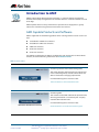
switches, watch the following videos from our YouTube channel.
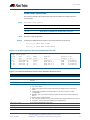
AMF overview videos
Video
Topic
Introducing Software Defined Networking (SDN)
This video describes SDN, its key drivers, where it fits
in the networking world, and what Allied Telesis has
done to meet these emerging requirements.
Click the following link to view the video:
www.alliedtelesis.com/videos/whatissdn
Introducing AMF
This video describes AMF and how this powerful suite
of management tools can automate your everyday
network administration tasks.
Click the following link to view the video:
www.alliedtelesis.com/videos/introducingamf
AMF Software Reference Supplement for Allied Telesis x-Series Switches
C613-50031-01 REV B
AlliedWare PlusTM Operating System - Software Version 5.4.3-1.4 and later
5
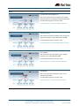
Video
Topic
Centralized Network Management
This video shows how the management of modern
complex networks can be greatly simplified with AMF.
Click the following link to view the video:
www.alliedtelesis.com/videos/AMFmanagement
Auto-provisioning
This video shows how the addition of new switches to
expand the network can be automated with AMF.
Click the following link to view the video:
www.alliedtelesis.com/videos/AMFautoprovisioning
Auto-Upgrade
This video shows how upgrading a large complex
network can be automated with AMF.
Click the following link to view the video:
www.alliedtelesis.com/videos/AMFautoupgrade
Auto-Backup
This video shows how network back-ups can be
automated with AMF.
Click the following link to view the video:
www.alliedtelesis.com/videos/AMFautobackup
AMF Software Reference Supplement for Allied Telesis x-Series Switches
6
AlliedWare PlusTM Operating System - Software Version 5.4.3-1.4 and later
C613-50031-01 REV B
Video
Topic
AMF Live Demo: Zero-Touch Auto Recovery
This video shows a live demonstration of the autorecovery feature of AMF. A network device is powered
off to simulate a failure and the replacement is
automatically re-configured by AMF without any user
intervention.
Click the following link to view the video:
www.alliedtelesis.com/videos/AMFautorecovery
AMF Software Reference Supplement for Allied Telesis x-Series Switches
C613-50031-01 REV B
AlliedWare PlusTM Operating System - Software Version 5.4.3-1.4 and later
7
AMF Software Reference Supplement for Allied Telesis x-Series Switches
8
AlliedWare PlusTM Operating System - Software Version 5.4.3-1.4 and later
C613-50031-01 REV B
Technical Guide
How To | Configure and Use AMF on Allied Telesis Switches
Introduction
The Allied Telesis Management Framework (AMF) is a suite of features that combine to
simplify network management across all supported network devices from the core to the
edge.
AMF also provides simplified unit recovery and firmware upgrade management. The primary
function of AMF is to reduce the management and maintenance overhead on a network,
while improving on responsiveness and handling of device failures within the network.
What information will you find in this document?
This How To Note describes AMF along with its benefits, concepts, and configuration
guidelines. For more information on the commands used in this How To note, see the AMF
Commands chapter later included within this document. Also for those who would like to
know more about AMF, see the Introduction to AMF.
Which products and software version does it apply to?
This How To Note applies to the following Allied Telesis switches running AlliedWare Plus
OS software version 5.4.3 or later:
C613-16174-00 REV D
SwitchBlade™ x8100 family
SwitchBlade™ x908 series switches
x900 series switches
x610 series switches
x510 series switches
alliedtelesis.com x
Introduction
Contents
Introduction............................................................................................................................................................................. 9
What information will you find in this document?................................................................................... 9
Which products and software version does it apply to? ..................................................................... 9
Software feature licensing ................................................................................................................................... 11
The key benefits of AMF .............................................................................................................................................. 12
Unified command-line ......................................................................................................................................... 12
Configuration backup and recovery ............................................................................................................ 12
Rolling firmware upgrade .................................................................................................................................... 12
AMF concepts..................................................................................................................................................................... 13
Network name.......................................................................................................................................................... 13
Node............................................................................................................................................................................... 13
Master nodes.............................................................................................................................................................. 13
Domains........................................................................................................................................................................ 13
Core distance............................................................................................................................................................. 14
Links................................................................................................................................................................................. 15
Crosslinks...................................................................................................................................................................... 15
Working-sets .............................................................................................................................................................. 16
AMF network guidelines ............................................................................................................................................... 16
Retention and use of the ‘manager’ username....................................................................................... 16
Loop-free data plane ............................................................................................................................................. 17
Aggregators................................................................................................................................................................. 17
VCStacks....................................................................................................................................................................... 17
AMF external removable media...................................................................................................................... 17
AMF interaction with QoS and ACLs.......................................................................................................... 18
NTP and AMF ........................................................................................................................................................... 18
Configuring AMF ............................................................................................................................................................... 19
Simple AMF example with a single master ............................................................................................... 19
Verifying the AMF network................................................................................................................................ 24
Using the AMF network................................................................................................................................................ 25
AMF backups.............................................................................................................................................................. 25
Safe removal of external storage media..................................................................................................... 26
Performing a manual backup ...................................................................................................................................... 27
Backups on VCStacks running as AMF masters .............................................................................................. 28
Node recovery................................................................................................................................................................... 30
Automatic node recovery .................................................................................................................................. 30
A “Clean” node ........................................................................................................................................................ 31
Manual node recovery.......................................................................................................................................... 31
Node recovery on VCStacks............................................................................................................................ 32
AMF safe configuration .................................................................................................................................................. 34
How can I undo a safe configuration?.......................................................................................................... 35
Page 10 | How to Configure and Use AMF on Allied Telesis Switches
Introduction
Adding a preconfigured device to the network ..............................................................................................36
Using the unified CLI with working-sets...............................................................................................................38
The working-set........................................................................................................................................................38
Working-set groups ................................................................................................................................................38
Automatic working-set groups.........................................................................................................................39
User-defined working-set groups....................................................................................................................40
Executing commands on working-sets ........................................................................................................41
Interactive commands ...........................................................................................................................................43
Rolling-reboot firmware upgrade.............................................................................................................................44
Performing a rolling reboot upgrade.............................................................................................................45
Software feature licensing
A feature licence is required for each AMF master node in the AMF network. AMF master
node licences are available for the SBx8100 and SBx908 platforms. A licence is not required
for AMF member nodes.
How to Configure and Use AMF on Allied Telesis Switches | Page 11
The key benefits of AMF
The key benefits of AMF
The key benefits of AMF include its: unified command-line, simple configuration backup and
recovery process, and time-saving rolling firmware upgrade.
Unified command-line
The primary means of configuring and controlling AlliedWare Plus (AW+) units is via a textbased command-line interface. In existing networks, this command-line is available via a serial
console port as well as remote login sessions (e.g. SSH).
Under AMF, this concept is extended to allow control of an entire network of AW+ devices
(or any part thereof) via a single session. It allows a network administrator to nominate all
nodes or a subset of nodes within the AMF network, known as a working-set. Commands can
then execute concurrently across all nodes in the nominated working-set as if it were a single
unit. Any existing configuration or diagnostic actions can thus be applied to multiple devices,
reducing repetitive and error-prone roll-out procedures. In this way, regularities in network
design can be used to reduce maintenance cost and complexity, while still retaining complete
flexibility in network design and control. Currently AMF supports a network of up to 42
nodes, and multiple AMF networks can exist side by side across a single physical network. A
Virtual Chassis Stack (VCStack) is considered to be just one node by AMF.
Configuration backup and recovery
An AMF network has a master node that uses external storage to automatically backup
complete configuration information of all the other nodes, including boot configuration,
firmware, licenses, and user scripts. If a node subsequently fails, the AMF will automatically
recognize and reconfigure an unconfigured replacement unit, completely recreating the
stored state of the failed unit into the replacement unit. This new unit will then reboot and
resume service, without any need for user intervention beyond physical hardware
replacement. In this way AMF provides a complete zero-touch recovery solution.
If preferred (or if automatic recovery fails), the new hardware will be held in a safe nonforwarding state—ready for a network administrator to configure remotely via the AMF
unified command-line.
Rolling firmware upgrade
Firmware upgrades on a production network are typically an infrequent but sensitive and
labour-intensive process. AMF supports automated firmware roll-out to a user-selected
subset of nodes. The user selects a target group of nodes, and the location where the new
firmware is stored, then AMF takes care of the rest. Nodes are upgraded in a serial fashion,
with each node tested before continuing with subsequent nodes.
If an upgrade fails, the upgrade process is automatically terminated and that node is reverted
to the previous firmware version. In this way firmware updates are almost completely handsfree, while providing confidence that a bad update will not result in loss of service.
Page 12 | How to Configure and Use AMF on Allied Telesis Switches
AMF concepts
AMF concepts
Network name
The AMF network name is used to determine the AMF network a node belongs to. All
nodes within an AMF network must be configured with the same AMF name.
Node
AMF members are commonly referred to as nodes. A node can be a single switch, or a
VCStack.
Master nodes
AMF master nodes are user defined and form the core domain of the AMF network. They
are:
responsible for performing file system backups of all nodes in the AMF network.
required before an AMF network can form; at least one must be present.
AMF master nodes are supported on SBx908 and SBx8100 platforms; an AMF licence is
required for each master. Only one AMF master license is required even if two CFCs are
installed. The license is for the chassis, not the CFC.
Notes: A VCStack needs to have consistent licensing on all stack members, so an AMF master
license would be required on both devices in an SBx908 stack.
When more than one AMF master node exists in an AMF network, it is important to
know that these operate completely independently of each other, and there is no
synchronization between AMF master nodes.
For redundancy, you can have multiple master nodes, each acting as a master for the
network. But, there is no synchronization of status or data files between the masters.
The behaviour of a master node is not changed at all by the presence of other master
nodes.
Domains
Every AMF node belongs to an AMF domain, which may be comprised of multiple nodes or
only a single node. AMF master nodes are included in the core domain, and all other
domains are rooted in the core domain. AMF domains are determined by AMF crosslinks,
(see page 15). All nodes connected via AMF crosslinks are part of the same domain, and
How to Configure and Use AMF on Allied Telesis Switches | Page 13
AMF concepts
nodes connected via regular AMF links will be part of a higher or lower domain depending
on whether they are closer to or further away from the core domain. Nodes within a
domain must be connected in either a chain or ring topology.
This means that a maximum of two crosslinks should be configured on any single node. The
advantage of an AMF domain is that two links from a domain to a single higher level domain
(closer to the core) will provide redundant AMF links. It is recommended that an AMF
domain should only be connected to a single higher level domain, though it may be
connected to multiple lower level domains.
It is recommended that:
The maximum number of nodes per domain is 12 for SBx8100, x908, x900, x610, and
x510.
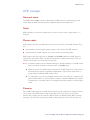
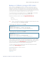
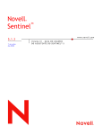
Core distance
This is the distance (hop count) between a domain and the Core domain. The Core domain
has a Core distance of 0, and the maximum recommended Core distance in an AMF
network is 8.
F e
AM r nod
ste
Ma
Node ID1
F e
AM er nod
st
Ma
mb
F de
AM er no
Me
Node ID3
Node ID2
mb
F de
AM er no
Me
Node ID5
RE
mb
mb
Node ID6
CO
F de
AM er no
Me
F de
AM er no
Me
Node ID4
TAN
CE
F de
AM er no
mb
Me
Node ID7
CO
RE
CE
mb
Node ID8
CO
RE
DIS
TAN
CE
Figure 1: AMF domains and Core distance
Page 14 | How to Configure and Use AMF on Allied Telesis Switches
DIS
TAN
F de
AM er no
Me
amf-crosslink
amf-link
Domain Controller
Backup Domain Controller
DIS
2
1
0
AMF concepts
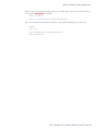
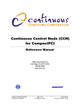
Links
AMF links are used to connect AMF nodes to AMF nodes in other AMF domains, and are
either uplinks or downlinks. Uplinks are used to connect a domain with a higher Core
distance (further from the Core) to a domain with a lower Core distance (closer to the
Core. Downlinks are used to connect a domain with a lower Core distance to a domain with
a higher Core distance.
AMF links are used to pass AMF management traffic between nodes, but can also be used to
carry other network traffic. Configuring an interface as an atmf-link will automatically put
the port into trunk mode. An AMF link must have at least one tagged VLAN, or have a native
VLAN defined. An AMF link can be either a single link or a static aggregator.
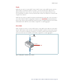
Crosslinks
AMF crosslinks are used to connect AMF nodes to other AMF nodes within the same AMF
domain. AMF master nodes must be connected using AMF crosslinks to ensure they are part
of the core domain. Configuring an interface as an atmf-crosslink will automatically put the
port into trunk mode. A crosslink can be either a single link or a static aggregator.
Core Domain
Uplink
F de
AM er no
mb
Me
Crosslink
Downlink
Figure 2: AMF uplinks, downlinks, and crosslinks
How to Configure and Use AMF on Allied Telesis Switches | Page 15
AMF network guidelines
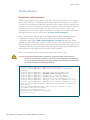
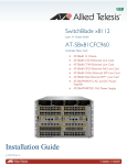
Working-sets
An AMF working-set is a set of nodes, which is either arbitrarily user defined, or one of the
pre-defined working-set groups (see "Working-set groups" on page 38). Specifying or
selecting a working-set allows CLI commands to be executed on all nodes within the
selected working-set with a single command. A working-set can be defined, selected and
configured from any node within an AMF network.
AMF Network
r
ste
Ma
1
r1
e
mb
r
ste
Ma
Me
2
r3
e
mb
Me
r4
r2
e
mb
Me
e
mb
Me
AMF
working-set
er
mb
Me
5
er
mb
Me
6
Figure 3: AMF working-set containing nodes Master1, Member1, Member2, and Member6
AMF network guidelines
Retention and use of the ‘manager’ username
The default username for an Alliedware Plus login is manager, with a documented default
password. Users should change this password on all their nodes to provide login security. In
order to centrally manage nodes undergoing automated node recovery, or to expand the
network by adding a new unconfigured node, it will be necessary to login with the default
manager username.
It is possible to add new usernames and passwords to nodes, but to retain the ability to
centrally manage the network, usernames should be uniformly configured across all AMF
nodes within the AMF network.
Page 16 | How to Configure and Use AMF on Allied Telesis Switches
AMF network guidelines
Loop-free data plane
The current version of AMF does not control the data plane, so it is a requirement that the
network is configured such that the data plane is kept loop free.
Note:
Currently AMF does not support the use of STP on links between AMF nodes. Use
of STP with redundant network links has the potential to block AMF control
connections, and also could lead to periods of traffic leakage during the start of
automatic node recovery. Hence, if there are physical loops in any of the data VLANs
in the network, then EPSR must be used as the protection mechanism for those loops.
Aggregators
Dynamic Aggregators (LACP) cannot be used on ports configured as AMF links or crosslinks. Therefore any aggregated links in an AMF network need to be configured as static
aggregators.
VCStacks
If any VCStacks are included as AMF nodes it is a requirement that the VCS virtual MAC
feature is enabled to ensure correct operation of the AMF network. If the VCStack is running
as an AMF master node it is also a requirement that removable external storage media is
installed in both stack members.
AMF external removable media
All AMF master nodes require external storage media (e.g. USB memory stick, SD card) to
be installed. This external storage is used to hold a backup of all relevant files from all nodes
within the AMF network, including other master nodes, so it must be large enough to be able
to accommodate all of the backed up files. Files that are backed up include all configuration
files, release files, and scripts, but not core dumps, exception logs, or technical support files.
Typically a 4GB capacity external media device would be of sufficient size to hold backups for
a 40 node AMF network.
When using Dual CFCs in a SBx8100, a memory stick is required in both CFCs.
How to Configure and Use AMF on Allied Telesis Switches | Page 17
AMF network guidelines
AMF interaction with QoS and ACLs
It's important that ACL and QoS rules do not block any traffic on VLAN 4091 and 4092 as
they are the default AMF control VLANs. Likewise ACL and QoS rules should not block any
Layer 3 traffic on 172.31.0.* or 172.31.128.* as these are the default AMF management traffic
subnets. Packets with protocol type 0xfbae and BPDU packets that use the MAC address:
0180.c200.002e should also not be blocked.
Note:
The AMF control VLANs and AMF management subnets can be manually changed.
With AMF enabled, the number of ACLs on the x510 switch decreases from 249 to 248. If
this is an issue, then you can disable AMF, which will allow the previous maximum of 249.
Enabling AMF on the x610 switch provides 2048 ACLs.
NTP and AMF
AMF uses NTP to synchronize the system clocks across nodes within the network. For this to
operate there must either be one or more external NTP servers configured on the network,
or one single AMF node must be configured as the NTP 'master' using the command ntp
master 11.
Note:
It is not valid to have an NTP master configured on an AMF node anywhere in the
network if any external NTP servers exist, as this will prevent clock synchronization.
If there is no external server, and instead the network has a node configured with the
command: ntp master 11, the following commands will work as expected:
awplus (config)#atmf working set group all
awplus (config)#clock set 16:51:00 24 Aug 2012
The clock set command may also be used prior to configuring an external NTP server to
get the network roughly up to the correct time, so that NTP will synchronize faster.
The primary function of NTP within an AMF network is to ensure that time and date stamps
on backups are consistent across member nodes within the backup. This is particularly
important in an AMF network that has multiple AMF master nodes, to ensure that node
recovery is performed with the most up to date backup.
Page 18 | How to Configure and Use AMF on Allied Telesis Switches
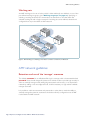
Configuring AMF
Configuring AMF
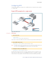
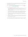
The following configuration example uses a simplified network to explain the steps required
to configure AMF.
Simple AMF example with a single master
F
AM ter 1
s
Ma
por
m
Me
t1.1
.1
r1
por
.1
be
por
por
t1.1
t1.1
por
.3
t1.0
.1
por
por
m
Me
t1.1
.2
r3
t1.1
r2
por
.2
.1
be
.2
por
t1.1
m
Me
be
por
t1.1
t1.1
.3
t1.0
.1
er
mb
Me
4
Crosslink
Link
Figure 4: Simple AMF network
Configuration
AMF Master
1. Set the host name.
awplus#conf t
awplus(config)#hostname AMF_Master
Host names are used as the AMF node name and must be unique within the AMF network.
2. Set the AMF network name.
AMF_Master (config)#atmf network-name atmf1
Note:
The AMF network name must be the same on all nodes within the AMF network, and
the device must be rebooted before the AMF network name takes effect.
3. Configure the device as the AMF master.
AMF_Master (config)#atmf master
An AMF network must have at least one master configured. A licence is required for each
AMF master in the AMF network. If an AT-x8100 with dual CFCs is configured as an AMF
master a licence is only required on the CFC master, as the licence with be synchronized
How to Configure and Use AMF on Allied Telesis Switches | Page 19
Configuring AMF
across CFCs. If an AT-x908 VCStack is configured as an AMF master, a licence is required to
be installed on both stack members.
4. Configure the data VLANs.
AMF_Master(config)#vlan database
AMF_Master(config-vlan)#vlan 2-3
5. Disable RSTP globally (this is enabled by default).
AMF_Master (config)#no spanning-tree rstp enable
6. Configure ports as AMF-links.
AMF_Master(config)#int port1.1.1-1.1.2
AMF_Master(config-if)#switchport atmf-link
7. Configure data VLANs on AMF-links as required.
AMF_Master (config-if)#switchport trunk allowed vlan add 2-3
8. Save the configuration and reboot the switch.
AMF_Master #copy running-config startup-config
Building configuration...[OK]
AMF_Master#reload
Are you sure you want to reboot the whole chassis? (y/n): y
Configuration
Member 1
1. Set the host name.
awplus#conf t
awplus(config)#hostname Member1
Host names must be unique within the AMF network.
2. Set the AMF network name.
Member1(config)#atmf network-name atmf1
Note:
The AMF network name must be the same on all nodes within the AMF network, and
the device must be rebooted before the AMF network name takes effect.
3. Configure data VLANs.
Member1(config)#vlan database
Member1(config-vlan)#vlan 2-3
4. Disable RSTP globally (this is enabled by default).
Member1(config)#no spanning-tree rstp enable
Page 20 | How to Configure and Use AMF on Allied Telesis Switches
Configuring AMF
5. Configure ports as AMF-links.
Member1(config)#int port1.1.1,port1.1.3
Member1(config-if)#switchport atmf-link
6. Configure data VLANs on the AMF links as required.
Member1(config-if)#switchport trunk allowed vlan add 2-3
7. Configure AMF-crosslink.
Member1(config)#int port1.1.2
Member1(config-if)#switchport atmf-crosslink
Member1(config-if)#switchport trunk native vlan none
Note:
AMF links and crosslinks are not required to be configured with data VLANs and can
be used solely to provide AMF management VLAN redundancy.
8. Save the configuration and reboot the switch.
Member1#copy running-config startup-config
Building configuration...
[OK]
Member1#reload
reboot system? (y/n): y
Configuration
Member 2
1. Set the host name.
awplus#conf t
awplus(config)#hostname Member2
Note:
Hostnames are used as the AMF node name and must be unique within the AMF
network..
2. Set the AMF network name.
Member2(config)#atmf network-name atmf1
Note:
The AMF network name must be the same on all nodes within the AMF network, and
the device must be rebooted before the AMF network name takes effect.
3. Configure a data VLAN.
Member2(config)#vlan database
Member2(config-vlan)#vlan 2-3
4. Disable RSTP globally (this is enabled by default).
Member2(config)# no spanning-tree rstp enable
How to Configure and Use AMF on Allied Telesis Switches | Page 21
Configuring AMF
5. Configure ports as AMF-links.
Member2(config)#int port1.1.1,port1.1.3
Member2(config-if)#switchport atmf-link
6. Configure data VLANs on the AMF-links as required.
Member2(config-if)#switchport trunk allowed vlan add 2-3
7. Configure AMF-crosslink.
Member2(config)#int port1.1.2
Member2(config-if)#switchport atmf-crosslink
Member2(config-if)#switchport trunk native vlan none
Note:
AMF links and crosslinks are not required to be configured with data VLANs and can
be used solely to provide AMF management VLAN redundancy.
8. Save the configuration and reboot the switch.
Member2#copy running-config startup-config
Building configuration...
[OK]
Member2#reload
reboot system? (y/n): y
Configuration
Member 3
1. Set the host name.
awplus#conf t
awplus(config)#hostname Member3
Host names must be unique within the AMF network.
2. Set the AMF network name.
Member3(config)#atmf network-name atmf1
Note:
The AMF network name must be the same on all nodes within the AMF network, and
the device must be rebooted before the AMF network name takes effect.
3. Configure data VLANs on the AMF-link.
Member3(config)#vlan database
Member3(config-vlan)#vlan add 2-3
4. Disable RSTP globally (this is enabled by default).
Member3(config)#no spanning-tree rstp enable
Page 22 | How to Configure and Use AMF on Allied Telesis Switches
Configuring AMF
5. Configure ports as AMF-links.
Member3(config)#int port1.0.1
Member3(config-if)#switchport atmf-link
6. Configure data VLANs on the AMF links as required.
Member3(config-if)#switchport trunk allowed vlan add 2-3
7. Save the configuration and reboot the switch.
Member3#copy running-config startup-config
Building configuration...
[OK]
Member3#reload
reboot system? (y/n): y
Configuration
Member 4
1. Set the host name.
awplus#conf t
awplus(config)#hostname Member4
Host names must be unique within the AMF network.
2. Set the AMF network name.
Member4(config)#atmf network-name atmf1
Note:
The AMF network name must be the same on all nodes within the AMF network, and
the device must be rebooted before the AMF network name takes effect.
3. Configure data VLANs
Member4(config)#vlan database
Member4(config-vlan)#vlan 2-3
4. Disable RSTP globally (this is enabled by default).
Member4(config)#no spanning-tree rstp enable
5. Configure ports as AMF-links.
Member4(config)#int port1.0.1
Member4(config-if)#switchport atmf-link
6. Configure data VLANs on the AMF links as required.
Member4(config-if)#switchport trunk allowed vlan add 2-3
How to Configure and Use AMF on Allied Telesis Switches | Page 23
Configuring AMF
7. Save the configuration and reboot the switch.
Member4#copy running-config startup-config
Building configuration...
[OK]
Member4#reload
reboot system? (y/n): y
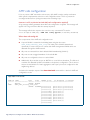
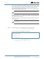
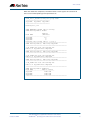
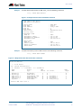
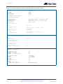
Verifying the AMF network
To check that all nodes have joined the AMF network use the show atmf summary
command, which can be executed from any node in the AMF network:
AMF_Master#show atmf summary
ATMF Summary Information:
ATMF Status
: Enabled
Network Name
: atmf1
Node Name
: AMF_Master
Role
: Master
Current ATMF Nodes
: 5
AMF_Master#
The Current ATMF Nodes field in the output above shows that all 5 nodes have joined the
AMF network.
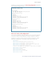
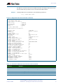
Use the show atmf nodes command to check information on individual nodes:
AMF_Master#show atmf nodes
Node Information:
* = Local device
SC = Switch Configuration:
C = Chassis
S = Stackable
N = Standalone
Node
Device
ATMF
Node
Name
Type
Master
SC Parent
Depth
--------------------------------------------------------------------* AMF_Master
AT-SBx81CFC400
Y
C
none
0
Member1
SwitchBlade x908
N
S
AMF_Master
1
Member2
SwitchBlade x908
N
S
AMF_Master
1
Member4
x510-52GTX
N
S
Member2
2
Member3
x510-52GTX
N
S
Member2
2
Current ATMF node count 5
Note:
The Parent field refers to the parent domain and not the upstream device. In the
example output above, Member2 is the domain controller for the parent domain for
Member3 and Member4.
Page 24 | How to Configure and Use AMF on Allied Telesis Switches
Using the AMF network
Using the AMF network
AMF backups
AMF backups are an essential part of AMF network operation, as they are the mechanism by
which AMF master nodes update their records of the AMF network. By default, AMF master
nodes are configured to perform automatic scheduled backups of the entire AMF network
once per day at 3.00am. AMF backups are stored on external removable media (e.g. USB
Flash stick, SD card), thus it is a requirement that all AMF masters have external removable
media installed that is of sufficient capacity to hold all of the relevant files stored in the Flash
by every node in the AMF network.
Typically a 4GB capacity external media device would be of sufficient size to hold backups for
a 40 node AMF network.
The AMF node backup system has been designed such that the external media used to store
the backup data can still be used to store other data, however care needs to be taken to
ensure that enough space is reserved for future AMF backups.
AMF requires up to 128MB backup space for SBx8100 nodes and up to 64MB backup
space for other nodes. The show atmf backup command output will provide warnings
if capacity on the backup media falls below a safe level.
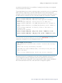
Here is some example output of the show atmf backup command showing a backup
media space warning:
master1#show atmf backup
Scheduled Backup ......
Schedule ............
Next Backup Time ....
Backup Media ..........
Disabled
1 per day starting at 12:45
25 May 2012 12:45
SD (Total 3827.0MB, Free 7.1MB)
WARNING: Space on backup media is below 64MB
Current Action ........ Idle
Started ............. Current Node ........ -
How to Configure and Use AMF on Allied Telesis Switches | Page 25
Using the AMF network
Safe removal of external storage media
Removing external storage media, or rebooting the master node, while an AMF backup is
underway could potentially cause corruption to files in the backup. Although files damaged as
a result of mishandling backup media will be replaced during the next backup cycle, if the file
system on the media becomes damaged it may require reformatting before being inserted
into the AMF master. To avoid any damage to the AMF backup files or file system it is
recommended that the following procedure is followed before rebooting or removing any
external storage media from an AMF master.
1. Disable backups to prevent a scheduled backup from occurring while the card is being
removed.
2. Terminate any backup already in process.
3. Verify that it is safe to remove the media by checking for a Disabled scheduler and Idle
backup.
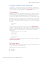
Here is an example output showing the safe external storage media removal procedure:
master1#conf t
master1(config)#no atmf backup enable
master1(config)#exit
master1#atmf backup stop
master1#show atmf backup
Scheduled Backup ......
Schedule ............
Next Backup Time ....
Backup Media ..........
Current Action ........
Started .............
Current Node ........
...
Disabled
1 per day starting at 12:45
25 May 2012 12:45
SD (Total 3827.0MB, Free 3257.1MB)
Idle
-
Once the media has been reinstalled, ensure that the backup scheduler is re-enabled:
master1#conf t
master1(config)#atmf backup enable
master1(config)#exit
Page 26 | How to Configure and Use AMF on Allied Telesis Switches
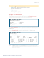
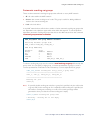
Performing a manual backup
Performing a manual backup
Whenever a new device is added to the AMF network or when the configuration has
changed on a member node, it is always advisable to perform a manual backup from the
AMF master in order to ensure the removable media installed on the master node has an up
to date backup of all nodes within the AMF.
To perform a manual backup of the entire AMF network, on the AMF master enter the
command atmf backup now:
AMF_Master#atmf backup now
Backup successfully initiated
AMF_Master#
To check the status of the AMF backup use the command show atmf backup.
Example output of the show atmf backup command during backup:
AMF_Master#show atmf backup
Scheduled Backup ...... Enabled
Schedule ............ 1 per day starting at 03:00
Next Backup Time .... 14 Dec 2012 03:00
Backup Media .......... USB (Total 3692.6MB, Free 1782.7MB)
Current Action ........ Doing manual backup
Started ............. 13 Dec 2012 05:20
Current Node ........ Member1
Node Name
Date
Time
In ATMF On Media Status
-----------------------------------------------------------------------------AMF_Master
13 Dec 2012 05:20:16
Yes
Yes
Good
Member1
Yes
Yes
Member2
Yes
No
Member3
Yes
No
Member4
Yes
No
-
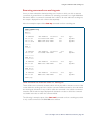
Example output of the show atmf backup command after backup has completed:
AMF_Master#show atmf backup
Scheduled Backup ...... Enabled
Schedule ............ 1 per day starting at 03:00
Next Backup Time .... 13 Dec 2012 03:00
Backup Media .......... USB (Total 3692.6MB, Free 1651.1MB)
Current Action ........ Idle
Started ............. Current Node ........ Node Name
Date
Time
In ATMF On Media Status
-----------------------------------------------------------------------------ATMF_Master
13 Dec 2012 05:20:16 Yes
Yes
Good
Member1
13 Dec 2012 05:20:27 Yes
Yes
Good
Member2
13 Dec 2012 05:20:40 Yes
Yes
Good
Member3
13 Dec 2012 05:20:52 Yes
Yes
Good
Member4
13 Dec 2012 05:21:08 Yes
Yes
Good
Note:
The file system used by the AMF backup does not support the backing up of files that
have the same name but have different case (e.g. “test.txt” and “TEST.txt”), and only
one of these files will be stored in the backup. For this reason it is recommended that
all files on a node have unique file names.
How to Configure and Use AMF on Allied Telesis Switches | Page 27
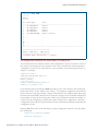
Backups on VCStacks running as AMF masters
Backups on VCStacks running as AMF masters
When a VCStack or SBx8100 with dual CFCs is running as an AMF master node, it is
important to note that an AMF backup will only occur on the external removable media
installed in the VCS master (or Active CFC). This means that following a failover event, the
new VCS master will not have an AMF backup stored on its external storage media, and will
not be able to provide configuration backup and recovery when required.
To avoid this situation, the recommended solution is to use trigger scripts to automatically
perform a manual backup of the AMF network following a failover event.
Example manual backup activation script called triggered-atmfbackup.scp:
enable
wait 180
atmf backup now
Note:
There is a syntax difference between the configuration commands required to create
the necessary trigger on the SBx8100 and SBx908.
Example trigger script configuration for the SBx8100:
awplus#conf t
awplus(config)#trigger 1
awplus(config-trigger)#type chassis active-CFC-fail
awplus(config-trigger)#script 1 triggered-atmfbackup.scp
Example trigger script configuration for the SBx908:
awplus#conf t
awplus(config)#trigger 1
awplus(config-trigger)#type stack master-fail
awplus(config-trigger)#script 1 triggered-atmfbackup.scp
If there are multiple AMF master nodes in the network, you may also want to use a trigger
script or perform a manual backup of all master nodes whenever there is a failover event to
ensure that all backups are up to date. Create an atmf working-set group which contains all
master nodes, and then use the atmf working-set command in the trigger script to
execute the manual backup on all nodes within the working set group.
To create a working-set containing all AMF master nodes, first manually select all AMF
masters using the atmf working-set command:
Master#atmf working-set Master1,Master2
===================
Master1, Master2:
===================
Working set join
atmf1[2]#
Page 28 | How to Configure and Use AMF on Allied Telesis Switches
Backups on VCStacks running as AMF masters
Next, create a user defined working-set group containing the nodes in the current workingset using the atmf group command:
atmf1[2]#conf t
atmf1[2](config)#atmf group AMF_masters
Here is an example manual backup activation script called atmfbackup_all_masters.scp:
enable
wait 180
atmf working-set group AMF_masters
atmf backup now
How to Configure and Use AMF on Allied Telesis Switches | Page 29
Node recovery
Node recovery
Automatic node recovery
AMF has been designed so that when a node fails it can be replaced with an unconfigured
device of the same type, and AMF will automatically upgrade and configure the new device
from the most recent backup. Often the replacement device will be a factory default, brand
new “out of the box” device, but it may be that you want to replace the failed unit with one
that has been previously used elsewhere. In this instance it is necessary to return the
replacement device to a “clean” state so that AMF can recognize it as a suitable replacement,
and begin automatic recovery. (See section "A “Clean” node" on page 31)
When a failed node is replaced with an unconfigured device, AMF immediately disables
forwarding on the device, shuts down all non-AMF ports, and applies the AMF safe
configuration. (See section "AMF safe configuration" on page 34.) AMF then checks
whether any of the AMF master nodes has a valid backup for the replacement node, and if it
finds one it begins to attempt automatic node recovery. Once automatic node recovery has
completed, it will then reboot the replacement node which will then rejoin the AMF network
with identical files and configuration, to the failed node it replaced.
Here is some example console output showing automatic node recovery:
Warning: No changes should be made to the device's configuration while a node recovery is underway. A log message will appear on the console or other logged in session indicating
when recovery has finished (whether successfully or with errors). This message can also be found by viewing the log with the show log command. 23:03:15 awplus ATMF[863]: ATMF network detected
23:03:15 awplus ATMF[863]: ATMF safe config applied (forwarding
disabled)
23:03:25 awplus ATMF[863]: Shutting down all non ATMF ports
23:03:26 x510_1 ATMF[863]: Automatic node recovery started
23:03:26 x510_1 ATMF[863]: Attempting to recover as x510_1
23:03:26 x510_1 ATMF[863]: Checking master node availability
23:03:32 x510_1 ATMF[863]: Master has joined. 2 members in total.
23:03:32 x510_1 ATMF[863]: x908_VCS_2 has joined. 3 members in total.
23:03:32 x510_1 ATMF[863]: x908_VCS_1 has joined. 4 members in total.
23:03:37 x510_1 ATMFFSR[2950]: Retrieving recovery data from master
node Master
23:05:18 x510_1 ATMFFSR[2950]: File recovery from master node
succeeded. Node will now reboot
Flushing file system buffers...
Unmounting any remaining filesystems...
Restarting system.
Page 30 | How to Configure and Use AMF on Allied Telesis Switches
Node recovery
A “Clean” node
The recommended procedure for returning a device to a “clean” state is to remove any preexisting boot configuration, including any backup boot configuration, and delete all
configuration files from Flash. If the device you are cleaning has previously had VCStack
enabled, it is also necessary to delete the stacking configuration file.
For example:
configure terminal
no boot config-file
no boot config-file backup
exit
delete force *.cfg
delete force .configs/stk.conf
Any user created folders in Flash will have to be removed. Firstly, identify if any user created
folders exist.
cd flash:
dir
...
0 drwx Aug 20 2012 15:01:44
...
example_dir/
A folder is identified as having permissions drwx. Once you have identified them, any user
created folder and its contents should be removed.
rmdir force example_dir
In addition, any external media installed in the device should be physically removed. If you are
unable to remove the external media from the device then make sure any autoboot.txt files
are removed from the external media. This may be achieved with one of the following
commands:
delete force card:autoboot.txt
delete force usb:autoboot.txt
Note:
The procedure above contains the minimum requirements to return a device to a
clean state in order for AMF automatic node recovery to work. However, it should be
noted that any other user files that remain in Flash will be overwritten during the
automatic recovery process. If there are any files stored in the Flash of the
replacement device that need to be retained, these files should be backed up prior to
installing the device into the AMF network.
Manual node recovery
There are certain situations where, for a number of different reasons, automatic recovery
may fail. Automatic recovery has been deliberately designed to be cautious in its approach to
recovering a node and for reasons such as:
The backup stored on the AMF masters not having a “Good” status
The replacement device is of a different type to the node being replaced
How to Configure and Use AMF on Allied Telesis Switches | Page 31
Node recovery
When these situations occur, automatic node recovery may fail.
If automatic node recovery fails, the replacement device will have AMF safe configuration
mode applied, (see section "AMF safe configuration" on page 34). If automatic node
recovery fails, you may wish to proceed with manual node recovery, which can be initiated by
entering the command:
atmf recover {<node_name>} {<master_node_name>}
Where:
node_name is the host name of the device you wish to recover.
master_node_name is the host name of the AMF master that contains the backup you
want to use for the recovery.
Here is an example showing manual recovery:
awplus#atmf recover x510_1 Master
This command will erase ALL flash contents. Continue node recovery?
(y/n)y
Manual node recovery successfully initiated
x510_1#23:15:32 x510_1 ATMFFSR[8477]: Retrieving recovery data from
master node Master
23:17:17 x510_1 ATMFFSR[8477]: Manual node recovery completed
x510_1#
Note:
The manual recovery command will bypass the usual checks performed by automatic
node recovery, it is important to be confident that the backup configuration stored on
the specified AMF master is correct prior to executing the command.
If the replacement device is of a different type to the one stored in the backup on the
specified AMF master node, the incompatible release file from the backup will not be copied
to the replacement device. Instead, the existing release on the replacement device will be
used, in order to ensure the device is able to join the AMF network and function correctly.
Node recovery on VCStacks
Node recovery on VCStacks that are part of an AMF network is somewhat different to node
recovery of standalone devices. This is because VCStack has its own node recovery
mechanism which has different requirements to AMF.
Typically a failure on a VCStack will only affect one stack member.
In this instance, so long as:
The replacement device is running a compatible firmware version
The Stack ID on the replacement device is set to the same ID as the device being replaced
The replacement device is installed with the same licences as other stack members
Then, VCStack will synchronize the configuration and firmware.
Page 32 | How to Configure and Use AMF on Allied Telesis Switches
Node recovery
In the extremely unlikely situation of needing to replace an entire VCStack that is a member
of an AMF network, you can use AMF automatic node recovery to first recover stack ID 1,
which will become the VCstack master.
Note:
The replacement device which will become the VCStack master must be a clean unit,
(see the section "A “Clean” node" on page 31).
The procedure for recovering an entire stack is as follows:
1. Connect a clean device to the AMF network, and power it on. The connections into the
AMF network should be between the appropriately configured AMF links on the
neighboring node, and the ports previously configured as AMF links in the backup for the
failed node configuration.
2. The AMF network should detect the replacement device and begin automatic node
recovery. Wait until automatic node recovery completes and check that the replacement
device has come up correctly as VCStack ID 1, and that the configuration is correct.
3. Configure the next replacement device as VCStack ID 2. Ensure it is installed with a
compatible release and the same set of licences that exist on ID 1. Connect the VCStack
cables and power it on.
4. VCStack ID 1 should detect ID 2 and synchronize the configuration and firmware release.
Once this has completed, check that the VCStack has formed correctly, and then connect
the remaining network connections.
For any additional VCStack members, repeat the last two steps, ensuring that the VCStack ID
is set to the next sequential value for each additional device that is added to the VCStack.
How to Configure and Use AMF on Allied Telesis Switches | Page 33
AMF safe configuration
AMF safe configuration
If, for any reason, AMF automatic node recovery fails, AMF contains a safety net feature
which puts the replacement node into a safe configuration state. This is to prevent an
unconfigured device from joining the network and creating loops.
How can I tell if my device has had AMF safe configuration applied?
A log message will be generated when AMF safe configuration is applied. This message will
appear in the log some time after the startup sequence.
The message will also be output to the console or any connected VTY session.
22:39:30 awplus ATMF[638]: ATMF safe config applied (forwarding disabled)
What does safe config do?
The components of the AMF safe configuration are:
A special VLAN is created in the disabled state and given the name
atmf_node_recovery_safe_vlan. The index of this VLAN is determined
dynamically to ensure it does not conflict with AMF management VLANs which are
detected through the AMF network.
All ports are removed from their default VLAN membership (VLAN 1).
All ports are set as tagged members of the safe VLAN.
All ports are configured to have no native VLAN.
Additionally, all ports that are not an AMF link or cross-link are shutdown. The links and
crosslinks are detected by AMF and added to the dynamic configuration. This is done to
ensure correct behaviour of static aggregators and Layer 3 protocols configured on the
neighboring devices.
See below for example output of the show vlan brief command for a device in AMF safe
configuration mode:
awplus#sh vlan brief
VLAN ID Name
Type
State
Member ports
(u)-Untagged, (t)-Tagged
======= ================ ======= ======= =======================================
1
default
STATIC ACTIVE
4090
atmf_node_recovery_safe_vlan
STATIC SUSPEND port1.0.1(t) port1.0.2(t) port1.0.3(t)
port1.0.4(t) port1.0.5(t) port1.0.6(t)
port1.0.7(t) port1.0.8(t) port1.0.9(t)
port1.0.10(t) port1.0.11(t)
port1.0.12(t) port1.0.13(t)
port1.0.14(t) port1.0.15(t)
port1.0.16(t) port1.0.17(t)
port1.0.18(t) port1.0.19(t)
port1.0.20(t) port1.0.21(t)
port1.0.22(t) port1.0.23(t)
port1.0.24(t)
Page 34 | How to Configure and Use AMF on Allied Telesis Switches
AMF safe configuration
See below for an example excerpt from the show running-configuration command for a
device in AMF safe configuration mode:
awplus#show running-config
...
!
vlan database
vlan 4090 name atmf_node_recovery_safe_vlan
vlan 4090 state disable
!
interface port1.0.1-1.0.4
shutdown
switchport
switchport mode trunk
switchport trunk allowed vlan add 4090
switchport trunk native vlan none
!
interface port1.0.5
switchport
switchport atmf-link
switchport mode trunk
switchport trunk allowed vlan add 4090
switchport trunk native vlan none
!
interface port1.0.6-1.0.24
shutdown
switchport
switchport mode trunk
switchport trunk allowed vlan add 4090
switchport trunk native vlan none
!
...
How can I undo a safe configuration?
If your node has had AMF safe configuration applied, you can use normal CLI configuration
commands to modify the running-configuration to whatever configuration is required.
See below for an example of returning a device from AMF safe configuration to default
VLAN and port settings. Note - In this example a 24-port device has been used.
awplus#conf t
awplus(config)#interface port1.0.1-port1.0.24
awplus(config-if)#switchport trunk native vlan 1
awplus(config-if)#switchport trunk allowed vlan remove 4090
awplus(config-if)#switchport mode access
% port1.0.5 has ATMF link configured so mode cannot be changed
awplus(config-if)#no shutdown
awplus(config-if)#exit
awplus(config)#vlan database
awplus(config-vlan)#no vlan 4090
awplus(config-if)#end
How to Configure and Use AMF on Allied Telesis Switches | Page 35
Adding a preconfigured device to the network
In order to retain connectivity to the AMF network, AMF link and crosslink settings should
not be changed. In the example above you can see that port1.0.5 is an automatically
configured ATMF link. You can see the error message indicating it was skipped by the
switchport mode access command, as AMF links must be in trunk mode.
Warning: No changes should be made to the device's configuration while a node recovery is
underway. A log message will appear on the console or other logged in session indicating
when recovery has finished (whether successfully or with errors). This message can also
be found by viewing the log with the show log command.
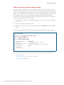
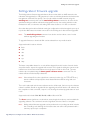
Adding a preconfigured device to the network
In many cases when a new device is to be added to the network, a user will want to fully preconfigure it before connecting it to the network. This is for the obvious reason that it is
generally not a good idea to have an unconfigured device connected to the network.
With AMF it is possible to perform this pre-configuration by cloning the configuration from
the backup of an existing AMF node. The cloned configuration will be applied in a safe way to
the similar node that you wish to join the AMF network. In this way a node can be added to
the network without the need to construct the configuration elements that are common to
another node.
There are two methods that can be used to achieve this:
1. By connecting an unconfigured clean node (see section "A “Clean” node" on page 31),
to the AMF network. Wait for automatic node recovery to fail and the AMF safe
configuration to be applied. Then use the atmf recover command, followed by the node
name of a similar node, to replicate the desired configuration to the new unit.
2. By preconfiguring the new device with the AMF network name, a node name, and an AMF
link prior to connecting it to the AMF network. Then use the atmf recover command
followed by the node name of a similar node, to replicate the desired configuration to the
new unit.
In both methods it is necessary to configure an AMF link on the neighboring node that is to
be connected to the new node, so the new node will be able to join the AMF network.
Note:
It is recommended that the donor node selected is as close as possible to the new
node, and contains the same number of ports or if applicable, has the same XEMs
installed in the same bays. This will limit the number of manual changes that will be
required to the replicated configuration of the new node.
If using the first method described above, it is safe to connect ports other than the AMF link.
This is because forwarding will be disabled and all ports administratively shutdown when the
AMF safe configuration is applied.
If using the second method described above, it is important to only connect the atmf-link
until the configuration can be appropriately edited and the node rebooted. Following this
Page 36 | How to Configure and Use AMF on Allied Telesis Switches
Adding a preconfigured device to the network
procedure ensures that there is no possibility of creating loops by having an unconfigured
node connected to the network.
The example below shows a clean node that has been connected to a port on a neighboring
AMF node that configured as an atmf-link. AMF detects the new node and attempts
automatic node recovery, but because the new node is not present in the backup stored on
the AMF master, the automatic recovery fails and the AMF safe configuration is applied:
04:26:36 awplus ATMF[846]: ATMF network detected
04:26:36 awplus ATMF[846]: ATMF safe config applied (forwarding
disabled)
04:26:46 awplus ATMF[846]: Shutting down all non ATMF ports
04:26:46 awplus ATMF[846]: host_0000_cd28_08cd has left. 0 member in
total.
04:26:46 awplus ATMF[846]: host_0000_cd28_08cd has joined. 1 member in
total.
04:26:46 awplus ATMF[846]: No identity found for this device so
automatic node
recovery is not possible
04:26:53 awplus ATMF[846]: x510_1 has joined. 2 members in total.
04:26:53 awplus ATMF[846]: Master has joined. 3 members in total.
04:26:53 awplus ATMF[846]: x908_VCS_2 has joined. 4 members in total.
04:26:53 awplus ATMF[846]: x908_VCS_1 has joined. 5 members in total.
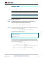
Once automatic recovery has failed you can now use the atmf recover command to
replicate the configuration from the designated similar node:
awplus#atmf recover x510_2
This command will erase ALL flash contents.
(y/n)y
Continue node recovery?
Manual node recovery successfully initiated
awplus#04:38:24 awplus ATMFFSR[15686]: Retrieving recovery data from
master node Maste
r
04:40:11 awplus ATMFFSR[15686]: Manual node recovery completed When the recovery has completed, the new node will be configured to boot from the
cloned configuration, but the configuration will not be applied to the node until it is
rebooted. This way the configuration can be appropriately modified using the AlliedWare
Plus in built editor before the unit is rebooted and the configuration applied.
How to Configure and Use AMF on Allied Telesis Switches | Page 37
Using the unified CLI with working-sets
Using the unified CLI with working-sets
The unified CLI is a central component of AMF. It provides users with a configuration and
display interface that can control the entire AMF network from a single point. Control of the
nodes within an AMF network is provided through the working-set command.
The working-set
An AMF working-set is a set of nodes, which is either arbitrarily user defined or one of the
pre-defined working-set groups. Specifying or selecting a working-set allows CLI commands
to be executed on all nodes within the selected working-set with a single command. A
working-set can be defined, selected and configured from any node within an AMF network.
By default, when you first log into a node that is part of an AMF network, you are implicitly
placed into the working-set group local, a working-set which only contains the local node. In
this instance the CLI prompt when you log in will look the same as on any other AlliedWare
plus device.
Node1>enable
Node1#
To create a working set containing a set of nodes use the command atmf working-set
followed by a comma separated list of the nodes you wish to control. Whenever you select a
working set containing any nodes other than the local device, the CLI prompt will display the
AMF network name, followed by the number of nodes contained in the working set in
square brackets.
Node1#atmf working-set Node1,Node2
==============
Node1, Node2
==============
Working set join
atmf1[2]#
To return to just controlling the local device from any other working set, use the command
atmf working-set group local.
Working-set groups
AMF contains the ability to have working-set groups, so that it is not always necessary to use
a comma separated list to specify a working-set.
AMF working-set groups can be split into two types:
Automatic
User-defined
Page 38 | How to Configure and Use AMF on Allied Telesis Switches
Using the unified CLI with working-sets
Automatic working-set groups
There are three automatic working-set groups that will exist on every AMF network:
1. All—all nodes within the AMF network.
2. Current—the current working-set of nodes. This group is useful for adding additional
nodes to the current working-set.
3. Local—the local device
In any AMF network there will also be a number of other automatic working-set groups that
are dependent on the platform types which exist within the network. To see the platform
dependent automatic working-set groups that exist on the AMF network use the command
show atmf group members automatic:
x908_VCS_1#show atmf group members automatic
Retrieving Automatic groups from:
x510_1 Master x908_VCS_2 x908_VCS_1
ATMF Group membership
Automatic
Groups
poe
x510
SBx8100
x900
Total
Members
1
1
1
2
Members
Master
x510_1
Master
x908_VCS_2 x908_VCS_1
To select a working-set group use the command atmf working-set group followed by the
group name. You can specify a single group, a comma separated list of groups, or even a
comma separated list of individual nodes, followed by a comma separated list of groups:
x908_VCS_1#atmf working-set x510_1,x510_2 group x900
=======================================
x510_1, x510_2, x908_VCS_1, x908_VCS_2:
=======================================
Working set join
atmf1[4]
Note:
If a partially invalid working-set node list or group list is specified, only the valid nodes
or groups will join the working set. If a completely invalid working-set is specified you
will create a working-set containing no nodes and a warning message will be
generated to alert you that the current working-set is empty:
atmf1[3]#atmf working-set group x511
% Warning – working set is now empty
atmf1[0]#
How to Configure and Use AMF on Allied Telesis Switches | Page 39
Using the unified CLI with working-sets
User-defined working-set groups
In addition to the automatic working-set groups, it is also possible to create user-defined
groups for arbitrary sets of nodes that the user may wish to group together. For example, all
AMF master nodes.
To create and use a user-defined working-set group:
1. Create a working-set containing the desired nodes.
2. In global configuration mode use the command: atmf group <group-name>
Master#atmf working-set Master1,Master2
===================
Master1, Master2:
===================
Working set join
atmf1[2]#conf t
atmf1[2](config)#atmf group Masters
You can see all user-defined working-set groups that exist on the AMF network with the
command show atmf group members user-defined
Master1#show atmf group members user-defined
Retrieving User-defined groups from:
x510_1 Master1, Master2, x908_VCS_2 x908_VCS_1
ATMF Group membership
User-defined
Total
Groups
Members
Members
--------------------------------------------------------------------Masters
2
Master1 Master2
Master#
Page 40 | How to Configure and Use AMF on Allied Telesis Switches
Using the unified CLI with working-sets
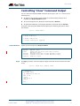
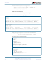
Executing commands on working-sets
Once you have selected the desired working-set of nodes on which you wish to execute
commands, in general there is no difference to executing commands on a single AlliedWare
Plus device. When a command is executed that is valid for all nodes within the working-set,
the output is displayed for each of the nodes separately.
Here is an example output of the show arp command run from a working-set:
atmf1[4]#show arp
=======
Master:
=======
IP Address
172.31.0.1
172.31.0.3
172.31.0.10
MAC Address
eccd.6d7d.a542
0000.cd2b.0329
0000.cd37.0163
Interface
ATMF
ATMF
ATMF
Port
sa1
sa1
sa1
Type
dynamic
dynamic
dynamic
MAC Address
Interface
eccd.6d03.10f9 ATMF
Port
sa4
Type
dynamic
MAC Address
Interface
0000.cd37.1050 ATMF
Port
sa1
Type
dynamic
MAC Address
Interface
0000.cd37.1050 ATMF
Port
sa3
Type
dynamic
=======
x510_1:
=======
IP Address
172.31.0.2
===========
x908_VCS_1:
===========
IP Address
172.31.0.2
===========
x908_VCS_2:
===========
IP Address
172.31.0.2
atmf1[4]#
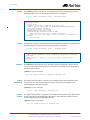
Some commands are invalid for nodes in a working-set
There will be some commands, however, which will only be valid to execute on some of the
nodes within the working-set. In this case the command will be executed on all nodes within
the working-set. However, for any node for which the command is not valid, the command
execution will fail and the output displayed will indicate the nodes on which the command
succeeded and nodes on which the command failed.
The following is example output of the show card command run from a working-set, which
is only a valid command for the SBx8100 series switches:
How to Configure and Use AMF on Allied Telesis Switches | Page 41
Using the unified CLI with working-sets
atmf1[4]# show card
=======
Master:
=======
Slot Card Type
State
-------------------------------------------------------------------1
AT-SBx81GP24
Online
2
AT-SBx81GP24
Online
3
AT-SBx81XZ4
Online
4
AT-SBx81XS6
Online
5
AT-SBx81CFC400
Online (Active)
6
7
8
9
10
11
12
--------------------------------------------------------------------===============================
x510_1, x908_VCS_1, x908_VCS_2:
===============================
% Invalid input detected at '^' marker.
Sub-configuration limitations for some nodes in a working-set
There will also be some instances where a sub-configuration mode is only valid for some of
the nodes in the working-set. One example of this case would be when entering interface
configuration mode for a port that exists on some members of the working-set and not on
others. For example:
atmf1[4]# conf t
atmf1[4](config)#int port2.1.1
===============
Master, x510_1:
===============
% Can't find interface port2.1.1
atmf1[4:2](config-if)#
In the example above the interface port2.1.1 exists on two of the nodes in the working-set,
but doesn’t exist on nodes “Master” and “x510_1”. The interface configuration mode fails for
these nodes and a warning message is output to indicate this. The numbers within the square
brackets next to the AMF network name prompt also change. The first number indicates the
total number of nodes in the working set, and the second number indicates the number of
nodes in the sub-configuration mode that has been entered. Any configuration commands
configured in this mode will only be executed on the nodes that successfully entered the subconfiguration mode.
Entering exit while in this mode will return to global configuration mode for all nodes within
the working-set:
atmf1[4:2](config-if)#exit
atmf1[4](config)#
Page 42 | How to Configure and Use AMF on Allied Telesis Switches
Using the unified CLI with working-sets
Interactive commands
There is one other command type, known as interactive commands, for which it is not
appropriate to execute the commands simultaneously across multiple nodes within a
working-set. When any interactive commands are entered from within a working-set they
will be executed on the local node only.
The list of current interactive commands, including any optional parameters are:
ping
mtrace/mstat
traceroute
boot system
boot configuration-file
banner login
tcpdump
edit
copy
mail
delete
move
terminal monitor
How to Configure and Use AMF on Allied Telesis Switches | Page 43
Rolling-reboot firmware upgrade
Rolling-reboot firmware upgrade
The Rolling-reboot firmware upgrade feature allows nodes within an AMF network to be
rebooted and upgraded in a rolling sequence in order to minimize downtime and reduce the
management overhead. First specify a set of nodes within the AMF network using the
working-set command, then use the atmf rolling-reboot command so all nodes in the
specified working-set will be rebooted and upgraded one by one starting with the nodes
furthest from the core domain, and ending with nodes closest to or in the core domain.
Once the rebooted node has finished running its configuration and has brought its ports up it
re-joins the AMF network and the next node in the working-set is rebooted and upgraded.
Note:
The atmf rolling-reboot command can also be used to reboot a set of nodes
without upgrading the firmware.
To upgrade firmware, a download URL can be selected from any media location.
Supported media locations include:
flash:
card:
usb:
tftp:
scp:
http:
The latest compatible release for a node will be selected from this location. Several checks
are performed to ensure the upgrade will succeed. This includes checking the current node
release boots from Flash and that there is enough space in Flash on this node. The new
release name is updated using the boot system <release-name> command. The old
release will become the backup release file.
Note:
If the release file is to be copied from a remote location (e.g. via TFTP, HTTP, etc.),
then the URL should specify the exact release filename without using wild card
characters.
The node is rebooted and the new software version will be used. On boot up, the software
release is verified. Should an upgrade fail, the upgrading unit will fail back to old software. At
the completion of this command, a report is run showing the release upgrade status of each
node.
Supported units include SBx8100, SBx908, x900, x610, and x510.
The force command enforces a node reboot, even though the node may not be suitable for
upgrading software. This command can take a significant amount of time to complete.
Note:
Rolling reboot firmware upgrades can be performed on a working-set which includes
the controlling node, although in this instance the user will not be presented with a
summary report upon completion.
Page 44 | How to Configure and Use AMF on Allied Telesis Switches
Rolling-reboot firmware upgrade
Here is an example of a Rolling Reboot firmware upgrade summary report:
====================================================================
ATMF Rolling Reboot Complete
Node Name
Reboot Status
Release Name
Release Status
--------------------------------------------------------------------Node1
Rebooted
x510-main-20121018-2.rel
Upgraded
Node2
Rebooted
x900-main-20121018-2.rel
Upgraded
Node3
Rebooted
x610-main-20121018-2.rel
Upgraded
Node4
Rebooted
SBx81CFC400-main-20121018-2.rel
Upgraded
====================================================================
Performing a rolling reboot upgrade
To perform a Rolling Reboot firmware upgrade on all nodes in the AMF network, first select
all nodes using the default working-set group all:
SBSBx8100#atmf working-set group all
==================================================
SBSBx8100, SBx908-VCS1, SBx908-VCS2, x510_1, x510_2:
==================================================
Working set join
Next, using the atmf reboot-rolling command, specify the path to the release files to
which you wish to upgrade the nodes in the AMF network. In this example the release files
are stored on the external USB storage media installed in the node controlling the rolling
reboot firmware upgrade, in a directory called “rel”. Note that because the node controlling
the rolling reboot firmware upgrade is included in the nodes to be upgraded, a message is
output indicating that no summary will be available on completion.
How to Configure and Use AMF on Allied Telesis Switches | Page 45
Rolling-reboot firmware upgrade
csg_vcf[5]#atmf
Retrieving data
Retrieving data
Retrieving data
Retrieving data
Retrieving data
reboot-rolling usb:/rel/*.rel
from SBSBx8100
from SBx908-VCS2
from x510_1
from x510_2
from SBx908-VCS1
ATMF Rolling Reboot Nodes:
Timeout
Node Name
(Minutes) New Release File
Status
--------------------------------------------------------------------x510_2
9
x510-main-20121203-1.rel
Release ready
x510_1
6
x510-main-20121203-1.rel
Release ready
SBx908-VCS1
9
x900-main-20121203-1.rel
Release ready
SBx908-VCS2
9
x900-main-20121203-1.rel
Release ready
SBSBx8100
11
SBx81CFC400-main-20121203 Release ready
-1.rel
% The controlling node (SBSBx8100) is included in the
rolling reboot and will be rebooted last.
No summary will be available on completion.
Continue upgrading releases ? (y/n):
=====================================================================
Copying Release
: x510-main-20121203-1.rel to x510_2
Updating Release
: x510-main-20121203-1.rel information on x510_2
==================================================================
ATMF Rolling Reboot: Rebooting x510_2
====================================================================
02:11:32 SBSBx8100 ATMF[1973]: x510_2 has left. 4 members in total.
% x510_2 has left the working-set
02:13:30 SBSBx8100 ATMF[1973]: x510_2 has joined. 5 members in total.
Reboot of x510_2 has completed
Although in this example no summary report was generated, you can refer to the progress
messages output to the console to confirm that the upgrades were successful. You can also
use the atmf-working set group all and the show boot commands to confirm the
current boot image for each node in the AMF network.
Page 46 | How to Configure and Use AMF on Allied Telesis Switches
=====================================================================
Copying Release
: x510-main-20121203-1.rel to x510_1
Updating Release
: x510-main-20121203-1.rel information on x510_1
=====================================================================
ATMF Rolling Reboot: Rebooting x510_1
====================================================================
02:14:13 SBSBx8100 ATMF[1973]: x510_1 has left. 4 members in total.
% x510_1 has left the working-set
02:15:53 SBSBx8100 ATMF[1973]: x510_1 has joined. 5 members in total.
Reboot of x510_1 has completed
=================================================
Copying Release
: x900-main-20121203-1.rel to SBx908-VCS1
Updating Release
: x900-main-20121203-1.rel information on SBx908VCS1
====================================================================
ATMF Rolling Reboot: Rebooting SBx908-VCS1
====================================================================
02:19:02 SBSBx8100 ATMF[1973]: x510_1 has left. 4 members in total.
02:19:02 SBSBx8100 ATMF[1973]: SBx908-VCS1 has left. 3 members in
total.
% SBx908-VCS1 has left the working-set
02:20:48 SBSBx8100 ATMF[1973]: SBx908-VCS1 has joined. 4 members in
total.
Reboot of SBx908-VCS1 has completed
02:20:51 SBSBx8100 ATMF[1973]: x510_1 has joined. 5 members in total.
=================================================================
Copying Release
: x900-main-20121203-1.rel to SBx908-VCS2
Updating Release
: x900-main-20121203-1.rel information on SBx908VCS2
=====================================================================
ATMF Rolling Reboot: Rebooting SBx908-VCS2
====================================================================
02:21:54 SBSBx8100 ATMF[1973]: x510_2 has left. 4 members in total.
02:21:54 SBSBx8100 ATMF[1973]: SBx908-VCS2 has left. 3 members in
total.
% SBx908-VCS2 has left the working-set
02:23:35 SBSBx8100 ATMF[1973]: SBx908-VCS2 has joined. 4 members in
total.
Reboot of SBx908-VCS2 has completed
=====================================================================
Copying Release
: SBx81CFC400-main-20121203-1.rel to SBSBx8100
02:23:39 SBSBx8100 ATMF[1973]: x510_2 has joined. 5 members in total.
Updating Release
: SBx81CFC400-main-20121203-1.rel information on
SBSBx8100
=====================================================================
ATMF Rolling Reboot: Rebooting SBSBx8100
=====================================================================
02:24:07 SBSBx8100 ATMF: reboot-rolling Rebooting SBSBx8100 at request
of user manager.
C613-16174-00 REV D
North America Headquarters | 19800 North Creek Parkway | Suite 100 | Bothell | WA 98011 | USA | T: +1 800 424 4284 | F: +1 425 481 3895
Asia-Pacific Headquarters | 11 Tai Seng Link | Singapore | 534182 | T: +65 6383 3832 | F: +65 6383 3830
EMEA & CSA Operations | Incheonweg 7 | 1437 EK Rozenburg | The Netherlands | T: +31 20 7950020 | F: +31 20 7950021
alliedtelesis.com
© 2013 Allied Telesis Inc. All rights reserved. Information in this document is subject to change without notice. All company names, logos, and product designs that are trademarks or registered trademarks are the property of their respective owners.
Rolling-reboot firmware upgrade
Page 48 | How to Configure and Use AMF on Allied Telesis Switches
AMF Commands
AMF Naming Convention...................................................................................................................50
Controlling “show” Command Output..........................................................................................51
Command List ........................................................................................................................................53
atmf backup ............................................................................................................................................53
atmf backup enable .............................................................................................................................54
atmf backup now ..................................................................................................................................55
atmf backup stop ..................................................................................................................................57
atmf domain vlan ..................................................................................................................................58
atmf enable .............................................................................................................................................60
atmf group (membership) .................................................................................................................61
atmf management subnet.................................................................................................................63
atmf management vlan ......................................................................................................................65
atmf master .............................................................................................................................................67
atmf network-name .............................................................................................................................68
atmf reboot-rolling...............................................................................................................................69
atmf recover............................................................................................................................................73
atmf remote-login.................................................................................................................................74
atmf working-set ...................................................................................................................................75
clear atmf links statistics.....................................................................................................................77
debug atmf..............................................................................................................................................78
show atmf ................................................................................................................................................80
show atmf backup ................................................................................................................................85
show atmf group...................................................................................................................................87
show atmf group members...............................................................................................................89
show atmf links brief............................................................................................................................91
show atmf links detail..........................................................................................................................93
show atmf links statistics....................................................................................................................99
show atmf working-set .................................................................................................................... 102
show running-config atmf.............................................................................................................. 103
switchport atmf-crosslink................................................................................................................ 104
switchport atmf-link.......................................................................................................................... 106
type atmf node.................................................................................................................................... 107
AMF Software Reference Supplement for Allied Telesis x-Series Switches
C613-50031-01 REV B
AlliedWare PlusTM Operating System - Software Version 5.4.3-1.4 and later
49
AMF Commands
AMF Naming Convention
When AMF is enabled on a switch, it will automatically be assigned a host name. If a host
name has already been assigned, by using the command hostname, this will remain. If
however, no host name has been assigned, then the name applied will be the prefix, host_
followed (without a space) by the MAC address of the device. For example, a device whose
MAC address is 0016.76b1.7a5e will have the name host_0016_76b1_7a5e assigned to it.
To efficiently manage your network using AMF, we strongly advise that you devise a
naming convention for your network switches, and accordingly apply an appropriate
hostname to each switch in your AMF network.
AMF Software Reference Supplement for Allied Telesis x-Series Switches
50
AlliedWare PlusTM Operating System - Software Version 5.4.3-1.4 and later
C613-50031-01 REV B
AMF Commands
Controlling “show” Command Output
You can control the output of show commands by using the | and > or >> tokens in the
following ways:
■
To display only part of the output, follow the command with | and then other
keywords (see Output Modifiers below)
■
To save the output to a file, follow the command with > filename
■
To append the output to an existing file, follow the command with >> filename
Using the ? after typing the show command displays the following information about
these tokens:
awplus#
show users
| Output modifiers
> Output redirection
>> Output redirection (append)
Output Modifiers
Type the | (vertical bar) to use Output modifiers.
append
begin
exclude
include
redirect
Begin
Append output
Begin with the first line that contains
matching output
Exclude lines that contain matching output
Include lines that contain matching output
Redirect output
The begin parameter causes the display to begin at the first line that contains the input
string.
awplus#
show run | begin vlan1
...skipping
interface vlan1
ip address 192.168.14.1
!!
line con 0
login
line vty 0 4
login
!
end
AMF Software Reference Supplement for Allied Telesis x-Series Switches
C613-50031-01 REV B
AlliedWare PlusTM Operating System - Software Version 5.4.3-1.4 and later
51
AMF Commands
Exclude
The exclude parameter excludes all lines of output that contain the input string. In the
following output all lines containing the word “input” are excluded:
awplus#
show interface vlan1 | exclude input
Interface vlan1
Scope: both
Hardware is Ethernet, address is 192.168.14.1
index 3 metric 1 mtu 1500 <UP,BROADCAST,RUNNING,MULTICAST>
Label switching is disabled
No Virtual Circuit configured
Administrative Group(s): None
DSTE Bandwidth Constraint Mode is MAM
output packets 4438, bytes 394940, dropped 0
output errors 0, aborted 0, carrier 0, fifo 0, heartbeat 0,
window 0
collisions 0
Include
The include parameter includes only those lines of output that contain the input string. In
the output below, all lines containing the word “input” are included:
awplus#
show interface vlan1 | include input
input packets 80434552, bytes 2147483647, dropped 0, multicast
packets 0
input errors 0, length 0, overrun 0, CRC 0, frame 0, fifo 1,
missed 0
Redirect
The redirect parameter puts the lines of output into the specified file. If the file already
exists, the new output overwrites the file’s contents; the new output is not appended to
the existing file contents.
| redirect and > are synonyms.
awplus#
Output
Redirection
show history | redirect history.txt
The output redirection token > puts the lines of output into the specified file. If the file
already exists, the new output overwrites the file’s contents; the new output is not
appended to the existing file contents.
| redirect and > are synonyms.
awplus#
Append
Output
show history > history.txt
The append output token >> adds the lines of output into the specified file. The file must
already exist, for the new output to be added to the end of the file’s contents; the new
output is appended to the existing file contents.
| append and >> are synonyms.
awplus#
show history >> history.txt
AMF Software Reference Supplement for Allied Telesis x-Series Switches
52
AlliedWare PlusTM Operating System - Software Version 5.4.3-1.4 and later
C613-50031-01 REV B
AMF Commands
Command List
This chapter provides an alphabetical reference for AMF commands.
atmf backup
This command can only be applied to a master node. It manually schedules an AMF
backup to start at a specified time and to execute a specified number of times per day.
Syntax
atmf backup {default|<hh:mm> frequency <1-24>}
no atmf backup enable
Default
Parameter
Description
default
Restore the default backup schedule
<hh:mm>
Sets the time of day to apply the first backup, in hours and
minutes. Note that this parameter uses the 24 hour clock
backup
Enables AMF backup to external media
frequency <1-24>
Sets the number of times per day that backups will be taken
Backups run daily at 03:00 AM, by default
Mode
Global Configuration
Usage
Running this command only configures the schedule. To enable the schedule, you should
then apply the command atmf backup enable (or its “no” variant, to disable the
schedule).
Examples
To schedule backup requests to begin at 11 pm and execute daily, use the following
command:
VCF_1# configure terminal
VCF_1(config)# atmf backup 23:00 frequency 1
Caution
Related Commands
File names that comprise identical text, but with differing case, such as Test.txt
and test.txt, will not be recognized a being different on a FAT32 based backup
media such as a USB storage device. However, these filenames will be
recognized as being different on your Linux based switch. Therefore, for good
practice, ensure that you apply a consistent case structure for your back-up file
names.
atmf backup enable
atmf backup stop
show atmf backup
AMF Software Reference Supplement for Allied Telesis x-Series Switches
C613-50031-01 REV B
AlliedWare PlusTM Operating System - Software Version 5.4.3-1.4 and later
53
AMF Commands
atmf backup enable
This command enables automatic AMF backups on the AMF master node. By default,
automatic backup starts at 3:00 AM, but this schedule can be changed by the atmf
backup command on page 53. Note that backups are initiated and stored on the master
nodes.
The no variant of this command will disable any amf backups that have been scheduled
and previously enabled.
Syntax
atmf backup enable
no atmf backup enable
Default
Parameter
Description
backup
The AMF backup process
enable
Enables AMF backup to external media
Automatic AMF backup functionality is enabled on the AMF master when it is configured
and external media, i.e. an SD card or a USB storage device, is detected.
Mode
Global Configuration
Usage
A warning message will appear if you run the atmf backup enable command with either
insufficient or marginal memory availability on your external storage device.
You can use the show atmf backup command on page 85 to check the amount of space
available on your external storage device.
Examples
To turn on automatic AMF backup, use the following command:
VCF_1# configure terminal
VCF_1(config)# atmf backup enable
Related Commands
show atmf
show atmf backup
atmf backup
atmf backup now
atmf enable
AMF Software Reference Supplement for Allied Telesis x-Series Switches
54
AlliedWare PlusTM Operating System - Software Version 5.4.3-1.4 and later
C613-50031-01 REV B
AMF Commands
atmf backup now
This command is run only from an AMF master and initiates an immediate AMF backup of
either all AMF members, or a selected AMF member. Note that this backup information is
stored in the external media on the master nodes, even though the selected AMF member
may not be a master node.
Syntax
atmf backup now [<nodename>]
Parameter
Description
backup
The AMF backup process
now
Immediately applies the command’s action
<nodename>
or
<hostname>
The name of the AMF member to be backed up - as set by the
hostname command. Where no name has been assigned to this
device, then you must apply the prefix, host underscore followed
(without a space) by the MAC address of the device to be backed up.
For example host_0016_76b1_7a5e
Note that the node-name appear as the command Prompt when in
Privileged Exec mode.
Default
A backup is initiated for all nodes on the AMF (but stored on the master nodes).
Mode
Privileged Exec
Usage
Although this command will select the AMF node to be backed-up; it can only be run from
an AMF master node. Note also that the backup produced will be for the selected node
but the backed-up config will reside on the external media of the AMF master on which
the command was run. However, this process will result in the information on one master
being more up-to-date. To maintain concurrent backups on both masters, you can apply
the backup now command to the master working-set. This is shown in “Example 4” on
page 56.
Example 1
In this example, an AMF member has not been assigned a host name. The following
command is run on the atmf_master_2 node to immediately backup the device identified by its MAC address of 0016.76b1.7a5e:
atmf_master_2# atmf backup now host_0016_76b1_7a5e
Example 2
In this example, an AMF member has been assigned the host name, office_annex. The
following command will immediately backup this device:.
atmf_master_2# atmf backup now office_annex
This command is initiated on the switch named amf_master_2 and initiates an immediate
backup on the switch named office_annex.
AMF Software Reference Supplement for Allied Telesis x-Series Switches
C613-50031-01 REV B
AlliedWare PlusTM Operating System - Software Version 5.4.3-1.4 and later
55
AMF Commands
Example 3
To initiate (from the amf_master_1 node) an immediate backup of all AMF member nodes,
use the following command:
amf_master_1# amf backup now
Example 4
To initiate an immediate backup of the node with the host-name “office_annex” and store
the configuration on both masters, use the following process:
From the node amf_master_1, set the working-set to comprise only of the automatic
group, master nodes.
amf_master_1# atmf working-set group master
This command returns the following display:
============================
atmf_master_1, atmf_master_2
===============================
Working set join
Backup the AMF member with the host name, office_annex on both the master nodes as
defined by the working set.
atmf_net[2]# atmf backup now office_annex
Note that the [2] shown in the command prompt indicates a 2 node working-set.
Related Commands
atmf backup
atmf backup stop
hostname
show atmf backup
AMF Software Reference Supplement for Allied Telesis x-Series Switches
56
AlliedWare PlusTM Operating System - Software Version 5.4.3-1.4 and later
C613-50031-01 REV B
AMF Commands
atmf backup stop
Running this command will immediately stop a currently executing AMF backup. Note
that this command can only be applied to the master node.
Syntax
atmf backup stop
Parameter
Description
backup
The AMF backup process
stop
Immediately halts the running process
Mode
Privileged Exec
Mode
This command is used to halt an AMF backup that is in progress. In this situation the
backup process will finish on its current node and then stop.
Examples
To stop a backup that is currently executing:
VCF-1# amf backup stop
Related Commands
atmf backup
atmf backup enable
atmf backup now
show atmf backup
AMF Software Reference Supplement for Allied Telesis x-Series Switches
C613-50031-01 REV B
AlliedWare PlusTM Operating System - Software Version 5.4.3-1.4 and later
57
AMF Commands
atmf domain vlan
The AMF domain vlan is one of the internal VLANs that are used to communicate
information about the state of the AMF network between nodes. AMF uses its internal
VLANS (the management VLAN and the domain VLAN) to communicate its inter nodal
network status information. These VLANs must be reserved for AMF and not used for other
purposes.
When an AMF network is first created all its nodes are assigned the default VID of 4091.
This command enables you to change the VID from this default value.
If you assign a VLAN ID to this VLAN (i.e. change its value from the default of 4091) then
you will need to do this separately on every device within the AMF. The AMF domain
subnet will then be applied to this new VID when all devices within the AMF network are
next rebooted.
The “no” variant of this command resets the VLAN ID to its default value of 4091.
Syntax
atmf domain vlan <2-4090>
no atmf domain vlan
Default
Parameter
Description
domain vlan
The VLAN that is assigned (separately) to each domain within the
AMF network.
<2-4090>
The VLAN number in the range 2 to 4090
The default domain VLAN ID for the AMF is 4091.
Mode
Global Configuration
Usage
When an AMF network is first created all its nodes are assigned a domain VLAN with a
default VID of 4091. An important point conceptually is that although this VLAN then
exists globally across the AMF network; it is assigned separately to each domain. The AMF
network therefore can be thought of as comprising a series of domain VLANS each having
the same VID and each being applied to a horizontal slice (domain) of the AMF. It follows
therefore that the domain VLANs are only applied to ports that form cross-links and not to
ports that form uplinks/downlinks.
The VLANs involved in this process, must be reserved for AMF and cannot be used for
other purposes. This command enables you to change the domain VLAN to match your
network’s specific configuration.
Caution
Setting this command, then rebooting the switch will only apply the AMF VLAN for the
switch being configured. The new domain vlan will not become effective for the AMF
network until all its member nodes have been updated, and all its member switches
rebooted.
As part of its automatic creation process, this VLAN will also be assigned an IP subnet
address based on the value configured by the atmf management subnet command on
page 63. Refer to this command for more information.
AMF Software Reference Supplement for Allied Telesis x-Series Switches
58
AlliedWare PlusTM Operating System - Software Version 5.4.3-1.4 and later
C613-50031-01 REV B
AMF Commands
Examples
To change the AMF domain VLAN to 4000 use the following commands:
VCF-1# configure terminal
VCF-1(config)# atmf domain vlan 4000
To reset the AMF domain VLAN to its default of 4091, use the following commands:
VCF-1# configure terminal
VCF-1(config)# no atmf domain vlan
AMF Software Reference Supplement for Allied Telesis x-Series Switches
C613-50031-01 REV B
AlliedWare PlusTM Operating System - Software Version 5.4.3-1.4 and later
59
AMF Commands
atmf enable
This command manually enables (turns on) the AMF feature for the switch being
configured.
The “no” variant of this command disables (turns off ) the AMF feature on the member
node.
Syntax
atmf enable
no atmf enable
Default
Once AMF is configured, the AMF feature starts automatically when the switch starts up.
Mode
Global Configuration
Usage
Note that the switch does not auto negotiate AMF domain specific settings such as the
Network Name. You should therefore, configure your switch with any domain specific (non
default) settings before enabling AMF.
Example-1
To turn on the AMF the feature
MyNode# config terminal
MyNode(config)# atmf enable
Example-1
To turn off the AMF feature
MyNode(config)# no atmf enable
This command returns the following display:
% Warning: Write the config file. Enable will not become
effective until the unit reboots.
MyNode(config)#
AMF Software Reference Supplement for Allied Telesis x-Series Switches
60
AlliedWare PlusTM Operating System - Software Version 5.4.3-1.4 and later
C613-50031-01 REV B
AMF Commands
atmf group (membership)
This command configures your switch to be a member of one or more AMF groups.
Groups exist in three forms: Implicit Groups, Automatic Groups, and User-defined Groups.
■
Implicit Groups
«
all - All nodes in the AMF
«
current - The current working-set
«
local - The originating node.
Note that the Implicit Groups do not appear in show group output.
■
Automatic Groups - These are defined by hardware architecture. e.g x510, x610, x900,
x8100.
■
User Defined Groups - These enable you to define arbitrary groups of AMF members
based on your own criteria.
Each node in the AMF is automatically assigned membership to the implicit groups, and
the automatic groups that are appropriate to its node type, e.g. x610, PoE. Similarly, nodes
that are configured as masters are automatically assigned to the master group.
Syntax
atmf group <group-list>
no atmf group <group-list>
Parameter
Description
group
An AMF group is a named collection of AMF nodes or modules.
These definitions may be pre-existing and applied via hardware
generated commands, or may be manually configured, changed, or
removed.
Group names are case sensitive and must be less than 64 characters
long.
<group-list>
A list of group names. These should be entered as a comma
delimited list without spaces.
Mode
Global Configuration
Usage
You can use this command to define your own arbitrary groups of AMF members based on
your own network’s configuration requirements. Applying a node to a non existing group
will result in the group automatically being created.
Note that the master nodes are automatically assigned to be members of the pre-existing
master group
AMF Software Reference Supplement for Allied Telesis x-Series Switches
C613-50031-01 REV B
AlliedWare PlusTM Operating System - Software Version 5.4.3-1.4 and later
61
AMF Commands
The following example configures the switch to be members of three groups; two are
company departments, and one comprises all devices located in building_2. To avoid
having to run this command separately on each device that is to be added to these
groups; you can remotely assign all of these devices to a working-set, then use the
capabilities of the working-set to apply the atmf group (membership) command to all
members of the working set.
Examples
To specify the switch to be a member of AMF groups named, Marketing, Sales, and
Building_2, use the following command:
VCF-1# configure terminal
VCF-1(config)# atmf group marketing,sales,building_2
Examples
First add the nodes “master_node1” and “member_node_1” to the working-set:
master_node# atmf working-set master_node1,member_node_1
This command returns the following output confirming that the nodes “master_node”
and “node_2” are now part of the working-set:
====================
master_node1, member_node_1
=======================
Working set join
atmf-net[2]# configure terminal
Add the groups building1 and sales to the working-set
atmf-net[2](config)# atmf group building1,sales
atmf-net[2](config)# exit
Show the groups that are members of the working-set
atmf-net[2]# show atmf group
This command returns the following output displaying the groups that are members of
the working-set.
====================
master_node1
=======================
AMF group information
building1, sales, master, poe, x8100
Related Commands
show atmf group
show atmf group members
AMF Software Reference Supplement for Allied Telesis x-Series Switches
62
AlliedWare PlusTM Operating System - Software Version 5.4.3-1.4 and later
C613-50031-01 REV B
AMF Commands
atmf management subnet
This command is used to assign a subnet that will be allocated to the AMF management
and domain management VLANs. From the address space defined by this command, two
subnets are created, a management subnet component and a domain component, as
explained in the Usage section of this command description.
AMF uses these internal IPv4 subnets when exchanging its internodal status packets.
These subnet addresses must be reserved for AMF and should be used for no other
purpose.
The new management subnet will not become effective until all members of the AMF
network have been updated and all its units rebooted.
Syntax
atmf management subnet <a.b.0.0>
no atmf management subnet
Parameter
Description
amf management subnet
A subnet that is assigned for AMF management
purposes.
<a.b.0.0>
The IP address selected for the management subnet.
Because a mask of 255.255.0.0 (i.e. /16) will be applied
automatically, an IP address in the format a.b.0.0 must
be selected.
Usually this subnet address is selected from an
appropriate range from within the private address
space of 172.16.0 to 172.31.255.255, or 192.168.0.0 as
defined in RFC1918.
Default
172.31.0.0 (Note that a subnet mask of 255.255.0.0 will automatically be applied).
Mode
Global Configuration
Usage
Typically a network administrator would use this command to change the default subnet
address to match local network requirements.
As previously mentioned, running this command will result in the creation of a further two
subnets (within the class B address space assigned) and the mask will extend from /16 to
/17.
For example, if the management subnet is assigned the address 172.31.0.0/16, this will
result in the automatic creation of the following two subnets:
■
172.31.0.0/17 assigned to the atmf management vlan
■
172.31.128.0/17 assigned to the atmf domain vlan.
AMF Software Reference Supplement for Allied Telesis x-Series Switches
C613-50031-01 REV B
AlliedWare PlusTM Operating System - Software Version 5.4.3-1.4 and later
63
AMF Commands
Examples
To change the AMF management subnet address on node VCF-1 to 172.25.0.0:
VCF-1# configure terminal
VCF-1(config)# atmf management subnet 172.25.0.0
Examples
To change the AMF management subnet address on node VCF-1 back to its default of
172.31.0.0:
VCF-1# configure terminal
VCF-1(config)# no atmf management subnet
AMF Software Reference Supplement for Allied Telesis x-Series Switches
64
AlliedWare PlusTM Operating System - Software Version 5.4.3-1.4 and later
C613-50031-01 REV B
AMF Commands
atmf management vlan
The AMF management VLAN is created when the AMF network is first initiated and is
assigned its default VID of 4092. This command enables you to change the VID from this
default value.
The AMF management vlan is one of the internal VLANs that are used to communicate
information about the state of the AMF network between nodes. AMF uses its internal
VLANS (such as the management VLAN and the domain VLAN) to communicate its inter
nodal network status information. These VLANs must be reserved for AMF and not used
for other purposes.
If you assign a VLAN ID to this VLAN (i.e. change its value from the default of 4092) then
you will need to do this separately on every device within the AMF. The AMF management
subnet will then be applied to this new VID when all devices within the AMF network are
next rebooted.
Syntax
atmf management vlan <2-4090>
no atmf management vlan
Default
Parameter
Description
atmf management vlan
The VLAN that is assigned for AMF management.
<2-4090>
The VID assigned to the AMF management VLAN.
The default VLAN ID for the AMF is 4092.
Note Although the value applied by default lies outside the user configurable range.
You can use the “no” form of this command to reset the VLAN to its default value.
Mode
Global Configuration
Usage
You can use this command to change the management VLAN to meet your network’s
requirements and standards, particularly in situations where the default address value is
unacceptable.
Note This VLAN will automatically be assigned an IP subnet address based on the
value configured by the atmf management subnet command on page 63.
Refer to this command description for further details.
Examples
To change the AMF management VLAN to 4090 use the following commands:
VCF-1# configure terminal
VCF-1(config)# atmf management vlan 4090
AMF Software Reference Supplement for Allied Telesis x-Series Switches
C613-50031-01 REV B
AlliedWare PlusTM Operating System - Software Version 5.4.3-1.4 and later
65
AMF Commands
To reset the AMF domain VLAN to its default of 4092, use the following commands:
VCF-1# configure terminal
VCF-1(config)# no atmf management vlan
Related Commands
atmf domain vlan
show atmf detail
AMF Software Reference Supplement for Allied Telesis x-Series Switches
66
AlliedWare PlusTM Operating System - Software Version 5.4.3-1.4 and later
C613-50031-01 REV B
AMF Commands
atmf master
This command configures the switch to be an AMF master node and automatically creates
an AMF master group. The master node is considered to be the core of the AMF network,
and must be present for the AMF to form. The AMF master has its node depth set to 0.
An AMF master node must be present for an AMF network to form. Up to two AMF master
nodes may exist in a network, and they “must” be connected by an AMF crosslink.
If the crosslink between two AMF masters goes down, then one of the masters will
become isolated from the rest of the AMF network
The “no” variant of this command removes the switch as an AMF master node. The node
will retain its node depth of 0 until the network is rebooted.
Note Node depth is the vertical distance (or level) from the master node (whose depth
value is 0)
Syntax
atmf master
no atmf master
Default
The switch is not configured to be an AMF master node.
Mode
Global Configuration
Usage
Using this command creates an AMF master group. Up to two AMF masters may be
supported in a network, and they must be connected by an AMF crosslink. If the crosslink
between two AMF masters fails, then one of the masters becomes isolated from the rest of
the AMF network. A master node always has a distance value of 0.
Note Master nodes are an essential component of an AMF network. In order to run
AMF, an AMF License is required for each master node.
Examples
To specify that this node is an AMF master, use the following command:
VCF-1# configure terminal
VCF-1(config)# atmf master
Related Commands
show atmf
show atmf group
AMF Software Reference Supplement for Allied Telesis x-Series Switches
C613-50031-01 REV B
AlliedWare PlusTM Operating System - Software Version 5.4.3-1.4 and later
67
AMF Commands
atmf network-name
This command applies an AMF network name to a (prospective) AMF node. In order for an
AMF network to be valid, its network-name must be configured on at least two nodes, one
of which must be configured as a master and have an AMF License applied. These nodes
may be connected using either AMF downlinks or crosslinks.
For more information on configuring an AMF master node see the atmf master command
on page 67.
Syntax
atmf network-name <name>
no atmf network-name
Parameter
Description
atmf
The Allied Telesis Management Framework feature.
network-name
A name that is assigned to an AMF network
<name>
The AMF network name. Up to 15 printable characters
can be entered for the network-name.
Mode
Global Configuration
Usage
This is one of the essential commands when configuring AMF and must be entered on
each node that is to be part of the AMF. This command will not take effect until the
particular node is rebooted.
A switching node (master or member) be a member of only one AMF network.
Caution
Examples
Ensure that you enter the correct network name. Entering an incorrect name will
cause the AMF network to fragment (at the next reboot).
To set the AMF network name to amf_net use the command:
Node_1(config)# atmf network-name amf_net
AMF Software Reference Supplement for Allied Telesis x-Series Switches
68
AlliedWare PlusTM Operating System - Software Version 5.4.3-1.4 and later
C613-50031-01 REV B
AMF Commands
atmf reboot-rolling
This command enables you to reboot the nodes in an AMF working-set, one at a time, as a
rolling sequence in order to minimize downtime. Once a rebooted node has finished
running its configuration and has brought its ports up it re-joins the AMF network and the
next node is rebooted.
By adding the url parameter, you can also upgrade your switches’ software one AMF node
at a time.
The force command enforces a node reboot even if a previous node does not rejoin the
AMF network. In this situation the unsuitable node will time-out and the rolling reboot
process stops. However, with the force parameter applied, the process will ignore the
timeout and move on to reboot the next node in the sequence.
This command can take a significant amount of time to complete.
Syntax
atmf reboot-rolling [force] [<url>]
Parameter
Description
atmf
The Allied Telesis Management Framework feature.
reboot-rolling
Initiates the rolling reboot operation
force
Ignore a failed node and move on to the next node. Where a
node fails to reboot a timeout is applied based on the time
taken during the last reboot.
<url>
The url path to the software upgrade file.
Mode
Privileged Exec
Usage
You can load the software from a variety of locations. The latest compatible release for a
node will be selected from your selected location - based on the parameters and URL you
have entered.
For example card:/5.4.3/x*-5.4.3-*.rel will select from the folder card:/5.4.3 the latest file
that matches the selection x (wildcard) -5.4.3-(wildcard).rel. Because x* is applied each
switch type will be detected and its appropriate release file will be installed.
Other allowable entries are:
■
card:*.rel:
Used when loading SW from SD cards.
■
tftp:ip address:
Used when loading SW from a TFTP server.
■
usb:
Used when loading SW from a USB flash drive.
■
flash:
Used when loading SW from flash memory, i.e. from one x900 switch to another.
■
scp
Used when loading SW from a secure copy.
■
http:
Used when loading SW from an HTTP file server site.
AMF Software Reference Supplement for Allied Telesis x-Series Switches
C613-50031-01 REV B
AlliedWare PlusTM Operating System - Software Version 5.4.3-1.4 and later
69
AMF Commands
Several checks are performed to ensure the upgrade will succeed. These include checking
the current node release boots from flash. If there is enough space on flash, the software
release is copied to flash to a new location on each node as it is processed. The new
release name will updated using the "boot system <release-name>" command, and the
old release will become the backup release file.
Note If you are using TFTP, HTTP, etc, to access a file on a remote device, then the URL
should specify the exact release filename without using wild card characters.
On bootup the software release is verified. Should an upgrade fail, the upgrading unit will
fail back to old software. At the completion of this command, a report is run showing the
release upgrade status of each node.
This function is supported on the following switches: SBx908, SBx8100, x610, x510 and all
stack configurations.
Note Take care when removing external media or rebooting your switches. Removing
an external media while files are being written entails a significant risk of causing
a file corruption.
Example-1
To reboot all x510 nodes in an AMF network, use the following commands
Bld2_Floor_1# atmf working-set group x510
This command returns the following type of screen output:
===================
node1, node2, node3:
=====================
Working set join
AMF_NETWORK_Name[3]#
ATMF_NETWORK[3]# atmf reboot-rolling
AMF Software Reference Supplement for Allied Telesis x-Series Switches
70
AlliedWare PlusTM Operating System - Software Version 5.4.3-1.4 and later
C613-50031-01 REV B
AMF Commands
When the reboot has completed, a number of status screens appear. The selection of
these screens will depending on the parameters set.
Bld2_Floor_1#atmf working-set group x510
=============================
SW_Team1, SW_Team2, SW_Team3:
=============================
Working set join
ATMF_NETWORK[3]#atmf reboot-rolling
ATMF Rolling Reboot Nodes:
Timeout
Node Name
(Minutes)
----------------------------SW_Team1
14
SW_Team2
8
SW_Team3
8
Continue the rolling reboot ? (y/n):y
==================================================
ATMF Rolling Reboot: Rebooting SW_Team1
==================================================
% SW_Team1 has left the working-set
Reboot of SW_Team1 has completed
==================================================
ATMF Rolling Reboot: Rebooting SW_Team2
==================================================
% SW_Team2 has left the working-set
Reboot of SW_Team2 has completed
==================================================
ATMF Rolling Reboot: Rebooting SW_Team3
==================================================
% SW_Team3 has left the working-set
Reboot of SW_Team3 has completed
==================================================
ATMF Rolling Reboot Complete
Node Name
Reboot Status
----------------------------------SW_Team1
Rebooted
SW_Team2
Rebooted
SW_Team3
Rebooted
==================================================
AMF Software Reference Supplement for Allied Telesis x-Series Switches
C613-50031-01 REV B
AlliedWare PlusTM Operating System - Software Version 5.4.3-1.4 and later
71
AMF Commands
Example-2
To update firmware releases, use the following command:
Node_1# atmf working-set group all
ATMF_NETWORK[9]# atmf reboot-rolling card:/5.4.3/x*-5.4.3-*.rel
.
ATMF Rolling Reboot Nodes:
Timeout
Node Name
(Minutes)
New Release File
Status
-------------------------------------------------------------SW_Team1
8
x510-5.4.3-0.5.rel
Release Ready
SW_Team2
10
x510-5.4.3-0.5.rel
Release Ready
SW_Team3
8
--Not Supported
HW_Team1
6
--Incompatible
Bld2_Floor_1
6
x900-5.4.3-0.5.rel
Release Ready
Bld1_Floor_2
2
x610-5.4.3-0.5.rel
Release Ready
Bld1_Floor_1
4
--Incompatible
Building_1
2
--Incompatible
Building_2
2
x900-5.4.3-0.5.rel
Release Ready
Continue upgrading releases ? (y/n):
AMF Software Reference Supplement for Allied Telesis x-Series Switches
72
AlliedWare PlusTM Operating System - Software Version 5.4.3-1.4 and later
C613-50031-01 REV B
AMF Commands
atmf recover
This command is used to manually initiate the recovery (or replication) of an AMF node,
usually when a node is being replaced. The recovery/replication process involves loading
the configuration file for a node that is either about to be replaced or has experienced
some problem. The configuration file of the device being replaced is selected by the
nodename parameter, and the master node holding the config file is specified by the
parameter <master-nodename>.
If the <nodename> parameter is not entered then the node will attempt to use one that
has been previously configured. If the replacement node has no previous configuration
(and has no previously used nodename), then the recovery will fail.
If the <master-nodename> parameter is not specified then the device will poll all
known AMF masters and execute an election process (based on the last successful backup
and its timestamp) to determine which master node to use. If no valid backup master is
found, then this command will fail.
Syntax
atmf recover [<nodename> <master-nodename>]
Parameter
Description
atmf
The Allied Telesis Management Framework feature.
recover
Initiates the manual node recovery process
<nodename>
The name of the device whose configuration is to be
recovered or replicated.
<master-nodename>
The name of the master device that holds the required
configuration information.
Note that although you can omit both the nodename and
the master nodename; you can only omit the master
nodename if you also omit the nodename.
Mode
Privileged Exec
Usage
No error checking occurs when this command is run, and regardless of the last backup
status, the recovering node will attempt to load its configuration from the master node
specified by the master-nodename parameter.
Note that if the node has previously been configured, we recommend that you suspend
any AMF backup before running this command. This is to prevent corruption of the
backup files on the AMF master as it attempts to both backup and recover the node at the
same time.
Examples
To recover the AMF node named Node_10 from the AMF master node named Master_2,
use the following command:
Master_2# atmf recover Node_10 Master_2
Related Commands
atmf backup stop
show atmf backup
show atmf detail
AMF Software Reference Supplement for Allied Telesis x-Series Switches
C613-50031-01 REV B
AlliedWare PlusTM Operating System - Software Version 5.4.3-1.4 and later
73
AMF Commands
atmf remote-login
Use this command to remotely login to other AMF nodes in order to run commands as if a
local user of that node.
Syntax
Default
atmf remote-login [user <name>] <nodename>
Parameter
Description
atmf
The Allied Telesis Management Framework feature.
remote-login
Remote login.
user
User login
<name>
User name
<nodename>
Node name
Needs to be entered
Mode
Privileged Exec (This command will only run at privilege level 15)
Usage
You do not need a valid login on the local device in order to run this command. The
session will take you to the enable prompt on the new device. If the remote login session
exits for any reason (i.e device reboot) you will be returned to the originating node.
The software will not allow you to run multiple remote login sessions. You must exit an
existing session before starting a new one.
Example-1
To remotely login from node Node10 to Node20 use the following command
Node10# atmf remote-login node20
Example-2
In this example, user Whitney is a valid user of node5. She can remotely login from node5
to node3 by using the following commands:
node5# atmf remote-login user whitney
node3
Type 'exit' to return to node5#
node3> enable
Note In the above example the user name whitney is valid on both nodes.
Therefore, to prevent unauthorized access, user names should be unique across
all nodes within the AMF network.
AMF Software Reference Supplement for Allied Telesis x-Series Switches
74
AlliedWare PlusTM Operating System - Software Version 5.4.3-1.4 and later
C613-50031-01 REV B
AMF Commands
atmf working-set
The ATMF working-set command enables you to execute commands across an
individually listed set (or preselected group) of AMF nodes. Group selection is made using
the atmf group (membership) command on page 61.
This command opens a session on multiple network devices. When you change the
working set to anything other than the local device, the prompt will change to the AMF
network name, followed by the size of the working set, shown in square brackets. This
command has to be run at privilege level 15.
In addition to the user defined groups, the following system assigned groups are
automatically created:
■
■
Implicit Groups
«
all - All nodes in the AMF
«
current - All nodes that comprise the current working-set
«
local - The originating node.
Automatic Groups - These can be defined by hardware architecture. i.e. x510, x610,
x900, x8100, or by certain AMF nodal designations such as, master.
Note that the Implicit Groups do not appear in show group output.
If a node is an AMF master it will be automatically added to the master group.
Syntax
Default
Mode
atmf working-set {[<node-list>][group{<group-list>|all|local|
current}]}
Parameter
Description
atmf
The Allied Telesis Management Framework feature.
working-set
Defines the scope of the working set.
<node-list>
A comma delimited list (without spaces) of nodes to be included
in the working-set
group
The AMF group
<group-list>
A comma delimited list (without spaces) of groups to be included
in the working-set. Note that this can include either defined
groups, or any of the Automatic, or Implicit Groups shown earlier
in the bulleted list of groups.
all
All nodes in the AMF
local
Local node
Running this command with the parameters group local will
return you to the local prompt and local node connectivity.
current
Nodes in current list
Needs to be entered
Privileged Exec
AMF Software Reference Supplement for Allied Telesis x-Series Switches
C613-50031-01 REV B
AlliedWare PlusTM Operating System - Software Version 5.4.3-1.4 and later
75
AMF Commands
Example-1
To add all nodes in the AMF to the working-set, use the command:
node1# atmf working-set group all
Note This command adds the implicit group “all” to the working set; where “all”
comprises all nodes in the AMF.
Displays an output screen similar to the one shown below:
=========================================
node1, node2, node3, node4, node5, node6:
==============================================
Working set join
ATMF_NETWORK_Name[6]#
Example-2
To return to the local prompt, and connectivity to only the local node; use the command:
ATMF_NETWORK_Name[6]# atmf working-set group local
node1#
Parameter definitions from the working-set command
Parameter
Definition
node1, node2 etc
The name of the nodes - as set by the hostname command.
ATMF_Network_Name
The name of the AMF network - as set by the atmf network-name
command on page 68.
[6]
The number of nodes in the working-set.
AMF Software Reference Supplement for Allied Telesis x-Series Switches
76
AlliedWare PlusTM Operating System - Software Version 5.4.3-1.4 and later
C613-50031-01 REV B
AMF Commands
clear atmf links statistics
This command resets the values of all AMF link, port, and global statistics to zero.
Syntax
Mode
Example
clear atmf links statistics
Privilege Exec
To reset the AMF link statistics values, use the command:
node_1# clear atmf links statistics
Related Commands
show atmf links statistics
AMF Software Reference Supplement for Allied Telesis x-Series Switches
C613-50031-01 REV B
AlliedWare PlusTM Operating System - Software Version 5.4.3-1.4 and later
77
AMF Commands
debug atmf
This command enables the AMF debugging facilities, and displays information that is
relevant (only) to the current node. The detail of the debugging displayed depends on the
parameters specified.
If no additional parameters are specified, then the command output will display all AMF
debugging information, including link events, topology discovery messages and all
notable AMF events.
The “no” variant of this command disables either all AMF debugging information, or only
the particular information as selected by the command’s parameters.
Syntax
debug atmf [all|crosslink|database|link|neighbor|packet]
no debug atmf [all|crosslink|database|link|neighbor|packet]
Default
Parameter
Description
debug
Enables the AMF debugging facility.
all
Output displays all events.
crosslink
Output displays all crosslink information.
database
Output displays only notable database events
link
Output displays debugging information relating to uplink or
downlink information.
neighbor
Output displays only notable AMF neighbor events
packet
Output displays only notable AMF packet events
All debugging facilities are disabled.
Mode
User Exec and Global Configuration
Usage
If no additional parameters are specified, then the command output will display all AMF
debugging information, including link events, topology discovery messages and all
notable AMF events.
Note An alias to the no variant of this command - undebug atmf - exists
elsewhere in this chapter.
Example
To debug all AMF debugging, use the command:
node_1# debug atmf
To debug all AMF link debugging, use the command:
node_1# debug atmf link
To debug all AMF facilities, use the command:
node_1# debug atmf all
AMF Software Reference Supplement for Allied Telesis x-Series Switches
78
AlliedWare PlusTM Operating System - Software Version 5.4.3-1.4 and later
C613-50031-01 REV B
AMF Commands
To debug all AMF packets, use the command:
node_1# debug atmf packet
Related Commands
no debug all
AMF Software Reference Supplement for Allied Telesis x-Series Switches
C613-50031-01 REV B
AlliedWare PlusTM Operating System - Software Version 5.4.3-1.4 and later
79
AMF Commands
show atmf
Displays information about the current AMF node.
Syntax
Default
show atmf [detail|summary|tech|nodes|session]
Parameter
Description
detail
Displays detailed information about the current AMF node.
summary
Displays summary information about the current AMF node.
tech
Displays global AMF information.
nodes
Displays information about AMF network nodes.
session
Displays information on an AMF session.
Only summary information is displayed.
Mode
User Exec and Privileged Exec
Usage
AMF uses internal VLANs to communicate between nodes about the state of the AMF
network. Two VLANs have been selected specifically for this purpose. Once these have
been assigned, they are reserved for AMF and cannot be used for other purposes
Example 1
To show summary information on AMF node_1 use the following command:
node_1 show atmf summary
The following figure shows some example output from running this command for a
specific AMF node.
Figure 1-1: Output from the show atmf summary command
node_1#show atmf
ATMF Summary Information:
ATMF Status
Network Name
Node Name
Role
Current ATMF Nodes
:
:
:
:
:
Enabled
ATMF_NET
node_1
Master
8
AMF Software Reference Supplement for Allied Telesis x-Series Switches
80
AlliedWare PlusTM Operating System - Software Version 5.4.3-1.4 and later
C613-50031-01 REV B
AMF Commands
Example 2
To show detailed information on AMF node_1 use the following command:
node_1 show atmf detail
Figure 1-2: Output from the show atmf detail command
node_1#show atmf detail
ATMF Detail Information
Example 3
Network Name
Node Name
Node Address
Node ID
Node Depth
Domain State
Recovery State
:
:
:
:
:
:
:
ATMF_NET
node_1
node_1.atmf
1
0
DomainController
None
Management VLAN
VLAN ID
Management Subnet
Management IP Address
Management Mask
:
:
:
:
4092
172.31.0.0
172.31.0.1
255.255.128.0
Domain VLAN
VLAN ID
Domain Subnet
Domain IP Address
Domain Mask
:
:
:
:
4091
172.31.128.0
172.31.128.1
255.255.128.0
To show information specific to AMF nodes use the following command:
node_1 show atmf nodes
Figure 1-3: Output from the show atmf nodes command
Node Information:
* = Local device
SC = Switch Configuration:
C = Chassis
S = Stackable
N = Standalone
Node
Device
AMF
Node
Name
Type
Master SC Parent
Depth
-------------------------------------------------------------------------------Building_1
AT-SBx8112
Y
C
0
* Building_2
x900-12XT/S
Y
N
0
Bld1_Floor_1
SwitchBlade x908
N
S
Building_1
1
Bld1_Floor_2
x600-24Ts/XP
N
N
Building_1
1
Bld2_Floor_1
x610-24Ts-POE+
N
N
Building_1
1
SW_Team1
x510-28GPX
N
N
Bld1_Floor_2
2
Current AMF node count 8
AMF Software Reference Supplement for Allied Telesis x-Series Switches
C613-50031-01 REV B
AlliedWare PlusTM Operating System - Software Version 5.4.3-1.4 and later
81
AMF Commands
The show AMF session command displays all CLI (Command Line Interface) sessions for
users that are currently logged in and running a CLI session. For example, in the case
below, node_1 and node5 have active users logged in.
Example 4
To display AMF active sessions, use the following command
node_1 show atmf sessions
Figure 1-4: Output from the show atmf sessions command
node_1#show atmf session
CLI Session Neighbors
Session ID
: 73518
Node Name
: node_1
PID
: 7982
Link type
: Broadcast-cli
MAC Address
: 0000.0000.0000
Options
: 0
Our bits
: 0
Link State
: Full
Domain Controller
: 0
Backup Domain Controller
: 0
Database Description Sequence Number : 00000000
First Adjacency
: 1
Number Events
: 0
DBE Retransmit Queue Length
: 0
DBE Request List Length
: 0
Session ID
: 410804
Node Name
: node5
PID
: 17588
Link type
: Broadcast-cli
MAC Address
: 001a.eb56.9020
Options
: 0
Our bits
: 0
Link State
: Full
Domain Controller
: 0
Backup Domain Controller
: 0
Database Description Sequence Number : 00000000
First Adjacency
: 1
Number Events
: 0
DBE Retransmit Queue Length
: 0
DBE Request List Length
: 0
AMF Software Reference Supplement for Allied Telesis x-Series Switches
82
AlliedWare PlusTM Operating System - Software Version 5.4.3-1.4 and later
C613-50031-01 REV B
AMF Commands
The AMF tech command collects all the AMF commands, and displays them. You can use
this command when you want to see an overview of the AMF network.
Example 5
To display AMF technical information, use the following command:
node_1 show atmf tech
Figure 1-5: Output from the show atmf nodes command
node_1#show atmf tech
ATMF Summary Information:
ATMF Status
Network Name
Node Name
Role
Current ATMF Nodes
:
:
:
:
:
Enabled
ATMF_NET
node_1
Master
8
ATMF Technical information:
Network Name
Domain
Node Depth
Domain Flags
Authentication Type
MAC Address
Board ID
Domain State
Domain Controller
Backup Domain Controller
Domain controller MAC
Parent Domain
Parent Domain Controller
Parent Domain Controller MAC
Number of Domain Events
Crosslink Ports Blocking
Uplink Ports Waiting on Sync
Crosslink Sequence Number
Domains Sequence Number
Uplink Sequence Number
Number of Crosslink Ports
Number of Domain Nodes
Number of Neighbors
Number of Non Broadcast Neighbors
Number of Link State Entries
Number of Up Uplinks
Number of Up Uplinks on This Node
DBE Checksum
Number of DBE Entries
Management Domain Ifindex
Management Domain VLAN
Management ifindex
Management VLAN
:
:
:
:
:
:
:
:
:
:
:
:
:
:
:
:
:
:
:
:
:
:
:
:
:
:
:
:
:
:
:
:
:
ATMF_NET
node_1's domain
0
0
0
0014.2299.137d
287
DomainController
node_1
node2
0014.2299.137d
0000.0000.0000
0
0
0
7
28
2
1
2
5
3
1
0
0
84fc6
0
4391
4091
4392
4092
Table 1-1: Parameter definitions from the show atmf command
Parameter
Definition
ATMF Status
The Node’s AMF status, either Enabled or Disabled.
Network Name
The AMF network that a particular node belongs to.
Node Name
The name assigned to a particular node.
Role
The role configured for this AMF device, either Master or Member.
Current ATMF Nodes
The count of AMF nodes in an AMF Network.
Node Address
An Address used to access a remotely located node (.atmf ).
AMF Software Reference Supplement for Allied Telesis x-Series Switches
C613-50031-01 REV B
AlliedWare PlusTM Operating System - Software Version 5.4.3-1.4 and later
83
AMF Commands
Table 1-1: Parameter definitions from the show atmf command (cont’d)
Parameter
Definition
Node ID
A Unique identifier assigned to a Node on an AMF network.
Node Depth
The number of nodes in path from this node to level of the AMF root node. It can be thought
of as the vertical depth of the ATMF network from a particular node to the zero level of the
ATMF root node.
Domain State
The state of Node in a Domain in AMF network as Controller/Backup.
Recovery State
The AMF node recovery status. Indicates whether a node recovery is in progress on this device
- Auto, Manual, or None.
Management VLAN
The VLAN created for traffic between Nodes of different domain (up/down links).
■
VLAN ID - In this example VLAN 4092 is configured as the Management VLAN.
■
Management Subnet - Network prefix for the subnet.
■
Management IP Address - The IP address allocated for this traffic.
■
Management Mask - The subnet mask used to create a subnet for this traffic
(255.255.128.0).
Domain VLAN
The VLAN assigned for traffic between Nodes of same domain (crosslink).
VLAN ID - In this example VLAN 4091 is configured as the domain VLAN.
■
Domain Subnet. The subnet address used for this traffic.
■
Domain IP Address. The IP address allocated for this traffic.
■
Domain Mask. The subnet mask used to create a subnet for this traffic (255.255.128.0).
■
Device Type
The Product Series Name.
ATMF Master
The 'Y' if the node belongs to a Core domain.
SC
The Switch Configuration, C - Chassis(SBx81series), S - Stackable (VCS) and N - Standalone.
Parent
The a Node to which the current node has an active uplink.
Node Depth
The the number of nodes in path from this node to the Core domain.
Note You can manage your show output, or make it a more selective, by using a command
modifier. For information on using show-command modifiers, see “Controlling “show”
Command Output” on page 51.
AMF Software Reference Supplement for Allied Telesis x-Series Switches
84
AlliedWare PlusTM Operating System - Software Version 5.4.3-1.4 and later
C613-50031-01 REV B
AMF Commands
show atmf backup
This command displays information about AMF backup status.
Syntax
Mode
Examples
show atmf backup {logs]
Parameter
Description
backup
The backup configuration
logs
Displays detailed log information
User Exec - Privilege level 15
To display the AMF backup information, use the command:
node_1# show atmf backup
Node_1# show atmf backup
ScheduledBackup ......Enabled
Schedule............1 per day starting at 03:00
Next Backup Time....19 May 2012 03:00
Backup Media..........SD (Total 1974.0 MB, Free197.6MB)
Current Action........Starting manual backup
Started...............18 May 2012 10:08
CurrentNode...........atmf_testbox1
Node Name
Date
Time
In ATMF
Status
-------------------------------------------------------------------------------atmf_testbox1
17May 2012 09:58:59 Yes
Errors
atmf_testbox2
17May 2012 10:01:23 Yes
Good
Node_1#show atmf backup logs
Log File Location: card:/atmf/office1/logs/rsync_<nodename>.log
Node
Name Log Details-----------------------------------------------------------------atmf_testbox2
2012/05/22 03:41:32 [30299]File list size: 6199
2012/05/22 03:41:32 [30299]File list generation time: 0.011 seconds
2012/05/22 03:41:32 [30299]File list transfer time: 0.000 seconds
2012/05/22 03:41:32 [30299]Total bytes sent: 696
2012/05/22 03:41:32 [30299]Total bytes received: 16.03K
2012/02/20 03:41:32 [30299]sent 696 bytes rece ived 16.03Kbytes 33.45 K
bytes/sec
2012/05/22 03:41:32 [30299]total size is 21.73M speedup is 1298.93
2012/05/22 03:41:32 [30297]sent 626 bytes received 6203 bytes total
size 43451648
Figure 1-6: Parameter definitions from the show atmf backup command
Parameter
Definition
Scheduled Backup
Indicates whether AMF backup scheduling is enabled or disabled.
Schedule
Displays the configured backup schedule.
Next Backup Time
Displays the date and time of the next scheduled.
Backup Media
The current backup medium in use. This will be one of USB, SD, or NONE. Note that the USB will
take precedence over the SD card. Utilized and available memory (MB) will be indicated if
backup media memory is present.
AMF Software Reference Supplement for Allied Telesis x-Series Switches
C613-50031-01 REV B
AlliedWare PlusTM Operating System - Software Version 5.4.3-1.4 and later
85
AMF Commands
Figure 1-6: Parameter definitions from the show atmf backup command (cont’d)
Parameter
Definition
Current Action
The task that the AMF backup mechanism is currently performing. This will be a combination
of either (Idle, Starting, Doing, Stopping), or (manual, scheduled).
Started
The date and time that the currently executing task was initiated in the format DD MMM YYYY.
Current Node
The name of the node that is currently being backed up.
Node Name
The name of the node that is storing backup data - on its backup media.
Date
The data of the last backup in the format DD MMM YYYY.
Time
The time of the last backup in the format HH:MM:SS.
In ATMF
Whether the node shown is active in the AMF network, (Yes or No).
The output can contain one of four values:
“-” meaning that the status file cannot be found or cannot be read.
■
“Errors” meaning that there are issues - note that the backup may still be deemed
successful depending on the errors.
■
“Stopped” meaning that the backup attempt was manually aborted;.
■
“Good” meaning that the backup was completed successfully.
Status
■
Log File Location
All backup attempts will generate a result log file in the identified directory based on the node
name. In the above example this would be: card:/amf/office/logs/rsync_amf_testbox1.log.
Log Details
The contents of the backup log file.
Note You can manage your show output, or make it a more selective, by using a command
modifier. For information on using show-command modifiers, see “Controlling “show”
Command Output” on page 51.
Related Commands
show atmf
atmf network-name
AMF Software Reference Supplement for Allied Telesis x-Series Switches
86
AlliedWare PlusTM Operating System - Software Version 5.4.3-1.4 and later
C613-50031-01 REV B
AMF Commands
show atmf group
This command can be used to display the group membership within to a particular AMF
node. It can also be used with the working-set command to display group membership
within a working set.
Each node in the AMF is automatically added to the group that is appropriate to its
hardware architecture. e.g x510, x610. Nodes that are configured as masters are
automatically assigned to the master group.
You can create arbitrary groups of AMF members based on your own selection criteria.
You can then assign commands collectively to any of these groups.
Syntax
Default
Mode
Example-1
show atmf group [user-defined|automatic]
Parameter
Description
group
The amf group
user-defined
User-defined-group information display
automatic
Automatic group information display
All groups are displayed
User Exec - Privilege level 15
To display group membership of node2, use the following command:
node2# show atmf group
A typical output screen from this command is shown below:
ATMF goup information
master, x510
node2#
This screen shows that node2 contains the groups, master and x510. Note that although
the node also contains the implicit groups, these do not appear in the show output.
Example-2
The following commands (entered on node2) will display all the automatic groups within
the working set containing node-1 and all nodes that have been pre-defined to contain
the sysadmin group:
First define the working-set
Node-1# #atmf working-set node-1 group sysadmin
AMF Software Reference Supplement for Allied Telesis x-Series Switches
C613-50031-01 REV B
AlliedWare PlusTM Operating System - Software Version 5.4.3-1.4 and later
87
AMF Commands
A typical output screen from this command is shown below:
ATMF group information
master, poe, x8100
=========================================
node-1, node-2, node3, node-4, node-5, node-6:
==============================================
ATMF group information
sysadmin, x8100
ATMF_NETWORK[6]#
This confirms that the six nodes (node-1 to node-6) are now members of the working-set
and that these nodes reside within the ATMF_Network.
Note that to run this command, you must have previously entered the atmf working-set
command on page 75. This can be seen from the network level prompt, which in this case
is ATMF_NETWORK[6]#.
Figure 1-7: Sample output from the show atmf group command for a working set.
ATMF_NETWORK[6]#show atmf group
===========================
node3, node4, node5, node6:
===========================
ATMF group information
edge_switches, x510
Figure 1-8: Parameter definitions from the show atmf group command
Parameter
Definition
ATMF group information
Displays a list of nodes and the groups that they belong to,
for example:
■
master - Shows a common group name for Nodes
configured as AMF masters.
■
Hardware Arch - Shows a group for all Nodes sharing a
common Hardware architecture: e.g: x8100, x900, x610
etc.
■
User-defined - Arbitrary groups created by the user for
AMF nodes.
AMF Software Reference Supplement for Allied Telesis x-Series Switches
88
AlliedWare PlusTM Operating System - Software Version 5.4.3-1.4 and later
C613-50031-01 REV B
AMF Commands
show atmf group members
This command will display all group memberships within an AMF working-set. Each node
in the AMF working set is automatically added to automatic groups which are defined by
hardware architecture. e.g x510, x610. Nodes that are configured as masters are
automatically assigned to the master group. User can define arbitrary groupings of AMF
members based on their own criteria, which can be used to select groups of nodes.
Syntax
Mode
Examples
show atmf group members [user-defined|automatic]
Parameter
Description
group
The AMF group
members
AMF group members
user-defined
User defined group membership display
automatic
Automatic group membership display
User Exec - Privilege level 15
To display group membership of all nodes in a working-set, use the command:
ATMF_NETWORK[9]# show atmf group members
Figure 1-9: Sample output from the show atmf group members command.
ATMF Group membership
Automatic
Total
Groups
Members
Members
----------------------------------------------------------------------------master
1
Building_1
poe
1
HW_Team1
x510
3
SW_Team1 SW_Team2 SW_Team3
x900
1
Bld1_Floor_2
x610
1
HW_Team1
x8100
2
Building_1 Building_2
ATMF Group membership
User-defined
Total
Groups
Members
Members
----------------------------------------------------------------------------marketing
1
Bld1_Floor_1
software
3
SW_Team1 SW_Team2 SW_Team3
AMF Software Reference Supplement for Allied Telesis x-Series Switches
C613-50031-01 REV B
AlliedWare PlusTM Operating System - Software Version 5.4.3-1.4 and later
89
AMF Commands
Figure 1-10: Parameter definitions from the show atmf group command
Related Commands
Parameter
Definition
Automatic Groups
Lists the Automatic Groups and their nodal composition.
The sample output shows AMF nodes based on same
Hardware type or belonging to same Master group.
User-defined Groups
Shows grouping of AMF nodes in user defined groups.
Total Members
Shows the total number of members in each group.
Members
Shows the list of AMF Nodes in each group.
show atmf group
show atmf
atmf group (membership)
AMF Software Reference Supplement for Allied Telesis x-Series Switches
90
AlliedWare PlusTM Operating System - Software Version 5.4.3-1.4 and later
C613-50031-01 REV B
AMF Commands
show atmf links brief
This commands display brief information about all the AMF links configured on the
selected node.
Syntax
Mode
Example
show atmf links [brief]
Parameter
Description
links
AMF links
brief
Brief summary of AMF links configuration and status
User Exec and Privileged Exec
To display the AMF links brief details, use one of the following commands:
Building_2# show atmf links
Building_2# show atmf links brief
Figure 1-11: Sample output from the show atmf links brief command.
ATMF
Links Brief:
Local
Link
Port
ATMF
Adjacent
Adjacent Link
Port
Type
Status State
Node
Ifindex State
-------------------------------------------------------------------------------sa1
Crosslink Up
TwoWay
Building_1
4501
Forwarding
1.0.1
Downlink Up
Full
Bld1_Floor_1
5001
Forwarding
1.0.2
Downlink Up
Full
Bld1_Floor_2
5003
Forwarding
1.0.3
Downlink Up
Full
Bld2_Floor_1
6101
Forwarding
Figure 1-12: Parameter definitions from the show atmf links detail command
Parameter
Definition
Local Port
Shows local port on the Node configured for AMF Network.
Link Type
Shows link type as Uplink/Downlink (Parent and child) or Cross-link (Nodes in same
domain).
Port Status
Shows status of the local port on the Node as UP/DOWN.
ATMF State
Shows AMF state of the local port:
■
Init - Link is down.
■
Hold - Link transitioned to up state, but waiting for hold period to ensure link is
stable.
■
Incompatible - Neighbor rejected the link because of inconsistency in AMF
configurations.
■
OneWay - Link is up and has waited the hold down period and now attempting to
link to
■
another unit in another domain
■
Full - Link hello packets are sent and received from its neighbor with its own node id.
■
Shutdown - Link has been shut down by user configuration.
Adjacent Node
Shows Adjacent AMF Node to this Node.
Adjacent IfIndex
Shows interface on the Adjacent AMF Node connected to this Node.
Link State
Shows state of AMF link Forwarding/Blocking.
AMF Software Reference Supplement for Allied Telesis x-Series Switches
C613-50031-01 REV B
AlliedWare PlusTM Operating System - Software Version 5.4.3-1.4 and later
91
AMF Commands
Note You can manage your show output, or make it a more selective, by using a command
modifier. For information on using show-command modifiers, see “Controlling “show”
Command Output” on page 51.
Related Commands
no debug all
clear atmf links statistics
clear atmf links statistics
show atmf
AMF Software Reference Supplement for Allied Telesis x-Series Switches
92
AlliedWare PlusTM Operating System - Software Version 5.4.3-1.4 and later
C613-50031-01 REV B
AMF Commands
show atmf links detail
By default, the following commands display various levels of detail about all the AMF links
configured on the device and also display detailed statistics about the AMF packet
exchanges between the devices.
It is also possible to display the AMF link configuration and packet exchange statistics for a
specified interface.
Syntax
Mode
Example
show atmf links detail
Parameter
Description
links
AMF links
brief
Brief summary of AMF links configuration and status
detail
Detailed AMF links information
User Exec.
To display the AMF link details use this command
node_1# show atmf links detail
The output from this command will display all the internal data held for ATMF links.
Figure 1-13: Sample output from the show atmf links detail command.
ATMF
Links Detail:
Port
Ifindex
VR ID
Port Status
Port State
Port BPDU Receive Count
Adjacent Node Name
Adjacent Ifindex
Adjacent VR ID
Adjacent MAC
Port Last Message Response
:
:
:
:
:
:
:
:
:
:
:
sa1
4501
0
Up
Full
44441
Building_2
4501
0
0014.2299.137d
0
AMF Software Reference Supplement for Allied Telesis x-Series Switches
C613-50031-01 REV B
AlliedWare PlusTM Operating System - Software Version 5.4.3-1.4 and later
93
AMF Commands
Figure 1-13: Sample output from the show atmf links detail command. (cont’d)
Port
Ifindex
VR ID
Port Status
Port State
Port BPDU Receive Count
:
:
:
:
:
:
port2.0.2
6002
0
Down
Init
0
:
:
:
:
Building_2.4501 - Building_1.4501
3 - 3
0014.2299.137d - eccd.6d03.10e3
Full - Full
Link State Entries:
Node.Ifindex
Transaction ID
MAC Address
Link State
Domain Nodes Tree:
Node
Links on Node
Link 0
Forwarding State
Node
Links on Node
Link 0
Forwarding State
:
:
:
:
:
:
:
:
Building_2
1
Building_2.4501 - Building_1.4501
Forwarding
Building_1
1
Building_2.4501 - Building_1.4501
Forwarding
Crosslink Transaction Entries:
Node
Transaction ID
Uplink Transaction ID
Uplink Information:
: Building_2
: 3
: 3
Waiting for Sync
Transaction ID
Number of Links
Number of Local Uplinks
:
:
:
:
0
3
0
0
Uplink Information:
Waiting for Sync
Transaction ID
Number of Links
Number of Local Uplinks
:
:
:
:
0
3
0
0
Originating Node
Domain
Node
Ifindex
VR ID
Transaction ID
Flags
Domain Controller
Domain Controller MAC
:
:
:
:
:
:
:
:
:
Building_2
-'s domain
Building_2
0
0
3
32
0000.0000.0000
AMF Software Reference Supplement for Allied Telesis x-Series Switches
94
AlliedWare PlusTM Operating System - Software Version 5.4.3-1.4 and later
C613-50031-01 REV B
AMF Commands
Figure 1-13: Sample output from the show atmf links detail command. (cont’d)
Downlink Domain Information:
Domain
Domain Controller
Domain Controller MAC
Number of Links
Number of Links Up
Number of Links on This Node
Links are Blocked
Node Transaction List
Node
Transaction ID
Domain List
Domain
Node
Ifindex
Transaction ID
Flags
Domain
Node
Ifindex
Transaction ID
Flags
:
:
:
:
:
:
:
Bld2_Floor_1's domain
Bld2_Floor_1
eccd.6d3f.fef7
2
2
1
0
: Building_2
: 7
:
:
:
:
:
Bld2_Floor_1's domain
Building_2
5002
7
1
:
:
:
:
:
Bld2_Floor_1's domain
Building_1
7002
7
1
-------------------------------------------------------------------------------Up/Downlink Ports Information
-------------------------------------------------------------------------------Port
: port1.3.1
Ifindex
: 7001
VR ID
: 0
Port Status
: Up
Port State
: Full
Adjacent Node
: Bld1_Floor_1
Adjacent Internal ID
: 4
Adjacent Ifindex
: 6001
Adjacent Board ID
: 290
Adjacent VR ID
: 0
Adjacent MAC
: 0000.cd37.0ea4
Adjacent Domain Controller
: Bld1_Floor_1
Adjacent Domain Controller MAC
: 0000.cd37.0ea4
Port Forwarding State
: Blocking
Port BPDU Receive Count
: 0
Port Sequence Number
: 12
Port Adjacent Sequence Number
: 9
Port Last Message Response
: 0
Port
Ifindex
VR ID
Port Status
Port State
Adjacent Node
Adjacent Internal ID
Adjacent Ifindex
Adjacent Board ID
Adjacent VR ID
Adjacent MAC
Adjacent Domain Controller
Adjacent Domain Controller MAC
Port Forwarding State
Port BPDU Receive Count
Port Sequence Number
Port Adjacent Sequence Number
Port Last Message Response
:
:
:
:
:
:
:
:
:
:
:
:
:
:
:
:
:
:
port1.3.2
7002
0
Up
Full
Bld2_Floor_1
3
5001
333
0
eccd.6d3f.fef7
Bld2_Floor_1
eccd.6d3f.fef7
Blocking
0
15
8
0
AMF Software Reference Supplement for Allied Telesis x-Series Switches
C613-50031-01 REV B
AlliedWare PlusTM Operating System - Software Version 5.4.3-1.4 and later
95
AMF Commands
Figure 1-14: Parameter definitions from the show atmf links detail command
Parameter
Definition
Local Port
Shows local port on the Node configured for AMF Network.
Link Type
Shows link type as Uplink/Downlink (Parent and child) or Cross-link (Nodes in same
domain).
Port Status
Shows status of the local port on the Node as UP/DOWN.
ATMF State
Shows AMF state of the local port:
■
Init - Link is down.
■
Hold - Link transitioned to up state, but waiting for hold period to ensure link is
stable.
■
Incompatible - Neighbor rejected the link because of inconsistency in AMF
configurations.
■
OneWay - Link is up and has waited the hold down period and now attempting to
link to
■
another unit in another domain
■
Full - Link hello packets are sent and received from its neighbor with its own node id.
■
Shutdown - Link has been shut down by user configuration.
Adjacent Node
Shows Adjacent ATMF Node to this Node.
Adjacent IfIndex
Shows interface on the Adjacent AMF Node connected to this Node.
Link State
Shows state of AMF link Forwarding/Blocking.
Crosslink Ports
Information
Show details of all Crosslink ports on this Node:
■
Port - Name of the Port or static aggregation (sa<*>).
■
Ifindex - Interface index for the crosslink port.
■
VR ID - Virtual router id for the crosslink port.
■
Port Status - Shows status of the local port on the Node as UP/DOWN.
■
Port State - Same as AMF state as described above.
■
Port BPDU Receive Count - The number of AMF protocol PDU's received.
■
Adjacent Node Name - Name of the adjacent node in the domain.
■
Adjacent Ifindex - Ifindex of the adjacent node in the domain.
■
Adjacent VR ID - Virtual router id of the adjacent node in the domain.
■
Adjacent MAC - MAC address of the adjacent node in the domain.
■
Port Last Message Response - Response from the remote neighbor to our AMF last
hello packet.
Link State Entries
Show all the link state database entries:
■
Node.Ifindex - Shows adjacent Node names and Interface index.
■
Transaction ID - Shows transaction id of the current crosslink transaction.
■
MAC Address - Shows adjacent Node MAC addresses.
■
Link State - Shows AMF states of adjacent nodes on the link.
Domain Nodes Tree
Shows all the nodes in the domain:
■
Node - Name of the node in the domain.
■
Links on Node - Number of crosslinks on a vertex/node.
■
Link no - Shows adjacent Node names and Interface index.
■
Forwarding State - Shows state of AMF link Forwarding/Blocking.
Crosslink Transaction
Entries
Shows all the transaction entries:
■
Node - Name of the AMF node.
■
Transaction ID - transaction id of the node.
■
Uplink Transaction ID - transaction id of the remote node.
AMF Software Reference Supplement for Allied Telesis x-Series Switches
96
AlliedWare PlusTM Operating System - Software Version 5.4.3-1.4 and later
C613-50031-01 REV B
AMF Commands
Figure 1-14: Parameter definitions from the show atmf links detail command (cont’d)
Parameter
Definition
Uplink Information
Show all uplink entries.
■
Waiting for Sync - Flag if uplinks are currently waiting for synchronization.
■
Transaction ID - Shows transaction id of the local node.
■
Number of Links - Number of up downlinks in the domain.
■
Number of Local Uplinks - Number of uplinks on this node to the parent domain.
■
Originating Node - Node originating the uplink information.
■
Domain - Name of the parent uplink domain.
■
Node - Name of the node in the parent domain, that is connected to the current
domain.
■
Ifindex - Interface index of the parent node's link to the current domain.
■
VR ID - Virtual router id of the parent node’s link to the current domain.
■
Transaction ID - Transaction identifier for the neighbor in crosslink.
■
Flags - Used in domain messages to exchange the state:
■ATMF_DOMAIN_FLAG_DOWN = 0
■ATMF_DOMAIN_FLAG_UP = 1
■ATMF_DOMAIN_FLAG_BLOCK = 2
■ATMF_DOMAIN_FLAG_NOT_PRESENT = 4
■ATMF_DOMAIN_FLAG_NO_NODE = 8
■ATMF_DOMAIN_FLAG_NOT_ACTIVE_PARENT = 16
■ATMF_DOMAIN_FLAG_NOT_LINKS = 32
■ATMF_DOMAIN_FLAG_NO_CONFIG = 64
■
Domain Controller - Domain Controller in the uplink domain
■
Domain Controller MAC - MAC address of Domain Controller in uplink domain
Downlink Domain
Information
Shows all the downlink entries:
■
Domain - Name of the downlink domain.
■
Domain Controller - Controller of the downlink domain.
■
Domain Controller MAC - MAC address of the domain controller.
■
Number of Links - Total number of links to this domain from the Node.
■
Number of Links Up - Total number of links that are in UP state.
■
Number of Links on This Node - Number of links terminating on this node.
■
Links are Blocked - 0 links are not blocked to the domain. 1 All links are blocked to the
domain.
Node Transaction List
List of transactions from this downlink domain node.
■
Node - 0 links are not blocked to the domain. 1 All links are blocked to the domain.
■
Transaction ID - Transaction id for this node.
■
Domain List : Shows list of nodes in the current domain and their links to the
downlink domain.:
■
Domain - Domain name of the downlink node.
■
Node - Name of the node in the current domain.
■
Ifindex - Interface index for the link from the node to the downlink domain.
■
Transaction ID - Transaction id of the node in the current domain.
■
Flags - As mentioned above.
AMF Software Reference Supplement for Allied Telesis x-Series Switches
C613-50031-01 REV B
AlliedWare PlusTM Operating System - Software Version 5.4.3-1.4 and later
97
AMF Commands
Figure 1-14: Parameter definitions from the show atmf links detail command (cont’d)
Parameter
Definition
Up/Downlink Ports
Information
Shows all the configured up and down link ports on this node:
■
Port - Name of the local port.
■
Ifindex - Interface index of the local port.
■
VR ID - Virtual router id for the local port.
■
Port Status - Shows status of the local port on the Node as UP/DOWN.
■
Port State - AMF state of the local port.
■
Adjacent Node - Node name of the adjacent node.
■
Adjacent Internal ID - Unique node identifier of the remote node.
■
Adjacent Ifindex - Interface index for the port of adjacent AMF node.
■
Adjacent Board ID - Product identifier for the adjacent node.
■
Adjacent VR ID - Virtual router id for the port on adjacent AMF node.
■
Adjacent MAC - MAC address for the port on adjacent AMF node.
■
Adjacent Domain Controller - Node name of the Domain controller for Adjacent AMF
node.
■
Adjacent Domain Controller MAC - MAC address of the Domain controller for
Adjacent AMF node.
■
Port Forwarding State - Local port forwarding state Forwarding or Blocking.
■
Port BPDU Receive Count - Count of AMF protocol PDU's received.
■
Port Sequence Number - hello sequence number, incremented every time the data
in the hello packet changes.
■
Port Adjacent Sequence Number - remote ends sequence number used to check if
we need to process this packet or just note it arrived.
■
Port Last Message Response - response from the remote neighbor to our last hello
packet.
Note You can manage your show output, or make it a more selective, by using a command
modifier. For information on using show-command modifiers, see “Controlling “show”
Command Output” on page 51.
Related Commands
no debug all
clear atmf links statistics
clear atmf links statistics
show atmf
AMF Software Reference Supplement for Allied Telesis x-Series Switches
98
AlliedWare PlusTM Operating System - Software Version 5.4.3-1.4 and later
C613-50031-01 REV B
AMF Commands
show atmf links statistics
By default, the following commands display various levels of detail about all the AMF links
configured on the device and also display detailed statistics about the AMF packet
exchanges between the devices.
It is also possible to display the AMF link configuration and packet exchange statistics for a
specified interface.
Syntax
Mode
Example -1
show atmf links statistics [interface [ifrange]]
Parameter
Description
links
AMF links
statistics
AMF statistics
interface
Interface information
ifrange
Interface range
User Exec.
To display AMF link statistics, use the command:
node_1# show atmf links statistics interface port1.0.5
Figure 1-15: Sample output from the show atmf links statistics command.
ATMF Statistics:
Receive
Transmit
--------------------------------------------------------------Crosslink Hello
7
14
Crosslink Hello Domain
18
38
Crosslink Hello Uplink
3
12
Hello Link
32
31
Hello Neighbor
55
57
Hello Stack
0
0
Database Description
12
112
Database Request
5
4
Database Reply
0
5
Database Update
35
9
Database Update Bitmap
0
10
Database Acknowlegde
112
74
Transmit Fails
0
0
Discards
0
0
Total AMF Packets
300
366
ATMF Database Statistics:
Database Entries
Database Full Ages
18
0
ATMF Packet Discards:
Type0
Type3
Type6
Type9
Type12
Type15
Type18
0
0
0
0
0
0
0
Type1
Type4
Type7
Type10
Type13
Type16
Type19
0
0
0
0
0
0
0
Type2
Type5
Type8
Type11
Type14
Type17
Type20
0
0
0
0
0
0
0
AMF Software Reference Supplement for Allied Telesis x-Series Switches
C613-50031-01 REV B
AlliedWare PlusTM Operating System - Software Version 5.4.3-1.4 and later
99
AMF Commands
Example -2
To display the AMF links statistics on interface port1.0.5, use the command:
node_1# show atmf links statistics interface
port1.0.5
Figure 1-16: Sample output from the show atmf links statistics command for
interface 1.0.5.
ATMF Port Statistics:
Receive
Transmit
port1.0.5
port1.0.5
port1.0.5
port1.0.5
Crosslink Hello
Crosslink Hello Domain
Crosslink Hello Uplink
Hello Link
231
116
116
0
232
116
115
0
Figure 1-17: Parameter definitions from the show atmf links statistics command
Parameter
Definition
Receive
Shows count of ATMF Protocol Packets received per message type.
Transmit
Shows the number of ATMF Protocol Packets transmitted per message type.
Database Entries
Shows number of ATMF elements existing in the distributed database.
Database Full Ages
Shows number of times the entries Aged in the database.
ATMF Packet Discards
Shows the number of discarded packets of each type:
■
Type0: The number of discarded crosslink hello msgs received on a non crosslink
port.
■
Type1: The number of discarded tx update packets - bad checksum.
■
Type2: The number of discarded tx update bitmap packets - bad checksum.
■
Type3: The number of discarded tx update packets - neighbor not in the correct
state.
■
Type4: The number of discarded update packets - bad checksum.
■
Type5: The number of discarded update packets - neighbor not in the correct state.
■
Type6: The number of discarded update bitmap packets - bad checksum.
■
Type7: The number of discarded crosslink hello msgs received ona non crosslink
port.
■
Type8: The number of discarded crosslink hello msg received on a port that is not in
the correct state.
■
Type9: The number of discarded crosslink domain hello msgs received on a non
crosslink port.
■
Type10: The number of discarded crosslink domain hello msgs received on a port
that is not in the correct state.
■
Type11: The number of crosslink uplink hello msgs received on a non crosslink port.
■
Type12: The number of discarded crosslink uplink hello msgs ignored on a port that
is not in the correct state.
■
Type13: The number of messages with an incorrect name for this ATMF network.
■
Type14: The number of over-long packets received on a port.
■
Type15: The number of messages with a bad protocol version received on a port.
■
Type16: The number of messages with a bad packet checksum calculation received
on a port.
■
Type17: The number of messages with a bad authentication type received on a port.
■
Type18: The number of messages with a bad simple password received on a port.
■
Type19: The number of discarded packets with an unsupported authentication type
received on a port.
■
Type20: The number of discarded packets with an unknown neighbor received on a
port.
AMF Software Reference Supplement for Allied Telesis x-Series Switches
100
AlliedWare PlusTM Operating System - Software Version 5.4.3-1.4 and later
C613-50031-01 REV B
AMF Commands
Note You can manage your show output, or make it a more selective, by using a command
modifier. For information on using show-command modifiers, see “Controlling “show”
Command Output” on page 51.
Related Commands
no debug all
clear atmf links statistics
clear atmf links statistics
show atmf
AMF Software Reference Supplement for Allied Telesis x-Series Switches
C613-50031-01 REV B
AlliedWare PlusTM Operating System - Software Version 5.4.3-1.4 and later
101
AMF Commands
show atmf working-set
This command displays the nodes that form the current AMF working-set
Syntax
show atmf working-set
Mode
User Exec - Privilege level 15
Examples
To show current members of the working-set, use the command:
ATMF_NETWORK[6]# show atmf working-set
Figure 1-18: Sample output from the show atmf working-set command.
ATMF Working Set Nodes:
node1, node2, node3, node4, node5, node6
Working set contains 6 nodes
AMF Software Reference Supplement for Allied Telesis x-Series Switches
102
AlliedWare PlusTM Operating System - Software Version 5.4.3-1.4 and later
C613-50031-01 REV B
AMF Commands
show running-config atmf
This command displays the running system information that is specific to AMF.
Syntax
Mode
Examples
show running-config atmf
User Exec and Global Configuration
To display the current configuration of AMF, use the following commands:
node_1# show running-config atmf
Note You can manage your show output, or make it a more selective, by using a command
modifier. For information on using show-command modifiers, see “Controlling “show”
Command Output” on page 51.
Related Commands
show running-config
no debug all
AMF Software Reference Supplement for Allied Telesis x-Series Switches
C613-50031-01 REV B
AlliedWare PlusTM Operating System - Software Version 5.4.3-1.4 and later
103
AMF Commands
switchport atmf-crosslink
This command configures the selected port or aggregated link to be an AMF crosslink.
Running this command will automatically place the port or aggregator into trunk mode
(i.e. switchport mode trunk).
The connection between two AMF masters must utilize a crosslink. Crosslinks are used to
carry the AMF control information between master nodes. Multiple crosslinks can be
configured between two master nodes, but only one crosslink can be active at any
particular time. All other crosslinks between masters will be placed in the blocking state, in
order to prevent broadcast storms.
The “no” variant of this command removes any crosslink that may exist for the selected
port or aggregated link.
Syntax
switchport atmf-crosslink
no switchport atmf-crosslink
Parameter
Description
switchport
The Layer 2 Interface
atmf-crosslink
Sets the switchport to be an AMF crosslink.
Mode
Interface
Usage
Crosslinks can be used anywhere within an AMF network. They have the effect of
separating the AMF network into separate domains.
Where this command is used, it is also good practice to use the switchport trunk native
vlan command with its parameter “none” selected. This is to prevent a network storm on a
topology of ring connected switches.
Example-1
To make a switchport 1.0.1 an AMF crosslink, use the following commands:
Node_1# configure terminal
Node_1(config)# int port 1.0.1
Node_1(config-if)# switchport atmf-crosslink
AMF Software Reference Supplement for Allied Telesis x-Series Switches
104
AlliedWare PlusTM Operating System - Software Version 5.4.3-1.4 and later
C613-50031-01 REV B
AMF Commands
Example-2
Example-2A
This example is shown twice. Example 2A is the most basic command sequence. Example
2B is a good practice equivalent that avoids problems such as broadcast storms that can
otherwise occur.
To make static aggregator sa1 an AMF crosslink, use the following commands:
Node_1# configure terminal
Node_1(config)# int sa1
Node_1(config-if)# switchport atmf-crosslink
Example-2B
To make static aggregator sa1 an AMF crosslink, use the following commands for good
practice:
Node_1# configure terminal
Node_1(config)# int sa1
Node_1(config-if)# switchport atmf-crosslink
Node_1(config-if)# switchport trunk allowed vlan add 2
Node_1(config-if)# switchport trunk native vlan none
In this example VLAN 2 is assigned to the static aggregator, and the native VLAN (VLAN 1)
is explicitly excluded from the aggregated ports and the crosslink assigned to it.
Note that the AMF management and domain VLANs are automatically added to the
aggregator and the crosslink.
Related Commands
show atmf links statistics
AMF Software Reference Supplement for Allied Telesis x-Series Switches
C613-50031-01 REV B
AlliedWare PlusTM Operating System - Software Version 5.4.3-1.4 and later
105
AMF Commands
switchport atmf-link
This command enables you to configure a port or aggregator to be an AMF uplink/
downlink. Running this command will automatically place the port or aggregator into
trunk mode.
The “no” variant of this command removes any AMF-link that may exist for the selected
port or aggregated link.
Syntax
switchport atmf-link
no switchport atmf-link
Mode
Example
Parameter
Description
switchport
The Layer 2 Interface
atmf-link
Sets the switchport to be an AMF link.
Interface
To make a switchport 1.0.1 an ATMF crosslink, use the following commands
Node_1# configure terminal
Node_1(config)# int port 1.0.1
Node_1(config-if)# switchport atmf-link
AMF Software Reference Supplement for Allied Telesis x-Series Switches
106
AlliedWare PlusTM Operating System - Software Version 5.4.3-1.4 and later
C613-50031-01 REV B
AMF Commands
type atmf node
This command configures a trigger to be activated at an AMF node join or leave event.
Syntax
Mode
Example-1
type atmf node {join|leave}
Parameter
Description
type
Configure a particular type of trigger
atmf
Manage AMF feature
join
AMF node join event
leave
AMF node leave event
User Exec - Privilege level 15
To configure trigger 5 to activate at an AMF node leave event, use the following
commands. In this example the command is entered on node-1:
node1(config)# trigger 5
node1(config-trigger) type atmf node leave
Example-2
The following commands will configure trigger 5 to activate if an AMF node join event
occurs on any node within the working set:
node1# atmf working-set group all
This command returns the following display:
====================
node1, node2, node3:
====================
Working set join
Note that the running the above command changes the prompt from the name of the
local node, to the name of the AMF-Network followed, in square brackets, by the number
of member nodes in the working set.
AMF-Net[3]# conf t
AMF-Net[3](config)# trigger 5
AMF-Net[3](config-trigger)# description description “E-mail on
AMF Exit”
AMF-Net[3](config-trigger)# type atmf node leave
AMF-Net[3](config-trigger)# active
AMF Software Reference Supplement for Allied Telesis x-Series Switches
C613-50031-01 REV B
AlliedWare PlusTM Operating System - Software Version 5.4.3-1.4 and later
107
AMF Commands
Enter the name of the script to run at the trigger event.
AMF-Net[3](config-trigger)# script 1 email_me.scp
AMF-Net[3](config-trigger)# end
Display the trigger configurations
AMF-Net[3]# show trigger
This command returns the following display:
=======
node1:
========
TR# Type & Details
Description
Ac Te Tr Repeat
#Scr Days/Date
------------------------------------------------------------------------------001 Periodic (2 min)
Periodic Status Chk Y N Y Continuous 1
smtwtfs
005 ATMF node (leave) E-mail on ATMF Exit Y N Y Continuous 1
smtwtfs
-------------------------------------------------------------------------------
==============
Node2, Node3,
==============
TR# Type & Details
Description
Ac Te Tr Repeat
#Scr Days/Date
------------------------------------------------------------------------------005 ATMF node (leave) E-mail on ATMF Exit Y N Y Continuous 1
smtwtfs
-------------------------------------------------------------------------------
Display the triggers configured on each of the nodes in the AMF Network.
AMF-Net[3]# show running-config trigger
This command returns the following display:
========
Node1:
========
trigger 1
type periodic 2
script 1 atmf.scp
trigger 5
type atmf node leave
description “E-mail on ATMF Exit”
script 1 email_me.scp
!
============
Node2, Node3:
============
trigger 5
type atmf node leave
description “E-mail on ATMF Exit”
script 1 email_me.scp
!
AMF Software Reference Supplement for Allied Telesis x-Series Switches
108
AlliedWare PlusTM Operating System - Software Version 5.4.3-1.4 and later
C613-50031-01 REV B
AMF Commands
undebug atmf
This command is an alias for the no variant of the debug atmf command on page 78.
AMF Software Reference Supplement for Allied Telesis x-Series Switches
C613-50031-01 REV B
AlliedWare PlusTM Operating System - Software Version 5.4.3-1.4 and later
109
AMF Commands
AMF Software Reference Supplement for Allied Telesis x-Series Switches
110
AlliedWare PlusTM Operating System - Software Version 5.4.3-1.4 and later
C613-50031-01 REV B