1
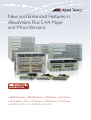
New and Enhanced Features in
AlliedWare Plus 5.4.4 Major
and Minor Versions
» SBx8100 Series » SBx908 Series » x900 Series » x610 Series
» x510 Series » IX5 » x310 Series » x230 Series » x210 Series
» 5.4.4-0.1 » 5.4.4-1.1 » 5.4.4-2.3 » 5.4.4-3.5
Acknowledgments
This product includes software developed by the University of California, Berkeley and its
contributors.
Copyright ©1982, 1986, 1990, 1991, 1993 The Regents of the University of California.
All rights reserved.
This product includes software developed by the OpenSSL Project for use in the OpenSSL
Toolkit. For information about this see www.openssl.org/
Copyright ©1998-2008 The OpenSSL Project. All rights reserved.
This product includes software licensed under the GNU General Public License available
from: www.gnu.org/licenses/gpl2.html
Source code for all GPL licensed software in this product can be obtained from the Allied
Telesis GPL Code Download Center at: www.alliedtelesis.com/support/default.aspx
Allied Telesis is committed to meeting the requirements of the open source licenses
including the GNU General Public License (GPL) and will make all required source code
available.
If you would like a copy of the GPL source code contained in Allied Telesis products, please
send us a request by registered mail including a check for US$15 to cover production and
shipping costs and a CD with the GPL code will be mailed to you.
GPL Code Request
Allied Telesis Labs (Ltd)
PO Box 8011
Christchurch
New Zealand
©2014 Allied Telesis Inc. All rights reserved.
This documentation is subject to change without notice. No part of this publication may
be reproduced, stored in a retrieval system, or transmitted in any form or any means
electronic or mechanical, including photocopying and recording for any purpose other
than the purchaser’s internal use without the written permission of Allied Telesis, Inc.
Allied Telesis, AlliedWare Plus, EPSRing, SwitchBlade, and VCStack are trademarks or
registered trademarks in the United States and elsewhere of Allied Telesis, Inc. Adobe,
Acrobat, and Reader are either registered trademarks or trademarks of Adobe Systems
Incorporated in the United States and/or other countries. Additional brands, names and
products mentioned herein may be trademarks of their respective companies.
Getting the most from this manual
Although you can view this document using Acrobat version 5, to get the best from this
manual, we recommend using Adobe Acrobat Reader version 8 or later. You can download
Acrobat free from www.adobe.com/
ii
New and Enhanced Features in AlliedWare Plus 5.4.4 Major and Minor Versions
Contents
AlliedWare Plus Version 5.4.4-3.5.......................... 1
Introduction .............................................................................................................................................. 2
New Features and Enhancements .................................................................................................... 4
Enhancements to Processing of Next-hop Updates ........................................................... 4
Login Security Enhancements .................................................................................................... 4
VRRPv3 Secondary IPv6 Address................................................................................................ 5
Web Authentication Unmatched Proxy Setting Detection .............................................. 6
Important Considerations Before Upgrading to this Version ................................................. 7
Licensing ............................................................................................................................................. 7
Upgrading a VCStack...................................................................................................................... 7
Forming or extending a VCStack ............................................................................................... 7
ISSU (In-Service Software Upgrade).......................................................................................... 8
AMF software version compatibility ......................................................................................... 8
Upgrading all switches in an AMF network ........................................................................... 8
Licensing this Software Version on an SBx908 Switch .............................................................. 9
Licensing this Software Version on a Control Card for an SBx8100 Series Switch ........11
Installing this Software Version .......................................................................................................13
Installing the GUI...................................................................................................................................15
AlliedWare Plus Version 5.4.4-2.3........................17
Introduction ............................................................................................................................................18
Key New Features and Enhancements..........................................................................................20
Web-Authentication Enhancements ......................................................................................20
Stack-Local-VLANs Enhancements..........................................................................................22
Important Considerations Before Upgrading to this Version ...............................................24
Licensing ...........................................................................................................................................24
Upgrading a VCStack....................................................................................................................24
Forming or extending a VCStack .............................................................................................24
ISSU (In-Service Software Upgrade)........................................................................................25
AMF software version compatibility .......................................................................................25
Upgrading all switches in an AMF network .........................................................................25
Licensing this Software Version on an SBx908 Switch ............................................................26
Licensing this Software Version on a Control Card for an SBx8100 Series Switch ........28
Installing this Software Version .......................................................................................................30
Installing the GUI...................................................................................................................................32
Authentication Commands .............................................................. 35
Stack-Local-VLANs Commands ........................................................ 49
AlliedWare Plus Version 5.4.4-1.1........................51
Introduction ............................................................................................................................................52
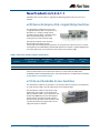
New Products in 5.4.4-1.1...................................................................................................................54
x230 Series Enterprise PoE+ Gigabit Edge Switches.........................................................54
x310 Series Stackable Access Switches..................................................................................54
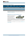
SBx81XS16 Line Card for SBx8100 Series ..............................................................................55
Key New Features and Enhancements..........................................................................................56
Cable Fault Locator .......................................................................................................................56
In-Service Software Upgrade (ISSU)........................................................................................56
AMF Enhancements......................................................................................................................56
New and Enhanced Features in AlliedWare Plus 5.4.4 Major and Minor Versions
iii
Release Licensing...........................................................................................................................57
Important Considerations Before Upgrading to this Version ...............................................58
Licensing ...........................................................................................................................................58
Upgrading a VCStack....................................................................................................................58
Forming or extending a VCStack .............................................................................................58
ISSU (In-Service Software Upgrade)........................................................................................58
AMF software version compatibility .......................................................................................59
Upgrading all switches in an AMF network .........................................................................59
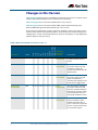
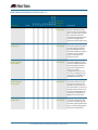
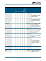
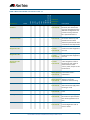
Changes in this Version.......................................................................................................................60
Licensing this Software Version on an SBx908 Switch ............................................................67
Licensing this Software Version on a Control Card for an SBx8100 Series Switch ........69
Installing this Software Version .......................................................................................................71
Installing the GUI...................................................................................................................................73
Cable Fault Locator Introduction..................................................... 75
Introduction to the Cable Fault Locator .......................................................................................76
Capabilities.......................................................................................................................................76
TDR Operating Principles............................................................................................................76
Using the Cable Fault Locator ..........................................................................................................77
Cable Fault Locator Commands ....................................................... 79
ISSU Introduction .............................................................................. 83
Introduction to ISSU.............................................................................................................................84
Operating Requirements ............................................................................................................84
Key Concepts...................................................................................................................................84
ISSU Operation................................................................................................................................85
ISSU Phases ......................................................................................................................................85
Initiating the ISSU Automatic Phase .......................................................................................87
Initiating the ISSU Manual Phase .............................................................................................88
Errors and Recovery ......................................................................................................................88
Automating the ISSU Process Using Triggers.............................................................................90
Related Information .............................................................................................................................91
ISSU Commands ................................................................................ 93
AMF Introduction and Configuration ............................................109
Introduction to AMF.......................................................................................................................... 110
AMF Supported Products and Software Versions .................................................................. 110
Key Benefits of AMF........................................................................................................................... 111
Unified Command-Line ............................................................................................................ 111
Configuration Backup and Recovery ................................................................................... 111
Rolling-Reboot Upgrade .......................................................................................................... 111
Node Provisioning...................................................................................................................... 112
AMF Terminology and Introduction ........................................................................................... 113
AMF Network................................................................................................................................ 113
AMF Nodes .................................................................................................................................... 113
Node Licensing ............................................................................................................................ 113
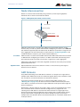
Node Interconnection............................................................................................................... 114
AMF Domains............................................................................................................................... 114
AMF Network Operational Concepts.......................................................................................... 116
Retention and Use of the ‘Manager’ Username............................................................... 116
Working-Set .................................................................................................................................. 116
AMF Restricted-Login................................................................................................................ 117
Loop-Free Data Plane................................................................................................................ 117
Aggregators .................................................................................................................................. 117
iv
New and Enhanced Features in AlliedWare Plus 5.4.4 Major and Minor Versions
VCStacks......................................................................................................................................... 117
AMF External Removable Media ........................................................................................... 117
AMF Interaction with QoS and ACLs.................................................................................... 118
NTP and AMF ................................................................................................................................ 118
Configuring AMF ................................................................................................................................ 119
AMF Tunneling (Virtual Links) ................................................................................................ 125
Verifying the AMF Network ............................................................................................................ 129
Configuring Multiple Nodes at the Same Time: the Unified CLI ....................................... 131
Working-Set Groups .................................................................................................................. 132
Executing Commands on Working-Sets............................................................................. 133
Interactive Commands.............................................................................................................. 136
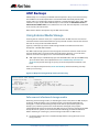
AMF Backups ....................................................................................................................................... 137
Using External Media Storage ................................................................................................ 137
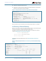
Performing a Manual Backup ................................................................................................. 138
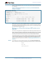
Backing up to Remote Servers ............................................................................................... 142
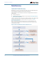
Node Recovery.................................................................................................................................... 144
Automatic Node Recovery....................................................................................................... 144
Restoring a Node to a “Clean” State..................................................................................... 145
Manual Node Recovery............................................................................................................. 146
Node Recovery on VCStacks ................................................................................................... 147
AMF Safe Configuration................................................................................................................... 148
Detecting AMF Safe Configuration Operation................................................................. 148
AMF Safe Configuration Procedures.................................................................................... 148
Undoing an AMF Safe Configuration................................................................................... 149
Rolling-Reboot Firmware Upgrade.............................................................................................. 151
Performing a Rolling-Reboot Upgrade ............................................................................... 153
Node Provisioning ............................................................................................................................. 155
AMF Commands..............................................................................161
Introduction ......................................................................................................................................... 163
AMF Naming Convention ........................................................................................................ 163
AlliedWare Plus Version 5.4.4-0.1......................257
Introduction ......................................................................................................................................... 258
New Products ...................................................................................................................................... 260
x210 Series Enterprise Edge Switches ................................................................................. 260
x510-GPX Series Stackable Gigabit Switches with PoE+ .............................................. 260
x510-28GSX Stackable Fiber Gigabit Switch..................................................................... 261
x510DP-52GTX Stackable Gigabit Switch for Datacenters .......................................... 261
IX5-28GPX High Availability Video Surveillance PoE+ Switch.................................... 262
XEM-24T for x900 Series and SBx908 Switches................................................................ 262
SwitchBlade x8106 Advanced Layer 3+ Chassis Switch ............................................... 262
SBx81CFC960 control card for SBx8100 Series ................................................................ 263
SBx81GT40 line card for SBx8100 Series............................................................................. 263
Key New Features and Enhancements....................................................................................... 265
Allied Telesis Management Framework ............................................................................. 265
VCStack Plus for SBx8100 Series with CFC960 Control Cards..................................... 265
VRF-Lite........................................................................................................................................... 265
BGP4+ ............................................................................................................................................. 266
IPv6 Hardware ACLs................................................................................................................... 266
Authentication Enhancements.............................................................................................. 266
Port Flapping Detection........................................................................................................... 266
Release Licensing........................................................................................................................ 266
Important Considerations Before Upgrading to this Version ............................................ 267
Licensing ........................................................................................................................................ 267
Upgrading a VCStack................................................................................................................. 267
New and Enhanced Features in AlliedWare Plus 5.4.4 Major and Minor Versions
v
Forming or extending a VCStack .......................................................................................... 267
AMF software version compatibility .................................................................................... 268
Upgrading all switches in an AMF network ...................................................................... 268
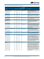
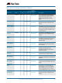
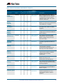
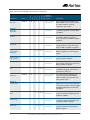
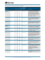
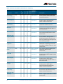
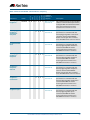
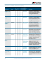
Changes in this Version.................................................................................................................... 269
Licensing this Software Version on an x210 Series, IX5-28GPX, x510 Series,
x610 Series, x900 Series or SBx908 Switch................................................................................ 289
Licensing this Software Version on a Control Card on an SBx8100 Series Switch...... 291
Installing this Software Version .................................................................................................... 293
Installing the GUI................................................................................................................................ 295
vi
New and Enhanced Features in AlliedWare Plus 5.4.4 Major and Minor Versions
AlliedWare Plus Version 5.4.4-3.5
For SwitchBlade x8100 Series, SwitchBlade x908, x900 Series, x610 Series,
x510 Series, IX5-28GPX, x310 Series, x230 Series and x210 Series Switches
Contents
Introduction .............................................................................................................................................. 2
New Features and Enhancements .................................................................................................... 4
Enhancements to Processing of Next-hop Updates ........................................................... 4
Login Security Enhancements..................................................................................................... 4
VRRPv3 Secondary IPv6 Address................................................................................................ 5
Web Authentication Unmatched Proxy Setting Detection .............................................. 6
Important Considerations Before Upgrading to this Version ................................................. 7
Licensing ............................................................................................................................................. 7
Upgrading a VCStack...................................................................................................................... 7
Forming or extending a VCStack................................................................................................ 7
ISSU (In-Service Software Upgrade) .......................................................................................... 8
AMF software version compatibility ......................................................................................... 8
Upgrading all switches in an AMF network............................................................................ 8
Licensing this Software Version on an SBx908 Switch .............................................................. 9
Licensing this Software Version on a Control Card for an SBx8100 Series Switch ........11
Installing this Software Version........................................................................................................13
Installing the GUI...................................................................................................................................15
New and Enhanced Features in AlliedWare Plus 5.4.4 Major and Minor Versions
1
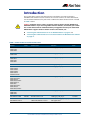
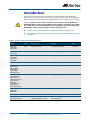
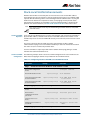
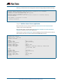
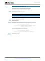
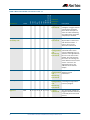
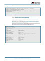
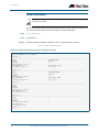
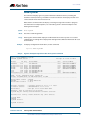
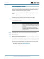
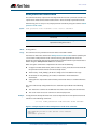
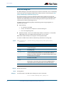
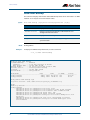
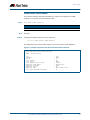
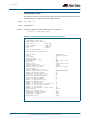
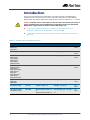
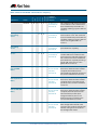
Introduction
This section of this release note describes the new features and enhancements in
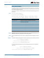
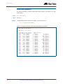
AlliedWare Plus software version 5.4.4-3.5 since version 5.4.4-2.3. For more information,
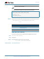
see the Software Reference for your switch. Software file details for this version are listed
in Table 1 below.
Caution: Software version 5.4.4-3.5 requires a release license for the SBx908 and
SBx8100 switches. If you are using either of these switches, ensure that your switch
has a 5.4.4 release license certificate before you upgrade. Contact your authorized
Allied Telesis support center to obtain a license. For details, see:
■
“Licensing this Software Version on an SBx908 Switch” on page 9 and
■
“Licensing this Software Version on a Control Card for an SBx8100 Series Switch”
on page 11.
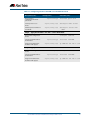
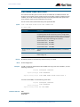
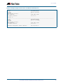
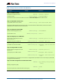
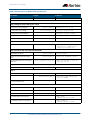
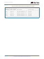
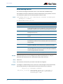
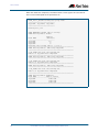
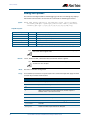
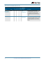
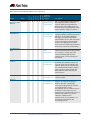
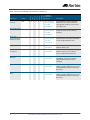
Table 1: Switch models and software file names
Models
Series
Software File
GUI File
Date
x210-9GT
x210-16GT
x210-24GT
x210
x210-5.4.4-3.5.rel
x210-gui_544_08.jar
11/2014
x230-10GP
x230-18GP
x230
x230-5.4.4-3.5.rel
x230-gui_544_02.jar
11/2014
x310-26FT
x310-50FT
x310-26FP
x310-50FP
x310
x310-5.4.4-3.5.rel
x310-gui_544_06.jar
11/2014
IX5-28GPX
IX5
IX5-5.4.4-3.5.rel
IX5-gui_544_09.jar
11/2014
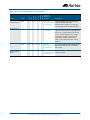
x510-28GTX
x510-52GTX
x510-28GPX
x510-52GPX
x510-28GSX
x510DP-52GTX
x510
x510-5.4.4-3.5.rel
x510-gui_544_10.jar
11/2014
x610-24Ts
x610-24Ts-PoE+
x610-24Ts/X
x610-24Ts/X-PoE+
x610-24SPs/X
x610-48Ts
x610-48Ts-PoE+
x610-48Ts/X
x610-48Ts/X-PoE+
x610
x610-5.4.4-3.5.rel
x610-gui_544_07.jar
11/2014
x900-12XT/S
x900-24XS
x900-24XT
x900
x900-5.4.4-3.5.rel
x900-gui_544_07.jar
11/2014
SwitchBlade x908
SBx908
SBx908-5.4.4-3.5.rel
x900-gui_544_07.jar
11/2014
SwitchBlade x8106
SwitchBlade x8112
SBx8100
SBx81CFC400-5.4.4-3.5.rel
SBx81CFC960-5.4.4-3.5.rel
SBx81CFC400_gui_544_09.jar
Not applicable
11/2014
2
New and Enhanced Features in AlliedWare Plus 5.4.4 Major and Minor Versions
Caution: Using a software version file for the wrong switch model may cause
unpredictable results, including disruption to the network. Information in this release note
is subject to change without notice and does not represent a commitment on the part of
Allied Telesis, Inc. While every effort has been made to ensure that the information
contained within this document and the features and changes described are accurate,
Allied Telesis, Inc. can not accept any type of liability for errors in, or omissions arising
from, the use of this information.
New and Enhanced Features in AlliedWare Plus 5.4.4 Major and Minor Versions
3
New Features and Enhancements
Software version 5.4.4-3.5 includes all the new features that have been added to
AlliedWare Plus since the release of 5.4.4-1.1.
This section summarizes the new features in 5.4.4-3.5. For more information about all
features on the switch, see the Software Reference for your switch. Unless otherwise
stated, all new features and enhancements are available on all switch models running this
version of AlliedWare Plus.
Enhancements to Processing of Next Hop Updates
On SBx8100, SBx908 and x900 series switches, next hop updates are now processed more
efficiently. If your network is designed so that a very large number of routes have the same
next hop, this may improve the responsiveness of time-sensitive protocols such as EPSR
and STP.
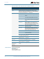
Login Security Enhancements
This software version includes several enhancements to the switch’s login security
settings.
As indicated below, some of these enhancements are only available when the switch is
“locked down” at security level 3. This security level is a bootloader security setting. To set
it, type Ctrl-B during boot-up to enter the bootloader, then type "s" at the bootloader
menu.
The bootloader security settings are available on SBx8100, SBx908, x900, x610, x310 and
x230 Series switches.
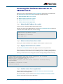
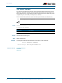
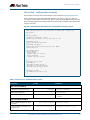
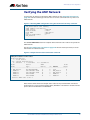
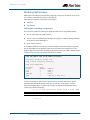
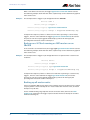
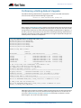
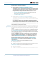
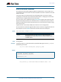
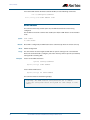
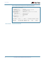
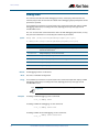
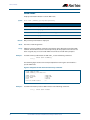
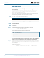
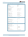
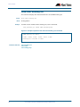
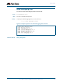
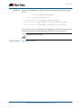
“Last login” message
At login, the switch now displays:
■
■
a "Last login" message, indicating when that user last logged in, and
if the switch’s bootloader is set to security level 3, a "Failed login" message if there
have been any failed login attempts for that user.
These messages are displayed for logins via the console, Telnet or SSH.
The console output looks like this:
x510-D login: aa
Password:
Last login: Mon Oct 13 14:07:32 NZST 2014 on ttyS0
Last failed login: Mon Oct 13 15:21:07 NZST 2014 on ttyS0
There were 2 failed login attempts since the last successful
login.
AlliedWare Plus (TM) 5.4.4 10/13/14 12:59:36
4
New and Enhanced Features in AlliedWare Plus 5.4.4 Major and Minor Versions
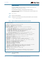
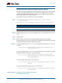
Logging of attempts to set release files
When a user attempts to set a primary or backup release file (using the boot system
command), the switch now sends a failure or success message to the logging system. The
error message has a log severity level of “warning” and the success message has a severity
level of “notice”.
Delay between password attempts
On a switch whose bootloader is set to security level 3, a 4 second gap is now required
between attempts to re-enter a password. This applies for console, Telnet and SSH logins,
and for both local and RADIUS users.
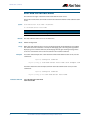
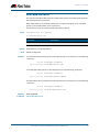
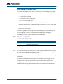
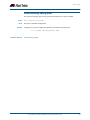
Configurable number of login attempts by SSH
You can now specify the maximum number of SSH authentication attempts that the
switch will allow. The default is 6 attempts. To change this, use the new command:
awplus(config)#ssh server max-auth-tries <1-32>
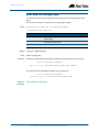
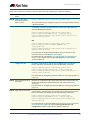
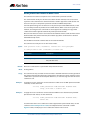
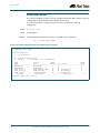
VRRPv3 Secondary IPv6 Address
VRRPv3 now allows users to specify a secondary IPv6 address on an IPv6 VRRP instance.
This enables you to specify a globally-routable address as the default gateway address for
all the hosts on a VLAN.
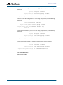
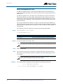
To do this, use the new secondary parameter in the following command:
Syntax
virtual-ipv6 <ipv6-address> [master|backup] [primary|
secondary]
no virtual-ipv6
Mode
Parameter
Description
<ipv6-address>
The IPv6 address of the virtual router, entered in hexadecimal, in
the format X:X::X.X. This is an IPv6 link-local address.
master
Sets the default state of the VRRPv3 router within the Virtual
Router as master. For master, the router must own the Virtual IP
address.
backup
Sets the default state of the VRRPv3 router within the Virtual
Router as backup.
primary
Sets the specified address as the primary IPv6 address. The
primary address must be a link-local IPv6 address.
secondary
Sets the specified address as the secondary IPv6 address.
Normally this would be a globally-routable IPv6 address.
Router Configuration
New and Enhanced Features in AlliedWare Plus 5.4.4 Major and Minor Versions
5
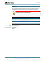
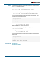
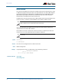
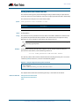
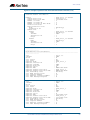
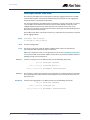
Web Authentication Unmatched Proxy Setting
Detection
By default, AlliedWare Plus Web Authentication intercepts the supplicant’s initial TCP port
80 connection to a web page and sends it the Web Authentication login page. You can
also specify any additional TCP port numbers that the web authentication server is to
intercept by using the auth-web-server intercept-port command. In this way, Web
Authentication can intercept packets going to a proxy server by adding the port number
of the proxy server.
However, when the web authentication switch is in a guest network, the switch does not
know the proxy server’s port number in the supplicant’s proxy setting. To overcome this
limitation, you can now use the new any option in the auth-web-server intercept-port
command to intercept all TCP packets:
awplus(config)#auth-web-server intercept-port any
6
New and Enhanced Features in AlliedWare Plus 5.4.4 Major and Minor Versions
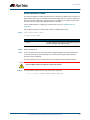
Important Considerations Before
Upgrading to this Version
Licensing
From software version 5.4.4-0.4 onwards, AlliedWare Plus software releases need to be
licensed for SBx908 and SBx8100 switches.
If you are upgrading the software on your SBx908 or SBx8100 switch, please ensure you
have a 5.4.4 license on your switch. To obtain a license, contact your authorized Allied
Telesis support center. You will need to provide the MAC addresses of the switches you
want to license.
For details, see:
■
“Licensing this Software Version on an SBx908 Switch” on page 9 and
■
“Licensing this Software Version on a Control Card for an SBx8100 Series Switch”
on page 11.
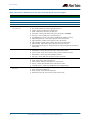
Upgrading a VCStack
This software version supports VCStack “reboot rolling” upgrades. With the reboot
rolling command, you can reduce downtime when upgrading a VCStack.
You can use the reboot rolling command to upgrade to 5.4.4-3.5 from any 5.4.4-1.x
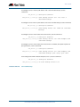
version. The following table shows the process for using it to update from earlier versions.
Upgrading from
How to upgrade using the reboot rolling command
5.4.4-0.x
First upgrade to 5.4.4-1.x, then to 5.4.4-2.x.
5.4.3-x.x
First upgrade to any 5.4.4-0.x version, then to 5.4.4-1.x, then to
5.4.4-2.x.
Forming or extending a VCStack
If you create a VCStack from switches that are running different software versions, autosynchronization ensures that all members will run the same software version when they
boot up.
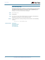
However, auto-synchronization is not supported between all versions of 5.4.4. The
following table lists compatible versions:
If the existing VCStack is running ...
then a new member can join the VCStack if it is running ...
any 5.4.4-0.x version
any 5.4.4-0.x version
5.4.4-1.1 or 5.4.4-1.2
5.4.4-1.1 or 5.4.4-1.2
5.4.4-2.3 or 5.4.4-2.4
5.4.4-2.3 or 5.4.4-2.4
5.4.4-3.5
5.4.4-2.3, 5.4.4-2.4 or 5.4.4-3.5
Before you add a new switch to a stack, make sure the new switch’s version is compatible
with the stack’s version. If the new switch is running an incompatible version, it cannot
join the stack until you have manually upgraded it.
New and Enhanced Features in AlliedWare Plus 5.4.4 Major and Minor Versions
7
ISSU (In-Service Software Upgrade)
This version does not support ISSU: You cannot use ISSU to upgrade to this minor
software version.
AMF software version compatibility
We strongly recommend that all switches in an AMF network run the same software
release.
If this is not possible, switches running this minor version are compatible with:
■
x210 Series switches running version 5.4.4-1.2 (but not earlier versions)
■
other AlliedWare Plus switches running version 5.4.3-2.6 and later or any 5.4.4-x.x
version.
Upgrading all switches in an AMF network
This version supports upgrades across AMF networks.There are two methods for
upgrading firmware on an AMF network:
■
Reboot-rolling, which upgrades and reboots each switch in turn
■
Distribute firmware, which upgrades each switch, but does not reboot them. This lets
you reboot the switches at a minimally-disruptive time.
You can use either of these methods to upgrade to this minor software version.
For x210 Series switches, you can use these methods to upgrade to this version from
5.4.4-1.2, but not from earlier versions.
For other switches, you can use these methods to upgrade to this version from 5.4.3-2.6
and later, or from any 5.4.4-x.x version.
In summary, the process for upgrading firmware on an AMF network is:
1. Copy the release .rel files for each switch family to the media location you intend to
upgrade from (Flash memory, SD card, USB stick etc).
2. Decide which AMF upgrade method is most suitable.
3. Initiate the AMF network upgrade using the selected method. To do this:
a. create a working-set of the switches you want to upgrade
b. enter the command atmf reboot-rolling <location> or atmf distributefirmware <location> where <location> is the location of the .rel files.
c. Check the console messages to make sure that all switches are “release ready”. If
they are, follow the prompts to perform the upgrade.
8
New and Enhanced Features in AlliedWare Plus 5.4.4 Major and Minor Versions
Licensing this Software Version on an
SBx908 Switch
Release licenses are applied with the license certificate command, then validated with
the show license or show license brief commands. Follow these steps:
■
Obtain the MAC address for a switch
■
Obtain a release license for a switch
■
Apply a release license on a switch
■
Confirm release license application
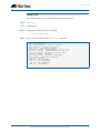
Step 1: Obtain the MAC address for a switch
A release license is tied to the MAC address of the switch.
Switches may have several MAC addresses. Use the show system mac license command
to show the switch MAC address for release licensing:
awplus# show system mac license
MAC address for licensing:
eccd.6d9d.4eed
Step 2: Obtain a release license for a switch
Contact your authorized Allied Telesis support center to obtain a release license.
Step 3: Apply a release license on a switch
Use the license certificate command to apply a release license to your switch.
Note the license certificate file can be stored on internal flash memory, or an external SD
card or a USB drive, or on a TFTP server accessible by SCP or accessible by HTTP protocols.
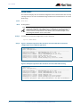
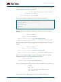
Entering a valid release license changes the console message displayed about licensing:
11:04:56 awplus IMI[1696]: SFL: The current software is not licensed.
awplus#license certificate demo1.csv
A restart of affected modules may be required.
Would you like to continue? (y/n): y
11:58:14 awplus IMI[1696]: SFL: The current software is licensed. Exiting
unlicensed mode.
Stack member 1 installed 1 license
1 license installed.
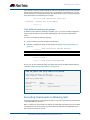
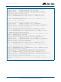
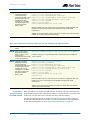
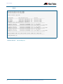
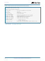
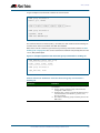
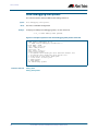
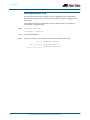
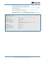
Step 4: Confirm release license application
On a stand-alone switch, use the commands show license or show license brief to
confirm release license application.
On a stacked switch, use the command show license member or show license brief
member to confirm release license application.
New and Enhanced Features in AlliedWare Plus 5.4.4 Major and Minor Versions
9
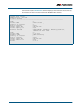
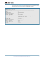
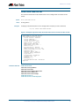
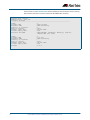
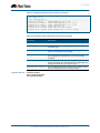
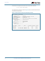
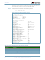
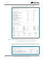
From version 5.4.4, the show license command displays the base feature license and any
other feature and release licenses installed on AlliedWare Plus switches:
awplus# show license
OEM Territory : ATI USA
Software Licenses
-----------------------------------------------------------------------Index
: 1
License name
: Base License
Customer name
: ABC Consulting
Quantity of licenses
: 1
Type of license
: Full
License issue date
: 10-Jul-2014
License expiry date
: N/A
Features included
: EPSR-MASTER, IPv6Basic, MLDSnoop, OSPF-64,
RADIUS-100, RIP, VRRP
Index
License name
Customer name
Quantity of licenses
Type of license
License issue date
License expiry date
Release
10
:
:
:
:
:
:
:
:
2
5.4.4-rl
ABC Consulting
Full
10-Jul-2014
N/A
5.4.4
New and Enhanced Features in AlliedWare Plus 5.4.4 Major and Minor Versions
Licensing this Software Version on a
Control Card for an SBx8100 Series Switch
Release licenses are applied with the license certificate command, then validated with
the show license or show license brief commands. Follow these steps:
■
Obtain the MAC address for a control card
■
Obtain a release license for a control card
■
Apply a release license on a control card
■
Confirm release license application
If your control card is in a stacked chassis, you do not need to perform these steps on each
chassis in the stack, only on the stack master.
If your license certificate contains release licenses for each control card present in a
stacked chassis, entering the license certificate command on the stack master will
automatically apply the release licenses to all the control cards within the stack.
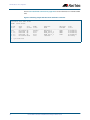
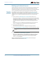
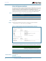
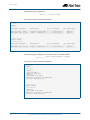
Step 1: Obtain the MAC address for a control card
A release license is tied to the control card MAC address in a chassis.
Chassis may have several MAC addresses. Use the show system mac license command to
show the control card MAC address for release licensing. Note the MAC addresses for each
control card in the chassis. The chassis MAC address is not used for release licensing. Use
the card MAC address for release licensing.
awplus#show system mac license
MAC address for licensing:
Card
MAC Address
-----------------------------------1.5
eccd.6d9e.3312
1.6
eccd.6db3.58e7
Chassis MAC Address eccd.6d7b.3bc2
Step 2: Obtain a release license for a control card
Contact your authorized Allied Telesis support center to obtain a release license.
Step 3: Apply a release license on a control card
Use the license certificate command to apply a release license to each control card
installed in your chassis or stack.
Note the license certificate file can be stored on internal flash memory, a USB drive, or on a
TFTP server accessible by SCP or accessible by HTTP protocols.
New and Enhanced Features in AlliedWare Plus 5.4.4 Major and Minor Versions
11
Entering a valid release license changes the console message displayed about licensing:
11:04:56 awplus IMI[1696]: SFL: The current software is not licensed.
awplus# license certificate demo1.csv
A restart of affected modules may be required.
Would you like to continue? (y/n): y
11:58:14 awplus IMI[1696]: SFL: The current software is licensed. Exiting
unlicensed mode.
Stack member 1 installed 1 license
1 license installed.
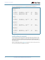
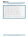
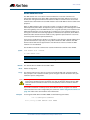
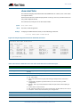
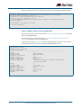
Step 4: Confirm release license application
On a stand-alone chassis, use the commands show license or show license brief to
confirm release license application.
On a stacked chassis, use the command show license member or show license brief
member to confirm release license application.
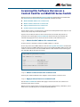
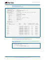
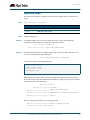
From version 5.4.4, the show license command displays the base feature license and any
other feature and release licenses installed on AlliedWare Plus chassis:
awplus# show license
OEM Territory : ATI USA
Software Licenses
-----------------------------------------------------------------------Index
: 1
License name
: Base License
Customer name
: ABC Consulting
Quantity of licenses
: 1
Type of license
: Full
License issue date
: 10-Jul-2014
License expiry date
: N/A
Features included
: IPv6Basic, LAG-FULL, MLDSnoop, RADIUS-100
Virtual-MAC, VRRP
Index
License name
Customer name
Quantity of licenses
Type of license
License issue date
License expiry date
Release
12
:
:
:
:
:
:
:
:
2
5.4.4-rl
ABC Consulting
Full
10-Jul-2014
N/A
5.4.4
New and Enhanced Features in AlliedWare Plus 5.4.4 Major and Minor Versions
Installing this Software Version
Caution: Software version 5.4.4-2.3 requires a release license for the SBx908 and
SBx8100 switches. If you are using either of these switches, ensure that your switch
has a 5.4.4 release license certificate before you upgrade. Contact your authorized
Allied Telesis support center to obtain a license. For details, see “Licensing this
Software Version on an SBx908 Switch” on page 9 and “Licensing this Software
Version on a Control Card for an SBx8100 Series Switch” on page 11.
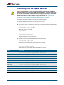
To install and enable this software version, use the following steps:
1. Copy the software version file (.rel) onto your TFTP server.
2. If necessary, delete or move files to create space in the switch’s Flash memory for the
new file. To see the memory usage, use the command:
awplus# show file systems
To list files, use the command:
awplus# dir
To delete files, use the command:
awplus# del <filename>
You cannot delete the current boot file.
3. Copy the new release from your TFTP server onto the switch.
awplus# copy tftp flash
Follow the onscreen prompts to specify the server and file.
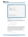
4. Move from Privileged Exec mode to Global Configuration mode, using:
awplus# configure terminal
Then set the switch to reboot with the new software version:
Switch
Command
x210 Series
awplus(config)# boot system x210-5.4.4-3.5.rel
x230 Series
awplus(config)# boot system x230-5.4.4-3.5.rel
x310 Series
awplus(config)# boot system x310-5.4.4-3.5.rel
IX5-28GPX
awplus(config)# boot system IX5-5.4.4-3.5.rel
x510 Series
awplus (config)# boot system x510-5.4.4-3.5.rel
x610 Series
awplus(config)# boot system x610-5.4.4-3.5.rel
x900 Series
awplus(config)# boot system x900-5.4.4-3.5.rel
SBx908
awplus(config)# boot system SBx908-5.4.4-3.5.rel
SBx8100 with CFC400
awplus(config)# boot system SBx81CFC400-5.4.4-3.5.rel
SBx8100 with CFC960
awplus(config)# boot system SBx81CFC960-5.4.4-3.5.rel
New and Enhanced Features in AlliedWare Plus 5.4.4 Major and Minor Versions
13
Return to Privileged Exec mode and check the boot settings, by using the commands:
awplus(config)# exit
awplus# show boot
5. Reboot using the new software version.
awplus# reload
14
New and Enhanced Features in AlliedWare Plus 5.4.4 Major and Minor Versions
Installing the GUI
This section describes how to install and set up the AlliedWare Plus GUI using an SD card, a
USB storage device, or a TFTP server. The version number in the GUI Java applet filename
(.jar) gives the earliest version of the software file (.rel) that the GUI can operate with.
To install and run the AlliedWare Plus GUI requires the following system products and
setup:
■
PC Platform:
Windows XP SP2 and up / Windows Vista SP1 and up
■
Browser: (must support Java Runtime Environment (JRE) version 6)
Microsoft Internet Explorer 7.0 and up / Mozilla Firefox 2.0 and up
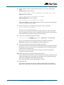
To install the GUI on your switch, use the following steps:
1. Copy to the GUI Java applet file (.jar extension) onto your TFTP server, SD card or USB
storage device.
2. Connect to the switch’s management port, then log into the switch.
3. If necessary, delete or move files to create space in the switch’s Flash memory for the
new file.
To see the memory usage, use the command:
awplus# show file systems
To list files, use the command:
awplus# dir
To delete files, use the command:
awplus# del <filename>
You cannot delete the current boot file.
4. Assign an IP address for connecting to the GUI. Use the commands:
awplus# configure terminal
awplus(config)# interface vlan1
awplus(config-if)#ip address <address>/<prefix-length>
Where <address> is the IP address that you will subsequently browse to when you
connect to the GUI Java applet. For example, to give the switch an IP address of
192.168.2.6, with a subnet mask of 255.255.255.0, use the command:
awplus(config-if)# ip address 192.168.2.6/24
5. If required, configure a default gateway for the switch.
awplus(config-if)# exit
awplus(config)# ip route 0.0.0.0/0 <gateway-address>
Where <gateway-address> is the IP address for your gateway device. You do not need
to define a default gateway if you browse to the switch from within its own subnet.
New and Enhanced Features in AlliedWare Plus 5.4.4 Major and Minor Versions
15
6. Copy the GUI file onto your switch from the TFTP server, SD card, or USB storage
device.
TFTP server: Use the command:
awplus# copy tftp://<server-address>/<filename.jar> flash:/
SD card: use the command:
awplus# copy card:/<filename.jar> flash:/
USB storage device: use the command:
awplus# copy usb:/<filename.jar> flash:/
where <server-address> is the IP address of the TFTP server, and where <filename.jar>
is the filename of the GUI Java applet.
7. Ensure the HTTP service is enabled on your switch. Use the commands:
awplus# configure terminal
awplus(config)# service http
The HTTP service needs to be enabled on the switch before it accepts connections
from a web browser. The HTTP service is enabled by default. However, if the HTTP has
been disabled then you must enable the HTTP service again.
8. Create a user account for logging into the GUI.
awplus(config)# username <username> privilege 15 password
<password>
You can create multiple users to log into the GUI. For information about the
username command, see the AlliedWare Plus Software Reference.
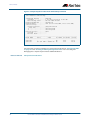
9. Start the Java Control Panel, to enable Java within a browser
On your PC, start the Java Control Panel by opening the Windows Control Panel from
the Windows Start menu. Then enter Java Control Panel in the search field to display
and open the Java Control Panel.
Next, click on the ‘Security’ tab. Ensure the ‘Enable Java content in the browser’
checkbox is selected on this tab.
10. Enter the URL in the Java Control Panel Exception Site List
Click on the ‘Edit Site List’ button in the Java Control Panel dialog Security tab to enter
a URL in the Exception Site List dialog. In the ‘Exception Site List’ dialog, enter the IP
address you configured in Step 4, with a http:// prefix.
After entering the URL click the Add button then click OK.
11. Log into the GUI.
Start a browser and enter the switch’s IP address. The GUI starts up and displays a
login screen. Log in with the username and password specified in the previous step.
16
New and Enhanced Features in AlliedWare Plus 5.4.4 Major and Minor Versions
AlliedWare Plus Version 5.4.4-2.3
For SwitchBlade x8100 Series, SwitchBlade x908, x900 Series, x610 Series,
x510 Series, IX5-28GPX, x310 Series, x230 Series and x210 Series Switches
Contents
Introduction ............................................................................................................................................18
Key New Features and Enhancements..........................................................................................20
Web-Authentication Enhancements ......................................................................................20
Stack-Local-VLANs Enhancements..........................................................................................22
Important Considerations Before Upgrading to this Version ...............................................24
Licensing ...........................................................................................................................................24
Upgrading a VCStack....................................................................................................................24
Forming or extending a VCStack..............................................................................................24
ISSU (In-Service Software Upgrade) ........................................................................................25
AMF software version compatibility .......................................................................................25
Upgrading all switches in an AMF network..........................................................................25
Licensing this Software Version on an SBx908 Switch ............................................................26
Licensing this Software Version on a Control Card for an SBx8100 Series Switch ........28
Installing this Software Version........................................................................................................30
Installing the GUI...................................................................................................................................32
New and Enhanced Features in AlliedWare Plus 5.4.4 Major and Minor Versions
17
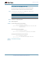
Introduction
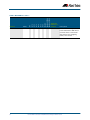
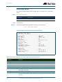
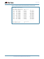
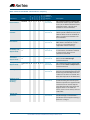
This release note describes the new features and enhancements in AlliedWare Plus
software version 5.4.4-2.3 since version 5.4.4-1.1. For more information, see the Software
Reference for your switch. Software file details for this version are listed in Table 1 below.
Caution: Software version 5.4.4-2.3 requires a release license for the SBx908 and
SBx8100 switches. If you are using either of these switches, ensure that your switch
has a 5.4.4 release license certificate before you upgrade. Contact your authorized
Allied Telesis support center to obtain a license. For details, see:
■
“Licensing this Software Version on an SBx908 Switch” on page 26 and
■
“Licensing this Software Version on a Control Card for an SBx8100 Series Switch”
on page 28.
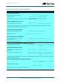
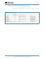
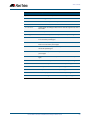
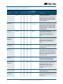
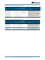
Table 1: Switch models and software file names
Models
Series
Software File
GUI File
Date
x210-9GT
x210-16GT
x210-24GT
x210
x210-5.4.4-2.3.rel
x210-gui_544_06.jar
10/2014
x230-10GP
x230-18GP
x230
x230-5.4.4-2.3.rel
x230-gui_544_02.jar
10/2014
x310-26FT
x310-50FT
x310-26FP
x310-50FP
x310
x310-5.4.4-2.3.rel
x310-gui_544_02.jar
10/2014
IX5-28GPX
IX5
IX5-5.4.4-2.3.rel
IX5-gui_544_07.jar
10/2014
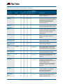
x510-28GTX
x510-52GTX
x510-28GPX
x510-52GPX
x510-28GSX
x510DP-52GTX
x510
x510-5.4.4-2.3.rel
x510-gui_544_07.jar
10/2014
x610-24Ts
x610-24Ts-PoE+
x610-24Ts/X
x610-24Ts/X-PoE+
x610-24SPs/X
x610-48Ts
x610-48Ts-PoE+
x610-48Ts/X
x610-48Ts/X-PoE+
x610
x610-5.4.4-2.3.rel
x610-gui_544_07.jar
10/2014
x900-12XT/S
x900-24XS
x900-24XT
x900
x900-5.4.4-2.3.rel
x900-gui_544_07.jar
10/2014
SwitchBlade x908
SBx908
SBx908-5.4.4-2.3.rel
x900-gui_544_07.jar
10/2014
SwitchBlade x8106
SwitchBlade x8112
SBx8100
SBx81CFC400-5.4.4-2.3.rel
SBx81CFC960-5.4.4-2.3.rel
SBx81CFC400_gui_544_07.jar
Not applicable
10/2014
18
New and Enhanced Features in AlliedWare Plus 5.4.4 Major and Minor Versions
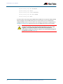
Caution: Using a software version file for the wrong switch model may cause
unpredictable results, including disruption to the network. Information in this release note
is subject to change without notice and does not represent a commitment on the part of
Allied Telesis, Inc. While every effort has been made to ensure that the information
contained within this document and the features and changes described are accurate,
Allied Telesis, Inc. can not accept any type of liability for errors in, or omissions arising
from, the use of this information.
New and Enhanced Features in AlliedWare Plus 5.4.4 Major and Minor Versions
19
Key New Features and Enhancements
Software version 5.4.4-2.3 includes all the new features that have been added to
AlliedWare Plus since the release of 5.4.4-1.1.
This section summarizes the key new features. For more information about all features on
the switch, see the Software Reference for your switch. Unless otherwise stated, all new
features and enhancements are available on all switch models running this version of
AlliedWare Plus.
Web-Authentication Enhancements
The following enhancements have been added to web-authentication.
Custom login page
■
Custom login page
■
External login page
■
Robust web-authentication
You can customize the web-authentication page by changing the web page logo image,
success message, welcome message, and web page title.
The following commands have been introduced for this enhancement.
External login page
■
auth-web-server page logo
■
auth-web-server page sub-title
■
auth-web-server page success-message
■
auth-web-server page title
■
auth-web-server page welcome-message
■
show auth-web-server page
You can use an external login page for web-authentication rather than using the built-in
AlliedWare Plus login page.
The auth-web forward command has been introduced for this enhancement.
Robust webauthentication
20
Web-authentication configuration has been simplified and some limitations have been
removed. For command details, see Authentication Commands in this release note.
■
Previously, you could configure an intercept mode on the web-authentication server
for supplicants (client devices). Now, you no longer need to configure the intercept
mode. Intercept mode is always available and it intercepts HTTP packets but doesn’t
intercept ARP or DNS messages. As a result, the auth-web-server mode command
has been deleted.
■
Previously, you could enable the HTTP redirect feature on every interface on which
web-based port authentication was enabled. Now, the HTTP redirect feature is always
enabled and you cannot disable it. As a result, the auth-web-server http-redirect
command has been deleted.
■
Previously, you needed to register the gateway information when the supplicant was
authorized. Now, the AlliedWare Plus device acts as the default gateway and you no
longer need to add the gateway information. As a result, the auth-web-server
gateway command has been deleted.
New and Enhanced Features in AlliedWare Plus 5.4.4 Major and Minor Versions
■
Previously, you could set the HTTPS port number for the web authentication server.
Now, you no longer need to set the port number and the default port number 443 is
used. As a result, the auth-web-server sslport command has been deleted.
■
The default behavior of web-authentication packet forwarding has changed.
Previously, packet forwarding for port authentication was disabled by default. Now,
ARP, DHCP, DNS forwarding for port authentication are enabled by default. TCP and
UDP forwarding for port authentication are disabled by default. As a result, the
default behavior of the auth-web forward command has been changed.
■
Previously, you could use either HTTP protocol or HTTPS protocol for the web
authentication server. Both HTTP and HTTPS packets were redirected to HTTP server
or HTTPS server. Now, you can use both HTTP protocol and HTTPS protocol. When
both protocols are used, HTTP packet is redirected to HTTP server and HTTPS packet
is redirected to HTTPS server respectively. As a result, the auth-web-server ssl
command has been changed and you can use the hybrid option of this command to
enable both HTTP and HTTPS for the web authentication server.
■
Previously, you could register only HTTP intercept port numbers. Now, you can use
the auth-web-server ssl intercept-port new command to register HTTPS intercept
port numbers when the HTTPS server uses custom port numbers.
■
Previously, you couldn’t assign a hostname to the web authentication server. Now,
you can use the auth-web-server host-name new command to assign a hostname
to the web authentication server.
■
As a result of the enhancements, the output of the show auth-web-server command
has been changed.
■
If you configure a virtual IP address for the web-authentication server by using the
auth-web-server ipaddress command or the auth-web-server dhcp ipaddress
command, you must add a hardware ACL which sends the packets going to the virtual
IP address to the CPU on the web-authentication enabled interfaces. If the hardware
ACL is not set, the web-authentication success page will not appear on the
supplicant’s web browser. For example, if you configure the virtual IP address 1.2.3.4
and web-authentication is enabled on port1.0.1 and port1.0.7, you must add the
hardware filter send-to-cpu ip any 1.2.3.4/32 to port1.0.1 and port1.0.7 as shown in
the following show running-config command output:
…
auth-web-server ipaddress 1.2.3.4
access-list hardware acl-web
send-to-cpu ip any 1.2.3.4/32
!
interface port1.0.1
auth-web enable
access-group acl-web
!
interface port1.0.7
auth-web enable
access-group acl-web
!
New and Enhanced Features in AlliedWare Plus 5.4.4 Major and Minor Versions
21
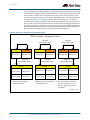
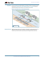
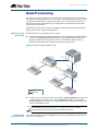
Stack-Local-VLANs Enhancements
Network data VLANs are shared by the stack and use the stack's virtual MAC address.
Consequently only the stack master is able to respond to messages such as ARP or ICMP
requests. One disadvantage of this is that although network administrators can ping the
whole stack to determine its operational status, such pinging will not provide status
information for individual stack members. Stack-local-VLANs provide a solution to this
problem. For command details, see vlan mode stack-local-vlan in this release note.
Note This enhancement exists only on the following stackable switches: x310, x510,
and x610 Series.
Stack-Local-VLAN
Operation
Each stack-local-VLAN belongs to a specific stack member, and uses that stack member’s
physical MAC address, rather than the stack’s virtual MAC address. This enables a stack
member to process stack-local-VLAN traffic directly on its own CPU, even if this is the stack
master.
This strict association of local VLAN, to specific stack member enables network
administrators to ping each stack member individually in order to monitor the health of
the entire stack, on a member-by-member basis.
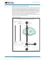
Stack-local-VLANs are especially useful within networks where ping polling is used to
monitor the health of network devices.
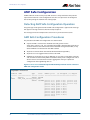
Stack-Local-VLAN
Configuration
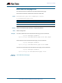
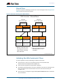
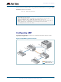
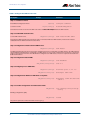
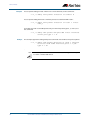
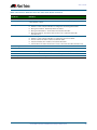
The following example shows a stack-local-VLAN configuration for a two member stack.
Note that overlapping IP subnets are permitted on local VLAN interfaces:
Table 1-1: Configuring Stack-Local-VLANs on a Two Member Stack
Description
Prompt
Command
Step 1. Create the stack-local-VLANs for stack members 1 and 2
Enter global configuration
mode.
awplus#
configure terminal
Enter VLAN database mode.
awplus(config)#
Create the stack-local-VLAN
for stack member 1.
awplus(config-vlan)#
vlan 4001 mode stacklocal-vlan 1
Create the stack-local-VLAN
for stack member 2.
awplus(config-vlan)#
vlan 4001 mode stacklocal-vlan 2
vlan database
Step 2. Apply the access port mode to port 1.0.24
Enter global configuration
mode.
Enter interface
configuration mode for
port 1.0.24.
awplus#
awplus(config)#
configure terminal
interface port1.0.24
Set the port to access
mode.
awplus(config-if)#
switchport mode access
Add this port to member 1’s
local VLAN.
awplus(config-if)#
switchport access vlan
4001
Step 3. Apply the access port mode to port 2.0.24
22
New and Enhanced Features in AlliedWare Plus 5.4.4 Major and Minor Versions
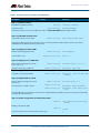
Table 1-1: Configuring Stack-Local-VLANs on a Two Member Stack
Description (cont.)
Enter interface
configuration mode for
port 2.0.24.
Prompt (cont.)
Command (cont.)
awplus(config)#
interface port2.0.24
Set the port to access
mode.
awplus(config-if)#
switchport mode access
Add this port to member 2’s
local VLAN.
awplus(config-if)#
switchport access vlan
4002
Step 4. Apply the IP address 192.168.1.1/24 to VLAN 4001
Enter global configuration
mode.
awplus#
configure terminal
Select local VLAN interface
for member 1
awplus(config)#
interface vlan4001
Assign an IP address that
member 1 will reply to.
awplus(config-if)#
ip address 192.168.1.1/24
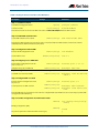
Step 5. Apply the IP address 192.168.1.2/24 to VLAN 4002
Enter global configuration
mode.
awplus#
configure terminal
Select local VLAN interface
for member 2
awplus(config)#
interface vlan4002
Assign an IP address that
member 2 will reply to.
awplus(config-if)#
ip address 192.168.1.2/24
New and Enhanced Features in AlliedWare Plus 5.4.4 Major and Minor Versions
23
Important Considerations Before
Upgrading to this Version
Licensing
From software version 5.4.4-0.4 onwards, AlliedWare Plus software releases need to be
licensed for SBx908 and SBx8100 switches.
If you are upgrading the software on your SBx908 or SBx8100 switch, please ensure you
have a 5.4.4 license on your switch. To obtain a license, contact your authorized Allied
Telesis support center. You will need to provide the MAC addresses of the switches you
want to license.
For details, see:
■
“Licensing this Software Version on an SBx908 Switch” on page 26 and
■
“Licensing this Software Version on a Control Card for an SBx8100 Series Switch”
on page 28.
Upgrading a VCStack
This software version supports VCStack “reboot rolling” upgrades. With the reboot
rolling command, you can reduce downtime when upgrading a VCStack.
You can use the reboot rolling command to upgrade to 5.4.4-2.3 from any 5.4.4-1.x
version. The following table shows the process for using it to update from earlier versions.
Upgrading from
How to upgrade using the reboot rolling command
5.4.4-0.x
First upgrade to 5.4.4-1.x, then to 5.4.4-2.x.
5.4.3-x.x
First upgrade to any 5.4.4-0.x version, then to 5.4.4-1.x, then to
5.4.4-2.x.
Forming or extending a VCStack
If you create a VCStack from switches that are running different software versions, autosynchronization ensures that all members will run the same software version when they
boot up.
However, auto-synchronization is not supported between all versions of 5.4.4. The
following table lists compatible versions:
If the existing VCStack is running ...
then a new member can join the VCStack if it is running ...
any 5.4.4-0.x version
any 5.4.4-0.x version
5.4.4-1.1 or 5.4.4-1.2
5.4.4-1.1 or 5.4.4-1.2
5.4.4-2.3 or 5.4.4-2.4
5.4.4-2.3 or 5.4.4-2.4
Before you add a new switch to a stack, make sure the new switch’s version is compatible
with the stack’s version. If the new switch is running an incompatible version, it cannot
join the stack until you have manually upgraded it.
24
New and Enhanced Features in AlliedWare Plus 5.4.4 Major and Minor Versions
ISSU (In-Service Software Upgrade)
This version does not support ISSU: You cannot use ISSU to upgrade to this minor
software version.
AMF software version compatibility
We strongly recommend that all switches in an AMF network run the same software
release.
If this is not possible, switches running this minor version are compatible with:
■
x210 Series switches running version 5.4.4-1.2 (but not earlier versions)
■
other AlliedWare Plus switches running version 5.4.3-2.6 and later or any 5.4.4-x.x
version.
Upgrading all switches in an AMF network
This version supports upgrades across AMF networks.There are two methods for
upgrading firmware on an AMF network:
■
Reboot-rolling, which upgrades and reboots each switch in turn
■
Distribute firmware, which upgrades each switch, but does not reboot them. This lets
you reboot the switches at a minimally-disruptive time.
You can use either of these methods to upgrade to this minor software version.
For x210 Series switches, you can use these methods to upgrade to this version from
5.4.4-1.2, but not from earlier versions.
For other switches, you can use these methods to upgrade to this version from 5.4.3-2.6
and later, or from any 5.4.4-x.x version.
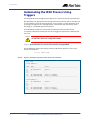
In summary, the process for upgrading firmware on an AMF network is:
1. Copy the release .rel files for each switch family to the media location you intend to
upgrade from (Flash memory, SD card, USB stick etc).
2. Decide which AMF upgrade method is most suitable.
3. Initiate the AMF network upgrade using the selected method. To do this:
a. create a working-set of the switches you want to upgrade
b. enter the command atmf reboot-rolling <location> or atmf distributefirmware <location> where <location> is the location of the .rel files.
c. Check the console messages to make sure that all switches are “release ready”. If
they are, follow the prompts to perform the upgrade.
New and Enhanced Features in AlliedWare Plus 5.4.4 Major and Minor Versions
25
Licensing this Software Version on an
SBx908 Switch
Release licenses are applied with the license certificate command, then validated with
the show license or show license brief commands. Follow these steps:
■
Obtain the MAC address for a switch
■
Obtain a release license for a switch
■
Apply a release license on a switch
■
Confirm release license application
Step 1: Obtain the MAC address for a switch
A release license is tied to the MAC address of the switch.
Switches may have several MAC addresses. Use the show system mac license command
to show the switch MAC address for release licensing:
awplus# show system mac license
MAC address for licensing:
eccd.6d9d.4eed
Step 2: Obtain a release license for a switch
Contact your authorized Allied Telesis support center to obtain a release license.
Step 3: Apply a release license on a switch
Use the license certificate command to apply a release license to your switch.
Note the license certificate file can be stored on internal flash memory, or an external SD
card or a USB drive, or on a TFTP server accessible by SCP or accessible by HTTP protocols.
Entering a valid release license changes the console message displayed about licensing:
11:04:56 awplus IMI[1696]: SFL: The current software is not licensed.
awplus#license certificate demo1.csv
A restart of affected modules may be required.
Would you like to continue? (y/n): y
11:58:14 awplus IMI[1696]: SFL: The current software is licensed. Exiting
unlicensed mode.
Stack member 1 installed 1 license
1 license installed.
Step 4: Confirm release license application
On a stand-alone switch, use the commands show license or show license brief to
confirm release license application.
On a stacked switch, use the command show license member or show license brief
member to confirm release license application.
26
New and Enhanced Features in AlliedWare Plus 5.4.4 Major and Minor Versions
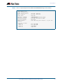
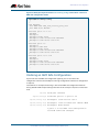
From version 5.4.4, the show license command displays the base feature license and any
other feature and release licenses installed on AlliedWare Plus switches:
awplus# show license
OEM Territory : ATI USA
Software Licenses
-----------------------------------------------------------------------Index
: 1
License name
: Base License
Customer name
: ABC Consulting
Quantity of licenses
: 1
Type of license
: Full
License issue date
: 10-Jul-2014
License expiry date
: N/A
Features included
: EPSR-MASTER, IPv6Basic, MLDSnoop, OSPF-64,
RADIUS-100, RIP, VRRP
Index
License name
Customer name
Quantity of licenses
Type of license
License issue date
License expiry date
Release
:
:
:
:
:
:
:
:
2
5.4.4-rl
ABC Consulting
Full
10-Jul-2014
N/A
5.4.4
New and Enhanced Features in AlliedWare Plus 5.4.4 Major and Minor Versions
27
Licensing this Software Version on a
Control Card for an SBx8100 Series Switch
Release licenses are applied with the license certificate command, then validated with
the show license or show license brief commands. Follow these steps:
■
Obtain the MAC address for a control card
■
Obtain a release license for a control card
■
Apply a release license on a control card
■
Confirm release license application
If your control card is in a stacked chassis, you do not need to perform these steps on each
chassis in the stack, only on the stack master.
If your license certificate contains release licenses for each control card present in a
stacked chassis, entering the license certificate command on the stack master will
automatically apply the release licenses to all the control cards within the stack.
Step 1: Obtain the MAC address for a control card
A release license is tied to the control card MAC address in a chassis.
Chassis may have several MAC addresses. Use the show system mac license command to
show the control card MAC address for release licensing. Note the MAC addresses for each
control card in the chassis. The chassis MAC address is not used for release licensing. Use
the card MAC address for release licensing.
awplus#show system mac license
MAC address for licensing:
Card
MAC Address
-----------------------------------1.5
eccd.6d9e.3312
1.6
eccd.6db3.58e7
Chassis MAC Address eccd.6d7b.3bc2
Step 2: Obtain a release license for a control card
Contact your authorized Allied Telesis support center to obtain a release license.
Step 3: Apply a release license on a control card
Use the license certificate command to apply a release license to each control card
installed in your chassis or stack.
Note the license certificate file can be stored on internal flash memory, a USB drive, or on a
TFTP server accessible by SCP or accessible by HTTP protocols.
28
New and Enhanced Features in AlliedWare Plus 5.4.4 Major and Minor Versions
Entering a valid release license changes the console message displayed about licensing:
11:04:56 awplus IMI[1696]: SFL: The current software is not licensed.
awplus# license certificate demo1.csv
A restart of affected modules may be required.
Would you like to continue? (y/n): y
11:58:14 awplus IMI[1696]: SFL: The current software is licensed. Exiting
unlicensed mode.
Stack member 1 installed 1 license
1 license installed.
Step 4: Confirm release license application
On a stand-alone chassis, use the commands show license or show license brief to
confirm release license application.
On a stacked chassis, use the command show license member or show license brief
member to confirm release license application.
From version 5.4.4, the show license command displays the base feature license and any
other feature and release licenses installed on AlliedWare Plus chassis:
awplus# show license
OEM Territory : ATI USA
Software Licenses
-----------------------------------------------------------------------Index
: 1
License name
: Base License
Customer name
: ABC Consulting
Quantity of licenses
: 1
Type of license
: Full
License issue date
: 10-Jul-2014
License expiry date
: N/A
Features included
: IPv6Basic, LAG-FULL, MLDSnoop, RADIUS-100
Virtual-MAC, VRRP
Index
License name
Customer name
Quantity of licenses
Type of license
License issue date
License expiry date
Release
:
:
:
:
:
:
:
:
2
5.4.4-rl
ABC Consulting
Full
10-Jul-2014
N/A
5.4.4
New and Enhanced Features in AlliedWare Plus 5.4.4 Major and Minor Versions
29
Installing this Software Version
Caution: Software version 5.4.4-2.3 requires a release license for the SBx908 and
SBx8100 switches. If you are using either of these switches, ensure that your switch
has a 5.4.4 release license certificate before you upgrade. Contact your authorized
Allied Telesis support center to obtain a license. For details, see “Licensing this
Software Version on an SBx908 Switch” on page 26 and “Licensing this Software
Version on a Control Card for an SBx8100 Series Switch” on page 28.
To install and enable this software version, use the following steps:
1. Copy the software version file (.rel) onto your TFTP server.
2. If necessary, delete or move files to create space in the switch’s Flash memory for the
new file. To see the memory usage, use the command:
awplus# show file systems
To list files, use the command:
awplus# dir
To delete files, use the command:
awplus# del <filename>
You cannot delete the current boot file.
3. Copy the new release from your TFTP server onto the switch.
awplus# copy tftp flash
Follow the onscreen prompts to specify the server and file.
4. Move from Privileged Exec mode to Global Configuration mode, using:
awplus# configure terminal
Then set the switch to reboot with the new software version:
Switch
Command
x210 Series
awplus(config)# boot system x210-5.4.4-2.3.rel
x230 Series
awplus(config)# boot system x230-5.4.4-2.3.rel
x310 Series
awplus(config)# boot system x310-5.4.4-2.3.rel
IX5-28GPX
awplus(config)# boot system IX5-5.4.4-2.3.rel
x510 Series
awplus (config)# boot system x510-5.4.4-2.3.rel
x610 Series
awplus(config)# boot system x610-5.4.4-2.3.rel
x900 Series
awplus(config)# boot system x900-5.4.4-2.3.rel
SBx908
awplus(config)# boot system SBx908-5.4.4-2.3.rel
SBx8100 with CFC400
awplus(config)# boot system SBx81CFC400-5.4.4-2.3.rel
SBx8100 with CFC960
awplus(config)# boot system SBx81CFC960-5.4.4-2.3.rel
30
New and Enhanced Features in AlliedWare Plus 5.4.4 Major and Minor Versions
Return to Privileged Exec mode and check the boot settings, by using the commands:
awplus(config)# exit
awplus# show boot
5. Reboot using the new software version.
awplus# reload
New and Enhanced Features in AlliedWare Plus 5.4.4 Major and Minor Versions
31
Installing the GUI
This section describes how to install and set up the AlliedWare Plus GUI using an SD card, a
USB storage device, or a TFTP server. The version number in the GUI Java applet filename
(.jar) gives the earliest version of the software file (.rel) that the GUI can operate with.
To install and run the AlliedWare Plus GUI requires the following system products and
setup:
■
PC Platform:
Windows XP SP2 and up / Windows Vista SP1 and up
■
Browser: (must support Java Runtime Environment (JRE) version 6)
Microsoft Internet Explorer 7.0 and up / Mozilla Firefox 2.0 and up
To install the GUI on your switch, use the following steps:
1. Copy to the GUI Java applet file (.jar extension) onto your TFTP server, SD card or USB
storage device.
2. Connect to the switch’s management port, then log into the switch.
3. If necessary, delete or move files to create space in the switch’s Flash memory for the
new file.
To see the memory usage, use the command:
awplus# show file systems
To list files, use the command:
awplus# dir
To delete files, use the command:
awplus# del <filename>
You cannot delete the current boot file.
4. Assign an IP address for connecting to the GUI. Use the commands:
awplus# configure terminal
awplus(config)# interface vlan1
awplus(config-if)#ip address <address>/<prefix-length>
Where <address> is the IP address that you will subsequently browse to when you
connect to the GUI Java applet. For example, to give the switch an IP address of
192.168.2.6, with a subnet mask of 255.255.255.0, use the command:
awplus(config-if)# ip address 192.168.2.6/24
5. If required, configure a default gateway for the switch.
awplus(config-if)# exit
awplus(config)# ip route 0.0.0.0/0 <gateway-address>
Where <gateway-address> is the IP address for your gateway device. You do not need
to define a default gateway if you browse to the switch from within its own subnet.
32
New and Enhanced Features in AlliedWare Plus 5.4.4 Major and Minor Versions
6. Copy the GUI file onto your switch from the TFTP server, SD card, or USB storage
device.
TFTP server: Use the command:
awplus# copy tftp://<server-address>/<filename.jar> flash:/
SD card: use the command:
awplus# copy card:/<filename.jar> flash:/
USB storage device: use the command:
awplus# copy usb:/<filename.jar> flash:/
where <server-address> is the IP address of the TFTP server, and where <filename.jar>
is the filename of the GUI Java applet.
7. Ensure the HTTP service is enabled on your switch. Use the commands:
awplus# configure terminal
awplus(config)# service http
The HTTP service needs to be enabled on the switch before it accepts connections
from a web browser. The HTTP service is enabled by default. However, if the HTTP has
been disabled then you must enable the HTTP service again.
8. Create a user account for logging into the GUI.
awplus(config)# username <username> privilege 15 password
<password>
You can create multiple users to log into the GUI. For information about the
username command, see the AlliedWare Plus Software Reference.
9. Start the Java Control Panel, to enable Java within a browser
On your PC, start the Java Control Panel by opening the Windows Control Panel from
the Windows Start menu. Then enter Java Control Panel in the search field to display
and open the Java Control Panel.
Next, click on the ‘Security’ tab. Ensure the ‘Enable Java content in the browser’
checkbox is selected on this tab.
10. Enter the URL in the Java Control Panel Exception Site List
Click on the ‘Edit Site List’ button in the Java Control Panel dialog Security tab to enter
a URL in the Exception Site List dialog. In the ‘Exception Site List’ dialog, enter the IP
address you configured in Step 4, with a http:// prefix.
After entering the URL click the Add button then click OK.
11. Log into the GUI.
Start a browser and enter the switch’s IP address. The GUI starts up and displays a
login screen. Log in with the username and password specified in the previous step.
New and Enhanced Features in AlliedWare Plus 5.4.4 Major and Minor Versions
33
34
New and Enhanced Features in AlliedWare Plus 5.4.4 Major and Minor Versions
Authentication Commands
Authentication Commands
Contents
auth-web forward .................................................................................................................................36
auth-web-server host-name .............................................................................................................38
auth-web-server login-url..................................................................................................................39
auth-web-server page logo...............................................................................................................40
auth-web-server page sub-title .......................................................................................................41
auth-web-server page success-message......................................................................................42
auth-web-server page title ................................................................................................................43
auth-web-server page welcome-message ..................................................................................44
auth-web-server ssl ..............................................................................................................................45
auth-web-server ssl intercept-port.................................................................................................46
show auth-web-server ........................................................................................................................47
show auth-web-server page .............................................................................................................48
New and Enhanced Features in AlliedWare Plus 5.4.4 Major and Minor Versions
35
Authentication Commands
auth-web forward
This command enables the web authentication packet forwarding feature on the interface
specified. This command also enables ARP forwarding, and adds forwarded packets to the
TCP or UDP port number specified.
Use the no variant of this command disables or deletes the packet forwarding feature on
the interface.
Syntax
auth-web forward {arp|dhcp}
no auth-web forward {arp|dhcp}
auth-web forward [<ip-address>] {dns|tcp <1-65535>|udp <1-65535>}
no auth-web forward <ip-address> {dns|tcp <1-65535>|udp <1-65535>}
Default
Mode
Examples
Parameter
Description
<ip-address>
Enable forwarding to the destination IPv4 address.
arp
Enable forwarding of ARP.
dhcp
Enable forwarding of DHCP (UDP port 67).
dns
Enable forwarding of DNS (UDP port 53).
tcp
Enable forwarding of TCP specified port number.
<1-65535>
TCP Port number.
udp
Enable forwarding of UDP specified port number.
<1-65535>
UDP Port number.
ARP, DHCP and DNS forwarding for port authentication are enabled by default. TCP and
UDP forwarding for port authentication are disabled by default.
Interface Configuration for a static channel, a dynamic (LACP) channel group, or a switch
port.
To enable the ARP forwarding feature on interface port1.0.2, use the following commands:
awplus# configure terminal
awplus(config)# interface port1.0.2
awplus(config-if)# auth-web forward arp
To enable the ARP forwarding feature on auth config-group student, use the following
commands:
awplus# configure terminal
awplus(config)# auth config-group student
awplus(config-auth-group)# auth-web forward arp
36
New and Enhanced Features in AlliedWare Plus 5.4.4 Major and Minor Versions
Authentication Commands
To add the TCP forwarding port 137 on auth config-group student, use the following
commands:
awplus# configure terminal
awplus(config)# auth config-group student
awplus(config-auth-group)# auth-web forward tcp 137
To disable the ARP forwarding feature on auth config-group student, use the following
commands:
awplus# configure terminal
awplus(config)# auth config-group student
awplus(config-auth- no auth-web forward arp
group)#
To delete the TCP forwarding port 137 on auth config-group student, use the following
commands:
awplus# configure terminal
awplus(config)# auth config-group student
awplus(config-auth-group)# no auth-web forward tcp 137
To delete all of TCP forwarding on auth config-group student, use the following
commands:
awplus# configure terminal
awplus(config)# auth config-group student
awplus(config-auth-group)# no auth-web forward tcp
Related Commands
show auth-web
show auth-web interface
show running-config
New and Enhanced Features in AlliedWare Plus 5.4.4 Major and Minor Versions
37
Authentication Commands
auth-web-server host-name
This command assigns a hostname to the web authentication server.
Use the no variant of this command to remove the hostname from the web authentication
server.
Syntax
auth-web-server host-name <hostname>
no auth-web-server host-name
Default
Parameter
Description
<hostname>
URL string of the hostname
The web authentication server has no hostname.
Mode
Global Configuration
Usage
When the web authentication server uses HTTPS protocol, the web browser will validate
the certificate. If the certificate is invalid, the web page gives a warning message before
displaying server content. However, the web page will not give warning message if the
server has a hostname same as the one stored in the installed certificate.
Examples
To set the auth.example.com as the hostname of the web authentication server, use the
commands:
awplus# configure terminal
awplus(config)# auth-web-server host-name auth.example.com
To remove hostname auth.example.com from the web authentication server, use the
commands:
awplus# configure terminal
awplus(config)# no auth-web-server host-name
Related Commands
38
aaa authentication auth-web
auth-web enable
New and Enhanced Features in AlliedWare Plus 5.4.4 Major and Minor Versions
Authentication Commands
auth-web-server login-url
This command sets the web-authentication login page URL.
Use the no variant of this command to delete the set URL.
Syntax
auth-web-server login-url <URL>
no auth-web-server login-url
Default
Mode
Examples
Parameter
Description
<URL>
Set login page URL
The built-in login page is set by default.
Global Configuration
To set http://example.com/login.html as the login page, use the commands:
awplus# configure terminal
awplus(config)# auth-web-server login-url http://
example.com/login.html
To unset the login page URL, use the commands:
awplus# configure terminal
awplus(config)# no auth-web-server login-url
Validation
Commands
show running-config
New and Enhanced Features in AlliedWare Plus 5.4.4 Major and Minor Versions
39
Authentication Commands
auth-web-server page logo
This command sets the type of logo that will be displayed on the web authentication
page.
Use the no variant of this command to set the logo type to auto.
Syntax
auth-web-server page logo {auto|default|hidden}
no auth-web-server page logo
Default
Mode
Examples
Parameter
Description
auto
Display the custom logo if installed; otherwise display the
default logo
default
Display the default logo
hidden
Hide the logo
Logo type is auto by default.
Global Configuration
To display the default logo with ignoring installed custom logo, use the commands:
awplus# configure terminal
awplus(config)# auth-web-server page logo default
To set back to the default logo type auto, use the commands:
awplus# configure terminal
awplus(config)# no auth-web-server page logo
Validation
Commands
40
show auth-web-server page
New and Enhanced Features in AlliedWare Plus 5.4.4 Major and Minor Versions
Authentication Commands
auth-web-server page sub-title
This command sets the custom sub-title on the web authentication page.
Use the no variant of this command to reset the sub-title to its default.
Syntax
auth-web-server page sub-title {hidden|text <sub-title>}
no auth-web-server page sub-title
Default
Mode
Examples
Parameter
Description
hidden
Hide the sub-title
<sub-title>
Text string of the sub-title
"Allied-Telesis" is displayed by default.
Global Configuration
To set the custom sub-title, use the commands:
awplus# configure terminal
awplus(config)# auth-web-server page sub-title text Web
Authentication
To hide the sub-title, use the commands:
awplus# configure terminal
awplus(config)# auth-web-server page sub-title hidden
To change back to the default title, use the commands:
awplus# configure terminal
awplus(config)# no auth-web-server page sub-title
Validation
Commands
show auth-web-server page
New and Enhanced Features in AlliedWare Plus 5.4.4 Major and Minor Versions
41
Authentication Commands
auth-web-server page success-message
This command sets the success message on the web-authentication page.
Use the no variant of this command to remove the success message.
Syntax
auth-web-server page success-message text <success-message>
no auth-web-server page success-message
Default
Mode
Examples
Parameter
Description
<success-message>
Text string of the success message
No success message is set by default.
Global Configuration
To set the success message on the web-authentication page, use the commands:
awplus# configure terminal
awplus(config)# auth-web-server page success-message text
Your success message
To unset the success message on the web-authentication page, use the commands:
awplus# configure terminal
awplus(config)# no auth-web-server page success-message
Validation
Commands
42
show auth-web-server page
New and Enhanced Features in AlliedWare Plus 5.4.4 Major and Minor Versions
Authentication Commands
auth-web-server page title
This command sets the custom title on the web authentication page.
Use the no variant of this command to remove the custom title.
Syntax
auth-web-server page title {hidden|text <title>}
no auth-web-server page title
Default
Mode
Examples
Parameter
Description
hidden
Hide the title
<title>
Text string of the title
“Web Access Authentication Gateway” is displayed by default.
Global Configuration
To set the custom title on the web authentication page, use the commands:
awplus# configure terminal
awplus(config)# auth-web-server page title text Login
To hide the title on the web authentication page, use the commands:
awplus# configure terminal
awplus(config)# auth-web-server page title hidden
To unset the custom title on the web authentication page, use the commands:
awplus# configure terminal
awplus(config)# no auth-web-server page title
Validation
Commands
show auth-web-server page
New and Enhanced Features in AlliedWare Plus 5.4.4 Major and Minor Versions
43
Authentication Commands
auth-web-server page welcome-message
This command sets the welcome message on the web-authentication page.
Use the no variant of this command to remove the welcome message.
Syntax
auth-web-server page welcome-message text <welcome-message>
no auth-web-server page welcome-message
Default
Mode
Examples
Parameter
Description
<welcome-message>
Text string of the welcome message
No welcome message is set by default.
Global Configuration
To set the welcome message on the web-authentication page, use the commands:
awplus# configure terminal
awplus(config)# auth-web-server page welcome-message text
Your welcome message
To remove the welcome message on the web-authentication page, use the commands:
awplus# configure terminal
awplus(config)# no auth-web-server page welcome-message
Validation
Commands
44
show auth-web-server page
New and Enhanced Features in AlliedWare Plus 5.4.4 Major and Minor Versions
Authentication Commands
auth-web-server ssl
This command enables HTTPS protocol or both HTTP protocol and HTTPS protocol for the
web authentication server feature.
When both protocols are enabled, HTTP packet is redirected to HTTP server and HTTPS
packet is redirected to HTTPS server respectively.
Use the no variant of this command to disable HTTPS protocol.
Syntax
auth-web-server ssl [hybrid]
no auth-web-server ssl
Default
Mode
Examples
Parameter
Description
hybrid
Enable both HTTP protocol and HTTPS protocol
HTTP protocol is enabled by default.
Global Configuration
To enable HTTPS functionality for the web authentication server feature, use the following
commands:
awplus# configure terminal
awplus(config)# auth-web-server ssl
To enable both HTTP protocol and HTTPS protocol, use the following commands:
awplus# configure terminal
awplus(config)# auth-web-server hybrid
To disable HTTPS functionality for the web authentication server feature, use the following
commands:
awplus# configure terminal
awplus(config)# no auth-web-server ssl
Validation
Commands
show auth-web
show auth-web-server
New and Enhanced Features in AlliedWare Plus 5.4.4 Major and Minor Versions
45
Authentication Commands
auth-web-server ssl intercept-port
Use this command to register HTTPS intercept port numbers when the HTTPS server uses
custom port number (not TCP port number 443).
Note that you need to use the auth-web-server intercept-port command to register HTTP
intercept port numbers.
Use the no variant of this command to delete registered port number.
Syntax
auth-web-server ssl intercept-port <1-65535>
no auth-web-server ssl intercept-port <1-65535>
Default
Mode
Examples
Parameter
Description
<1-65535>
TCP port number in the range from 1 through 65535
443/TCP is registered by default.
Global Configuration
To register HTTPS port number 3128, use the commands:
awplus# configure terminal
awplus(config)# auth-web-server ssl intercept-port 3128
To delete HTTPS port number 3128, use the commands:
awplus# configure terminal
awplus(config)# no auth-web-server ssl intercept-port 3128
Validation
Commands
Related Commands
46
show auth-web-server
auth-web-server intercept-port
New and Enhanced Features in AlliedWare Plus 5.4.4 Major and Minor Versions
Authentication Commands
show auth-web-server
This command shows the web authentication server configuration and status on the
switch.
Syntax
Mode
Examples
show auth-web-server
Privileged Exec
To display web authentication server configuration and status, use the command:
awplus# show auth-web-server
Figure 1: Example output from the show auth-web-server command on the console.
awplus#show auth-web-server
Web authentication server
Server status: enabled
Server address: -Server Host-Name: -Server protocol: HTTP
DHCP server: disabled
DHCP lease time: 20
DHCP WPAD option URL: -HTTP Port No: -Certification: default
HTTP Intercept Port No: 80
HTTPS Intercept Port No: 443
Redirect URL: -Redirect delay time: 5
Session keep: disabled
Login URL: -PingPolling: disabled
PingInterval: 30
Timeout: 1
FailCount: 5
ReauthTimerRefresh: disabled
awplus#
Related Commands
auth-web forward
auth-web-server ipaddress
auth-web-server port
auth-web-server redirect-delay-time
auth-web-server redirect-url
auth-web-server session-keep
auth-web-server ssl
auth-web-server ssl intercept-port
New and Enhanced Features in AlliedWare Plus 5.4.4 Major and Minor Versions
47
Authentication Commands
show auth-web-server page
This command displays the web-authentication page configuration and status.
Syntax
Mode
Examples
show auth-web-server page
Privileged Exec
To show the web-authentication page information, use the command:
awplus# show auth-web-server page
Figure 2: Example output from the show auth-web-server page command on the
console.
awplus#show auth-web-server page
Web authentication page
Logo: auto
Title: default
Sub-Title: Web Authentication
Welcome message: Your welcome message
Success message: Your success message
Related Commands
48
auth-web forward
auth-web-server page logo
auth-web-server page sub-title
auth-web-server page success-message
auth-web-server page title
auth-web-server page welcome-message
New and Enhanced Features in AlliedWare Plus 5.4.4 Major and Minor Versions
Stack-Local-VLANs Commands
Stack-Local-VLANs Commands
Contents
vlan mode stack-local-vlan................................................................................................................50
New and Enhanced Features in AlliedWare Plus 5.4.4 Major and Minor Versions
49
Stack-Local-VLANs Commands
vlan mode stack-local-vlan
This command enables you to create stack-local-VLANs and use ICMP to monitor and
diagnose issues within specific members of the stack. When a VLAN is added using this
method, all its traffic will be trapped to and processed by the CPU of the specific local
stack member, rather than the CPU of the stack master.
The no variant of this command destroys the specified VLAN.
Syntax
vlan <vid> mode stack-local-vlan <member-id>
no vlan <vid>
Parameter
Description
<vid>
The VID of the VLAN to be created in the range 2-4094. We
recommend that the first stack-local-vlan be assigned the
number 4001 for the first stack member, then incremented
by one for each stack member. So a stack of four members
would be assigned the following VID numbers:
stack member one
VID 4001
stack member two
VID 4002
stack member three VID 4003
stack member four
VID 4004
mode stack-local- Specifies that the new VLAN will function as a stack-localvlan
VLAN.
<member-id>
Default
Mode
Examples
Specifies the new stack member ID. Enter a decimal number
in the range 1-8.
By default, VLANs are automatically enabled as they are added.
VLAN Configuration
To add a stack-local-VLAN with the VID of 4002 and assign it to stack member 2, use the
following commands:
awplus# configure terminal
awplus(config)# vlan database
awplus(config-vlan)# vlan 4002 mode stack-local-vlan 2
To remove VLAN 4002, use the following commands:
awplus# configure terminal
awplus(config)# vlan database
awplus(config-vlan)# no vlan 4002
Related Commands
50
mtu
vlan database
show vlan
New and Enhanced Features in AlliedWare Plus 5.4.4 Major and Minor Versions
AlliedWare Plus Version 5.4.4-1.1
For SwitchBlade x8100 Series, SwitchBlade x908, x900 Series, x610 Series,
x510 Series, IX5-28GPX, x310 Series, x230 Series, and x210 Series Switches
Contents
Introduction ............................................................................................................................................52
New Products in 5.4.4-1.1...................................................................................................................54
x230 Series Enterprise PoE+ Gigabit Edge Switches.........................................................54
x310 Series Stackable Access Switches..................................................................................54
SBx81XS16 Line Card for SBx8100 Series ..............................................................................55
Key New Features and Enhancements..........................................................................................56
Cable Fault Locator .......................................................................................................................56
In-Service Software Upgrade (ISSU) ........................................................................................56
AMF Enhancements ......................................................................................................................56
Release Licensing...........................................................................................................................57
Important Considerations Before Upgrading to this Version ...............................................58
Licensing ...........................................................................................................................................58
Upgrading a VCStack....................................................................................................................58
Forming or extending a VCStack..............................................................................................58
ISSU (In-Service Software Upgrade) ........................................................................................58
AMF software version compatibility .......................................................................................59
Upgrading all switches in an AMF network..........................................................................59
Changes in this Version.......................................................................................................................60
Licensing this Software Version on an SBx908 Switch ............................................................67
Licensing this Software Version on a Control Card for an SBx8100 Series Switch ........69
Installing this Software Version........................................................................................................71
Installing the GUI...................................................................................................................................73
New and Enhanced Features in AlliedWare Plus 5.4.4 Major and Minor Versions
51
Introduction
This release note describes the new features and enhancements in AlliedWare Plus
software version 5.4.4-1.1 since version 5.4.4-0.1. For more information, see the Software
Reference for your switch. Software file details for this version are listed in Table 1 below.
Caution: Software version 5.4.4-1.1 requires a release license for the SBx908 and
SBx8100 switches. If you are using either of these switches, ensure that your switch
has a 5.4.4 release license certificate before you upgrade. Contact your authorized
Allied Telesis support center to obtain a license. For details, see:
■
“Licensing this Software Version on an SBx908 Switch” on page 67 and
■
“Licensing this Software Version on a Control Card for an SBx8100 Series Switch”
on page 69.
Table 1: Switch models and software file names
Models
Series
Software File
GUI File
Date
x210-9GT
x210-16GT
x210-24GT
x210
x210-5.4.4-1.1.rel
x210-gui_544_06.jar
07/2014
x230-10GP
x230-18GP
x230
x230-5.4.4-1.1
Not applicable
07/2014
x310-26FT
x310-50FT
x310-26FP
x310-50FP
x310
x310-5.4.4-1.1.rel
x310-gui_544_02.jar
07/2014
IX5-28GPX
IX5
IX5-5.4.4-1.1.rel
IX5-gui_544_07.jar
07/2014
x510-28GTX
x510-52GTX
x510-28GPX
x510-52GPX
x510-28GSX
x510DP-52GTX
x510
x510-5.4.4-1.1.rel
x510-gui_544_07.jar
07/2014
x610-24Ts
x610-24Ts-PoE+
x610-24Ts/X
x610-24Ts/X-PoE+
x610-24SPs/X
x610-48Ts
x610-48Ts-PoE+
x610-48Ts/X
x610-48Ts/X-PoE+
x610
x610-5.4.4-1.1.rel
x610-gui_544_07.jar
07/2014
x900-12XT/S
x900-24XS
x900-24XT
x900
x900-5.4.4-1.1.rel
x900-gui_544_07.jar
07/2014
SwitchBlade x908
SBx908
SBx908-5.4.4-1.1.rel
x900-gui_544_07.jar
07/2014
SwitchBlade x8106
SwitchBlade x8112
SBx8100
SBx81CFC400-5.4.4-1.1.rel
SBx81CFC960-5.4.4-1.1.rel
SBx81CFC400_gui_544_07.jar
Not applicable
07/2014
52
New and Enhanced Features in AlliedWare Plus 5.4.4 Major and Minor Versions
Caution: Using a software version file for the wrong switch model may cause
unpredictable results, including disruption to the network. Information in this release note
is subject to change without notice and does not represent a commitment on the part of
Allied Telesis, Inc. While every effort has been made to ensure that the information
contained within this document and the features and changes described are accurate,
Allied Telesis, Inc. can not accept any type of liability for errors in, or omissions arising
from, the use of this information.
New and Enhanced Features in AlliedWare Plus 5.4.4 Major and Minor Versions
53
New Products in 5.4.4-1.1
AlliedWare Plus version 5.4.4-1.1 supports the following products that are new since
5.4.4-0.1.
x230 Series Enterprise PoE+ Gigabit Edge Switches
The Allied Telesis x230-GP Series of Layer
2+ Gigabit switches offer an impressive set
of features in a compact design. Power
over Ethernet Plus (PoE+) capability makes
them ideal for powering access and
security devices at the network edge.
Allied Telesis x230-GP Series switches
provide optimal performance for
connecting and remotely powering wireless access points, IP video surveillance cameras,
and IP phones. The x230-10GP and x230-18GP provide 8 or 16 PoE+-capable Gigabit ports,
and 2 SFP uplinks, for secure powered connectivity at the network edge.
Table 2: x230 Series models and port specifications
10/100/1000T (RJ-45)
Copper Ports
100/1000X SPF
Ports
PoE Capable
Ports
Switching
Fabric
Forwarding
Rate
AT-x230-10GP
8
2
8
20 Gbps
14.9 Mpps
AT-x230-18GP
16
2
16
36 Gbps
26.8 Mpps
Product
For more information on the x230 Series switches, see the x230 Series Data Sheet,
Installation Guide and Software Reference. These documents are available from our website
at alliedtelesis.com/switches/x230
x310 Series Stackable Access Switches
The Allied Telesis x310 Series stackable access switches offer an impressive set of features
in a high-value package, ideal for applications at the network edge.
The Allied Telesis x310 Series provide a high
performing and scalable access solution for
today’s networks. With a choice of 24-port and
48-port 10/100BASE-T versions with Gigabit
uplinks, Power over Ethernet (PoE), plus the
ability to stack up to four units, the x310 Series
is perfect for demanding applications at the
edge of enterprise networks.
54
New and Enhanced Features in AlliedWare Plus 5.4.4 Major and Minor Versions
Table 3: x310 Series models and port specifications
Product
10/100BASET (RJ-45)
Copper Ports
100/1000
Combo
Uplink Ports
1 Gigabit
Stacking
Ports
PoE Capable
Ports
Switching
Capacity
Forwarding
Rate
AT-x310-26FT
24
2
2
-
12.8 Gbps
6.5 Mpps
AT-x310-50FT
48
2
2
-
17.6 Gbps
10.1 Mpps
AT-x310-26FP
24
2
2
24
12.8 Gbps
6.5 Mpps
AT-x310-50FP
48
2
2
48
17.6 Gbps
10.1 Mpps
For more information on the x310 Series switches, see the x310 Series Data Sheet,
Installation Guide and Software Reference. These documents are available from our website
at alliedtelesis.com/switches/x310
SBx81XS16 Line Card for SBx8100 Series
The SBx81XS16 line card provides 16 x 10
Gigabit ports, enabling high-speed
backbone connectivity from the core
chassis to distribution devices.
The ability to partner 10 Gigabit Ethernet
with Allied Telesis EPSRing™ (Ethernet
Protection Switched Ring) technology allows the deployment of a high-speed distributed
network solution. Failover in a little as 50ms prevents a node or link failure from affecting
the customer experience, even with demanding applications such as IP telephony and
video monitoring.
For more information on the SBx81XS16 line card, see our website at alliedtelesis.com/
switches/sbx8100.
New and Enhanced Features in AlliedWare Plus 5.4.4 Major and Minor Versions
55
Key New Features and Enhancements
Software version 5.4.4-1.1 includes all the new features that have been added to
AlliedWare Plus since the release of 5.4.4-0.1.
This section summarizes the key new features. For a list of all new and enhanced features
and commands, see “Changes in this Version” on page 60. For more information about
all features on the switch, see the Software Reference for your switch. Unless otherwise
stated, all new features and enhancements are available on all switch models running this
version of AlliedWare Plus.
Cable Fault Locator
The Cable Fault Locator (CFL) is a cable diagnostic tool for copper (but not fiber) cables.
You can select a port and the CFL will display, for that port, connection status or faults that
exist in either the connected cable or in its terminations. The CFL operates using a
technology known as Time Domain Reflectometry (TDR) to test all four pairs of wires
inside the cable.
CFL is now supported on the x510 and x510-DP Series switches.
For more information see “Cable Fault Locator Introduction” on page 75 and “Cable
Fault Locator Commands” on page 79.
In-Service Software Upgrade (ISSU)
ISSU is available on standalone SBx8100 Series switches with dual CFC960 control cards,
and on switches using VCStack Plus to create a single virtual unit out of two chassis (where
each chassis has a pair of CFC960 control cards). ISSU allows you to upgrade the software
release running on the CFCs with no disruption to network traffic passing through the
chassis.
AMF Enhancements
Allied Telesis Management Framework (AMF) is a sophisticated suite of management tools
that provides a simplified approach to network management. Since its initial release in
software version 5.4.3-1.4, AMF has been continually enhanced with features to increase
its versatility. The latest enhancements are described below.
56
Backup to remote
file server
You can now choose to store your switch’s backup data on a remote backup server rather
than on the Master node’s external media. The server is used for both backup and
recovery. Each AMF master can support up to two remote file servers, which are mounted
on the Master's file system.
Recovery progress
LED indication
This feature displays the recovery status during automatic recovery. Two distinct flash
patterns indicate the different possible states during node recovery: “node recovery in
progress” and “node recovery failed”. You can use a new command (atmf recover led-off )
during a recovery to turn off the progress indication and return the port LEDs to their
normal running state.
New and Enhanced Features in AlliedWare Plus 5.4.4 Major and Minor Versions
Node provisioning
Node cleaning
You can now pre-configure, or provision, a port for a future node before it is added to the
network. A provisioned node can be created as a new unique entity, or can be cloned
using the backup data from an existing node. When you add the new node to the
provisioned port in the AMF network, its configuration is automatically loaded from the
information stored in the backup media, with no further effort from you.
A clean device is one that has had its previous release and configuration components
removed. Thanks to the new atmf cleanup command you can now easily return a used
switch to its original “out-of-the-box” state.
This process of cleaning is required when replacing a device with one that has been used
previously and still retains components of its previous configuration. Once you have
cleaned a switch, you can connect it to your AMF network and know that automatic node
recovery will start effortlessly.
Release Licensing
From software version 5.4.4-0.4 onwards, AlliedWare Plus software release licenses are
needed for SBx908 and SBx8100 switches.
If you are upgrading the software on your SBx908 or SBx8100 switch, please ensure you
have a 5.4.4 license on your switch. To obtain a license, contact your authorized Allied
Telesis support center. You will need to provide the MAC addresses of the switches you
want to license. For details, see:
■
“Licensing this Software Version on an SBx908 Switch” on page 67 and
■
“Licensing this Software Version on a Control Card for an SBx8100 Series Switch”
on page 69.
New and Enhanced Features in AlliedWare Plus 5.4.4 Major and Minor Versions
57
Important Considerations Before
Upgrading to this Version
Licensing
From software version 5.4.4-0.4 onwards, AlliedWare Plus software releases need to be
licensed for the SBx908 and SBx8100 switches.
If you are upgrading the software on your SBx908 or SBx8100 switch, please ensure you
have a 5.4.4 license on your switch. To obtain a license, contact your authorized Allied
Telesis support center. You will need to provide the MAC addresses of the switches you
want to license.
For details, see:
■
“Licensing this Software Version on an SBx908 Switch” on page 67 and
■
“Licensing this Software Version on a Control Card for an SBx8100 Series Switch”
on page 69.
Upgrading a VCStack
This software version supports VCStack “reboot rolling” upgrades. With the reboot
rolling command, you can reduce downtime when upgrading a VCStack.
You can use the reboot rolling command to upgrade to 5.4.4-1.1 from any 5.4.4-0.x
version.
However, if you want to use the reboot rolling command to upgrade from any 5.4.3-x.x
version to 5.4.4-1.1, you must upgrade to 5.4.4-0.x first.
Forming or extending a VCStack
If you create a VCStack from switches that are running different software versions, autosynchronization ensures that all members will run the same software version when they
boot up.
However, auto-synchronization is not supported between all versions of 5.4.4. The
following table lists compatible versions:
If the existing VCStack is running ...
then a new member can join the VCStack if it is running ...
any 5.4.4-0.x version
any 5.4.4-0.x version
5.4.4-1.1 or 5.4.4-1.2
5.4.4-1.1 or 5.4.4-1.2
Before you add a new switch to a stack, make sure the new switch’s version is compatible
with the stack’s version. If the new switch is running an incompatible version, it cannot
join the stack until you have manually upgraded it.
ISSU (In-Service Software Upgrade)
This software version does not support ISSU: You cannot use ISSU to upgrade to this
minor software version.
58
New and Enhanced Features in AlliedWare Plus 5.4.4 Major and Minor Versions
AMF software version compatibility
We strongly recommend that all switches in an AMF network run the same software
release.
If this is not possible, switches running this minor version are compatible with switches
running version 5.4.3-2.6 and later, or any 5.4.4-x.x version.
Upgrading all switches in an AMF network
This version supports upgrades across AMF networks.There are two methods for
upgrading firmware on an AMF network:
■
Reboot-rolling, which upgrades and reboots each switch in turn
■
Distribute firmware, which upgrades each switch, but does not reboot them. This lets
you reboot the switches at a minimally-disruptive time.
You can use either of these methods to upgrade to this minor software version.
You can use these methods to upgrade to this version from 5.4.3-2.6 and later, or from any
5.4.4-0.x version.
In summary, the process for upgrading firmware on an AMF network is:
1. Copy the release .rel files for each switch family to the media location you intend to
upgrade from (Flash memory, SD card, USB stick etc).
2. Decide which AMF upgrade method is most suitable.
3. Initiate the AMF network upgrade using the selected method. To do this:
a. create a working-set of the switches you want to upgrade
b. enter the command atmf reboot-rolling <location> or atmf distributefirmware <location> where <location> is the location of the .rel files.
c. Check the console messages to make sure that all switches are “release ready”. If
they are, follow the prompts to perform the upgrade.
New and Enhanced Features in AlliedWare Plus 5.4.4 Major and Minor Versions
59
Changes in this Version
Table 4 on page 60 lists all new and modified commands in this version and shows which
chapter of the Software References has details of each command.
Table 5 on page 65 lists new and modified features in this version.
Table 6 on page 66 lists new and modified SNMP (Simple Network Management
Protocol) MIBs (Management Information Bases) in this version.
If your existing configurations include commands modified or deprecated in this version
(see the Status column in the following tables), check whether you need to modify these
configurations. For full command descriptions, modes and examples, see the appropriate
Software Reference for your switch.
Command
Status
x210
x230
x310
IX5
x510
x610
x900
SBx908
SBx8100 CFC400
SBx8100 CFC960
Table 4: New and modified commands in 5.4.4-1.1
Software
Reference
Chapter
Description
atmf backup delete New
N N N N N Y N Y Y Y AMF
Commands
This command removes a
backup file from external
media.
atmf backup server New
N N N N N Y N Y Y Y AMF
Commands
This command is available
on master nodes only and
configures remote file
servers as the destination for
AMF backups.
atmf backup stop
New
N N N N N Y N Y Y Y AMF
Commands
This command is available
on master nodes only and
stops a backup that is
currently running the master
node you are logged onto.
atmf backup
synchronize
New
N N N N N Y N Y Y Y AMF
Commands
This command is available
on master nodes only and
initiates a system backup of
files from your master node’s
active remote file server to
its backup remote file server.
atmf cleanup
New
Y Y Y Y Y Y Y Y Y Y AMF
Commands
This command erases data
from nvs and flash, then
reboots to put the device
into a clean state ready to be
used as a replacement node
on a provisioned port.
60
New and Enhanced Features in AlliedWare Plus 5.4.4 Major and Minor Versions
x210
x230
x310
IX5
x510
x610
x900
SBx908
SBx8100 CFC400
SBx8100 CFC960
Table 4: New and modified commands in 5.4.4-1.1
Software
Reference
Chapter
Command
Status
Description
atmf provision
New
N N N N N Y N Y Y Y AMF
Commands
This command tells an AMF
port to expect that a new
node will be connected to it
later, and tells it the name of
the expected node. This
command needs to be run in
Interface Configuration
mode on master nodes only.
atmf provision
node clone
New
N N N N N Y N Y Y Y AMF
Commands
This command is available
on master nodes only and is
part of setting up the files
that will download onto a
provisioned node. It allows a
customer to use another
node as a basis for the
provisioned one.
atmf provision
node configure
boot config
New
N N N N N Y N Y Y Y AMF
Commands
This command is available
on master nodes only and
sets the configuration file to
use during the next boot
cycle. This command can
also set a backup
configuration file to use if
the main configuration file
cannot be accessed for an
AMF provisioned node.
atmf provision
node configure
boot system
New
N N N N N Y N Y Y Y AMF
Commands
This command is available
on master nodes only and
sets the release file to use
during the next boot cycle.
This command can also set a
backup release file to use if
the main configuration file
cannot be accessed for an
ATMF provisioned node.
atmf provision
node create
New
N N N N N Y N Y Y Y AMF
Commands
This command is available
on master nodes only and
creates a new directory for
use with a provisioned node
and is part of setting up the
files that will download.
New and Enhanced Features in AlliedWare Plus 5.4.4 Major and Minor Versions
61
x210
x230
x310
IX5
x510
x610
x900
SBx908
SBx8100 CFC400
SBx8100 CFC960
Table 4: New and modified commands in 5.4.4-1.1
Software
Reference
Chapter
Command
Status
Description
atmf provision
node delete
New
N N N N N Y N Y Y Y AMF
Commands
This command is available
on master nodes only and
removes files that would
otherwise download onto a
provisioned node.
atmf provision
node license-cert
New
N N N N N Y N Y Y Y AMF
Commands
This command is available
on master nodes only and is
used to set up the license
certificate for a provisioned
node.
atmf provision
node locate
New
N N N N N Y N Y Y Y AMF
Commands
This command is available
on master nodes only and
changes the working
directory of the switch to
that of a provisioned node in
the backup media.
atmf recover ledoff
New
Y Y Y Y Y Y Y Y Y Y AMF
Commands
This command turns off the
recovery failure flashing port
LEDs and reverts the LEDs
function to their normal
operational mode.
erase factorydefault
New
Y Y Y Y Y Y Y Y Y Y AMF
Commands
This command erases data
from nvs and flash to put the
device in a clean state when
rebooted.
show atmf backup Modified N N N N N Y N Y Y Y AMF
Commands
This command is available
on master nodes only and
has been modified to
include a new parameter
server-status to display
connectivity diagnostics
information for each
configured remote file
server.
show atmf links
Modified N N N N N Y N Y Y Y AMF
Commands
This command displays brief
information about AMF links
on a switch.
show atmf links
detail
Modified N N N N N Y N Y Y Y AMF
Commands
This command now displays
detailed information about
AMF links on a switch.
62
New and Enhanced Features in AlliedWare Plus 5.4.4 Major and Minor Versions
x210
x230
x310
IX5
x510
x610
x900
SBx908
SBx8100 CFC400
SBx8100 CFC960
Table 4: New and modified commands in 5.4.4-1.1
Software
Reference
Chapter
Command
Status
Description
show atmf links
statistics
Modified N N N N N Y N Y Y Y AMF
Commands
In addition to its original
function, this command is
now also able to display the
AMF link configuration and
packet exchange statistics
for a specified interface.
show atmf
provision nodes
New
N N N N N Y N Y Y Y AMF
Commands
This command is available
on master nodes only and
provides the user with
details of a provisioned node
created in the backup media.
clear test cablediagnostics tdr
New
N N N N Y N N N N N Cable Fault
Locator
Commands
This command clears the
results of a cable-diagnostics
CFL test.
show test cablediagnostics tdr
New
N N N N Y N N N N N Cable Fault
Locator
Commands
This command displays the
results of a cable-diagnostics
CFL test.
test cablediagnostics tdr
interface
New
N N N N Y N N N N N Cable Fault
Locator
Commands
This command initiates
cable-diagnostics tests to
twisted pair data cables in
order to detect either
correct, short, or open circuit
terminations.
show boot
Modified N N N N N N N N N Y File
This command now provides
Management ISSU version status
Commands
information.
show version
Modified N N N N N N N N N Y File
The show output now
Management displays a message
Commands
whenever ISSU is running.
issu abort-timeout New
N N N N N N N N N Y ISSU
Commands
This command initiates an
abort timeout to apply when
running an ISSU.
issu boot
New
N N N N N N N N N Y ISSU
Commands
This command initiates an
ISSU.
issu rejoin-timeout New
N N N N N N N N N Y ISSU
Commands
This command configures
the ISSU CFC rejoin timeout
that will be applied to each
CFC.
show issu
N N N N N N N N N Y ISSU
Commands
This command shows the
ISSU configuration and its
process status.
New
New and Enhanced Features in AlliedWare Plus 5.4.4 Major and Minor Versions
63
x210
x230
x310
IX5
x510
x610
x900
SBx908
SBx8100 CFC400
SBx8100 CFC960
Table 4: New and modified commands in 5.4.4-1.1
Software
Reference
Chapter
Command
Status
type issu
New
N N N N N N N N N Y Trigger
Commands
This new command
configures a trigger that will
activate if the automatic
phase of the ISSU process
enters one of the following
selectable states: upgraded,
completed, or aborted.
exception
coredump size
Deleted
Y N N Y Y Y Y Y Y Y Logging
Commands
This command has been
deprecated in 5.4.4 release
and deleted in 5.4.4-1.1
release. There are no
alternative commands.
show card
Modified N N N N N N N N Y Y System
Configuration
and
Monitoring
Commands
show card detail
This command now provides
Modified N N N N N N N N Y Y System
Configuration software version
information.
and
Monitoring
Commands
show system
This command now displays
Modified N N N N N N N N Y Y System
Configuration a warning message when
ISSU is in progress.
and
Monitoring
Commands
type issu
New
64
N N N N N N N N N Y Trigger
Commands
Description
When running this
command while ISSU is
actively rebooting CFCs, an
asterisk is now appended to
the line card’s state on the
output. This indicates that
the card is not running the
same software version as the
chassis’ active CFC. An
explanation line is also
added at the end of the
output.
This command configures a
trigger to that will activate at
a selected point in the ISSU
process.
New and Enhanced Features in AlliedWare Plus 5.4.4 Major and Minor Versions
Feature
Status
Cable fault
locator
New
IX5
x210
x230
x310
x510
x610
x900
SBx908
SBx8100 CFC400
SBx8100 CFC960
Table 5: New and modified features in 5.4.4-1.1
Software
Reference
Chapter
N N N N Y N N N N N Cable Fault
Locator
Introduction
Description
The Cable Fault Locator (CFL) is a
new diagnostic tool that can
detect faults in a port’s
connection cable or its
terminations.
AMF:
Modified Y Y Y Y Y Y Y Y Y Y AMF
Interoperability
Introduction
with xSTP
and
Configuration
RSTP, STP, and MSTP now
interoperate with the Allied
Telesis Management Framework
(AMF). You can now use any of
these spanning tree protocols to
control loops in your AMF
network.
AMF: Node
provisioning
New
N N N N N Y N Y Y Y AMF
Introduction
and
Configuration
You can now pre-configure, or
provision, a future node before
it is added to the network. A
provisioned node can be
created as a new, unique entity,
or can be cloned using the
backup data from an existing
node.
AMF: Restoring New
a Node to a
“Clean” state
Y Y Y Y Y Y Y Y Y Y AMF
Introduction
and
Configuration
You can now use the new atmf
cleanup command to return a
device to a clean state after a
device failure in order for AMF
automatic node recovery to
work.
AMF: Using a
New
remote backup
server
N N N N N Y N Y Y Y AMF
Introduction
and
Configuration
System backup data can now be
held on a remote backup server
rather than on the Master node’s
external media.
In-Service
New
Software
Upgrade (ISSU)
N N N N N N N N N Y ISSU
Commands
The In-Service Software
Upgrade (ISSU) feature enables
you to upgrade the software
running on the CFC960 cards
residing in either a stand alone
x8100 switch or an x8100
VCStack Plus, while still
forwarding data traffic.
New and Enhanced Features in AlliedWare Plus 5.4.4 Major and Minor Versions
65
Feature
Status
AT-CHASSIS-MIB
New
66
IX5
x210
x230
x310
x510
x610
x900
SBx908
SBx8100 CFC400
SBx8100 CFC960
Table 6: New MIBs in 5.4.4-1.1
Software
Reference
Chapter
Description
N N N N N N N N N Y SNMP MIBs A number of new objects have
been added to this MIB. These
relate to chassis card version
(for ISSU), chassis mapping
tables, and card IDs.
New and Enhanced Features in AlliedWare Plus 5.4.4 Major and Minor Versions
Licensing this Software Version on an
SBx908 Switch
Release licenses are applied with the license certificate command, then validated with
the show license or show license brief commands. Follow these steps:
■
Obtain the MAC address for a switch
■
Obtain a release license for a switch
■
Apply a release license on a switch
■
Confirm release license application
Step 1: Obtain the MAC address for a switch
A release license is tied to the MAC address of the switch.
Switches may have several MAC addresses. Use the show system mac license command
to show the switch MAC address for release licensing:
awplus# show system mac license
MAC address for licensing:
eccd.6d9d.4eed
Step 2: Obtain a release license for a switch
Contact your authorized Allied Telesis support center to obtain a release license.
Step 3: Apply a release license on a switch
Use the license certificate command to apply a release license to your switch.
Note the license certificate file can be stored on internal flash memory, or an external SD
card or a USB drive, or on a TFTP server accessible by SCP or accessible by HTTP protocols.
Entering a valid release license changes the console message displayed about licensing:
11:04:56 awplus IMI[1696]: SFL: The current software is not licensed.
awplus#license certificate demo1.csv
A restart of affected modules may be required.
Would you like to continue? (y/n): y
11:58:14 awplus IMI[1696]: SFL: The current software is licensed. Exiting
unlicensed mode.
Stack member 1 installed 1 license
1 license installed.
Step 4: Confirm release license application
On a stand-alone switch, use the commands show license or show license brief to
confirm release license application.
On a stacked switch, use the command show license member or show license brief
member to confirm release license application.
New and Enhanced Features in AlliedWare Plus 5.4.4 Major and Minor Versions
67
From version 5.4.4, the show license command displays the base feature license and any
other feature and release licenses installed on AlliedWare Plus switches:
awplus# show license
OEM Territory : ATI USA
Software Licenses
-----------------------------------------------------------------------Index
: 1
License name
: Base License
Customer name
: ABC Consulting
Quantity of licenses
: 1
Type of license
: Full
License issue date
: 10-Jul-2014
License expiry date
: N/A
Features included
: EPSR-MASTER, IPv6Basic, MLDSnoop, OSPF-64,
RADIUS-100, RIP, VRRP
Index
License name
Customer name
Quantity of licenses
Type of license
License issue date
License expiry date
Release
68
:
:
:
:
:
:
:
:
2
5.4.4-rl
ABC Consulting
Full
10-Jul-2014
N/A
5.4.4
New and Enhanced Features in AlliedWare Plus 5.4.4 Major and Minor Versions
Licensing this Software Version on a
Control Card for an SBx8100 Series Switch
Release licenses are applied with the license certificate command, then validated with
the show license or show license brief commands. Follow these steps:
■
Obtain the MAC address for a control card
■
Obtain a release license for a control card
■
Apply a release license on a control card
■
Confirm release license application
If your control card is in a stacked chassis, you do not need to perform these steps on each
chassis in the stack, only on the stack master.
If your license certificate contains release licenses for each control card present in a
stacked chassis, entering the license certificate command on the stack master will
automatically apply the release licenses to all the control cards within the stack.
Step 1: Obtain the MAC address for a control card
A release license is tied to the control card MAC address in a chassis.
Chassis may have several MAC addresses. Use the show system mac license command to
show the control card MAC address for release licensing. Note the MAC addresses for each
control card in the chassis. The chassis MAC address is not used for release licensing. Use
the card MAC address for release licensing.
awplus#show system mac license
MAC address for licensing:
Card
MAC Address
-----------------------------------1.5
eccd.6d9e.3312
1.6
eccd.6db3.58e7
Chassis MAC Address eccd.6d7b.3bc2
Step 2: Obtain a release license for a control card
Contact your authorized Allied Telesis support center to obtain a release license.
Step 3: Apply a release license on a control card
Use the license certificate command to apply a release license to each control card
installed in your chassis or stack.
Note the license certificate file can be stored on internal flash memory, a USB drive, or on a
TFTP server accessible by SCP or accessible by HTTP protocols.
New and Enhanced Features in AlliedWare Plus 5.4.4 Major and Minor Versions
69
Entering a valid release license changes the console message displayed about licensing:
11:04:56 awplus IMI[1696]: SFL: The current software is not licensed.
awplus# license certificate demo1.csv
A restart of affected modules may be required.
Would you like to continue? (y/n): y
11:58:14 awplus IMI[1696]: SFL: The current software is licensed. Exiting
unlicensed mode.
Stack member 1 installed 1 license
1 license installed.
Step 4: Confirm release license application
On a stand-alone chassis, use the commands show license or show license brief to
confirm release license application.
On a stacked chassis, use the command show license member or show license brief
member to confirm release license application.
From version 5.4.4, the show license command displays the base feature license and any
other feature and release licenses installed on AlliedWare Plus chassis:
awplus# show license
OEM Territory : ATI USA
Software Licenses
-----------------------------------------------------------------------Index
: 1
License name
: Base License
Customer name
: ABC Consulting
Quantity of licenses
: 1
Type of license
: Full
License issue date
: 10-Jul-2014
License expiry date
: N/A
Features included
: IPv6Basic, LAG-FULL, MLDSnoop, RADIUS-100
Virtual-MAC, VRRP
Index
License name
Customer name
Quantity of licenses
Type of license
License issue date
License expiry date
Release
70
:
:
:
:
:
:
:
:
2
5.4.4-rl
ABC Consulting
Full
10-Jul-2014
N/A
5.4.4
New and Enhanced Features in AlliedWare Plus 5.4.4 Major and Minor Versions
Installing this Software Version
Caution: Software version 5.4.4-1.1 requires a release license for the SBx908 and
SBx8100 switches. If you are using either of these switches, ensure that your switch
has a 5.4.4 release license certificate before you upgrade. Contact your authorized
Allied Telesis support center to obtain a license. For details, see “Licensing this
Software Version on an SBx908 Switch” on page 67 and “Licensing this Software
Version on a Control Card for an SBx8100 Series Switch” on page 69.
To install and enable this software version, use the following steps:
1. Copy the software version file (.rel) onto your TFTP server.
2. If necessary, delete or move files to create space in the switch’s Flash memory for the
new file. To see the memory usage, use the command:
awplus# show file systems
To list files, use the command:
awplus# dir
To delete files, use the command:
awplus# del <filename>
You cannot delete the current boot file.
3. Copy the new release from your TFTP server onto the switch.
awplus# copy tftp flash
Follow the onscreen prompts to specify the server and file.
4. Move from Privileged Exec mode to Global Configuration mode, using:
awplus# configure terminal
Then set the switch to reboot with the new software version:
Switch
Command
x210 Series
awplus(config)# boot system x210-5.4.4-1.1.rel
x230 Series
awplus(config)# boot system x230-5.4.4-1.1.rel
x310 Series
awplus(config)# boot system x310-5.4.4-1.1.rel
IX5-28GPX
awplus(config)# boot system IX5-5.4.4-1.1.rel
x510 Series
awplus (config)# boot system x510-5.4.4-1.1.rel
x610 Series
awplus(config)# boot system x610-5.4.4-1.1.rel
x900 Series
awplus(config)# boot system x900-5.4.4-1.1.rel
SBx908
awplus(config)# boot system SBx908-5.4.4-1.1.rel
SBx8100 with CFC400
awplus(config)# boot system SBx81CFC400-5.4.4-1.1.rel
SBx8100 with CFC960
awplus(config)# boot system SBx81CFC960-5.4.4-1.1.rel
New and Enhanced Features in AlliedWare Plus 5.4.4 Major and Minor Versions
71
Return to Privileged Exec mode and check the boot settings, by using the commands:
awplus(config)# exit
awplus# show boot
5. Reboot using the new software version.
awplus# reload
72
New and Enhanced Features in AlliedWare Plus 5.4.4 Major and Minor Versions
Installing the GUI
This section describes how to install and set up the AlliedWare Plus GUI using an SD card, a
USB storage device, or a TFTP server. The version number in the GUI Java applet filename
(.jar) gives the earliest version of the software file (.rel) that the GUI can operate with.
To install and run the AlliedWare Plus GUI requires the following system products and
setup:
■
PC Platform:
Windows XP SP2 and up / Windows Vista SP1 and up
■
Browser: (must support Java Runtime Environment (JRE) version 6)
Microsoft Internet Explorer 7.0 and up / Mozilla Firefox 2.0 and up
To install the GUI on your switch, use the following steps:
1. Copy to the GUI Java applet file (.jar extension) onto your TFTP server, SD card or USB
storage device.
2. Connect to the switch’s management port, then log into the switch.
3. If necessary, delete or move files to create space in the switch’s Flash memory for the
new file.
To see the memory usage, use the command:
awplus# show file systems
To list files, use the command:
awplus# dir
To delete files, use the command:
awplus# del <filename>
You cannot delete the current boot file.
4. Assign an IP address for connecting to the GUI. Use the commands:
awplus# configure terminal
awplus(config)# interface vlan1
awplus(config-if)#ip address <address>/<prefix-length>
Where <address> is the IP address that you will subsequently browse to when you
connect to the GUI Java applet. For example, to give the switch an IP address of
192.168.2.6, with a subnet mask of 255.255.255.0, use the command:
awplus(config-if)# ip address 192.168.2.6/24
5. If required, configure a default gateway for the switch.
awplus(config-if)# exit
awplus(config)# ip route 0.0.0.0/0 <gateway-address>
Where <gateway-address> is the IP address for your gateway device. You do not need
to define a default gateway if you browse to the switch from within its own subnet.
New and Enhanced Features in AlliedWare Plus 5.4.4 Major and Minor Versions
73
6. Copy the GUI file onto your switch from the TFTP server, SD card, or USB storage
device.
TFTP server: Use the command:
awplus# copy tftp://<server-address>/<filename.jar> flash:/
SD card: use the command:
awplus# copy card:/<filename.jar> flash:/
USB storage device: use the command:
awplus# copy usb:/<filename.jar> flash:/
where <server-address> is the IP address of the TFTP server, and where <filename.jar>
is the filename of the GUI Java applet.
7. Ensure the HTTP service is enabled on your switch. Use the commands:
awplus# configure terminal
awplus(config)# service http
The HTTP service needs to be enabled on the switch before it accepts connections
from a web browser. The HTTP service is enabled by default. However, if the HTTP has
been disabled then you must enable the HTTP service again.
8. Create a user account for logging into the GUI.
awplus(config)# username <username> privilege 15 password
<password>
You can create multiple users to log into the GUI. For information about the
username command, see the AlliedWare Plus Software Reference.
9. Start the Java Control Panel, to enable Java within a browser
On your PC, start the Java Control Panel by opening the Windows Control Panel from
the Windows Start menu. Then enter Java Control Panel in the search field to display
and open the Java Control Panel.
Next, click on the ‘Security’ tab. Ensure the ‘Enable Java content in the browser’
checkbox is selected on this tab.
10. Enter the URL in the Java Control Panel Exception Site List
Click on the ‘Edit Site List’ button in the Java Control Panel dialog Security tab to enter
a URL in the Exception Site List dialog. In the ‘Exception Site List’ dialog, enter the IP
address you configured in Step 4, with a http:// prefix.
After entering the URL click the Add button then click OK.
11. Log into the GUI.
Start a browser and enter the switch’s IP address. The GUI starts up and displays a
login screen. Log in with the username and password specified in the previous step.
74
New and Enhanced Features in AlliedWare Plus 5.4.4 Major and Minor Versions
Cable Fault Locator Introduction
Cable Fault Locator Introduction
Contents
Introduction to the Cable Fault Locator .......................................................................................76
Capabilities.......................................................................................................................................76
TDR Operating Principles............................................................................................................76
Using the Cable Fault Locator ..........................................................................................................77
New and Enhanced Features in AlliedWare Plus 5.4.4 Major and Minor Versions
75
Cable Fault Locator Introduction
Introduction to the Cable Fault Locator
The Cable Fault Locator (CFL) is a cable diagnostic tool located within the switch. For a
selected port, the CFL will display connection status or faults that exist in either the
connecting cable itself, or its terminations.
Capabilities
The CFL is designed to operate on cable systems that utilize the following:
■
fixed copper ports, i.e. not using SFP type pluggable transceivers.
■
unshielded twisted pair data cables such as CAT 5 or CAT 6 and up to 100 meters
long.
■
cable terminations that use RJ-45 or RJ-0.5 connections.
■
data rates from 10 Mbps to 1 Gbps (10 Gbps over copper cable is not supported).
The CFL operates using a technology known as Time Domain Reflectometry (TDR) to test
all four pairs of wires inside the cable.
TDR Operating Principles
When a data cable is correctly terminated, the data energy traveling along it is absorbed
by its terminating load resistance. However, if the cable is unplugged, broken or short
circuited, this energy is reflected at the cable termination and travels back along the
cable towards its source connection.
To test the cable, the CFL generates a pulse at the cable source connection and monitors
the cable for the presence of a returning (reflected) pulse. By measuring the timing
between the transmitted and reflected pulses, the CFL can calculate the distance
between a fault (usually at the distant termination) and cable’s source connection. Also,
by detecting the polarity of the reflected signal, the CFL can determine whether the fault
is due to an open circuit, or a short circuit, condition.
Note that CFL cannot run on a port that is currently supplying power via PoE.
76
New and Enhanced Features in AlliedWare Plus 5.4.4 Major and Minor Versions
Cable Fault Locator Introduction
Using the Cable Fault Locator
To run a CFL diagnostics test, use the command, “test cable-diagnostics tdr interface”
on page 82. This will return a prompt asking you to confirm whether or not you want to
continue with the test. This confirmation prompt is generated because the link is unable
to carry data during the test, typically taking between 1 and 2 seconds to complete.
Example
To run a CFL test on the cable inserted into port 1.0.1 use the following command:
awplus# test cable-diagnostics tdr interface
port1.0.1
This command returns the following message:
Link will go down while test is in progress. Continue? (y/n):
Select y to continue.
awplus# y
Answering y returns the following message:
Test started. This will take several seconds to complete. Use
"show test cable-diagnostics tdr" to print results.
Once the cable test has run you can display its results by running the show test cablediagnostics tdr command on page 81.
Output
Figure 1: Example output from the show test cable-diagnostics tdr command
Port
Pair Length
Status
-----------------------------------------1.0.1
A
OK
B
OK
C
5 +/- 5 m
Open
From the monitoring tests described, the CFL presents cable termination status
information as shown, together with explanations, in Table 1.
Table 1: Cable Status Table
Status
Definition
OK
The pair is good and is terminated.
Open
The pair is not terminated.
Short (within-pair)
There is a short between the two wires of the
pair.
Short (cross-pair)
There is a short between wires of different pairs.
Error
The test was unable to get a result. This error
condition may occur when connecting to
remote devices that issue idle traffic data when
operating in the 10/100 M mode.
New and Enhanced Features in AlliedWare Plus 5.4.4 Major and Minor Versions
77
Cable Fault Locator Introduction
78
New and Enhanced Features in AlliedWare Plus 5.4.4 Major and Minor Versions
Cable Fault Locator Commands
Cable Fault Locator Commands
Contents
clear test cable-diagnostics tdr ........................................................................................................80
show test cable-diagnostics tdr.......................................................................................................81
test cable-diagnostics tdr interface................................................................................................82
New and Enhanced Features in AlliedWare Plus 5.4.4 Major and Minor Versions
79
Cable Fault Locator Commands
clear test cable-diagnostics tdr
This command clears the results of the last cable test that was run.
Syntax
Mode
Examples
clear test cable-diagnostics tdr
Privileged Exec
To clear the results of a previous cable-diagnostics test use the following commands:
awplus# clear test cable-diagnostics tdr
80
New and Enhanced Features in AlliedWare Plus 5.4.4 Major and Minor Versions
Cable Fault Locator Commands
show test cable-diagnostics tdr
This command displays the results of the last cable-diagnostics test that was run using the
TDR (Time Domain Reflectometry) on a fixed copper cable port.
The displayed status of the cable can be either:
Syntax
■
OK
■
Open
■
Short (within-pair)
■
Short (across-pair)
■
Error
show test cable-diagnostics tdr
no enable
Mode
Examples
Privileged Exec
To show the results of a cable-diagnostics test use the following command:
awplus# show test cable-diagnostics tdr
Output
Figure 1: Example output from the show test cable-diagnostics tdr command.
Port
Pair Length
Status
-----------------------------------------1.1.1
A
OK
B
OK
C
5 +/- 5 m
Open
New and Enhanced Features in AlliedWare Plus 5.4.4 Major and Minor Versions
81
Cable Fault Locator Commands
test cable-diagnostics tdr interface
This command applies the Cable Fault Locator’s (CFL) cable-diagnostics tests to twisted
pair data cables for a selected port. The tests will detect either correct, short circuit, or
open, circuit terminations. For more information on running the CFL, see the Cable Fault
Locator Introduction chapter.
The test can take several seconds to complete. See the related show command to display
the test results.
A new test can only be started if no other test is in progress. CFL cannot run on a port that
is currently supplying power via PoE.
The displayed status of the cable can be either, OK, Short (within-pair), or Open. The
“Open” or “Short” status is accompanied with the distance from the source port to the
incorrect termination.
Syntax
Example
test cable-diagnostics tdr interface <interface>.
Parameter
Description
cable-diagnostics
The cable diagnostic tests.
tdr
Time Domain Reflectometry.
interface
Selects the interface to test.
<interface>
Interface number of the port to be tested, i.e. 1.0.2.
To run a cable test on the cable inserted into port 1.0.1 use the following command:
awplus# test cable-diagnostics tdr interface
port1.0.1
You will receive the following message:
Link will go down while test is in progress. Continue? (y/n):
y Select y to continue.
awplus# y
You will then receive the following message:
Test started. This will take several seconds to complete. Use
"show test cable-diagnostics tdr" to print results.
82
New and Enhanced Features in AlliedWare Plus 5.4.4 Major and Minor Versions
ISSU Introduction
ISSU Introduction
Contents
Introduction to ISSU.............................................................................................................................84
Operating Requirements ............................................................................................................84
Key Concepts...................................................................................................................................84
ISSU Operation................................................................................................................................85
ISSU Phases ......................................................................................................................................85
Initiating the ISSU Automatic Phase .......................................................................................87
Initiating the ISSU Manual Phase .............................................................................................88
Errors and Recovery ......................................................................................................................88
Automating the ISSU Process Using Triggers.............................................................................90
Related Information .............................................................................................................................91
New and Enhanced Features in AlliedWare Plus 5.4.4 Major and Minor Versions
83
ISSU Introduction
Introduction to ISSU
The In-Service Software Upgrade feature (ISSU) enables you to upgrade the software
running on the Controller Fabric Cards (CFCs) residing in either a standalone x8100 switch,
or stacked using x8100 VCStack Plus, while still forwarding data traffic.
Operating Requirements
ISSU is supported on the SwitchBlade x8100 Series chassis (or VCStack Plus). ISSU support
is subject to the following conditions:
■
Your Controller Fabric cards must be CFC960. CFC400 cards do not support ISSU.
■
Each chassis must contain two CFC960 cards to provide full ISSU functionality and
continuous network availability. You can however, still run the issu boot command
on page 94 with only one CFC card installed. This operation is subject to there being
a two chassis stack with at least one line card in each chassis, and there will be some
network down-time as each line card reboots. Note that in this scenario - unlike the
ISSU operation - all line cards and CFCs will reboot simultaneously causing a complete
network outage on the chassis during this period.
Key Concepts
The ISSU feature enables you to upgrade the software in each of the CFC960 controller
cards located within either a single chassis, or a stack of two x8100 chassis, while still
continuing to forward traffic. However, note that at the completion of ISSU’s automatic
phase, there will be a temporary mismatch between the software version running on the
controller cards, and that running on the Line Interface cards (LFIs). In order to complete
the ISSU process, the line cards must be rebooted to bring their software into line with
their CFCs.
Whether or not this process results in a network outage depends on the degree of
resiliency that is designed into the network itself. For example, in the network shown in
the section “VCStack Plus Resilient Stacked Topology Example” in the Software Reference,
VCStack Plus Introduction chapter, the CFC ISSU can be automatically accomplished, and
the manual line cards can be sequentially rebooted without halting the network traffic to
any of their remotely connected devices.
However, even in situations where the network has been designed for port density rather
than resiliency and does not use link aggregation to backup downstream devices, ISSU
still enables you to upgrade the CFCs to a later software version, and in addition allows
you time to schedule the line card reboots for a period of low network activity. Triggers
can also be employed to automatically schedule these reboots for an out of hours
operating period - see “Automating the ISSU Process Using Triggers” on page 90. Note
that all CFCs and line cards must be running the same software release before a
subsequent ISSU can be applied.
An important point to note is that in the ISSU processing order, the Active CFC is the last
controller card to be upgraded. For this reason when the Active CFC’s software is
upgraded, it hands over its “Active CFC” role to the card having the next highest priority. In
practice this will be the CFC in bay 1.5 to that in bay 1.6. Thus, applying an ISSU will result
in a semi permanent change of the card that is the stack’s Active CFC. This new CFC will
retain this role until the stack is next rebooted.
84
New and Enhanced Features in AlliedWare Plus 5.4.4 Major and Minor Versions
ISSU Introduction
ISSU Operation
During the ISSU process, each CFC within either the chassis, or VCS Plus stack, is
sequentially rebooted. For this process, ISSU sets the boot system configuration to boot
using the release being upgraded to. When the stack is then rebooted, the CFCs start with
the newly applied release.
Initially, ISSU gathers information about each of the CFC nodes within the stack. It uses
this information to record which CFCs have been upgraded and which are yet to be
upgraded. ISSU then processes this information in node ID order, starting with the CFC
that has the highest node ID and ending with the CFC that has the lowest. Once a node
has finished “syncing,” the next node is rebooted. The Active CFC is left until all the CFC
nodes have been rebooted.
ISSU provides the following operating facets:
■
Designed for Allied Telesis chassis products such as the x8100 Series switch.
■
CFCs are sequentially upgraded with no network downtime and only a single fast
failover.
■
Line cards must be manually upgraded (or automatically upgraded using triggers)
once the CFC upgrade process is complete, i.e. before the next ISSU is attempted.
■
During the ISSU process, two different software releases will be running
simultaneously on the chassis.
■
Communication between cards continues while ISSU is in progress.
ISSU Phases
The ISSU process should be considered as having two phases.
1. An automatic phase, during which the CFCs are automatically upgraded.
2. A manual phase, during which the line cards are manually upgraded.
The ISSU process is only considered complete once all CFCs and line cards are running the
new software version.
Automatic Phase
This phase of ISSU begins by comparing the first three numbers of the running versions
against the version being upgraded to. For the ISSU process to successfully apply, these
three numbers must match. However, no system check is made on either the minor or
maintenance components, -x.y. Presently, ISSU can be tested by applying an upgrade from
5.4.4-1.1 to the same version, and can be applied in active operation when the move is
made from the current version 5.4.4-1.1, to the next maintenance version 5.4.4-1.2. To
what extent ISSU compatibility extends to the minor and maintenance components for
future releases and how these will apply will be documented in the release notes for each
specific build.
The software release that is configured using the boot system command must be
available for all CFCs before ISSU can begin. The release must be locally stored on flash or a
usb storage device. This release will be used (rolled back to) if there is an error in the ISSU
process.
New and Enhanced Features in AlliedWare Plus 5.4.4 Major and Minor Versions
85
ISSU Introduction
For ISSU to progress, the above conditions must be met and there must be no pre-existing
ISSU operation in progress. If ISSU is unable to progress, a warning message will be printed
to the console. Similarly, when using VCStack Plus, if one of the chassis has only a single
CFC, the console will first display a warning message followed by a confirmation message.
The diagram of Figure 1 on page 86 illustrates ISSU’s automatic phase. This diagram
shows that the first step is to upgrade the software on the Member CFC. During this step
the line cards are still running the old software version from the existing Active CFC. Once
this step is complete, the Active CFC is deactivated and receives the software upgrade. At
this time the stack Active CFC role moves from the existing Active CFC to the Member CFC.
Once this process is complete the line cards can be manually upgraded.
Figure 1: Illustration Showing ISSU’s Automatic Phase
ISSU Overview - Automatic Phase
Software
Version Messages
Old SW
New SW
Old SW
New SW
Active CFC
Member CFC
Active CFC
Member CFC
Software
Version Messages
Software
Version Messages
Software
Version Messages
Member CFC Active CFC
Software
Version Messages
Old SW
Old SW
New SW
New SW
Old SW
Line Card 1
Line Card 2
Line Card 1
Line Card 2
Line Card 1
Line Card 2
Line Card 3
Line Card 4
Line Card 3
Line Card 4
Line Card 3
Line Card 4
1. All cards running old
software version.
2. Reboot slave CFC with new
software version.
3. Do a failover and switch to
the new software version.
The CFC upgrades are now
complete.
ISSU-Overview.eps
86
New and Enhanced Features in AlliedWare Plus 5.4.4 Major and Minor Versions
ISSU Introduction
Manual Phase
This phase comprises rebooting each of the line cards. The diagram shown in Figure 2 on
page 87 illustrates ISSU’s manual phase.
Figure 2: Illustration Showing ISSU’s Manual Phase
ISSU Overview - Manual Phase
Software
Version Messages
Software
Version Messages
New SW
New SW
New SW
New SW
Active CFC
Member CFC
Active CFC
Member CFC
Old SW
New SW
New SW
New SW
Line Card 1
Line Card 2
Line Card 1
Line Card 2
Line Card 3
Line Card 4
Line Card 3
Line Card 4
1. Reboot some line cards.
This diagram shows line
cards 2 and 4 as having
been rebooted.
2. Reboot all other line cards.
The ISSU process is now
complete.
ISSU-Manual Phase.eps
Initiating the ISSU Automatic Phase
In order to perform an ISSU, the following conditions must be met:
■
You must have a chassis (or a stack) with more than one CFC960 inserted.
Note that ISSU will not operate with CFC400 cards.
■
There must be no previous ISSU operation in progress.
■
The software specified by the CLI must be a valid AW+ release for the running system;
that is, it must be on the same maintenance branch as that used currently. For
example, 5.4.4.
■
The release that is configured using the boot system command must be available for
all stack members.
New and Enhanced Features in AlliedWare Plus 5.4.4 Major and Minor Versions
87
ISSU Introduction
Use the issu boot command to complete the automatic phase of the ISSU operation.
Example
To upgrade a system with a release file in the Flash, SBx81CFC960-5.4.5-1.2.rel, use the
command:
awplus# issu boot SBx81CFC960-5.4.5-1.2
Initiating the ISSU Manual Phase
In order to complete the ISSU process all the LIFs must be rebooted. You use the reboot
card command to successively reboot each line card in your switch.
Example
To reboot the line card in slot 1 of chassis 2, use the command:
awplus> enable
awplus# reboot card 2.1
reboot card 2.1 system? (y/n):
y
If the specified card does not exist in the chassis, the command is rejected.
Errors and Recovery
If an error occurs during the ISSU process (such as a CFC failing to rejoin the chassis, or the
Active CFC leaving the stack) the ISSU process will halt, and one of two conditions can
result:
■
If the ISSU process fails before the new active master CFC is running the new release,
then the boot system configuration is reset, and the old release reverts to being the
primary release. In effect, the stack returns to its pre ISSU condition.
■
If the new Active CFC is running the new release, the new release becomes the
primary release
Either situation requires manual intervention by rebooting all stack members that are not
running the same release as the stack Active CFC.
If the ISSU process aborts, the reason can be viewed by displaying the show issu
command. You can use this show output and the logs produced to help determine the
cause of the failure. The most common failure is likely to be due to the node rejoin time
expiring. This could be because the configuration takes too long to replay, and the CFC
cannot rejoin the stack before the rejoin timer expires. If this happens a solution might be
to increase the value of the node rejoin timer.
Example
To display the ISSU state, use the command:
awplus# show issu
88
New and Enhanced Features in AlliedWare Plus 5.4.4 Major and Minor Versions
ISSU Introduction
Output
This is a sample output from the show issu command following a fault condition.
awplus#show issu
ISSU configuration:
Node rejoin timeout
Abort timeout
: 10 mins (default)
: 45 mins (default)
ISSU state
Old boot release
New boot release
Process started
Process elapsed
Abort reason
chassis
:
:
:
:
:
:
Aborted
SBx81CFC960-5.4.4-1.1.rel
SBx81CFC960-5.4.4-1.2.rel
Fri May 23 14:54:11 2014
00:50:56
the rebooting CFC failed to rejoin the
Progress on CFCs:
card 1.5
card 1.6
card 2.5
card 2.6
:
:
:
:
Not upgraded
Not upgraded
Upgrading
Upgraded
New and Enhanced Features in AlliedWare Plus 5.4.4 Major and Minor Versions
89
ISSU Introduction
Automating the ISSU Process Using
Triggers
You will probably want to upgrade your software at a convenient time for your operation.
One possibility is to upgrade the CFCs during a time when technical staff are available and
use the automatic phase of ISSU to eliminate, or at least reduce, system downtime. Then
use triggers to apply the line card upgrades for a period when the network has either a
low usage, or a scheduled maintenance period.
In the following example, we assume that the automatic phase of ISSU has been
successfully completed, and that you want to use triggers to implement a reboot of your
line cards.
Caution
ISSU trigger scripts that use any type other than “ISSU Completed” must
not place the switch into Configuration Mode.
Step 1: Quantify the line cards that need to be upgraded
Use the following command to display summary information about the cards in your
switch or VCStack Plus.:
awplus# show card
Output
Figure 3: Example output from the show card command
show card
Stack member 1
Card Type
State
--------------------------------------------------------------1.1
AT-SBx81GP24
Online
1.2
1.3
1.4
1.5
AT-SBx81CFC960
Online (Standby)
1.6
AT-SBx81CFC960
Online (Standby)
--------------------------------------------------------------Stack member 2
2.1
AT-SBx81GP24
Online
2.2
2.3
2.4
2.5
AT-SBx81CFC960
Online (Active)
2.6
AT-SBx81CFC960
Online (Standby)
---------------------------------------------------------------
90
New and Enhanced Features in AlliedWare Plus 5.4.4 Major and Minor Versions
ISSU Introduction
Step 2: Write scripts and create the triggers
Example One
From the show output, the AT-SBx81GP24 line cards in card slots 1.1 and 2.1 need to be
rebooted. You decide that a good time to do this is Sunday at 1:00 a.m.
Create the following script “lif.scp” that will reboot these cards:
Write the Script
Create the Trigger
enable
reboot card 1.1
y
wait 120
reboot card 2.1
y
Next, create a trigger called “trigger 1” that will run this script at the desired time:
trigger 1
type time 01:00
repeat once
day sunday
script 1 lif.scp
Example Two
An alternative arrangement might be for the line cards to be rebooted during the day. This
method uses a trigger that would activate when the ISSU reaches CFC Upgraded, i.e. that
the automatic phase has successfully completed.
Create the following script “lif.scp” that will reboot these cards:
Write the Script
Create the Trigger
enable
reboot card 1.1
y
wait 120
reboot card 2.1
y
trigger 1
type issu cfcs-upgraded
script 1 lif.scp
Related Information
For more information on creating and using triggers, see the Triggers Introduction chapter
and the type issu command on page 107.
New and Enhanced Features in AlliedWare Plus 5.4.4 Major and Minor Versions
91
ISSU Introduction
92
New and Enhanced Features in AlliedWare Plus 5.4.4 Major and Minor Versions
ISSU Commands
ISSU Commands
Contents
issu boot ...................................................................................................................................................94
issu abort-timeout ................................................................................................................................95
issu rejoin-timeout................................................................................................................................96
show issu..................................................................................................................................................97
show boot................................................................................................................................................98
show card.............................................................................................................................................. 100
show card detail ................................................................................................................................. 102
show system ........................................................................................................................................ 105
show version........................................................................................................................................ 106
type issu................................................................................................................................................. 107
New and Enhanced Features in AlliedWare Plus 5.4.4 Major and Minor Versions
93
ISSU Commands
issu boot
To perform an ISSU, you must have a chassis (or VCStack Plus) with more than one CFC960
(Controller Fabric Card). Note that ISSU will not run with CFC400 cards, nor will it run if
there is already an ISSU process in progress. Therefore a new ISSU cannot start until all
CFC960s and LIFs (Line Interace cards) are running with the same software release.
The software specified by the Command Line Interface (CLI) must be a valid AW+ release
for the running system and on the same maintenance branch as the currently running
software, such as version 5.4.4.
If any of these preconditions are not met, ISSU will not start, and a warning message will
be printed to the console.
In a VCStack Plus configuration, if one of the chassis has only a single CFC, the console will
first display a warning message followed by a confirmation message.
Syntax
Mode
Examples
issu boot <file>
Parameter
Description
<file>
URL of the release file - either a USB or Flash. Note that if set to a
release on USB, then each CFC requires a USB drive to be present. The
new release will then be synced to each USB drive, and the location
ISSU boots each CFC from will be USB. We recommend that the file be
loaded from Flash.
Privileged Exec
To upgrade a system with a release file in the Flash, SBx81CFC960-5.4.4-1.2.rel, use the
command:
awplus# issu boot SBx81CFC960-5.4.4-1.2.rel
Related Commands
94
issu abort-timeout
issu rejoin-timeout
show issu
New and Enhanced Features in AlliedWare Plus 5.4.4 Major and Minor Versions
ISSU Commands
issu abort-timeout
This command configures the ISSU abort timeout. This is the time period that the ISSU
process waits for an acknowledgment that all CFCs have rebooted. If the ISSU process fails
to receive all acknowledgments within the specified timeout period, it will abort the
process.
The no variant of this command resets ISSU abort timeout to its default value.
Syntax
issu abort-timeout <20-120>
no issu abort-timeout
Default
Mode
Example s
Parameter
Description
<20-120>
The number of minutes set for the abort timeout period.
45 minutes.
Global Configuration Mode
To change the ISSU abort timeout to 60 minutes, use the command:
awplus(config)# issu abort-timeout 60
Related Commands
issu abort-timeout
issu boot
issu rejoin-timeout
show issu
New and Enhanced Features in AlliedWare Plus 5.4.4 Major and Minor Versions
95
ISSU Commands
issu rejoin-timeout
This command configures the ISSU CFC rejoin timeout that will be applied to each CFC.
Following a reboot, this timeout sets the period that the ISSU process will wait for each
CFC to join the chassis. If any of the CFC cards fail to rejoin the chassis within the period
configured by this command, the ISSU process is aborted.
The no variant of this command resets ISSU node rejoin timeout to its default value.
Note The ISSU process will only operate with CFC960 cards.
Syntax
issu rejoin-timeout <7-30>
no issu rejoin-timeout
Default
Mode
Examples
Parameter
Description
<7-30>
The number of minutes set for the timeout period.
10 minutes before timing out.
Global Configuration
To change the ISSU node rejoin timeout to 15 minutes, use the command:
awplus# configure terminal
awplus(config)# issu rejoin-timeout 15
Related Commands
96
issu abort-timeout
issu boot
show issu
New and Enhanced Features in AlliedWare Plus 5.4.4 Major and Minor Versions
ISSU Commands
show issu
This command shows the ISSU configuration and its process status.
Syntax
Mode
Example
show issu
Privileged Exec
To display the ISSU state, use the command:
awplus# show issu
Output
This is a sample output from the show issu command
ISSU configuration:
CFC rejoin timeout : 10 mins (default)
Abort timeout : 45 mins (default)
ISSU state : Upgrading Standby
Old boot release : SBx81CFC960-5.4.4-1.1.rel
New boot release : SBx81CFC960-5.4.4-1.2.rel
Process started : Mon May 5 09:48:43 2014
Process elapsed : 00:00:03
CFC rejoin timer : 00:09:56 remaining
Abort timer : 00:44:56 remaining
Progress on CFCs:
card 1.5 : Not upgraded
card 1.6 : Not upgraded
card 2.5 : Not upgraded
card 2.6 : Upgrading
New and Enhanced Features in AlliedWare Plus 5.4.4 Major and Minor Versions
97
ISSU Commands
show boot
This command displays the current boot configuration. We recommend that the currently
running release is set as the current boot image. ISSU will not execute if there is no current
boot image.
Syntax
Mode
show boot
Privileged Exec
Note When running ISSU, this command will compare the software versions that are
running on each of the CFCs. Where there is a difference in versions running on
either VCStack Plus, or a standalone chassis, an asterisk is appended to the
current version. An explanation is also shown at the end of the output screen
indicating what further action can be taken.
Example
To show the current boot configuration, use the command:
awplus# show boot
Output
Figure 1: Example output from the show boot command with the current boot
configuration set on a USB storage device
awplus#show boot
Boot configuration
---------------------------------------------------------------Current software
: SBx81CFC960-5.4.4-1.2.rel
Current boot image : usb:/SBx81CFC960-5.4.4-1.2.rel
Backup boot image : flash:/SBx81CFC960-5.4.4-1.1.rel
Default boot config: flash:/default.cfg
Current boot config: usb:/my.cfg (file exists)
Backup boot config: flash:/backup.cfg (file not found)
Figure 2: Example output from the show boot command with ISSU running
#show boot
Boot configuration
---------------------------------------------------------------Current software
: SBx81CFC960-5.4.4-1.2.rel*
Current boot image : flash:/SBx81CFC960-5.4.4-1.2.rel
Backup boot image : flash:/SBx81CFC960-5.4.4-0.1.rel
Default boot config: flash:/default.cfg
Current boot config: flash:/example.cfg (file exists)
Backup boot config : flash:/backup.cfg (file exists)
* ISSU in progress - Run "show card detail" for more information
98
New and Enhanced Features in AlliedWare Plus 5.4.4 Major and Minor Versions
ISSU Commands
Figure 3: Example output from the show boot command
awplus#show boot
Boot configuration
---------------------------------------------------------------Current software
: SBx81CFC960-5.4.4-1.2.rel
Current boot image : flash:/SBx81CFC960-5.4.4-1.2.rel
Backup boot image : flash:/SBx81CFC960-5.4.4-1.1.rel
Default boot config: flash:/default.cfg
Current boot config: flash:/my.cfg (file exists)
Backup boot config: flash:/backup.cfg (file not found)
Table 1: Parameters in the output of the show boot command
Parameter
Description
Current software
The current software release that the device is using.
Current boot image
The boot image currently configured for use during the
next boot cycle.
Backup boot image
The boot image to use during the next boot cycle if the
device cannot load the main image.
Default boot config The default startup configuration file. The device loads
this configuration script if no file is set as the startupconfig file.
Current boot config The configuration file currently configured as the
startup-config file. The device loads this configuration file
during the next boot cycle if this file exists.
Backup boot config
Related Commands
The configuration file to use during the next boot cycle if
the main configuration file cannot be loaded.
autoboot enable
boot config-file backup
boot system backup
New and Enhanced Features in AlliedWare Plus 5.4.4 Major and Minor Versions
99
ISSU Commands
show card
Use this command to display information about current and provisioned slots for chassis
line cards or control cards. Note that when ISSU is actively rebooting CFCs an asterisk is
displayed beside a line card’s state to indicate that the card is not running the same
software version as its Active Master CFC. An explanation line is also added at the end of
the display.
Syntax
Mode
Example
show card
Privileged Exec
To display summary information about the cards, use the following commands:
awplus# show card
Output
Figure 4: Example output from the show card command
awplus# show card
Card Type
State
------------------------------------------------------------------------------1.1
AT-SBx81GP24
Online
1.2
AT-SBx81XS6
Online
1.3
AT-SBx81GP24
Online *
1.4
1.5
AT-SBx81CFC960
Online (Active)
1.6
AT-SBx81CFC960
Online (Standby)
1.7
AT-SBx81GS24a
Online *
1.8
1.9
1.10 1.11 AT-SBx81GT24
Online
1.12 AT-SBx81GS24a
Online
* Is running a different sw version to the Active CFC needs a reboot
Table 2: Parameters in the output of the show card command
100
Parameter
Description
Card
Chassis number and slot number of the card installed.
Type
Product name of the card installed in the slot. If no card is
installed, but a slot has been provisioned, then the provisioned
board class is displayed, for example “ge24“. If no card has been
installed or slot provisioned then “-“ is displayed.
New and Enhanced Features in AlliedWare Plus 5.4.4 Major and Minor Versions
ISSU Commands
Table 2: Parameters in the output of the show card command (cont.)
Parameter
Description
State
The current state of the card. One of the following:
Booting
The card is currently loading its software
release.
Initializing
The card has loaded its software release and
is currently initializing software processes.
Joining
The card is communicating with other cards
and is currently in the process of joining the
chassis or VCStack Plus.
Syncing
Firmware
The Standby Control Fabric Card is running a
different software release to the Active
Control Fabric Card. This software is being
automatically upgraded, so that the Control
Fabric Card can fully join the chassis.
Configuring
The chassis configuration is currently being
applied to the card.
Syncing
The Standby Control Fabric Card has just
joined and is now configured, but it is still
synchronizing dynamic protocol information
from the active Control Fabric Card.
Online
The card is fully operational.
Provisioned
The slot is pre-configured for the insertion of
a card at a later time.
In addition, the Control Fabric Cards will also display in brackets
Active or Standby, depending on whether they are the Active
or Standby Control Fabric Card.
Related Commands
show provisioning (card)
show system
show tech-support
stack management subnet
New and Enhanced Features in AlliedWare Plus 5.4.4 Major and Minor Versions
101
ISSU Commands
show card detail
Note This command can be found in the System Configuration and Monitoring
Commands chapter.
Use this command to display detailed information about current and provisioned chassis,
line cards, or control cards, and to display software version information.
Syntax
Mode
Example
show card detail
Privileged Exec
To display detailed information about the cards, use the following command:
awplus# show card detail
Figure 5: Example output from the show card detail command
DUT2-x8100#show card detail
Card 1.1:
-------------------------------------------------------------------------------Type
AT-SBx81GP24
State
Online
Uptime
Bootloader Version
Mac Address
eccd.6d7b.3014
Software Version
5.4.4-1.2
Card 1.2:
-------------------------------------------------------------------------------Type
AT-SBx81GT40
State
Online
Uptime
Bootloader Version
Mac Address
eccd.6da3.e6b3
Software Version
5.4.4-1.2
Card 1.3:
-------------------------------------------------------------------------------Type
State
Uptime
Bootloader Version
Mac Address
Software Version
Card 1.4:
-------------------------------------------------------------------------------Type
State
Uptime
Bootloader Version
Mac Address
Software Version
Card 1.5:
102
New and Enhanced Features in AlliedWare Plus 5.4.4 Major and Minor Versions
ISSU Commands
Figure 5: Example output from the show card detail command (cont.)
Type
State
Uptime
Bootloader Version
Mac Address
Software Version
AT-SBx81CFC960
Online (Active)
eccd.6d9e.330e
5.4.4-1.2
Card 1.6:
-------------------------------------------------------------------------------Type
AT-SBx81CFC960
State
Online (Standby)
Uptime
Bootloader Version
Mac Address
eccd.6d9e.3310
Software Version
5.4.4-1.2
Chassis management subnet address
192.168.255.0
New and Enhanced Features in AlliedWare Plus 5.4.4 Major and Minor Versions
103
ISSU Commands
Table 3: Parameters in the output of the show card detail command
Parameter
Description
Card
Chassis number and slot number where the card is installed.
Type
Product name of the card installed in the slot. If no card is
installed, but one has been provisioned, then the provisioned
board class is displayed, for example “ge24“. If no card has been
installed or provisioned then “-“ is displayed.
State
The current state of the card. One of the following will apply:
Booting
The card is currently loading its software
release.
Initializing
The card has loaded its software release and
is currently initializing software processes.
Joining
The card is communicating with other cards
and is currently in the process of joining the
chassis.
Syncing
Firmware
The Standby Control Fabric Card is running a
different software release to the Active
Control Fabric Card. This software is being
automatically upgraded, so that the Control
Fabric Card can fully join the chassis.
Configuring
The chassis configuration is currently being
applied to the card.
Syncing
The Standby Control Fabric Card has just
joined and is now configured, but it is still
synchronizing dynamic protocol information
from the Active Control Fabric Card.
Online
The card is fully operational.
Provisioned
The slot is pre-configured for the insertion of
a card at a later time.
In addition, the Control Fabric Cards will also display in brackets
Active or Standby, depending on whether they are the Active
or Standby Control Fabric Card.
Related Commands
104
Uptime
The time the card has been running for. If the card is not in the
online state then “-” is displayed.
Bootloader
Version
The version of the bootloader that the card has installed on it. If
the card is not in the online state, then “-” is displayed.
Mac Address
The hardware MAC address of the card. If the card is not in the
“Online” state then “-” is displayed.
Chassis
management
subnet
address
Displays the stack management subnet address used by the
chassis.
show provisioning (card)
show system
show tech-support
stack management subnet
New and Enhanced Features in AlliedWare Plus 5.4.4 Major and Minor Versions
ISSU Commands
show system
This command displays general system information about the device, including the
hardware installed, memory, and software versions loaded. It also displays location and
contact details when these have been set.
Note that this command will also display a warning message when ISSU is in progress.
For information on output options, see “Controlling “show” command output” in the
Getting Started chapter.
Syntax
show system
Mode
User Exec and Privileged Exec
Usage
Entering this command will display the information for the entire system. In a stacked
configuration a heading will be displayed to distinguish the different information for each
stack member.
Example
To display configuration information, use the command:
awplus# show system
Output
Figure 6: Example output from the show system command
swi_a_1350_1000#show system
Switch System Status
Tue Apr 15 13:26:13 2014
Board
ID Bay
Board Name
Rev
Serial number
-------------------------------------------------------------------------------Chassis
315
AT-SBx8112
E-0
A042764112500072
Controller 316 Bay5 AT-SBx81CFC960
F-0
A042854111400005
Controller 316 Bay6 AT-SBx81CFC960
F-0
A042854112500015
Blade
317 Bay7 AT-SBx81GP24
C-0
A042774102900003
Blade
351 Bay12 AT-SBx81GT24
D-1
A044024112500020
PSU
320 PSUA AT-SBxPWRPOE1/AC
A-0
PSU
319 PSUD AT-SBxPWRSYS1/AC
A-0
Fan module 321 FAN1 AT-SBxFAN12
E-0
A042844112500016
-------------------------------------------------------------------------------RAM: Total: 512580 kB Free: 357016 kB
Flash: 126.0MB Used: 38.5MB Available: 87.5MB
-------------------------------------------------------------------------------Environment Status : Normal
Uptime
: 1 days 00:48:55
Bootloader version : 2.0.9
Current software
Software version
Build date
: Software Version 5.4.4-1.1 or later
: SBx81CFC960-5.4.4-1.2.rel
: Mon Apr 14 11:43:54 NZST 2014
Warning: ISSU is currently in progress.
System may be running with different software versions
Current boot config: flash:/default.cfg (file exists)
System Name
awplus
System Contact
System Location
Related Commands
show system environment
New and Enhanced Features in AlliedWare Plus 5.4.4 Major and Minor Versions
105
ISSU Commands
show version
This command displays the version number and copyright details of the current
AlliedWare PlusTM OS your device is running.
The show output now displays a message whenever ISSU is running.
For information on output options, see “Controlling “show” command output” in the
Getting Started chapter.
Syntax
Mode
Example
show version
User Exec and Privileged Exec
To display the version details of your currently installed software, use the command:
awplus# show version
Output
Figure 7: Example output from the show version command
awplus#show version
AlliedWare Plus (TM) 5.4.4 19/15/14 13:22:32
Build name : SBx81CFC960-5.4.4-1.2.rel*
Build date : Fri Jun 6 13:22:32 NZST 2014
Build type : RELEASE
* ISSU in progress - Run "show card detail" for more information
NET-SNMP SNMP agent software
(c) 1996, 1998-2000 The Regents of the University of California.
All rights reserved;
(c) 2001-2003, Networks Associates Technology, Inc. All rights reserved.
(c) 2001-2003, Cambridge Broadband Ltd. All rights reserved.
(c) 2003, Sun Microsystems, Inc. All rights reserved.
(c) 2003-2006, Sparta, Inc. All rights reserved.
(c) 2004, Cisco, Inc and Information Network
Center of Beijing University of Posts and Telecommunications.
All rights reserved.
RSA Data Security, Inc. MD5 Message-Digest Algorithm
(c) 1991-2, RSA Data Security, Inc. Created 1991. All rights reserved.
OpenSSL Library
Copyright (C) 1998-2011 The OpenSSL Project. All rights reserved.
Original SSLeay License
Copyright (C) 1995-1998 Eric Young ([email protected]).
sFlow(R) Agent Software
Copyright (c) 2002-2006 InMon Corp.
DHCP Library
Copyright (c) 2004-2012 by Internet Systems Consortium, Inc. ("ISC")
Copyright (c) 1995-2003 by Internet Software Consortium.
DHCP Bind
Copyright (c) 2005 - 2008, Holger Zuleger HZnet. All rights reserved.
Application Interface Specification Framework
Copyright (c) 2002-2004 MontaVista Software, Inc;
Copyright (c) 2005-2010 Red Hat, Inc.
Hardware Platform Interface Library
Copyright (c) 2004 by Intel Corp.
Copyright (C) IBM Corp. 2004-2008.
Corosync Cluster Engine
Copyright (c) 2002-2004 MontaVista Software, Inc. All rights reserved.
Copyright (c) 2005-2010 Red Hat, Inc. File Utility Library
Copyright (c) Ian F. Darwin 1986-1987, 1989-1992, 1994-1995.
Software written by Ian F. Darwin and others;
maintained 1994- Christos Zoulas.
ProL2TP
Copyright Katalix Systems Ltd, 2010, 2011.
All rights reserved.
Portions of this product are covered by the GNU GPL, source code may be
downloaded from: http://www.alliedtelesis.co.nz/support/gpl/awp.html
Related Commands
106
boot system backup
show boot
New and Enhanced Features in AlliedWare Plus 5.4.4 Major and Minor Versions
ISSU Commands
type issu
This new command configures a trigger that will activate if the automatic phase of the
ISSU process enters one of the following selectable states: upgraded, completed, or
aborted.
Caution
Syntax
Mode
Related Commands
ISSU trigger scripts that use any type other than “ISSU Completed” must
not place the switch into Configuration Mode.
type issu [cfcs-upgraded|completed|aborted]
Parameter
Description
cfcs-upgraded
Activates when the CFCs are upgraded, i.e. the automatic
phase has completed.
completed
Activates when the ISSU process is completed.
aborted
Activates if the ISSU event (automatic phase) is aborted.
Trigger Configuration
show trigger
trigger
New and Enhanced Features in AlliedWare Plus 5.4.4 Major and Minor Versions
107
ISSU Commands
108
New and Enhanced Features in AlliedWare Plus 5.4.4 Major and Minor Versions
AMF Introduction and Configuration
AMF Introduction and Configuration
Contents
Introduction to AMF.......................................................................................................................... 110
AMF Supported Products and Software Versions .................................................................. 110
Key Benefits of AMF........................................................................................................................... 111
Unified Command-Line ............................................................................................................ 111
Configuration Backup and Recovery ................................................................................... 111
Rolling-Reboot Upgrade .......................................................................................................... 111
Node Provisioning...................................................................................................................... 112
AMF Terminology and Introduction ........................................................................................... 113
AMF Network................................................................................................................................ 113
AMF Nodes .................................................................................................................................... 113
Node Licensing ............................................................................................................................ 113
Node Interconnection............................................................................................................... 114
AMF Domains............................................................................................................................... 114
AMF Network Operational Concepts.......................................................................................... 116
Retention and Use of the ‘Manager’ Username............................................................... 116
Working-Set .................................................................................................................................. 116
AMF Restricted-Login................................................................................................................ 117
Loop-Free Data Plane................................................................................................................ 117
Aggregators .................................................................................................................................. 117
VCStacks......................................................................................................................................... 117
AMF External Removable Media ........................................................................................... 117
AMF Interaction with QoS and ACLs.................................................................................... 118
NTP and AMF ................................................................................................................................ 118
Configuring AMF ................................................................................................................................ 119
AMF Tunneling (Virtual Links) ................................................................................................ 125
Verifying the AMF Network ............................................................................................................ 129
Configuring Multiple Nodes at the Same Time: the Unified CLI ....................................... 131
Working-Set Groups .................................................................................................................. 132
Executing Commands on Working-Sets............................................................................. 133
Interactive Commands.............................................................................................................. 136
AMF Backups ....................................................................................................................................... 137
Using External Media Storage ................................................................................................ 137
Performing a Manual Backup ................................................................................................. 138
Backing up to Remote Servers ............................................................................................... 142
Node Recovery.................................................................................................................................... 144
Automatic Node Recovery....................................................................................................... 144
Restoring a Node to a “Clean” State..................................................................................... 145
Manual Node Recovery............................................................................................................. 146
Node Recovery on VCStacks ................................................................................................... 147
AMF Safe Configuration................................................................................................................... 148
Detecting AMF Safe Configuration Operation................................................................. 148
AMF Safe Configuration Procedures.................................................................................... 148
Undoing an AMF Safe Configuration................................................................................... 149
Rolling-Reboot Firmware Upgrade.............................................................................................. 151
Performing a Rolling-Reboot Upgrade ............................................................................... 153
Node Provisioning ............................................................................................................................. 155
New and Enhanced Features in AlliedWare Plus 5.4.4 Major and Minor Versions
109
AMF Introduction and Configuration
Introduction to AMF
The Allied Telesis Management Framework (AMF) is a suite of features that combine to
simplify network management across all supported network switches from the core to the
edge.
AMF also provides simplified switch recovery and firmware upgrade management. The
primary function of AMF is to reduce the management and maintenance overhead on a
network, while improving on responsiveness and handling of switch failures within the
network.
This chapter provides a conceptual introduction to AMF together with its benefits,
together with configuration guidelines showing how to use AMF in practical networks. For
more information on the commands used in this chapter, see “AMF Commands” on
page 161.
AMF Supported Products and Software
Versions
The following list shows which Allied Telesis switches are capable of running AMF and
indicates those capable of operating as Master Nodes.
An AMF-Master feature license is required for each AMF master node in the AMF network.
AMF-Master feature licenses are available for the SBx8100 and SBx908 platforms.
Table 1: AMF Nodal Capability by Switch Type
110
Switch Type
AMF Nodal Capability
SwitchBlade™ x8100
master or member
SwitchBlade™ x908
master or member
x900 series switches
member only
x610 series switches
member only
x510 series switches
member only
IX5-28GPX switches
member only
x310 series switches
member only
x230 series switches
member only
x210 series switches
member only
DC2552XS switch
member only
New and Enhanced Features in AlliedWare Plus 5.4.4 Major and Minor Versions
AMF Introduction and Configuration
Key Benefits of AMF
The key benefits of AMF include its unified command-line, simple configuration backup
and recovery process, and time-saving rolling firmware upgrade.
Unified Command-Line
The conventional means of configuring and controlling AlliedWare Plus (AW+) switches is
to use their text-based command-line interface (CLI). In existing networks, the CLI is
available via a serial console port and also to remote login sessions such as SSH.
AMF extends this capability from managing either a single switch to managing a whole
network by using a single (unified) CLI session. Using the unified CLI, a network
administrator can nominate all nodes or a subset of nodes within the AMF network to
comprise an entity known as a “working-set”. Commands can then be executed
concurrently across all switching nodes within the defined working-set as if they were a
single unit. Any existing configuration or diagnostic actions can thus be applied to
multiple devices using a single command sequence, thus reducing maintenance costs and
configuration complexity, while still retaining complete flexibility in network design and
control.
Multiple AMF networks can exist side by side across a single physical network. Note that
AMF treats a Virtual Chassis Stack (VCStack) as a single node.
Configuration Backup and Recovery
The master nodes use external storage to automatically backup the complete
configuration information for all their member nodes, including boot configuration,
firmware, licenses, and user scripts.
If an AMF member node should fail, the AMF process will automatically recognize and
reconfigure an unconfigured replacement (standby) unit, completely recreating the
stored configuration of the failed unit into the replacement unit. The new unit will then
reboot and resume service, without any need for user intervention beyond physical
hardware replacement and cable connection. In this way AMF provides a complete zerotouch recovery solution. For more information, see “Configuring Multiple Nodes at the
Same Time: the Unified CLI” on page 131.
Rolling-Reboot Upgrade
Installing Firmware upgrades on a production network is typically an infrequent but
sensitive and labor-intensive process. AMF is able to roll-out upgrades to a user-selected
subset of nodes. All that needs to be entered is the target group of nodes, and the location
where the new firmware is stored; AMF will then take care of the rest. Nodes are upgraded
in a serial fashion, with each node tested before continuing the upgrade on the next node.
If an upgrade fails on a particular node, the upgrade process is automatically terminated
and that node will revert to its previous firmware version. In this way firmware updates are
almost completely hands-free, whilst also providing confidence that a bad update will not
result in loss of service. For more information, see “Performing a Rolling-Reboot
Upgrade” on page 153.
New and Enhanced Features in AlliedWare Plus 5.4.4 Major and Minor Versions
111
AMF Introduction and Configuration
Node Provisioning
It is generally undesirable to have unconfigured devices connected to the network. Node
provisioning enables you to preconfigure a port ready to accept and automatically
configure a “clean” (as new) device for connection at a later date. This is achieved by
storing the future node's configuration in the master node's backup files ready to be
loaded to the new device when connected.
112
New and Enhanced Features in AlliedWare Plus 5.4.4 Major and Minor Versions
AMF Introduction and Configuration
AMF Terminology and Introduction
This section contains a glossary of terminology used to describe AMF networking.
AMF Network
Conceptually an AMF network is a collection of interconnected network switch nodes. This
interconnection in turn comprises a hierarchy of network domains. These terms are
explained in more detail later in this chapter.
Network name
Because networks are able to interconnect, an AMF network name is necessary to identify
the AMF network to which any given node belongs. It follows therefore, that all nodes
within a single AMF network must be configured with the same AMF network name.
AMF Nodes
Two types of nodes exist within an AMF network, Master Nodes and Member Nodes.
Either type can comprise either a single switch, or a VCStack.
Master Nodes
Master nodes are user defined by configuration. They then form the core domain of the
AMF network. Aspects of master node functionality include:
■
performing file system backups of all nodes in the AMF network.
■
providing an essential component for the formation of an AMF network. That is, an
AMF network cannot exist without the existence of at least one master node.
■
at least one master node must be present for an AMF network to exist.
When more than one AMF master node exists in an AMF network, their operation is
completely independent and unsynchronized.
Member Nodes
AMF member nodes are referred to simply as nodes.
Node Licensing
Master node
License
AMF master nodes are supported on selected switch platforms: an AMF license is required
for each master. For a list of node capability against specific switch types, see Table 1 on
page 110
Only one AMF master license is required even if two CFCs (Controller Fabric Cards - for
SBx8100 only) are installed. The license is for the chassis, not the CFC.
A VCStack needs to have consistent licensing on all stack members. Therefore, an AMF
master license would be required on both devices in an SBx908 stack.
When more than one AMF master node exists in an AMF network, it is important to know
that these operate completely independently of each other, and there is no
synchronization between AMF master nodes.
For redundancy, an AMF network can have multiple master nodes, each acting as a master
for the network. However, there is no synchronization of status or data files between the
masters. The behavior of a master node is not changed at all by the presence of other
master nodes.
Core distance
This is the distance (hop count) between a particular domain and its Core domain. The
Core domain has a Core distance of 0, and the maximum recommended Core distance in
an AMF network is 8.
New and Enhanced Features in AlliedWare Plus 5.4.4 Major and Minor Versions
113
AMF Introduction and Configuration
Node Interconnection
Nodes can connect either horizontally using crosslinks, or vertically using Uplinks/
Downlinks. This is shown in the illustration below:
Figure 1: AMF Uplinks, Downlinks, and Crosslinks
Core Domain
AMF link (Uplink)
MF
A er
mb
Me
de
no
AMF crosslink
AMF link (Downlink)
AMF links, of either type, are used to pass AMF management traffic between nodes;
however, they can also carry other network traffic. Configuring an interface as an AMF-link
will automatically put the port into trunk mode. An AMF link can be either a single link or a
static aggregator. For more information on trunk mode see “Configuring VLANs” in the
“VLAN Introduction” chapter in your switch’s Software Reference.
Crosslinks
AMF crosslinks are used to connect AMF nodes to other AMF nodes within what is termed
an AMF Domain. Configuring an interface as an AMF-crosslink will automatically put its
port into trunk mode. A crosslink can be either a single link or a static aggregator.
AMF master nodes must be connected using AMF crosslinks to ensure they are part of the
uppermost domain level.
Up/Down Links
Uplinks/Downlinks interconnect domains in what is a vertical hierarchy. The highest
domain is the core domain.
AMF Domains
Every AMF node belongs to an AMF domain. Domains can comprise of a single node or
multiple nodes. AMF master nodes are included in highest domain level, sometimes called
the core domain, and all other domains are rooted in this domain.
As previously mentioned, AMF domains are determined by AMF crosslinks, (see
“Working-Set” on page 116). All nodes connected via AMF crosslinks form part of the
same domain, and nodes connected via regular AMF links will be part of either higher of
lower level domains.
Nodes within a domain must be connected in either a chain or ring topology. This means
that a maximum of two crosslinks should be configured on any single node. The
advantage of an AMF domain is that two links from a domain to a single higher level
domain will provide redundant AMF links. We recommend that an AMF domain should
only be connected to a single higher level domain, though it may be connected to
multiple lower level domains. We also recommend that you set a maximum number of 12
nodes per domain.
114
New and Enhanced Features in AlliedWare Plus 5.4.4 Major and Minor Versions
AMF Introduction and Configuration
Hop-Count
The vertical distance of a domain from the core domain is known as its Hop-Count. The
illustration“Core distance hop-counts between domains” on page 115 shows the
relationship between nodes, domains and core distance (hop-count).
Figure 2: Core distance hop-counts between domains
F de
AM er no
Ma
st
Node ID1
Node ID3
F ode
AM ber n
st
m
Ma
F de
AM er no
Me
Node ID2
F ode
AM r n
be
m
Me
Node ID5
F ode
AM r n
be
m
Me
F ode
AM ber n
m
Me
Node ID6
CO
R
ED
IST
AN
be
m
Me
F ode
AM r n
CE
Node ID7
Node ID4
CO
R
m
Me
F node
AM ber
Node ID8
0
ED
IST
AN
CE
CO
R
1
ED
AMF crosslink
AMF link
Node provisioning
IST
AN
CE
2
Node provisioning enables you to configure a node before it is physically present in the
AMF network. When the node is eventually connected to an expectant port, it will
automatically set itself up with the previously stored configuration files and release.
New and Enhanced Features in AlliedWare Plus 5.4.4 Major and Minor Versions
115
AMF Introduction and Configuration
AMF Network Operational Concepts
Retention and Use of the ‘Manager’ Username
The default username for an AlliedWare Plus login is “manager”, with a documented
default password. Users should change this password on all their nodes to provide login
security.
It is possible to add new usernames and passwords to nodes, but to retain the ability to
centrally manage the network, usernames should be uniformly configured across all AMF
nodes within the AMF network.
Note that managing a network with AMF is incompatible with user authentication via
RADIUS or TACACS+. Use the normal local database for user authentication.
Working-Set
Conceptually a working set is a collection of switches that can then be configured
centrally as if there were a single device. A working set may comprise a pre-defined group
that has been automatically created based on some common set of physical attributes
such as switch type etc, or it may be created by a network user for ease of configuration.
Specifying or selecting a working-set allows CLI commands to be executed on all nodes
within the selected working-set with a single command. A working-set can be defined,
selected and configured from any node within an AMF network. The illustration“AMF
working-set” on page 116 shows a number of switches which comprise a working set.
Figure 3: AMF working-set
AMF Network
r1
ste
Ma
r1
ter
be
s
Ma
m
Me
2
er
mb
Me
3
r4
r2
be
be
m
Me
m
Me
AMF
working-set
er
mb
Me
5
er
mb
Me
6
116
New and Enhanced Features in AlliedWare Plus 5.4.4 Major and Minor Versions
AMF Introduction and Configuration
AMF Restricted-Login
By default, a user logged into any node on an AMF network is able to manage any other
node by using either working-sets or atmf remote login (provided the login username
exists on all nodes). Where the access provided by this feature is too wide, or contravenes
network security restrictions, this access can be limited by running the command “atmf
restricted-login” on page 207. This command will not be saved in the running
configuration; it is a network property that can be enabled or disabled from any ATMF
master. The status of restricted-login will be retained over a reboot.
When restricted login is enable on the network, only the ATMF Master nodes are able to
create working-sets or manage other devices via atmf remote-logins. Other nodes may
remote login to the ATMF Master, but they will require password authentication on that
master, and will then be able to create working-sets originating from the Master.
Note that once you have run this command, certain other commands that utilize the AMF
working-set command, such as the include, atmf reboot-rolling and show atmf group
members commands, will operate only on master nodes.
Loop-Free Data Plane
The current version of AMF does not control the data plane, so it is a requirement that the
network is configured such that the data plane (i.e. the paths defined by the data VLANs) is
kept loop free.
Aggregators
Dynamic Aggregators (LACP) cannot be used on ports configured as AMF links or crosslinks. Therefore any aggregated links in an AMF network need to be configured as static
aggregators.
VCStacks
If any VCStacks are included as AMF nodes it is a requirement that the VCS virtual MAC
feature is enabled to ensure correct operation of the AMF network. If the VCStack is
running as an AMF master node and backup is required, then removable external storage
media should be installed in both stack members.
AMF External Removable Media
In order to maintain a recovery capability, all AMF master nodes require external storage
media installed, such as a USB or SD card. This external storage is used to hold a backup of
all relevant files from all nodes within the AMF network, including other master nodes, so
it must be large enough to accommodate all of the backed up files. Files that are backed
up include all configuration files, release files, and scripts, but not core dumps, exception
logs, or technical support files.
Typically a 4GB capacity external media device would be of sufficient size to hold backups
for a 40 node AMF network.
When using Dual CFCs (Controller Fabric Card) in a SBx8100, a memory stick is required in
both CFCs.
New and Enhanced Features in AlliedWare Plus 5.4.4 Major and Minor Versions
117
AMF Introduction and Configuration
AMF Interaction with QoS and ACLs
It's important that ACL and QoS rules do not block any traffic on VLANs 4091 and 4092
because they are the default AMF control VLANs. Similarly, ACL and QoS rules should not
block any Layer 3 traffic on 172.31.0.* or 172.31.128.* these being the default AMF
management traffic subnets. Packets with protocol type 0xfbae and BPDU packets that
use the MAC address: 0180.c200.002e should also not be blocked.
Note The AMF control VLANs and AMF management subnets can be manually
changed.
NTP and AMF
AMF uses NTP to synchronize the system clocks across nodes within the network. For this
to operate, one or more external NTP servers must be configured on the network, and
every node on the network must be configured to use the external server or servers.
Alternatively, you can configure an AlliedWare Plus device as the NTP master, but this NTP
master must not be a member of the AMF network. Otherwise, NTP synchronisation
issues can occur.
To configure an AlliedWare Plus device as an NTP master, use the command:
awplus(config)# ntp master 11
The primary function of NTP within an AMF network is to ensure that time and date
stamps on backups are consistent across member nodes within the backup. This is
particularly important in an AMF network that has multiple AMF master nodes, to ensure
that node recovery is performed with the most up-to-date backup.
Configuring NTP on the AMF network
Before you configure NTP on the AMF network, we recommend setting all nodes in the
network to the same time, date, and timezone, to ensure NTP synchronisation. To do this,
create an AMF working-set of the whole network and set the date and time, for example:
awplus(config)# atmf working-set group all
awplus(config)# clock set 16:47:00 11 Sep 2014
awplus(config)# clock timezone utc plus 12
Once you have configured all nodes with the same time, date and timezone, configure the
working-set of all nodes with the IP address of the NTP server, for example:
awplus(config)# ntp server 172.31.0.1
118
New and Enhanced Features in AlliedWare Plus 5.4.4 Major and Minor Versions
AMF Introduction and Configuration
You can then check that the nodes have synchronised with the NTP server using the show
ntp status command, for example:
awplus# show ntp status
awplus#show ntp status
Clock is synchronized, stratum 13, reference is 172.31.0.1
actual frequency is 7.1420 PPM, precision is 2**-18
reference time is d7bba834.19f1a68f (16:48:52.101 utc Thu Sep 11
2014)
clock offset is -1.286 msec, root delay is 2.237 msec
root dispersion is 45.213 msec
Configuring AMF
The following configuration example uses a simplified network to explain the steps
required to configure AMF.
Figure 4: Simple AMF single master example
F
AM ter 1
s
Ma
por
por
.1
t1.1
.1
por
t1.0
.1
t1.1
1
por
er
mb
Me
t1.1
por
.3
por
por
.2
.2
por
por
.2
.1
2
er
mb
3
t1.1
t1.1
Me
por
er
mb
Me
t1.1
t1.1
t1.1
.3
t1.0
.1
r4
e
mb
Me
New and Enhanced Features in AlliedWare Plus 5.4.4 Major and Minor Versions
AMF crosslink
AMF up/down link
119
AMF Introduction and Configuration
.
Table 2: Configure the AMF master node
Description
Prompt
Command
Step 1. Set the host name.
Enter Global Configuration mode
Set the host name
(awplus#)
awplus(config)#)
configure terminal
hostname AMF_Master
Note that host names are used as the AMF node name and MUST BE UNIQUE within the AMF network.
Step 2. Set the AMF network name.
Set the AMF network name.
AMF_Master(config)#
atmf network-name atmf1
Note that the AMF network name must be the same on all nodes within the AMF network, and the device must be
rebooted before the AMF network name takes effect.
Step 3. Configure the switch to be the AMF master.
AMF_Master(config)#
atmf master
An AMF network must have at least one master configured. A license is required for each AMF master in the AMF network.
If an AT-SBx8100 with dual CFCs is configured as an AMF master a license is only required on the CFC master, as the license
with be synchronized across CFCs. If an AT-SBx908 is configured as an AMF master, a license is required to be installed on
both stack members.
Step 4. Configure the data VLANs.
AMF_Master(config)#
AMF_Master(config-vlan)#
vlan database
vlan 2-3
Step 5. Configure ports as AMF-links.
AMF_Master(config)#
AMF_Master(config-if)#
interface port1.1.1-1.1.2
switchport atmf-link
Step 6. Configure data VLANs on AMF-links as required.
AMF_Master(config-if)#
switchport trunk allowed vlan
add 2-3
Step 7. Save the configuration and reboot the switch.
AMF_Master#
copy running-config startupconfig
AMF_Master#
reload
Building configuration...[OK]
Are you sure you want to reboot the whole chassis? (y/n): y
120
New and Enhanced Features in AlliedWare Plus 5.4.4 Major and Minor Versions
AMF Introduction and Configuration
.
Table 3: Configure the first member node (Member1)
Description
Prompt
Command
Step 1. Set the host name.
Enter Global Configuration mode
Set the host name
(awplus#)
awplus(config)#)
configure terminal
hostname Member1
Note that host names are used as the AMF node name and MUST BE UNIQUE within the AMF network.
Step 2. Set the AMF network name.
Set the AMF network name to atmf1.
Member1(config)#
atmf network-name atmf1
Note that the AMF network name must be the same on all nodes within the AMF network, and the device must be
rebooted before the AMF network name takes effect.
Step 3. Configure the data VLANs.
Enter the VLAN Configuration mode
Create VLANs 2 and 3
Member1(config)#
Member1(config-vlan)#
vlan database
vlan 2-3
Step 4. Configure ports as AMF-links.
Enter Interface Configuration mode for
ports 1.1.1 to 1.1.3
Configure these ports as AMF links
Member1(config)#
Member1(config-if)#
interface port1.1.1-1.1.3
switchport atmf-link
Step 5. Configure data VLANs on the AMF-links as required.
Set VLANs 2 to 3 to be data VLANs
Member1(config-if)#
switchport trunk allowed vlan
add 2-3
Step 6. Configure AMF-crosslink.
Enter the Interface Configuration mode
for port 1.1.2
Set this port to be an AMF-crosslink
Member1(config)#
interface port1.1.2
Member1(config-if)#
switchport atmf-crosslink
Member1(config-if)#
switchport trunk native vlan
none
Note that AMF links and crosslinks do not need to be configured with data VLANs and can be used solely to provide AMF
management VLAN redundancy.
Step 7. Save the configuration and reboot the switch.
Member1#
copy running-config startupconfig
Member1#
reload
Building configuration...[OK]
Are you sure you want to reboot the whole chassis? (y/n):
y
New and Enhanced Features in AlliedWare Plus 5.4.4 Major and Minor Versions
121
AMF Introduction and Configuration
.
Table 4: Configure the first member node (Member2)
Description
Prompt
Command
Step 1. Set the host name.
Enter Global Configuration mode
Set the host name
awplus#)
awplus(config)#)
configure terminal
hostname Member2
Note that host names are used as the AMF node name and MUST BE UNIQUE within the AMF network.
Step 2. Set the AMF network name.
Set the AMF network name to atmf1.
Member2(config)#
atmf network-name atmf1
Note that the AMF network name must be the same on all nodes within the AMF network, and the device must be
rebooted before the AMF network name takes effect.
Step 3. Configure the data VLANs.
Enter the VLAN Configuration mode
Create VLANs 2 and 3
Member2(config)#
Member2(config-vlan)#
vlan database
vlan 2-3
Step 4. Configure ports as AMF-links.
Enter Interface Configuration mode for
ports 1.1.1 to 1.1.3
Configure these ports as AMF links
Member2(config)#
Member2(config-if)#
interface port1.1.1-1.1.3
switchport atmf-link
Step 5. Configure data VLANs on the AMF-links as required.
Set VLANs 2 to 3 to be data VLANs
Member2(config-if)#
switchport trunk allowed vlan
add 2-3
Step 6. Configure AMF-crosslink.
Enter the Interface Configuration mode
for port 1.1.2
Set this port to be an AMF-crosslink
Member2(config)#
interface port1.1.2
Member2(config-if)#
switchport atmf-crosslink
Member2(config-if)#
switchport trunk native vlan
none
Note that AMF links and crosslinks do not need to be configured with data VLANs and can be used solely to provide AMF
management VLAN redundancy.
Step 7. Save the configuration and reboot the switch.
Member2#
copy running-config startupconfig
Member2#
reload
Building configuration...[OK]
Are you sure you want to reboot the whole chassis? (y/n):
y
.
122
New and Enhanced Features in AlliedWare Plus 5.4.4 Major and Minor Versions
AMF Introduction and Configuration
Table 5: Configure the first member node (Member3)
Description
Prompt
Command
Step 1. Set the host name.
Enter Global Configuration mode
Set the host name
(awplus#)
awplus(config)#)
configure terminal
hostname Member3
Note that host names are used as the AMF node name and MUST BE UNIQUE within the AMF network.
Step 2. Set the AMF network name.
Set the AMF network name to atmf1.
Member3(config)#
atmf network-name atmf1
Note that the AMF network name must be the same on all nodes within the AMF network, and the device must be
rebooted before the AMF network name takes effect.
Step 3. Configure the data VLANs
Enter the VLAN Configuration mode
Create VLANs 2 and 3
Member3(config)#
Member3(config-vlan)#
vlan database
vlan 2-3
Step 4. Configure ports as AMF-links.
Enter Interface Configuration mode for
ports 1.0.1 to 1.0.3
Configure these ports as AMF links
Member3(config)#
Member3(config-if)#
interface port1.0.1-1.0.3
switchport atmf-link
Step 5. Configure data VLANs on the AMF-links as required.
Set VLANs 2 to 3 to be data VLANs
Member3(config-if)#
switchport trunk allowed vlan
add 2-3
Step 6. Configure AMF-crosslink.
Enter the Interface Configuration mode
for port 1.0.2
Set this port to be an AMF crosslink
Member3(config)#
interface port1.0.2
Member3(config-if)#
switchport atmf-crosslink
Member3(config-if)#
switchport trunk native vlan
none
Note that AMF links and crosslinks do not need to be configured with data VLANs and can be used solely to provide AMF
management VLAN redundancy.
Step 7. Save the configuration and reboot the switch.
Member3#
copy running-config startupconfig
Member3#
reload
Building configuration...[OK]
Are you sure you want to reboot the whole chassis? (y/n):
y
New and Enhanced Features in AlliedWare Plus 5.4.4 Major and Minor Versions
123
AMF Introduction and Configuration
.
Table 6: Configure the first member node (Member4)
Description
Prompt
Command
Step 1. Set the host name.
Enter Global Configuration mode
Set the host name
(awplus#)
awplus(config)#)
configure terminal
hostname Member4
Note that host names are used as the AMF node name and MUST BE UNIQUE within the AMF network.
Step 2. Set the AMF network name.
Set the AMF network name to atmf1.
Member4(config)#
atmf network-name atmf1
Note that the AMF network name must be the same on all nodes within the AMF network, and the device must be
rebooted before the AMF network name takes effect.
Step 3. Configure the data VLANs.
Enter the VLAN Configuration mode
Create VLANs 2 and 3
Member4(config)#
Member4(config-vlan)#
vlan database
vlan 2-3
Step 4. Configure ports as AMF-links.
Enter Interface Configuration mode for
ports 1.0.1 to 1.0.3
Configure these ports as AMF links
Member4(config)#
Member4(config-if)#
interface port1.0.1-1.0.3
switchport atmf-link
Step 5. Configure data VLANs on the AMF-links as required.
Set VLANs 2 to 3 to be data VLANs
Member4(config-if)#
switchport trunk allowed vlan
add 2-3
Step 6. Configure AMF-crosslink.
Enter the Interface Configuration mode
for port 1.0.2
Set this port to be an AMF crosslink
Member4(config)#
interface port1.0.2
Member4(config-if)#
switchport atmf-crosslink
Member4(config-if)#
switchport trunk native vlan
none
Note that AMF links and crosslinks do not need to be configured with data VLANs and can be used solely to provide AMF
management VLAN redundancy.
Step 7. Save the configuration and reboot the switch.
Member4#
copy running-config startupconfig
Member4#
reload
Building configuration...[OK]
Are you sure you want to reboot the whole chassis? (y/n):
124
y
New and Enhanced Features in AlliedWare Plus 5.4.4 Major and Minor Versions
AMF Introduction and Configuration
AMF Tunneling (Virtual Links)
AMF Tunneling enables you to extend your local uplinks and downlinks across a wide area
network. The tunneled data is then wrapped in a Layer 3 IP packet for transmission across
a wide area IP network. A simple AMF tunnel is shown in “AMF virtual link” on page 125.
Switches 1 and 2 encapsulate the Layer 2 AMF uplink and downlink data and wrap this
inside a Layer 3 IP packet to enable it to traverse an IP Network. Routers 1 and 2 (and any
other routers within the cloud) perform a conventional routing function, reading the IP
addresses of the tunneled packets and forwarding them to their destination.
Once connected through the tunnel, the remote AMF members will have the same AMF
capabilities as a directly connected AMF member.
Figure 5: AMF virtual link
amf virtual-link id ip remote-id remote-ip (Example)
AMF Local Site (subnet 192.168.1.0)
192.168.1.1
Switch 1
AMF Node 10
192.168.1.1
Tunnel ID = 1
Tunnel remote ID = 2
Tunneled Packet - AMF Up/Down Link
192.168.1.1
Router 1
IP
Network
IP Header
UDP Header
Router 2
192.168.2.1
192.168.2.1
Tunnel ID = 2
Switch 2
Tunnel remote ID = 1
AMF Node 20
AMF Local Site (subnet 192.168.2.0)
192.168.2.1
AMF Crosslink
(Layer 2 connectivity)
AMF Up/Downlink
(Layer 2 connectivity)
ATMF virtual-link ID and IP (Example1B).eps
New and Enhanced Features in AlliedWare Plus 5.4.4 Major and Minor Versions
125
AMF Introduction and Configuration
Configuring a virtual link
The Layer 2 tunnel created by the command atmf virtual-link id ip remote-id remote-ip
command on page 208 enables a local AMF session to appear to pass transparently
across a Wide Area Network (WAN) such as the Internet. The addresses configured as the
local and remote tunnel IP addresses must have IP connectivity to each other. If the tunnel
is configured to connect a head office and branch office over the Internet, typically this
would involve using some type of managed WAN service such as a site-to-site VPN.
Tunnels are only supported using IPv4.
Configuration involves creating the following:
■
local tunnel ID
■
local IP address
■
remote tunnel ID
■
remote IP address
A reciprocal configuration is also required on the corresponding remote device. The local
tunnel ID must be unique to the device on which it is configured.
The tunneled link may operate via external (non AlliedWare Plus) routers in order to
provide wide area network connectivity. However, in this configuration, these devices
perform a conventional router-to-router connection. The protocol tunneling function is
accomplished by the AMF nodes.
Note that the requirement to preconfigure the local IP address and tunnel ID on a device
located at the far end of an AMF virtual-link tunnel means that zero touch device
replacement cannot be achieved on a remote device that terminates the tunnel.
Example
Use the following command to create the tunnel shown in figure Figure 5 on page 125.
Host-A(config)# atmf virtual-link id 1 ip 192.168.1.1
remote-id 2 remote-ip 192.168.2.1
Host-B(config)# atmf virtual-link id 2 ip 192.168.2.1
remote-id 1 remote-ip 192.168.1.1
Caution
On an IP interface that is carrying ATMF virtual link traffic, do not set the
MTU (Maximum Transmission Unit) below its default value of 1500 bytes.
Prioritizing the tunneled traffic
On the switch that interfaces to the wide area network router, we advise that you prioritize
the tunneled traffic directed to the CPU over other CPU-bound user data. You can achieve
this by allocating a higher Class of Service (CoS) tag to tunnel traffic than other traffic. The
following configuration example shows an appropriate method. In the following
configuration example, the virtual link traffic is between IP addresses 192.168.1.1 (on
Host-A) and 192.168.2.1 (on Host-B). This connection is mapped to VLAN 10.
Note that the following process will prioritize the AMF traffic only within Switch 1 and
Switch 2. To prioritize the tunneled AMF data across the IP network would require
applying Layer 3 QoS by applying a DSCP (Differentiated Services Code Point) priority at
the network boundary (Router 1 and Router 2) and ensuring that these priority levels are
managed throughout the wide area network. Applying and managing QoS through the
wide area network is outside the scope of this document.
126
New and Enhanced Features in AlliedWare Plus 5.4.4 Major and Minor Versions
AMF Introduction and Configuration
Virtual link - configuration example
This example is based on the network shown in the illustration Figure 5 on page 125.
In this example, the virtual link traffic flows between 192.168.1.1 at the local end and
192.168.2.1 at the remote end. Subnet 192.168.1.1 exists on vlan10. Note that because this
policy is being applied to incoming traffic, the switch IP address should match destination
address in the ACL.
Figure 6: Prioritizing the tunneled traffic - Configured on Switch 1, Host-A
atmf virtual-link id 1 ip 192.168.1.1 remote-id 2 remote-ip
192.168.2.1
[...]
mls qos enable
access-list hardware vlink
permit ip 192.168.2.1/32 ip 192.168.1.1/32
!
class-map vlink
match access-group vlink
!
class-map vlinkarp
match eth-format ethii-any protocol 0806
match vlan 10
!
policy-map vlink
class default
class vlink
remark new-cos 4 both
class vlinkarp
remark new-cos 4 both
!
[...]
!
interface port1.0.10
switchport
switchport mode access
switchport access vlan 10
service-policy input vlink
!
[...]
interface vlan10
ip address 192.168.1.1/24
!
Table 7: Set QoS CoS for an AMF tunneling switch
Description
Prompt
Command
Step 1. Create VLAN 10.
Enter Global Configuration mode
Enter VLAN config mode
(Host-A#)
Host-A(config)#)
Create and enable VLAN 10
configure terminal
vlan database
Host-A(vlan-config)#
vlan 10 name virtual-link state
enable
Enter the VLAN configuration mode
for VLAN10.
Host-A(vlan-config)#
interface vlan10
Set the IP address for VLAN10 to be
192.168.1.1/24
Host-A(vlan-config-if)#
Step 2. Configure VLAN10
ip address 192.168.1.1/24
New and Enhanced Features in AlliedWare Plus 5.4.4 Major and Minor Versions
127
AMF Introduction and Configuration
Table 7: Set QoS CoS for an AMF tunneling switch(cont.)
Description
Prompt
Command
Return to config mode
Host-A(config-if)#
exit
Step 3. Add policy map vlink to port 1.0.10
Set port 1.0.10 for configuring
Host-A(config)#
interface port 1.0.10
Set the port to access mode
Host-A(config-if)#
switchport mode access
Associate the port with VLAN10
Host-A(config-if)#
switchport access vlan10
Add policy map vlink to port 1.0.10
Host-A(config-if)#
service-policy input vlink
Return to config mode
Host-A(config-if)#
exit
Step 4. Create an AMF virtual-link tunnel
Create the virtual link tunnel
Host-A(config)#
atmf virtual-link id 1 ip
192.168.1.1 remote-id 2
remote-ip 192.168.2.1
Enable QoS on switch 1
Host-A(config)#
mls qos enable
Create an access-list for the virtual
link
Host-A(config)#
access-list hardware vlink
Step 5. Create an ACL to permit tunneled traffic
Permit traffic that has the tunneled IP
addresses
Host-A(config-ip-hw-acl)#
permit ip 192.168.2.1/32 ip
192.168.1.0/32
Step 6. Create a class-map for the virtual link
Create a class-map named vlink
Host-A(config)#
class-map vlink
Host-A(config)#
class-map vlinkarp
Step 7.
Create a class-map named vlinkarp
Host-A(config-cmap)#
Ensure vlinkarp packets on vlan10
are also sent to the CPU
match eth-format ethii-any
protocol 0806
match vlan10
Step 8.
Host-A(config)#
policy-map vlink
match access-group
Host-A(config-pmap)#
class default
Send vlink traffic to CoS queue 6
class vlink
remark new-cos 4 both
Send vlinkarp traffic to CoS queue 6
class vlinkarp
remark new-cos 4 both
128
New and Enhanced Features in AlliedWare Plus 5.4.4 Major and Minor Versions
AMF Introduction and Configuration
Verifying the AMF Network
To check that all nodes have joined the AMF network use the show atmf command on
page 218 with the summary parameter. You can run this command from any node in an
AMF network.
Figure 7: Checking AMF configuration using the show atmf summary command
AMF_Master#show atmf summary
ATMF Summary Information:
ATMF Status
: Enabled
Network Name
: atmf1
Node Name
: AMF_Master
Role
: Master
Current ATMF Nodes
: 5
AMF_Master#
The Current AMF Nodes field in the output above shows that all 5 nodes have joined the
AMF network.
Use the show atmf nodes command on page 242 with the nodes parameter, to check
information on individual nodes:
Figure 8: Output from the show atmf nodes command
AMF_Master#show atmf nodes
Node Information:
* = Local device
SC = Switch Configuration:
C = Chassis
S = Stackable
N = Standalone
Node
Device
ATMF
Node
Name
Type
Master
SC Parent
Depth
--------------------------------------------------------------------* AMF_Master
AT-SBx81CFC400
Y
C
none
0
Member1
SwitchBlade x908
N
S
AMF_Master
1
Member2
SwitchBlade x908
N
S
AMF_Master
1
Member4
x510-52GTX
N
S
Member2
2
Member3
x510-52GTX
N
S
Member2
2
Current ATMF node count 5
Note that the Parent field in the output above refers to the parent domain and not the
upstream device. In the example output above, Member2 is the domain controller for the
parent domain for Member3 and Member4.
New and Enhanced Features in AlliedWare Plus 5.4.4 Major and Minor Versions
129
AMF Introduction and Configuration
Use the show atmf links command on page 229 to check information on individual AMF
links:
Figure 9: Checking output with the show atmf links command
switch1# show atmf links
ATMF
Links Brief:
Local
Link
Port
ATMF
Adjacent
Adjacent
Link
Port
Type
Status State
Node
Ifindex
State
-------------------------------------------------------------------------------sa1
Crosslink Up
TwoWay
Building_1
4501
Forwarding
1.1.1
Downlink Up
Full
Bld1_Floor_1
5001
Forwarding
1.1.2
Downlink Up
Full
Bld1_Floor_2
5003
Forwarding
1.1.3
Downlink Up
Full
Bld2_Floor_1
6101
Forwarding
1.1.4
Crosslink Down
Init
*switch3
Blocking
* = provisioned
130
New and Enhanced Features in AlliedWare Plus 5.4.4 Major and Minor Versions
AMF Introduction and Configuration
Configuring Multiple Nodes at the Same
Time: the Unified CLI
The unified CLI is a central component of AMF. It provides you with a configuration and
display interface that can control a selected collection of nodes, or the entire AMF
network, from a single point. This control is provided through the atmf working-set
command.
The working-set
An AMF working-set is a set of nodes that can be collectively configured from a single
device. Working sets can either arbitrarily user defined or automatically created (a predefined working-set). Specifying or selecting a working-set enables CLI commands to be
executed on all nodes within the working-set by using a single command. A working-set
can be defined, selected, and configured from any node within an AMF network.
Note For security reasons you can limit the action of working sets by applying
“restrictive login.” For more information, see “atmf restricted-login” on
page 207
By default, when you first log into a node that is part of an AMF network, you are implicitly
placed into the working-set group local, a working-set that contains only the local node.
In this instance the CLI prompt when you log in will be either:
■
■
the host-name, if one has been assigned, or
in the case of a new node in safe mode, a host name based on its MAC address
followed by the usual prompt (> or #)
Node1> enable
Node1#
To create a working set containing a set of nodes use the command atmf working-set
followed by a comma separated list of the nodes you wish to control. Whenever you select
a working set containing any nodes other than the local device, the CLI prompt will
display the AMF network name, followed by the number of nodes contained in the
working set in square brackets (atmf1[2] in the following example).
Node1# atmf working-set Node1,Node2
Node1,Node2
Working set join
atmf1[2]#
To return to just controlling the local device from any other working set, use the command
atmf working-set group local.
New and Enhanced Features in AlliedWare Plus 5.4.4 Major and Minor Versions
131
AMF Introduction and Configuration
Working-Set Groups
AMF contains the ability to have working-set groups, so that it is not always necessary to
use a comma separated list to specify a working-set.
AMF working-set groups can be split into two types:
■
Automatic
■
User-defined
Automatic working-set groups
There are three automatic working-set groups that will exist on every AMF network:
1. All—all nodes within the AMF network.
2. Current—the current working-set of nodes. This group is useful for adding additional
nodes to the current working-set.
3. Local—the local device
In any AMF network there will also be a number of other automatic working-set groups
that are dependent on the platform types which exist within the network. To see the
platform dependent automatic working-set groups that exist on the AMF network use the
command show atmf group with the automatic parameter:
x908_VCS_1#show atmf group members automatic
Retrieving Automatic groups from:
x510_1 Master x908_VCS_2 x908_VCS_1
ATMF Group membership
Automatic
Groups
poe
x510
SBx8100
x900
Total
Members
1
1
1
2
Members
Master
x510_1
Master
x908_VCS_2 x908_VCS_1
To select a working-set group use the atmf working-set command with the group
parameter, followed by the group name. You can specify a single group, a commaseparated list of groups, or a comma-separated list of individual nodes followed by a
comma-separated list of groups:
x908_VCS_1# atmf working-set x510_1,x510_2 group x900
x510_1, x510_2, x908_VCS_1, x908_VCS_2
Working set join
atmf1[4]#
132
New and Enhanced Features in AlliedWare Plus 5.4.4 Major and Minor Versions
AMF Introduction and Configuration
If you specify a partially invalid working-set node list or group list, only the valid nodes or
groups will join the working set. If you specify a completely invalid working-set, you will
create a working-set containing no nodes. The switch will generate a warning message to
alert you that the current working-set is empty:
atmf1[3]# atmf working-set group x511
% Warning – working set is now empty
atmf1[0]#
User-defined working-set groups
In addition to the automatic working-set groups, you can create user-defined groups for
arbitrary sets of nodes that you wish to group together, for example, all AMF master
nodes.
To create a user-defined working-set group:
1. Create a working-set containing the desired nodes.
2. In global configuration mode use the command “atmf group (membership)” on
page 179.
Master# atmf working-set Master1,Master2
Master1,Master2
Working set join
atmf1[2]# conf t
atmf1[2]# atmf group new-group-name
You can see all user-defined working-set groups that exist on the AMF network with the
command “show atmf group members” on page 228:
x908_VCS_1#show atmf group members user-defined
Retrieving Automatic groups from:
x510_1 Master1, Master2, x908_VCS_2 x908_VCS_1
ATMF Group membership
User-defined
Total
Groups
Members
Members
---------------------------------------------------------------Masters
2
Master1 Master2
Master#
Executing Commands on Working-Sets
Executing commands on a working-set of nodes is very similar to executing commands on
a single AlliedWare Plus device.
When a command is executed that is valid for all nodes within the working-set, the output
is displayed for each of the nodes separately. However, output will be grouped when it is
the same for more than one node.
New and Enhanced Features in AlliedWare Plus 5.4.4 Major and Minor Versions
133
AMF Introduction and Configuration
Here is an example output of the show arp command run from a working-set:
atmf1[4]#show arp
=======
Master:
=======
IP Address
172.31.0.1
172.31.0.3
172.31.0.10
MAC Address
eccd.6d7d.a542
0000.cd2b.0329
0000.cd37.0163
Interface
ATMF
ATMF
ATMF
Port
sa1
sa1
sa1
Type
dynamic
dynamic
dynamic
MAC Address
eccd.6d03.10f9
Interface
ATMF
Port
sa4
Type
dynamic
MAC Address
0000.cd37.1050
Interface
ATMF
Port
sa1
Type
dynamic
MAC Address
0000.cd37.1050
Interface
ATMF
Port
sa3
Type
dynamic
=======
x510_1:
=======
IP Address
172.31.0.2
===========
x908_VCS_1:
===========
IP Address
172.31.0.2
===========
x908_VCS_2:
===========
IP Address
172.31.0.2
atmf1[4]#
Invalid working-set commands
Some commands can only be executed on certain nodes within the working-set. In this
case the command will be attempted on all nodes within the working-set. For any node
for which the command is not valid, the command execution will fail and the output
displayed will indicate the nodes on which the command succeeded and nodes on which
the command failed.
Below is example output from the show card command run from a working-set, which is
only a valid command for the SBx8100 series switches.
134
New and Enhanced Features in AlliedWare Plus 5.4.4 Major and Minor Versions
AMF Introduction and Configuration
atmf1[4]# show card
=======
Master:
=======
Slot Card Type
State
----------------------------------------------1
AT-SBx81GP24
Online
2
AT-SBx81GP24
Online
3
AT-SBx81GP24
Online
4
AT-SBx81XS6
Online
5
AT-SBx81CFC400
Online (Active)
6
7
8
9
10
11
12
----------------------------------------------===============================
x510_1, x908_VCS_1, x908_VCS_2:
===============================
% Invalid input detected at '^' marker.
Sub-configuration limitations for some nodes in a
working-set
There will be some instances where a sub-configuration mode is only valid for some of the
nodes in the working-set. One example of this would be when entering interface
configuration mode for a port that exists on some members of the working-set and not on
others. For example:
atmf1[4]# conf t
atmf1[4](config)# int port1.1.1
% Can't find interface port1.1.1
atmf1[4:2](config-if)# conf t
In the example above the interface port1.1.1 exists on two of the nodes in the workingset, but doesn’t exist on nodes “Master” or “x510_1”. The interface configuration mode fails
for these nodes, and a warning message is output to indicate this. Inside the square
brackets, the first number indicates the total number of nodes in the working-set, and the
second number indicates the number of nodes in the sub-configuration mode that has
been entered. Any configuration commands configured in this mode will only be
executed on the nodes that successfully entered the sub-configuration mode.
Entering exit while in this mode will return to global configuration mode for all nodes
within the working-set:
atmf1[4:2](config-if)# exit
atmf1[4](config)# (config)#
New and Enhanced Features in AlliedWare Plus 5.4.4 Major and Minor Versions
135
AMF Introduction and Configuration
Interactive Commands
It is inappropriate to execute interactive commands simultaneously across multiple
nodes within a working-set. These commands can only be executed on the local node
working-set or on a working-set with a single member.
When any interactive commands are entered from within a working-set they will give an
error:
atmf1[4]# ping 4.2.2.1
% Working set must contain only single node for this command
The list of current interactive commands, including any optional parameters, are:
136
■
ping
■
mtrace/mstat
■
traceroute
■
boot system
■
boot configuration-file
■
banner login
■
tcpdump
■
edit
■
copy
■
mail
■
move
■
terminal monitor
New and Enhanced Features in AlliedWare Plus 5.4.4 Major and Minor Versions
AMF Introduction and Configuration
AMF Backups
AMF backups are a valuable part of AMF network operation. They are the mechanism by
which AMF master nodes update their records of the AMF network. By default, AMF
master nodes are configured to perform automatic scheduled backups of the entire AMF
network once per day at 3.00am. AMF backups can be stored on remote file servers or
external removable media such as USB sticks or SD cards. These backup files can be used
in the recovery of a failed node.
Note that this feature will operate only on AMF master nodes.
Using External Media Storage
If storing data on external media, it is a requirement that all AMF masters have external
removable media installed with sufficient capacity to hold all of the relevant files stored in
the Flash on every node in the AMF network.
Typically a 4 GB capacity external media storage would be of sufficient size to hold
backups for a 40 node AMF network.
The AMF node backup system has been designed such that the external media used to
store the backup data can still be used to store other data. However, care needs to be
taken to ensure that enough space is reserved for future AMF backups.
■
AMF requires up to 128 MB backup space for SBx8100 nodes and up to 64 MB backup
space for other nodes. The output from the show atmf backup command on
page 222 will provide warnings if capacity on the backup media falls below a safe
level.
Here is an output example from the show atmf backup command showing a backup
media space warning:
Figure 10: Output showing backup media space warning
master1#show atmf backup
Scheduled Backup ......
Schedule ............
Next Backup Time ....
Backup Media ..........
Disabled
1 per day starting at 12:45
25 May 2014 12:45
SD (Total 3827.0MB, Free 7.1MB)
WARNING: Space on backup media is below 64MB
Current Action ........ Idle
Started ............. Current Node ........ -
Safe removal of external storage media
Removing external storage media, or rebooting the master node, while an AMF backup is
underway could potentially cause corruption to files in the backup. Although files
damaged as a result of mishandling backup media will be replaced during the next
backup cycle, if the file system on the media becomes damaged, it may require
reformatting before being inserted into the AMF master. To avoid any damage to the AMF
backup files or file system, we recommend that the following procedure be followed
before rebooting or removing any external storage media from an AMF master.
1. Disable backups to prevent a scheduled backup from occurring while the card is
being removed.
New and Enhanced Features in AlliedWare Plus 5.4.4 Major and Minor Versions
137
AMF Introduction and Configuration
2. Terminate any backup already in process.
3. Verify that it is safe to remove the media by checking that backups are disabled and
that there are no backups currently in progress.
Figure 11: Example of the safe external storage media removal procedure
master1#conf t
master1(config)#no atmf backup enable
master1(config)#exit
master1#atmf backup stop
master1#show atmf backup
Scheduled Backup ......
Schedule ............
Next Backup Time ....
Backup Media ..........
Current Action ........
Started .............
Current Node ........
Disabled
1 per day starting at 12:45
25 May 2014 12:45
SD (Total 3827.0MB, Free 3257.1MB)
Idle
-
Once the media has been reinstalled, ensure that the backup scheduler is re-enabled.
Performing a Manual Backup
Whenever a new device is physically added to the AMF network as a provisioned node, we
advise that you perform a manual backup from the AMF master.
To perform a manual backup of the entire AMF network, on the AMF master enter the
command atmf backup now command on page 168:
Master1# atmf backup now
Master1(config)# atmf backup enable
Master1(config)# exit
To check the status of the AMF backup use the show atmf backup command on
page 222.
Figure 12: Example output from the show atmf backup command entered during a
backup
AMF_Master#show atmf backup
Scheduled Backup ...... Enabled
Schedule ............ 1 per day starting at 03:00
Next Backup Time .... 14 Dec 2013 03:00
Backup Media .......... USB (Total 3692.6MB, Free 1782.7MB)
Current Action ........ Doing manual backup
Started ............. 13 Dec 2012 05:20
Current Node ........ Member1
Node Name
Date
Time
In ATMF On Media Status
-----------------------------------------------------------------------------AMF_Master
13 Dec 2012 05:20:16 Yes
Yes
Good
Member1
Yes
Yes
Member2
Yes
No
Member3
Yes
No
Member4
Yes
No
-
138
New and Enhanced Features in AlliedWare Plus 5.4.4 Major and Minor Versions
AMF Introduction and Configuration
Below is example output from the show atmf backup command entered after the backup
has completed.
Figure 13: Example output from the show atmf backup command entered after
backup was completed
AMF_Master#show atmf backup
Scheduled Backup ...... Enabled
Schedule ............ 1 per day starting at 03:00
Next Backup Time .... 13 Dec 2013 03:00
Backup Media .......... USB (Total 3692.6MB, Free 1651.1MB)
Current Action ........ Idle
Started ............. Current Node ........ Node Name
Date
Time
In ATMF On Media Status
-----------------------------------------------------------------------------ATMF_Master
13 Dec 2013 05:20:16 Yes
Yes
Good
Member1
13 Dec 2013 05:20:27 Yes
Yes
Good
Member2
13 Dec 2013 05:20:40 Yes
Yes
Good
Member3
13 Dec 2013 05:20:52 Yes
Yes
Good
Member4
13 Dec 2013 05:21:08 Yes
Yes
Good
Note that the file system used by the AMF backup does not support the backing up of files
that have the same name but have different case (e.g. “test.txt” and “TEST.txt”), and only
one of these files will be stored in the backup. For this reason we recommend that all files
on a node be given unique file names.
Backups on a VCStack Plus running as AMF masters on an
SBx8100
This section is only applicable in configurations that are NOT using remote backup servers.
When a VCStack is operating as an AMF master node, AMF backups will only occur on the
external removable media of the CFC that is the stack master. Therefore, in the event of a
CFC failure, the new VCS master CFC will have no access to this backup information.
To avoid this situation, you can either configure a remote backup file server or use trigger
scripts to automatically perform a manual backup of the AMF network following a failover
event. This section explains how to use trigger scripts to automatically apply a manual
backup. To apply the remote file server solution see “Backing up to Remote Servers” on
page 142.
Example 1
This example uses a manual backup activation script called triggered-atmfbackup.scp.
When activated, this script applies the following commands to initiate a network backup:
enable
wait 180
atmf backup now
New and Enhanced Features in AlliedWare Plus 5.4.4 Major and Minor Versions
139
AMF Introduction and Configuration
When a CFC failure event occurs, the trigger type chassis active-CFC-fail will activate.
The following example shows how the above scripted steps can be automatically applied
if this event occurs.
Example 2
This example shows a trigger script configuration for the SBx8100:
Master1# conf t
Master1(config)# trigger 1
Master1(config-trigger)# type chassis active-CFC-fail
Master1(config-trigger)# script 1 triggered-atmfbackup.scp
To explain the sequence; if there is a failure of a CFC that is operating as a stack master,
trigger 1, which is associated with the trigger type chassis active-CFC-fail, will activate.
This process runs the script triggered-atmfbackup.scp, which will then apply the
preconfigured instructions shown in Example 1.
Backups on a VCStack running as AMF masters on an
SBx908
In the event of a stack master failure, the trigger type type stack master-fail will activate.
The following example shows how the above scripted steps can be automatically applied
if this event occurs.
Example 3
This example shows a trigger script configuration that can operate when a stack master
node fails.:
Master1# conf t
Master1(config)# trigger 1
Master1(config-trigger)# type type stack master-fail
Master1(config-trigger)# script 1 triggered-atmfbackup.scp
To explain the sequence; if there is a failure of a node that is operating as a stack master,
trigger 1, which is associated with the trigger type stack master-fail, will activate.
This process runs the script triggered-atmfbackup.scp, which will then apply the
preconfigured instructions shown in Example 1.
Backing up all master nodes
If there are multiple AMF master nodes in the network, you may also want to use a trigger
script or perform a manual backup of “all” master nodes after a failover event, so that all
backups are up to date.
Create an AMF working-set group that contains all master nodes, then use the atmf
working-set command in the trigger script to execute the manual backup on all nodes
within the working-set.
140
New and Enhanced Features in AlliedWare Plus 5.4.4 Major and Minor Versions
AMF Introduction and Configuration
To create a working-set containing all AMF master nodes, first manually select all AMF
masters using the atmf working-set command:
Master# atmf working-set Master1,Master2
NetworkName[2]# conf t
NetworkName[2](config)# trigger 1
This command displays an output screen similar to the one shown below:
=========================================
Master1, Master2
==============================================
Working set join
ATMF1[2]#
On the SBx908, enter the following configuration commands, one per line. End with
CNTL/Z:
ATMF1{2}# conf t
ATMF1[2](config)# trigger 1
ATMF1[2](config-trigger)# type type stack master-fail
ATMF1[2](config-trigger)# script 1 triggered-atmfbackup.scp
On the SBx8100, enter the following configuration commands, one per line. End with
CNTL/Z:
ATMF1{2}# conf t
ATMF1[2](config)# trigger 1
ATMF1[2](config-trigger)# type chassis active-CFC-fail
ATMF1[2](config-trigger)# script 1 triggered-atmfbackup.scp
Next, create a user defined working-set group containing the nodes in the current
working-set using the atmf group (membership) command:
atmf1[2]# conf t
atmf1[2](config)# atmf group AMF_masters
Here is an example manual backup activation script called atmfbackup_all_masters.scp:
enable
wait 180
atmf working-set group AMF_masters
atmf backup now
This script will initiate an AMF backup on all masters within the working-set.
New and Enhanced Features in AlliedWare Plus 5.4.4 Major and Minor Versions
141
AMF Introduction and Configuration
Backing up to Remote Servers
System backup data can be held on up to two remote backup servers rather than on the
master node’s external media. These servers are used for both backup and recovery.
Each AMF master supports a maximum of two remote file servers. The remote backup file
servers are mounted on the Master’s file system using SSH and appear as folders.
Configuring a
backup to a
remote server
First configure the servers. After you have configured the servers you can check the
backup media, location, log details and server status using the show atmf backup
command. You can also manually synchronize the contents of an active server and other
configured servers, if required. The following steps show how to set up two backup
servers:
1. Use the command “atmf backup server” on page 170 for backup server 1
This command configures a remote file server(s) as the destination for AMF backups.
Configuration of a remote server will switch the backup to remote server functionality
and disable any further backup to external media. Use the no variant of this
command to remove the destination servers and revert to backup from external
media.
Note that if no servers are configured, the backup will go to external media. If no
servers are configured and no external media exists, no backup will occur.
2.
Repeat step (1) for backup server 2
You should now have two file servers configured to backup your network.
3. Use the “atmf backup now” on page 168 to force a manual backup of your network.
Note This step is optional. Alternatively you could wait until the next scheduled back
occurs.
4. Use the command “show atmf backup” on page 222.
If you forced a manual backup, you will probably want to display the location and
state of each configured file server. The display from this command also shows
diagnostic results that test connectivity to each server by using the optional
server-status parameter.
Below is example output from the show atmf backup command showing the
configuration of two remote backup file servers.
142
New and Enhanced Features in AlliedWare Plus 5.4.4 Major and Minor Versions
AMF Introduction and Configuration
Figure 14: Output from the show atmf backup command showing the configuration
of two remote backup file servers
x900a#show atmf backup
Scheduled Backup ...... Enabled
Schedule ............ 24 per day starting at 14:25
Next Backup Time .... 19 May 2014 11:25
Backup Bandwidth ...... Unlimited
Backup Media .......... FILE SERVER (Total 503837.5MB, Free 186818.0MB)
Server Config .........
Synchronization ..... Synchronized
Last Run .......... 19 May 2014 11:09:50
1 .................. Configured
(Mounted)
Host .............. 10.36.150.54
Username .......... user_1
Path .............. temp/x900a_1
Port .............. * 2 .................. Configured
(Mounted, Primary)
Host .............. tb165.test.com
Username .......... user_2
Path .............. temp/x900a_2
Port .............. Current Action ........ Idle
Started ............. Current Node ........ -------------------------------------------------------------------------------Node Name
Date
Time
In ATMF On Media Status
Synchronization
Date
Time
From Id To Id
Status
------------------------------------------------------------------------------x210a
19 May 2014 11:09:37 Yes
Yes
Good
19 May 2014 11:09:46 2
1
Good
x610a
19 May 2014 11:09:17 Yes
Yes
Good
19 May 2014 11:09:19 2
1
Good
x610b
19 May 2014 11:09:49 Yes
Yes
Good
19 May 2014 11:09:49 2
1
Good
x610c
19 May 2014 11:09:20 Yes
Yes
Good
19 May 2014 11:09:20 2
1
Good
x610d
19 May 2014 11:09:19 Yes
Yes
Good
19 May 2014 11:09:19 2
1
Good
x900a
19 May 2014 11:09:49 Yes
Yes
Good
19 May 2014 11:09:50 2
1
Good
x908stk
19 May 2014 11:09:47 Yes
Yes
Good
19 May 2014 11:09:48 Yes
Yes
Good
You can use the show atmf backup with the parameter server-status to display the
results of the diagnostics that test connectivity to each server:
Figure 15: Output from the show atmf backup command showing diagnostic test
results from each server
Master1#sh atmf backup server-status
Id Last Check State
------------------------------------1
186 s File server ready
2
1 s SSH no route to host
New and Enhanced Features in AlliedWare Plus 5.4.4 Major and Minor Versions
143
AMF Introduction and Configuration
Node Recovery
Automatic Node Recovery
With AMF, you can replace a failed node with another device and let AMF automatically
load the appropriate configuration onto the replacement device.
For this to work, the replacement device must have no configuration file. This means it
must be either:
■
a factory-new device, or
■
a used device that has been returned to a “clean” state (see “Restoring a Node to a
“Clean” State” on page 145)
To replace a failed device with a new device of a different platform or with a different node
name, you need to provision the network to expect the new device. See “Node
Provisioning” on page 155.
When a switch boots up, it goes through the process in the following flowchart to
determine what configuration to use. This flowchart indicates when automatic node
recovery will be successful.
Figure 16: How a switch determines which configuration to use
Start here
Is the node already configured?
YES
Run that configuration.
This may include connecting
to the AMF network
NO
Is the node connected to
an AMF network?
NO
Run the default
configuration
YES
Does the AMF network
recognise the node?
NO
YES
Can the node successfully download its
configuration from the AMF master?
NO
YES
Download the latest backed-up or
provisioned configuration and reboot
The node is now running
the desired configuration
144
New and Enhanced Features in AlliedWare Plus 5.4.4 Major and Minor Versions
Run the safe mode
configuration
AMF Introduction and Configuration
Automatic node recovery is not intended to recover multiple nodes simultaneously. If
multiple nodes have failed, recover them one at a time.
Caution
Do not make any changes to the device's configuration while a node
recovery is underway. A log message will appear on the console or other
VTY session indicating when recovery has finished (whether successfully or
with errors). This message can also be found by viewing the log with the
show log command.
Figure 17: Example log output showing automatic node recovery
23:03:15 awplus ATMF[863]: ATMF network detected
23:03:15 awplus ATMF[863]: ATMF safe config applied (forwarding disabled)
23:03:25 awplus ATMF[863]: Shutting down all non ATMF ports
23:03:26 x510_1 ATMF[863]: Automatic node recovery started
23:03:26 x510_1 ATMF[863]: Attempting to recover as x510_1
23:03:26 x510_1 ATMF[863]: Checking master node availability
23:03:32 x510_1 ATMF[863]: Master has joined. 2 members in total.
23:03:32 x510_1 ATMF[863]: x908_VCS_2 has joined. 3 members in total.
23:03:32 x510_1 ATMF[863]: x908_VCS_1 has joined. 4 members in total.
23:03:37 x510_1 ATMFFSR[2950]: Retrieving recovery data from master node Master
23:05:18 x510_1 ATMFFSR[2950]: File recovery from master node succeeded. Node will
now reboot
Flushing file system buffers...
Unmounting any remaining filesystems...
Restarting system.
Recovery progress indication
This is a visual feature that displays the recovery status during automatic recovery. This
feature uses two distinct flash patterns to indicate the following states:
Recovery State
LED Indication (green)
Recovery in progress
Progressive strobing of all port LEDs.
Recovery failure
All port LEDs alternating on and off, flashing at
the same time.
When using this feature during a recovery failure, you can turn off the failure-alert
indication and return the port LEDs to their normal running state. To do this, use the
command “atmf recover led-off” on page 205.
You can repeat this process until the recovery failure has been fixed.
Note that the Find me and ecofriendly LED features cannot be used while AMF recovery
progress indication is active.
Restoring a Node to a “Clean” State
When replacing a failed device, your replacement device should be one of the following
types, in order for AMF automatic node recovery to work:
■
A factory-new device
■
A used device that has been returned to a “clean” state
New and Enhanced Features in AlliedWare Plus 5.4.4 Major and Minor Versions
145
AMF Introduction and Configuration
A clean device is one that has had its previous configuration components removed. The
process of cleaning is required when replacing a failed device with one that, although in
working condition, has been used previously and still retains components of its previous
configuration.
If you keep on-site spares, store them with clean configurations and current releases.
When you upgrade your network to a new AlliedWare Plus version, we recommend you
upgrade your spare devices too.
To clean up a previously used device, use the atmf cleanup command on page 174. This
command erases all data from NVS and Flash apart from:
■
The boot release file (a .rel file) and its release setting file
■
v1 license files /.configs/.swfeature.lic
■
v2 license files /.configs/.sw_v2.lic
The device is then rebooted to put it into a clean state. The device can then be used for
automatic node recovery.
Any other user files that remain in Flash will be overwritten during the automatic recovery
process. If there are any files stored in the Flash of the replacement device that need to be
retained, back these files up prior to installing the device into the AMF network.
Manual Node Recovery
There are certain situations where automatic recovery may fail. Automatic recovery has
been designed to be cautious in its approach to recovering nodes for reasons such as:
■
The backup stored on the AMF master not having a “Good” status
■
The replacement device having a release of the AlliedWare Plus Operating System
installed on it that is old enough to be incompatible with AW+ on the neighbor or the
master.
When these situations occur, automatic node recovery will fail.
In this failed state, the replacement device will have the AMF safe configuration mode
applied (see “AMF Safe Configuration Procedures” on page 148). After investigating
the failure and taking remedial action, you may want to initiate manual node recovery. To
do this, enter the following command:
amf1# atmf recover {<node_name>} {<master_node_name>}
where:
■
node_name is the host name of the device you wish to recover.
■
master_node_name is the host name of the AMF master that contains the backup
you want to use for the recovery.
The manual recovery command will bypass the usual checks performed by automatic
node recovery. Make sure that the backup configuration stored on the specified AMF
master is correct before you execute the command.
If you attempt to manually recover a node with the backup file of a node from a different
platform, the release file from the backup will be incompatible and won’t be copied to the
replacement device. Instead, the existing release on the replacement device will be used,
in order to ensure the device can join the AMF network and function correctly.
146
New and Enhanced Features in AlliedWare Plus 5.4.4 Major and Minor Versions
AMF Introduction and Configuration
Figure 18: Example output showing manual recovery
amf1#atmf recover x510_1 Master
This command will erase ALL flash contents. Continue node recovery? (y/n)y
Manual node recovery successfully initiated
x510_1#23:15:32 x510_1 ATMFFSR[8477]: Retrieving recovery data from master node
Master
23:17:17 x510_1 ATMFFSR[8477]: Manual node recovery completed
x510_1#
Node Recovery on VCStacks
Node recovery on VCStacks that are part of an AMF network is somewhat different to node
recovery of standalone devices.
This is because VCStack has its own node recovery mechanism that has different
requirements to AMF.
In the extremely unlikely situation of needing to replace an entire VCStack that is a
member of an AMF network, you can use AMF automatic node recovery to first recover
Stack ID 1, which will become the VCStack master.
The replacement device which will become the VCStack master must be a clean unit (see
“Restoring a Node to a “Clean” State” on page 145).
The procedure for recovering an entire stack is as follows:
1. Connect a clean device to the AMF network, and power it on. The connections into the
AMF network should be between the appropriately configured AMF links on the
neighboring node, and the ports previously configured as AMF links in the backup for
the failed node configuration.
2. The AMF network should detect the replacement device and begin automatic node
recovery. Wait until automatic node recovery completes, then check that the
replacement device has come up correctly as VCStack ID 1, and that the configuration
is correct.
3. Configure the next replacement device as VCStack ID 2. Ensure it is installed with a
compatible release and the same set of licenses that exist on ID 1. Connect the VCStack
cables and power it on.
4. VCStack ID 1 should detect ID 2 and synchronize the configuration and firmware
release. Once this has completed, check that the VCStack has formed correctly, and
then connect the remaining network connections.
For any additional VCStack members, repeat the last two steps, ensuring that the VCStack
ID is set to the next sequential value for each additional device that is added to the
VCStack.
New and Enhanced Features in AlliedWare Plus 5.4.4 Major and Minor Versions
147
AMF Introduction and Configuration
AMF Safe Configuration
If AMF automatic node recovery fails, AMF contains a safety net feature that puts the
replacement node into a safe configuration state. This is to prevent an unconfigured
device from joining the network and creating loops.
Detecting AMF Safe Configuration Operation
A log message will be generated when AMF safe configuration is applied. This message
will appear in the log some time after the startup sequence.
The message will also be output to the console or any connected VTY session.
AMF Safe Configuration Procedures
The procedures for AMF safe configuration are shown below:
■
A special VLAN is created in the disabled state and given the name
atmf_node_recovery_safe_vlan. The VID of this VLAN is determined dynamically to
ensure that it does not conflict with either of the AMF management VLANs, or any
other VLANs that are detected on the AMF network.
■
All ports are removed from their default VLAN membership (VLAN 1).
■
All ports are set as tagged members of the safe VLAN.
■
Additionally, all ports that are not an AMF link or cross-link are shut down. The links
and crosslinks are detected by AMF and added to the dynamic configuration. This is
done to ensure correct behavior of static aggregators and Layer 3 protocols
configured on the neighboring devices.
Figure 19: Show vlan command output with the brief parameter set for a device in
AMF safe configuration mode
awplus#sh vlan brief
VLAN ID Name
Type
State
Member ports
(u)-Untagged, (t)-Tagged
======= ================ ======= ======= =======================================
1
default
STATIC ACTIVE
4090
atmf_node_recovery_safe_vlan
STATIC SUSPEND port1.1.1(t) port1.1.2(t) port1.1.3(t)
port1.1.4(t) port1.1.5(t) port1.1.6(t)
port1.1.7(t) port1.1.8(t) port1.1.9(t)
port1.1.10(t) port1.1.11(t)
port1.1.12(t) port1.1.13(t)
port1.1.14(t) port1.1.15(t)
port1.1.16(t) port1.1.17(t)
port1.1.18(t) port1.1.19(t)
port1.1.20(t) port1.1.21(t)
port1.1.22(t) port1.1.23(t)
port1.1.24(t)
148
New and Enhanced Features in AlliedWare Plus 5.4.4 Major and Minor Versions
AMF Introduction and Configuration
Figure 20: Example output from the show running-config command for a device in
AMF safe configuration mode
awplus#show running-config
...
!
vlan database
vlan 4090 name atmf_node_recovery_safe_vlan
vlan 4090 state disable
!
interface port1.1.1-1.1.4
shutdown
switchport
switchport mode trunk
switchport trunk allowed vlan add 4090
switchport trunk native vlan none
!
interface port1.1.5
switchport
switchport atmf-link
switchport mode trunk
switchport trunk allowed vlan add 4090
switchport trunk native vlan none
!
interface port1.1.6-1.1.24
shutdown
switchport
switchport mode trunk
switchport trunk allowed vlan add 4090
switchport trunk native vlan none
!
...
Undoing an AMF Safe Configuration
If your node has had AMF safe configuration applied, you can use normal CLI
configuration commands to modify the running-configuration to whatever configuration
is required.
See below for an example of returning a device from AMF safe configuration mode to
having default VLAN and port settings. Note that in this example a 24-port card has been
used.
awplus# configure terminal
awplus(config)# interface port1.1.1-port1.1.24
awplus(config-if)# switchport trunk native vlan 1
awplus(config-if)# switchport trunk allowed vlan remove 4090
awplus(config-if)# switchport mode access
% port1.1.5 has ATMF link configured so
its mode cannot be changed
New and Enhanced Features in AlliedWare Plus 5.4.4 Major and Minor Versions
149
AMF Introduction and Configuration
awplus(config-if)# no shutdown
awplus(config-if)# exit
awplus(config-if)# vlan database
awplus(config-if)# no vlan 4090
awplus(config-if)# end
In order to retain connectivity to the AMF network, AMF link and crosslink settings should
not be changed. In the example above you can see that port1.1.5is an automatically
configured AMF link. You can also see the error message indicating it was skipped by the
switchport mode access command. This is because AMF links must be in trunk mode.
Caution
150
No changes should be made to the device's configuration while a node
recovery is underway. A log message will appear on the console or other
logged in session indicating when recovery has finished (whether
successfully or with errors). This message can also be found by viewing the
log with the command show log.
New and Enhanced Features in AlliedWare Plus 5.4.4 Major and Minor Versions
AMF Introduction and Configuration
Rolling-Reboot Firmware Upgrade
The rolling-reboot firmware upgrade feature enables nodes within an AMF network to be
rebooted and upgraded in a rolling sequence so that downtime and management
overheads are minimized. First, specify a set of nodes within the AMF network using the
atmf working-set command, then use the atmf reboot-rolling command. All nodes in
the specified working-set will be rebooted and upgraded one by one, starting with the
nodes furthest from the core domain, and ending with nodes closest to, or in, the core
domain.
Once the rebooted node has finished running its configuration and has brought its ports
up, it re-joins the AMF network and the next node in the working-set is rebooted and
upgraded.
Note The atmf rolling-reboot command can also be used to reboot a set of nodes
without upgrading the firmware.
To upgrade firmware, a download URL can be selected from any media location.
Supported media locations include:
■
flash:
■
card:
■
usb:
■
tftp:
■
scp:
■
http:
The latest compatible release for a node will be selected from one of these locations.
Several checks need to be performed to ensure the upgrade will succeed. This includes
checking that the current node release boots from Flash and that there is enough space in
Flash on this node. The new release name is updated using the boot system backup
command. The old release will become the backup release file.
Note that if the release file is to be copied from a remote location (e.g. via TFTP or HTTP),
the URL should specify the exact release filename without using wild card characters.
The node is rebooted and the new software version will be used. On bootup, the software
release is verified. Should an upgrade fail, the upgrading unit will fail back to its old
software version. At the completion of this command, a report is run showing the release
upgrade status of each node.
The force parameter enforces a node reboot, even though the node may not be suitable
for upgrading software. This command can take a significant amount of time to complete.
Note Rolling-reboot firmware upgrades can be performed on a working-set that
includes the controlling node, although in this instance the user will not be
presented with a summary report upon completion.
New and Enhanced Features in AlliedWare Plus 5.4.4 Major and Minor Versions
151
AMF Introduction and Configuration
Here is an example of a Rolling-reboot firmware upgrade summary report:
==================================================================================
ATMF Rolling Reboot Complete
Node Name
Reboot Status
Release Name
Release Status
---------------------------------------------------------------------------------Node1
Rebooted
x510-main-20121018-2.rel
Upgraded
Node2
Rebooted
x900-main-20121018-2.rel
Upgraded
Node3
Rebooted
x900-main-20121018-2.rel
Upgraded
Node4
Rebooted
x510-main-20121018-2.rel
Upgraded
==================================================================================
152
New and Enhanced Features in AlliedWare Plus 5.4.4 Major and Minor Versions
AMF Introduction and Configuration
Performing a Rolling-Reboot Upgrade
To perform a Rolling-reboot firmware upgrade on all nodes in the AMF network, first
select all nodes using the default working-set group all:
SBSBx8100# atmf working-set group all
SBSBx8100, SBx908-VCS1, SBx908-VCS2, x510_1, x510_2:
Working set join
Next, using the atmf reboot-rolling command, specify the path to the release files to use
for the upgrade. In the following example the release files are stored on the external USB
storage media installed in the node controlling the Rolling-reboot firmware upgrade, in a
directory called “rel”. Note that because the node controlling the Rolling-reboot firmware
upgrade is included in the nodes to be upgraded, a message is output indicating that no
summary will be available on completion.
csg_vcf[5]#atmf
Retrieving data
Retrieving data
Retrieving data
Retrieving data
Retrieving data
reboot-rolling usb:/rel/*.rel
from SBSBx8100
from SBx908-VCS2
from x510_1
from x510_2
from SBx908-VCS1
ATMF Rolling Reboot Nodes:
Timeout
Node Name
(Minutes) New Release File
Status
--------------------------------------------------------------------x510_2
9
x510-main-20121203-1.rel
Release ready
x510_1
6
x510-main-20121203-1.rel
Release ready
SBx908-VCS1
9
x900-main-20121203-1.rel
Release ready
SBx908-VCS2
9
x900-main-20121203-1.rel
Release ready
SBSBx8100
11
SBx81CFC400-main-20121203 Release ready
-1.rel
% The controlling node (SBSBx8100) is included in the
rolling reboot and will be rebooted last.
No summary will be available on completion.
Continue upgrading releases ? (y/n):
=====================================================================
Copying Release
: x510-main-20121203-1.rel to x510_2
Updating Release
: x510-main-20121203-1.rel information on x510_2
==================================================================
ATMF Rolling Reboot: Rebooting x510_2
====================================================================
02:11:32 SBSBx8100 ATMF[1973]: x510_2 has left. 4 members in total.
% x510_2 has left the working-set
02:13:30 SBSBx8100 ATMF[1973]: x510_2 has joined. 5 members in total.
Reboot of x510_2 has completed
Although in this example no summary report was generated, you can refer to the progress
messages output on the console to confirm that the upgrades were successful. You can
also use the atmf working-set and the show boot commands to confirm the current
boot image for each node in the AMF network.
New and Enhanced Features in AlliedWare Plus 5.4.4 Major and Minor Versions
153
AMF Introduction and Configuration
=====================================================================
Copying Release
: x510-main-20121203-1.rel to x510_1
Updating Release
: x510-main-20121203-1.rel information on x510_1
=====================================================================
ATMF Rolling Reboot: Rebooting x510_1
====================================================================
02:14:13 SBSBx8100 ATMF[1973]: x510_1 has left. 4 members in total.
% x510_1 has left the working-set
02:15:53 SBSBx8100 ATMF[1973]: x510_1 has joined. 5 members in total.
Reboot of x510_1 has completed
=================================================
Copying Release
: x900-main-20121203-1.rel to SBx908-VCS1
Updating Release
: x900-main-20121203-1.rel information on SBx908-VCS1
====================================================================
ATMF Rolling Reboot: Rebooting SBx908-VCS1
====================================================================
02:19:02 SBSBx8100 ATMF[1973]: x510_1 has left. 4 members in total.
02:19:02 SBSBx8100 ATMF[1973]: SBx908-VCS1 has left. 3 members in total.
% SBx908-VCS1 has left the working-set
02:20:48 SBSBx8100 ATMF[1973]: SBx908-VCS1 has joined. 4 members in total.
Reboot of SBx908-VCS1 has completed
02:20:51 SBSBx8100 ATMF[1973]: x510_1 has joined. 5 members in total.
=================================================================
Copying Release
: x900-main-20121203-1.rel to SBx908-VCS2
Updating Release
: x900-main-20121203-1.rel information on SBx908-VCS2
=====================================================================
ATMF Rolling Reboot: Rebooting SBx908-VCS2
====================================================================
02:21:54 SBSBx8100 ATMF[1973]: x510_2 has left. 4 members in total.
02:21:54 SBSBx8100 ATMF[1973]: SBx908-VCS2 has left. 3 members in total.
% SBx908-VCS2 has left the working-set
02:23:35 SBSBx8100 ATMF[1973]: SBx908-VCS2 has joined. 4 members in total.
Reboot of SBx908-VCS2 has completed
=====================================================================
Copying Release
: SBx81CFC400-main-20121203-1.rel to SBSBx8100
02:23:39 SBSBx8100 ATMF[1973]: x510_2 has joined. 5 members in total.
Updating Release
: SBx81CFC400-main-20121203-1.rel information on SBSBx8100
=====================================================================
ATMF Rolling Reboot: Rebooting SBSBx8100
=====================================================================
02:24:07 SBSBx8100 ATMF: reboot-rolling Rebooting SBSBx8100 at request of user
manager.
154
New and Enhanced Features in AlliedWare Plus 5.4.4 Major and Minor Versions
AMF Introduction and Configuration
Node Provisioning
You can pre-configure, or provision, a port for a future node before the node is added to
the network. A provisioned node can be created as a new unique entity, or can be cloned
using the backup data from an existing node. When you connect the new node to the
provisioned port in the AMF network, its configuration is loaded from the information
stored in the backup media.
AMF commands are used to create and configure a provisioned node and to specify the
port(s) that the node is expected to appear on.
When to use node
provisioning
Node provisioning can be used in these instances:
■
For future extension of the AMF network. You can pre-configure future AMF network
nodes via the atmf provision node commands. The following figure illustrates the
position of a future, provisioned node. Port1.1.5 on Member 2 and port1.0.3 on
Member 4 would need to be configured to expect the future node
Figure 21: Provisioning for a future node
F
AM ter 1
s
Ma
por
por
.1
t1.1
.1
por
t1.1
1
por
er
mb
Me
t1.1
t1.0
.1
por
.3
por
por
.2
er
.2
2
por
er
por
.2
.1
mb
3
t1.1
t1.1
Me
por
mb
Me
t1.1
t1.1
t1.1
.3
t1.0
.1
t1.1
.5
4
er
mb
Me
por
por
■
.3
e
tur e
Fu nod
AMF crosslink
AMF link
t1.0
For replacing an existing node with a new node of a different platform (e.g. replacing
an x310 switch with an x510), and/or with a different host name. Using the atmf
provision node commands you can configure the ports on adjacent nodes to accept
a replacement AMF member.
Note If you are replacing an existing node with a new node of the same platform and
host name, refer to “Node Recovery” on page 144. In this case, node
provisioning is not necessary, and node recovery will suffice.
Creating a new
provisioned node
You can pre-configure nodes by creating a new directory or by cloning an existing node
(see Table 8 and Table 9).
New and Enhanced Features in AlliedWare Plus 5.4.4 Major and Minor Versions
155
AMF Introduction and Configuration
These two methods can briefly be described as:
1. Using the command “atmf provision node create” on page 193.
This command creates an “empty” directory to which release and configuration files
can be added for use on a future node. You can copy configuration and release files
from existing switches into the new directory. Alternatively, you can create the
configuration files by following the instructions in these sections:
«
“Creating and Using Configuration Files” in the chapter “Creating and
Managing Files” in your switch’s Software Reference.
«
“Configuring AMF” on page 119.
2. Using the command “atmf provision node clone” on page 189.
This command creates a new directory and copies most settings and files from
another backup or provisioned node. You can make additional changes manually to
these files, if needed.
We recommend that you select the donor node to be as close as possible to the new
node, and for it to contain the same number of ports. This will limit the number of
manual changes that will be required to the replicated configuration of the new node.
AMF stores the configuration files for the provisioned node on the master node’s backup
media or a remote backup server. These files are automatically loaded onto the new
node’s Flash when it is introduced to the network.
Configuring
adjacent nodes
You need to configure the AMF links and cross-links on the adjacent node before the new
node is connected. Later, when the provisioned node is introduced to the AMF network,
the adjacent node(s) will recognize it and the new node will automatically join the AMF
network.
If you plan to replace an existing AMF node with one that has a different host name, use
the “atmf provision” on page 188 to configure the adjacent node to expect the new
node in the future. This command is used to configure all AMF links and cross-links to the
new node (excluding virtual links).
If you plan to extend your AMF network via ports that have not been used before, you
must first fully configure the ports beforehand. Such configuration includes using the
command “atmf provision” on page 188 and other commands, some of which are
shown in Table 8 and Table 9.
More information on configuring switches can be found in “Creating and Using
Configuration Files” in the chapter “Creating and Managing Files” in your switch’s
Software Reference.
Table 8 on page 157 outlines the procedures to follow if you want to:
■
create a provisioned node.
■
configure the existing node(s) that the provisioned node will eventually connect to.
Table 9 on page 158 outlines the procedures to follow if you want to:
156
■
clone a provisioned node.
■
configure the existing node(s) that the provisioned node will eventually connect to.
New and Enhanced Features in AlliedWare Plus 5.4.4 Major and Minor Versions
AMF Introduction and Configuration
Table 8: Procedure for creating a provisioned node and configuring its adjacent node(s)
Step a. Enter Privileged Exec
mode
Member_4>enable
Step b. Set the name of the
provisioned node to
“future_node”
Member_4#atmf provision node future_node create
Step c. Copy and set release file
To copy a release file from member4’s Flash into the future_node directory,
and set that release file to load onto future_node when it first boots up,
enter the following commands:
This command sets up an empty directory on the backup media for use with
a provisioned node.
Member_4#atmf provision node future_node locate
Member_4#copy flash:member4.rel ./future_node.rel
Member_4#atmf provision node future_node configure boot
system future_node.rel
OR
Member_4#atmf provision node future_node locate
Member_4#copy current-software member4.rel ./
future_node.rel
Member_4#atmf provision node future_node configure boot
system future_node.rel
For information on downloading AlliedWare Plus release files see the
Download Centre at alliedtelesis.com/support
For information on copying files see “Copying Files to and from Your
Device” in the chapter “Creating and Managing Files” in your switch’s
Software Reference.
To copy a configuration file named current.cfg from member4’s Flash into
the future_node directory, and set that configuration file to load onto
future_node when it first boots up, enter the following commands:
Step d. Copy and set
configuration file
Member_4#atmf provision node future_node locate
Member_4#copy flash:current.cfg ./future_node.cfg
Member_4#atmf provision node future_node configure boot
config future_node.cfg
For information on configuring a switch for AMF see “Configuring AMF” on
page 119
Step e. Edit configuration file if
necessary.
Note that it is important to give the provisioned node a unique hostname.
To alter the config file in the AlliedWare Plus text editor, use the edit
command.
For information on configuring a switch for AMF see “Configuring AMF” on
page 119
Step f. Copy and set license file
To copy a license certificate named member_4.txt from member4’s Flash
into the future_node directory, and set that license certificate to load onto
future_node when it first boots up, enter the following commands:
Member_4#atmf provision node future_node locate
Member_4#copy flash:member_4.txt ./future_node.txt
Member_4#atmf provision node future_node license-cert
future_node.txt
For information on licensing for AMF see the atmf provision node licensecert command on page 197 and the Licensing Introduction and
Configuration chapter in your switch’s Software Reference.
New and Enhanced Features in AlliedWare Plus 5.4.4 Major and Minor Versions
157
AMF Introduction and Configuration
Step g. Configure the port
node(s) that will be
connected to the
provisioned node. In this
example, port1.0.3 on
member4 is being
configured as an AMF
link and to expect the
provisioned node
future_node
Member_4#configure terminal
Member_4(config)#interface port1.0.3
Member_4(config-if)#switchport atmf-link
Member_4(config-if)#switchport trunk native vlan none
Member_4(config-if)#atmf provision future_node
Member_4(config-if)#exit
Member_4(config)#exit
Member_4#atmf working-set group local
Note that AMF links and crosslinks do not need to be configured with data
VLANs and can be used solely to provide AMF management VLAN
redundancy.
Step g can be repeated to configure the ports on other adjacent nodes that
will be connected to the provisioned node.
Table 9: Procedure for cloning a provisioned node and configuring its adjacent nodes
Step a. Enter Privileged Exec
mode
AMF_Master1>enable
AMF_Master1#atmf provision node future_node clone member_3
Step b. Set the name of the
provisioned node to
“future_node”. In this
If further changes are required, follow the commands shown in Step c in
example, the
Table 8 above.
provisioned node will be
a clone of member_3
Step c. Configure the port
node(s) that will be
connected to the
provisioned node. In this
example, port1.0.3 on
member_4 is being
configured as an AMF
link and to expect the
provisioned node
future_node
AMF_Master1#atmf working-set member_4
member_4#configure terminal
member_4(config)#interface port1.0.3
member_4(config-if)#switchport atmf-link
member_4(config-if)#switchport trunk native vlan none
member_4(config-if)#atmf provision future_node
member_4(config-if)#exit
member_4(config)#exit
member_4#atmf working-set group local
AMF_Master1#
Note that AMF links and crosslinks do not need to be configured with data
VLANs and can be used solely to provide AMF management VLAN
redundancy.
Step c can be repeated to configure the ports on other adjacent nodes to
expect the provisioned node.
Connecting a
provisioned node
to an AMF network
When you add the new node to the AMF network, its settings and files are automatically
downloaded from the master node’s backup media, or a remote backup server, to the new
node’s Flash. All you need to do is cable the new device into the network.
The switch’s port LEDs will flash to show that its settings are being loaded. Progressive
strobing of all the port LEDs indicates that a recovery is underway. For more information
on the node recovery LEDs see “Recovery progress indication” on page 145.
158
New and Enhanced Features in AlliedWare Plus 5.4.4 Major and Minor Versions
AMF Introduction and Configuration
The following example shows the expected output when a provisioned node named
future_node joins the AMF network to replace a node called member_5.
21:57:35 awplus ATMF[999]: ATMF network detected
21:57:35 awplus ATMF[999]: ATMF safe config applied (forwarding disabled)
21:57:45 awplus ATMF[999]: Shutting down all non ATMF ports
21:57:45 awplus ATMF[999]: member_5 has left. 0 member in total.
21:57:45 x510-2 ATMF[999]: future_node has joined. 1 member in total.
21:57:45 x510-2 ATMF[999]: Automatic node recovery started
21:57:45 x510-2 ATMF[999]: Attempting to recover as future_node
21:57:46 x510-2 ATMF[999]: Checking master node availability
21:57:52 x510-2 ATMF[999]: AMF_Master1 has joined. 2 members in total.
21:57:54 x510-2 ATMF[999]: member_1 has joined. 3 members in total.
21:57:56 x510-2 ATMF[999]: member_2 has joined. 4 members in total.
21:58:00 x510-2 ATMF[999]: member_3 has joined. 5 members in total.
21:58:03 x510-2 ATMF[999]: member_4 has joined. 6 members in total.
21:58:04 x510-2 ATMFFSR[6779]: Retrieving recovery data from master node
AMF_Master1
21:58:34 x510-2 ATMFFSR[6779]: Licence installed from certificate.
21:58:35 x510-2 ATMFFSR[6779]: File recovery from master node succeeded. Node will
now reboot
New and Enhanced Features in AlliedWare Plus 5.4.4 Major and Minor Versions
159
AMF Introduction and Configuration
160
New and Enhanced Features in AlliedWare Plus 5.4.4 Major and Minor Versions
AMF Commands
AMF Commands
Contents
Introduction ......................................................................................................................................... 163
AMF Naming Convention ........................................................................................................ 163
atmf backup ......................................................................................................................................... 164
atmf backup bandwidth.................................................................................................................. 165
atmf backup delete ........................................................................................................................... 166
atmf backup enable .......................................................................................................................... 167
atmf backup now ............................................................................................................................... 168
atmf backup server............................................................................................................................ 170
atmf backup stop ............................................................................................................................... 172
atmf backup synchronize................................................................................................................ 173
atmf cleanup........................................................................................................................................ 174
atmf distribute firmware ................................................................................................................. 175
atmf domain vlan............................................................................................................................... 177
atmf enable .......................................................................................................................................... 178
atmf group (membership) .............................................................................................................. 179
atmf log-verbose................................................................................................................................ 181
atmf management subnet.............................................................................................................. 182
atmf management vlan ................................................................................................................... 184
atmf master .......................................................................................................................................... 186
atmf network-name .......................................................................................................................... 187
atmf provision ..................................................................................................................................... 188
atmf provision node clone.............................................................................................................. 189
atmf provision node configure boot config............................................................................. 191
atmf provision node configure boot system ........................................................................... 192
atmf provision node create ............................................................................................................ 193
atmf provision node delete............................................................................................................ 195
atmf provision node license-cert.................................................................................................. 197
atmf provision node locate ............................................................................................................ 199
atmf reboot-rolling............................................................................................................................ 200
atmf recover......................................................................................................................................... 204
atmf recover led-off........................................................................................................................... 205
atmf remote-login ............................................................................................................................. 206
atmf restricted-login ......................................................................................................................... 207
atmf virtual-link id ip remote-id remote-ip............................................................................... 208
atmf working-set ................................................................................................................................ 210
clear atmf links statistics.................................................................................................................. 211
debug atmf........................................................................................................................................... 212
debug atmf packet ............................................................................................................................ 214
erase factory-default......................................................................................................................... 217
show atmf ............................................................................................................................................. 218
show atmf backup ............................................................................................................................. 222
show atmf detail................................................................................................................................. 224
show atmf group................................................................................................................................ 226
show atmf group members............................................................................................................ 228
show atmf links ................................................................................................................................... 229
show atmf links detail....................................................................................................................... 231
show atmf links statistics................................................................................................................. 237
show atmf memory ........................................................................................................................... 240
show atmf nodes................................................................................................................................ 242
show atmf provision nodes............................................................................................................ 243
New and Enhanced Features in AlliedWare Plus 5.4.4 Major and Minor Versions
161
AMF Commands
show atmf tech ................................................................................................................................... 244
show atmf working-set .................................................................................................................... 246
show debugging atmf...................................................................................................................... 247
show debugging atmf packet ....................................................................................................... 248
show running-config atmf.............................................................................................................. 249
switchport atmf-crosslink ............................................................................................................... 250
switchport atmf-link.......................................................................................................................... 252
type atmf node ................................................................................................................................... 253
162
New and Enhanced Features in AlliedWare Plus 5.4.4 Major and Minor Versions
AMF Commands
Introduction
This chapter provides an alphabetical reference for AMF commands.
AMF Naming Convention
When AMF is enabled on a switch, it will automatically be assigned a host name. If a host
name has already been assigned, by using the command “hostname”, this will remain. If
however, no host name has been assigned, then the name applied will be the prefix, host_
followed (without a space) by the MAC address of the device. For example, a device whose
MAC address is 0016.76b1.7a5e will have the name host_0016_76b1_7a5e assigned to it.
To efficiently manage your network using AMF, we strongly advise that you devise a
naming convention for your network switches, and accordingly apply an appropriate
hostname to each switch in your AMF network.
New and Enhanced Features in AlliedWare Plus 5.4.4 Major and Minor Versions
163
AMF Commands
atmf backup
This command can only be applied to a master node. It manually schedules an AMF
backup to start at a specified time and to execute a specified number of times per day.
Use the no variant of this command to disable the schedule.
Syntax
atmf backup {default|<hh:mm> frequency <1-24>}
no atmf backup enable
Default
Parameter
Description
default
Restore the default backup schedule.
<hh:mm>
Sets the time of day to apply the first backup, in hours and
minutes. Note that this parameter uses the 24 hour clock.
backup
Enables AMF backup to external media.
frequency <1-24>
Sets the number of times within a 24 hour period that
backups will be taken.
Backups run daily at 03:00 AM, by default
Mode
Global Configuration
Usage
Running this command only configures the schedule. To enable the schedule, you should
then apply the command atmf backup enable.
Example
To schedule backup requests to begin at 11 am and execute twice per day
(11 am and 11 pm), use the following command:
VCF_1# configure terminal
VCF_1(config)# atmf backup 11:00 frequency 2
Caution
Related Commands
164
File names that comprise identical text, but with differing case, such as
Test.txt and test.txt, will not be recognized as being different on a FAT32
based backup media such as a USB storage device. However, these filenames
will be recognized as being different on your Linux based switch. Therefore,
for good practice, ensure that you apply a consistent case structure for your
back-up file names.
atmf backup enable
atmf backup stop
show atmf backup
New and Enhanced Features in AlliedWare Plus 5.4.4 Major and Minor Versions
AMF Commands
atmf backup bandwidth
This command sets the maximum bandwidth in kilobytes per second (kBps) available to
the AMF backup process. This command enables you to restrict the bandwidth that is
utilized for downloading file contents during a backup.
Note This command will only run on an AMF master. An error message will be
generated if the command is attempted on node that is not a master.
Also note that setting the bandwidth value to zero will allow the transmission of
as much bandwidth as is available, which can exceed the maximum configurable
speed of 1000 kBps. In effect, zero means unlimited.
Use the no variant of this command to reset (to its default value of zero) the maximum
bandwidth in kilobytes per second (kBps) available when initiating an AMF backup. A
value of zero tells the backup process to transfer files using unlimited bandwidth.
Syntax
atmf backup bandwidth <0-1000>
no atmf backup bandwidth
Default
Mode
Examples
Parameter
Description
<0-1000>
Sets the bandwidth in kilobytes per second (kBps)
The default value is zero, allowing unlimited bandwidth when executing an AMF backup.
Global Configuration
To set an atmf backup bandwidth of 750 kBps, use the commands:
node2# configure terminal
node2(config)# atmf backup bandwidth 750
To set the atmf backup bandwidth to the default value for unlimited bandwidth, use the
commands:
node2# configure terminal
node2(config)# no atmf backup bandwidth
Related Commands
show atmf backup
New and Enhanced Features in AlliedWare Plus 5.4.4 Major and Minor Versions
165
AMF Commands
atmf backup delete
This command removes the backup file from the external media of a specified AMF node.
Syntax
Mode
Example
atmf backup delete <node name>
Parameter
Description
<node name>
The AMF node name of the backup file to be deleted.
Privileged Exec
To delete the backup file from node2, use the following command:
Node_1# atmf backup delete node2
Related Commands
166
show atmf backup
atmf backup now
atmf backup stop
New and Enhanced Features in AlliedWare Plus 5.4.4 Major and Minor Versions
AMF Commands
atmf backup enable
This command enables automatic AMF backups on the AMF master node that you are
connected to. By default, automatic backup starts at 3:00 AM. However, this schedule can
be changed by the atmf backup command on page 164. Note that backups are initiated
and stored only on the master nodes.
Use the no variant of this command to disable any AMF backups that have been
scheduled and previously enabled.
Syntax
atmf backup enable
no atmf backup enable
Default
Automatic AMF backup functionality is enabled on the AMF master when it is configured
and external media, i.e. an SD card or a USB storage device or remote server, is detected.
Mode
Global Configuration
Usage
A warning message will appear if you run the atmf backup enable command with either
insufficient or marginal memory availability on your external storage device.
You can use the command “show atmf backup” on page 222 to check the amount of
space available on your external storage device.
Example
To turn on automatic AMF backup, use the following command:
AMF_Master_1# configure terminal
AMF_Master_1(config)# atmf backup enable
Related Commands
show atmf
show atmf backup
atmf backup
atmf backup now
atmf enable
New and Enhanced Features in AlliedWare Plus 5.4.4 Major and Minor Versions
167
AMF Commands
atmf backup now
This command initiates an immediate AMF backup of either all AMF members, or a
selected AMF member. Note that this backup information is stored in the external media
on the master node of the switch on which this command is run, even though the selected
AMF member may not be a master node.
Syntax
atmf backup now [<nodename>]
Parameter
Description
<nodename>
or
<hostname>
The name of the AMF member to be backed up - as set by the
command hostname. Where no name has been assigned to this
device, then you must apply the prefix, host underscore followed
(without a space) by the MAC address of the device to be backed up.
For example host_0016_76b1_7a5e
Note that the node-name appears as the command Prompt when in
Privileged Exec mode.
Default
A backup is initiated for all nodes on the AMF (but stored on the master nodes).
Mode
Privileged Exec
Usage
Although this command will select the AMF node to be backed-up; it can only be run from
any AMF master node.
Note The backup produced will be for the selected node but the backed-up config will
reside on the external media of the AMF master node on which the command
was run. However, this process will result in the information on one master being
more up-to-date. To maintain concurrent backups on both masters, you can
apply the backup now command to the master working-set. This is shown in
“Example 4” on page 169.
Example 1
In this example, an AMF member has not been assigned a host name. The following
command is run on the AMF_Master_2 node to immediately backup the device identified by its MAC address of 0016.76b1.7a5e:
AMF_Master_2# atmf backup now host_0016_76b1_7a5e
Note When a host name is derived from its MAC address, the syntax format entered
changes from XXXX.XXXX.XXXX to XXXX_XXXX_XXXX.
Example 2
In this example, an AMF member has the host name, office_annex. The following
command will immediately backup this device:
AMF_Master_2# atmf backup now office_annex
This command is initiated on the switch’s master node named AMF_Master_2 and
initiates an immediate backup on the switch named office_annex.
168
New and Enhanced Features in AlliedWare Plus 5.4.4 Major and Minor Versions
AMF Commands
Example 3
To initiate from AMF_master_1 an immediate backup of all AMF member nodes, use the
following command:
AMF_Master_1# amf backup now
Example 4
To initiate an immediate backup of the node with the host-name “office_annex” and store
the configuration on both masters, use the following process:
From the AMF_master_1, set the working-set to comprise only of the automatic group,
master nodes.
AMF_Master_1# atmf working-set group master
This command returns the following display:
============================
AMF_Master_1, AMF_Master_2
===============================
Working set join
Backup the AMF member with the host name, office_annex on both the master nodes as
defined by the working set.
AMF_Master[2]# atmf backup now office_annex
Note that the [2] shown in the command prompt indicates a 2 node working-set.
Related Commands
atmf backup
atmf backup stop
hostname
show atmf backup
New and Enhanced Features in AlliedWare Plus 5.4.4 Major and Minor Versions
169
AMF Commands
atmf backup server
This command configures remote file servers as the destination for AMF backups.
Use the no variant of this command to remove the destination server(s). When all servers
are removed the system will revert to backup from external media.
Syntax
atmf backup server id {1|2} <hostlocation> username <username>[path
<path>|port <1-65535>]
no atmf backup server id {1|2}
Defaults
Parameter
Description
id
Remote server backup server identifier.
{1|2}
The backup server identifier number (1 or 2). Note that there can
be up to two backup servers, numbered 1 and 2 respectively, and
you would need to run this command separately for each server.
<hostlocation>
Either the name or the IP address (IPv4 or IPv6) of the selected
backup server (1 or 2).
username
Configure the username to log in with on the selected remote file
server.
<username>
The selected remote file server’s username.
path
The location of the backup files on the selected remote file server.
By default this will be the home directory of the username used
to log in with.
<path>
The directory path utilized to store the backup files on the
selected remote file server. No spaces are allowed in the path.
port
The connection to the selected remote backup file server using
SSH. By default SSH connects to a device on TCP port 22 but this
can be changed with this command.
<1-65535>
A TCP port within the specified range.
Remote backup servers are not configured. The default SSH TCP port is 22. The path
utilized on the remote file server is the home directory of the username.
Mode
Global Exec
Usage
The hostname and username parameters must both be configured.
Examples
To configure a remote backup server at 192.168.1.1 with the login username of backup1,
the backup repository on atmf/network/location/ port 1024, use the command:
AMF_Master_1# configure terminal
AMF_Master_1(config)# atmf backup server id 1 192.168.1.1
username backup1 path atmf/network/
location/port 1024
170
New and Enhanced Features in AlliedWare Plus 5.4.4 Major and Minor Versions
AMF Commands
To configure server 1 with an ipv4 address and a username of backup1, use the
commands:
AMF_Master_1# configure terminal
AMF_Master_1(config)# atmf backup server id 1 192.168.1.1
username backup1
To configure server 1 with an ipv6 address and a username of backup1, use the command:
AMF_backup1_1# configure terminal
AMF_Master_1(config)# atmf backup server id 1 FFEE::01 username
backup1
To configure server 2 with a hostname and username, use the command:
AMF_Master_1# configure terminal
AMF_Master_1(config)# atmf backup server id 2 www.example.com
username backup2
To configure server 2 with a hostname and username in addition, the optional path and
port parameters, use the command:
AMF_Master_1# configure terminal
AMF_Master_1(config)# atmf backup server id 2 www.example.com
username backup2 path tokyo port 1024
To unconfigure the AMF remote backup file server 1, use the command:
AMF_Master_1# configure terminal
AMF_Master_1(config)# no atmf backup server id 1
Related Commands
show atmf backup
New and Enhanced Features in AlliedWare Plus 5.4.4 Major and Minor Versions
171
AMF Commands
atmf backup stop
Running this command stops a backup that is currently running on the master node you
are logged onto. Note that if you have two masters and want to stop both, then you can
either run this command separately on each master node, or add both masters to a
working set, and issue this command to the working set.
Syntax
atmf backup stop
Mode
Privileged Exec
Usage
This command is used to halt an AMF backup that is in progress. In this situation the
backup process will finish on its current node and then stop.
Example
To stop a backup that is currently executing on master node VCF-1, use the following
command:
AMF_Master_1# amf backup stop
Related Commands
172
atmf backup
atmf backup enable
atmf backup now
show atmf backup
New and Enhanced Features in AlliedWare Plus 5.4.4 Major and Minor Versions
AMF Commands
atmf backup synchronize
For the master node you are connected to, this command initiates a system backup of files
from the node’s active remote file server to its backup remote file server. Note that this
process happens automatically each time the network is backed up.
Syntax
Mode
Example
atmf backup synchronize
Privileged Exec
When connected to the master node AMF_Master_1, the following command will initiate
a backup of all system related files from its active remote file server to its backup remote
file server.
AMF_Master_1# atmf backup synchronize
Related Commands
show atmf backup
atmf backup enable
show atmf
New and Enhanced Features in AlliedWare Plus 5.4.4 Major and Minor Versions
173
AMF Commands
atmf cleanup
This command erases all data from NVS and all data from Flash excluding the following:
■
The current release file and its /flash/.release file
■
The backup release file and /flash/.backup file
■
v1 license files /flash/.configs/.swfeature.lic
■
v2 license files /flash/.configs/.sw_v2.lic
It then reboots to put the device in a clean state ready to be used as a replacement node
on a provisioned port.
Syntax
atmf cleanup
Mode
Privileged Exec
Usage
This command is an alias to the erase factory-default command on page 217.
Example
To erase data, use the command:
Node_1(config)# atmf cleanup
This command will erase all NVS, all flash contents except
for the boot release, and any license files, and then
reboot the switch. Continue? (y/n):y
Related Commands
174
erase factory-default
New and Enhanced Features in AlliedWare Plus 5.4.4 Major and Minor Versions
AMF Commands
atmf distribute firmware
This command can be used to upgrade software one AMF node at a time. A URL can be
selected from any media location. The latest compatible release for a node will be selected
from this location.
Several procedures are performed to ensure the upgrade will succeed. This includes
checking the current node release boots from flash. If there is enough space on flash the
software release is copied to flash on the new location.
The new release name is updated using the boot system command. The old release will
become the backup release file. If a release file exists in a remote device (such as TFTP or
HTTP, for example) then the URL should specify the exact release filename without using a
wild card character.
Supported units include x908, x8100, x610, x210 and all stack configurations.
The command will continue to upgrade software until all nodes are upgraded. At the end
of the upgrade cycle the reboot command should be used on the working-set.
Syntax
Mode
Examples
atmf distribute firmware <url>
Parameter
Description
<url>
The URL of the file. See “URL Syntax” in the “Creating and
Managing Files” chapter of your switch’s Software Reference for
valid URL syntax.
Privileged Exec
To upgrade nodes in a atmf network with a predefined AMF group called sw_team, use
the following commands:
SW_Team1# atmf working-set group sw_team
Output
=============================
SW_Team1, SW_Team2, SW_Team3:
=============================
Working set join
ATMF_NETWORK[3]# atmf distribute firmware card:*.rel
New and Enhanced Features in AlliedWare Plus 5.4.4 Major and Minor Versions
175
AMF Commands
Output
Retrieving data from SW_Team1
Retrieving data from SW_Team2
Retrieving data from SW_Team3
ATMF Firmware Upgrade:
Node Name
New Release File
Status
---------------------------------------------------------------SW_Team1
x510-main-20140204-2.rel
Release ready
SW_Team2
x610-main-20140204-2.rel
Release ready
SW_Team3
x610-main-20140204-2.rel
Release ready
Continue the rolling reboot ? (y/n):y
================================================================
Copying Release
: x510-main-20140204-2.rel to SW_Team1
Updating Release
: x510-main-20140204-2.rel information on SW_Team1
================================================================
Copying Release
: x610-main-20140204-2.rel to SW_Team2
Updating Release
: x610-main-20140204-2.rel information on SW_Team2
================================================================
Copying Release
: x610-main-20140204-2.rel to SW_Team3
Updating Release
: x610-main-20140204-2.rel information on SW_Team3
================================================================
New firmware will not take effect until nodes are rebooted.
================================================================
ATMF_NETWORK[3]#
Related Commands
176
atmf working-set
New and Enhanced Features in AlliedWare Plus 5.4.4 Major and Minor Versions
AMF Commands
atmf domain vlan
The AMF domain vlan is one of the internal VLANs that are used to communicate
information about the state of the AMF network between nodes. AMF uses its internal
VLANS (the management VLAN and the domain VLAN) to communicate its inter nodal
network status information. These VLANs must be reserved for AMF and not used for other
purposes.
When an AMF network is first created all its nodes are assigned a domain VLAN with a
default (domain) VID of 4091. An important point conceptually is that although this VLAN
then exists globally across the AMF network, it is assigned separately to each domain. The
AMF network therefore can be thought of as comprising a series of domain VLANS each
having the same VID and each being applied to a horizontal slice (domain) of the AMF. It
follows therefore that the domain VLANs are only applied to ports that form cross-links
and not to ports that form uplinks/downlinks.
If you assign a VLAN ID to this VLAN (i.e. changing its value from the default of 4091) then
you will need to do this separately on every device within the AMF network. The AMF
domain subnet will then be applied to this new VID when all devices within the AMF
network are next rebooted.
Use the no variant of this command to reset the VLAN ID to its default value of 4091.
Syntax
atmf domain vlan <2-4090>
no atmf domain vlan .
Default
Parameter
Description
<2-4090>
The VLAN number in the range 2 to 4090.
The default domain VLAN ID for the AMF is 4091.
Mode
Global Configuration
Usage
The VLANs involved in this process, must be reserved for AMF and cannot be used for
other purposes. This command enables you to change the domain VLAN to match your
network’s specific configuration.
Caution
Setting this command, then rebooting the switch will only apply the AMF VLAN for the
switch being configured. The new domain vlan will not become effective for the AMF
network until all its member nodes have been updated, and all its member switches
rebooted.
As part of its automatic creation process, this VLAN will also be assigned an IP subnet
address based on the value configured by the command “atmf management subnet” on
page 182. Refer to this command for more information.
Examples
To change the AMF domain VLAN to 4000 use the following commands:
VCF-1# configure terminal
VCF-1(config)# atmf domain vlan 4000
New and Enhanced Features in AlliedWare Plus 5.4.4 Major and Minor Versions
177
AMF Commands
To reset the AMF domain VLAN to its default of 4091, use the following commands:
VCF-1# configure terminal
VCF-1(config)# no atmf domain vlan
atmf enable
This command manually enables (turns on) the AMF feature for the switch being
configured.
Use the no variant of this command to disable (turn off) the AMF feature on the member
node.
Syntax
atmf enable
no atmf enable
Default
Once AMF is configured, the AMF feature starts automatically when the switch starts up.
Mode
Global Configuration
Usage
The switch does not auto negotiate AMF domain specific settings such as the Network
Name. You should therefore, configure your switch with any domain specific (non default)
settings before enabling AMF.
Examples
To turn on the AMF the feature:
MyNode# config terminal
MyNode(config)# atmf enable
To turn off the AMF feature:
MyNode(config)# no atmf enable
This command returns the following display:
% Warning: The ATMF network config has been set to enable
% Save the config and restart the system for this change to take
effect.
178
New and Enhanced Features in AlliedWare Plus 5.4.4 Major and Minor Versions
AMF Commands
atmf group (membership)
This command configures a switch to be a member of one or more AMF groups. Groups
exist in three forms: Implicit Groups, Automatic Groups, and User-defined Groups.
■
Implicit Groups
«
all - All nodes in the AMF
«
current - The current working-set
«
local - The originating node.
Note that the Implicit Groups do not appear in show group output.
■
Automatic Groups - These are defined by hardware architecture, e.g. x510, x610, x900,
x8100.
■
User-defined Groups - These enable you to define arbitrary groups of AMF members
based on your own criteria.
Each node in the AMF is automatically assigned membership to the implicit groups, and
the automatic groups that are appropriate to its node type, e.g. x610, PoE. Similarly, nodes
that are configured as masters are automatically assigned to the master group.
Use the no variant of this command to remove the membership.
Syntax
atmf group <group-list>
no atmf group <group-list>
Parameter
Description
<group-list>
A list of group names. These should be entered as a comma
delimited list without spaces.
Mode
Global Configuration
Usage
You can use this command to define your own arbitrary groups of AMF members based on
your own network’s configuration requirements. Applying a node to a non existing group
will result in the group automatically being created.
Note that the master nodes are automatically assigned to be members of the pre-existing
master group.
The following example configures the switch to be members of three groups; two are
company departments, and one comprises all devices located in building_2. To avoid
having to run this command separately on each device that is to be added to these
groups, you can remotely assign all of these devices to a working-set, then use the
capabilities of the working-set to apply the atmf group (membership) command to all
members of the working set.
New and Enhanced Features in AlliedWare Plus 5.4.4 Major and Minor Versions
179
AMF Commands
Example
To specify the switch to become a member of AMF groups named, Marketing, Sales, and
Building_2, use the following command:
VCF-1# configure terminal
VCF-1(config)# atmf group marketing,sales,building_2
First add the nodes “master_node1” and “member_node_1” to the working-set:
master_node# atmf working-set master_node1,member_node_1
This command returns the following output confirming that the nodes “master_node”
and “node_2” are now part of the working-set:
====================
master_node1, member_node_1
=======================
Working set join
atmf-net[2]# configure terminal
Add the groups building1 and sales to the working-set
atmf-net[2](config)# atmf group building1,sales
atmf-net[2](config)# exit
Show the groups that are members of the working-set
atmf-net[2]# show atmf group
This command returns the following output displaying the groups that are members of
the working-set.
====================
master_node1
=======================
AMF group information
building1, sales, master, poe, x8100
Related Commands
180
show atmf group
show atmf group members
New and Enhanced Features in AlliedWare Plus 5.4.4 Major and Minor Versions
AMF Commands
atmf log-verbose
This command limits the number of log messages displayed on the console or
permanently logged.
Syntax
atmf log-verbose <1-3>
no atmf log-verbose
Default
Parameter
Description
<1-3>
The verbose limitation (3 = noisiest, 1 = quietest)
The default log display is 3.
Usage
This command is intended for use in large networks where verbose output can make the
console unusable for periods of time while nodes are joining and leaving.
Mode
Global Configuration
Example
To set the log-verbose to noise level 2, use the command:
VCF-1# configure terminal
VCF-1(config)# atmf log-verbose 2
Validation
Command
show atmf
New and Enhanced Features in AlliedWare Plus 5.4.4 Major and Minor Versions
181
AMF Commands
atmf management subnet
This command is used to assign a subnet that will be allocated to the AMF management
and domain management VLANs. From the address space defined by this command, two
subnets are created, a management subnet component and a domain component, as
explained in the Usage section of this command description.
AMF uses these internal IPv4 subnets when exchanging its inter nodal status packets.
These subnet addresses must be reserved for AMF and should be used for no other
purpose.
The new management subnet will not become effective until all members of the AMF
network have been updated and all its units rebooted.
Use the no variant of this command to remove the assigned subnet VLANs.
Syntax
atmf management subnet <a.b.0.0>
no atmf management subnet
Parameter
Description
<a.b.0.0>
The IP address selected for the management subnet.
Because a mask of 255.255.0.0 (i.e. /16) will be applied
automatically, an IP address in the format a.b.0.0 must
be selected.
Usually this subnet address is selected from an
appropriate range from within the private address
space of 172.16.0 to 172.31.255.255, or 192.168.0.0 as
defined in RFC1918.
Default
172.31.0.0 (Note that a subnet mask of 255.255.0.0 will automatically be applied).
Mode
Global Configuration
Usage
Typically a network administrator would use this command to change the default subnet
address to match local network requirements.
As previously mentioned, running this command will result in the creation of a further two
subnets (within the class B address space assigned) and the mask will extend from /16 to
/17.
For example, if the management subnet is assigned the address 172.31.0.0/16, this will
result in the automatic creation of the following two subnets:
182
■
172.31.0.0/17 assigned to the atmf management vlan
■
172.31.128.0/17 assigned to the atmf domain vlan.
New and Enhanced Features in AlliedWare Plus 5.4.4 Major and Minor Versions
AMF Commands
Examples
To change the AMF management subnet address on node VCF-1 to 172.25.0.0:
VCF-1# configure terminal
VCF-1(config)# atmf management subnet 172.25.0.0
To change the AMF management subnet address on node VCF-1 back to its default of
172.31.0.0:
VCF-1# configure terminal
VCF-1(config)# no atmf management subnet
New and Enhanced Features in AlliedWare Plus 5.4.4 Major and Minor Versions
183
AMF Commands
atmf management vlan
The AMF management VLAN is created when the AMF network is first initiated and is
assigned its default VID of 4092. This command enables you to change the VID from this
default value.
The AMF management vlan is one of the internal VLANs that are used to communicate
information about the state of the AMF network between nodes. AMF uses its internal
VLANS (such as the management VLAN and the domain VLAN) to communicate its inter
nodal network status information. These VLANs must be reserved for AMF and not used
for other purposes.
If you assign a VLAN ID to this VLAN (i.e. change its value from the default of 4092) then
you will need to do this separately on every device within the AMF. The AMF management
subnet will then be applied to this new VID when all devices within the AMF network are
next rebooted.
Use the no variant of this command to restore the VID to the default of 4092.
Syntax
atmf management vlan <2-4090>
no atmf management vlan
Default
Parameter
Description
<2-4090>
The VID assigned to the AMF management VLAN.
The default VLAN ID for the AMF is 4092.
Note Although the value applied by default lies outside the user configurable range.
You can use the “no” form of this command to reset the VLAN to its default value.
Mode
Global Configuration
Usage
You can use this command to change the management VLAN to meet your network’s
requirements and standards, particularly in situations where the default address value is
unacceptable.
Note This VLAN will automatically be assigned an IP subnet address based on the
value configured by the command “atmf management subnet” on page 182.
Refer to this command description for further details.
Examples
To change the AMF management VLAN to 4090 use the following commands:
VCF-1# configure terminal
VCF-1(config)# atmf management vlan 4090
184
New and Enhanced Features in AlliedWare Plus 5.4.4 Major and Minor Versions
AMF Commands
To reset the AMF domain VLAN to its default of 4092, use the following commands:
VCF-1# configure terminal
VCF-1(config)# no atmf management vlan
Related Commands
atmf domain vlan
show atmf
New and Enhanced Features in AlliedWare Plus 5.4.4 Major and Minor Versions
185
AMF Commands
atmf master
This command configures the switch to be an AMF master node and automatically creates
an AMF master group. The master node is considered to be the core of the AMF network,
and must be present for the AMF to form. The AMF master has its node depth set to 0.
Note that the node depth vertical distance is determined by the number of uplinks/
downlinks that exist between the node and its master.
An AMF master node must be present for an AMF network to form. Up to two AMF master
nodes may exist in a network, and they must be connected by an AMF crosslink.
Note Master nodes are an essential component of an AMF network. In order to run
AMF, an AMF License is required for each master node.
If the crosslink between two AMF masters fails, then one of the masters will become
isolated from the rest of the AMF network.
Use the no variant of this command to remove the switch as an AMF master node. The
node will retain its node depth of 0 until the network is rebooted.
Note Node depth is the vertical distance (or level) from the master node (whose depth
value is 0).
Syntax
atmf master
no atmf master
Default
Mode
Example
The switch is not configured to be an AMF master node.
Global Configuration
To specify that this node is an AMF master, use the following command:
VCF-1# configure terminal
VCF-1(config)# atmf master
Related Commands
186
show atmf
show atmf group
New and Enhanced Features in AlliedWare Plus 5.4.4 Major and Minor Versions
AMF Commands
atmf network-name
This command applies an AMF network name to a (prospective) AMF node. In order for an
AMF network to be valid, its network-name must be configured on at least two nodes, one
of which must be configured as a master and have an AMF License applied. These nodes
may be connected using either AMF downlinks or crosslinks.
For more information on configuring an AMF master node, see “atmf master” on
page 186.
Use the no variant of this command to remove the AMF network name.
Syntax
atmf network-name <name>
no atmf network-name
Parameter
Description
<name>
The AMF network name. Up to 15 printable characters
can be entered for the network-name.
Mode
Global Configuration
Usage
This is one of the essential commands when configuring AMF and must be entered on
each node that is to be part of the AMF. This command will not take effect until the
particular node is rebooted.
A switching node (master or member) may be a member of only one AMF network.
Caution
Example
Ensure that you enter the correct network name. Entering an incorrect name will
cause the AMF network to fragment (at the next reboot).
To set the AMF network name to amf_net use the command:
Node_1(config)# atmf network-name amf_net
New and Enhanced Features in AlliedWare Plus 5.4.4 Major and Minor Versions
187
AMF Commands
atmf provision
This command configures a specified port on an AMF node to accept a provisioned node,
via an AMF link, some time in the future.
Use the no variant of this command to remove the provisioning on the node.
Syntax
atmf provision [<nodename>]
no atmf provision
Default
Parameter
Description
<nodename>
The name of the provisioned node that will appear on
the AMF network in the future.
No provision.
Mode
Interface Configuration
Usage
The port should be configured as an AMF link or cross link and should be “down” to add or
remove a provisioned node.
Example
To provision an AMF node named node1 for port1.0.1, use the command:
host1(config)# interface port1.0.1
host1(config-if)# atmf provision node1
Related Commands
188
switchport atmf-link
switchport atmf-crosslink
show atmf links
New and Enhanced Features in AlliedWare Plus 5.4.4 Major and Minor Versions
AMF Commands
atmf provision node clone
This command sets up a space on the backup media for use with a provisioned node and
copies into it almost all files and directories from a chosen backup or provisioned node.
Alternatively, you can set up a new, unique provisioned node by using the command atmf
provision node create.
Syntax
atmf provision node <nodename> clone <source nodename>
Parameter
Description
<nodename>
The name that will be assigned to the clone when
connected.
<source nodename>
The name of the node whose configuration is to be
copied for loading to the clone.
Mode
Privileged Exec
Usage
This command is only available on master nodes in the AMF network.
You must run either this command or atmf provision node create command, before you
can use other “atmf provision node” commands using the specified node name. If a
backup or provisioned node already exists for the specified node then you must delete it
before using the atmf provision node clone command.
When using this command it is important to be aware of the following:
■
A copy of <media>:atmf/<atmf_name>/nodes/<source_node>/flash will be made for
the provisioned node and stored in the backup media.
■
The directory <node_backup_dir>/flash/.config/ssh is excluded from the copy.
■
All contents of <root_backup_dir>/nodes/<nodename> will be deleted or
overwritten.
■
Settings for the expected location of other provisioned nodes are excluded from the
copy.
The active and backup configuration files are automatically modified in the following
ways:
Example
■
The “hostname” command is modified to match the name of the provisioned node.
■
The “stack virtual-chassis-id” command is removed, if present.
To copy from the backup of Switch2 to create backup files for the new provisioned node
Switch3 use the following command:
switch1# atmf provision node switch3 clone switch2
Figure 1: Sample output from the atmf provision node clone command
switch1#atmf provision node switch3 clone switch2
Copying...
Successful operation
New and Enhanced Features in AlliedWare Plus 5.4.4 Major and Minor Versions
189
AMF Commands
To confirm that a new provisioned node has been cloned, use the command:
switch1# show atmf backup
The output from this command is shown in Figure 2, below, and shows the details of the
new provisioned node switch3.
Figure 2: Sample output from the show atmf backup command
switch1#show atmf backup
Scheduled Backup ......
Schedule ............
Next Backup Time ....
Backup Bandwidth ......
Backup Media ..........
Server Config .........
Synchronization .....
Last Run ..........
1 ..................
2 ..................
Current Action ........
Started .............
Current Node ........
Enabled
1 per day starting at 03:00
01 Jan 2014 03:00
Unlimited
USB (Total 7446.0MB, Free 7297.0MB)
Unsynchronized
Unconfigured
Unconfigured
Idle
-
--------------------------------------------------------------Node Name
Date
Time
In ATMF On Media Status
--------------------------------------------------------------switch3
No
Yes
Prov
switch1
01 Jan 2014 00:05:49 No
Yes
Good
switch2
01 Jan 2014 00:05:44 Yes
Yes
Good
190
New and Enhanced Features in AlliedWare Plus 5.4.4 Major and Minor Versions
AMF Commands
atmf provision node configure boot config
This command sets the configuration file to use during the next boot cycle. This command
can also set a backup configuration file to use if the main configuration file cannot be
accessed for an AMF provisioned node. To unset the boot configuration or the backup
boot configuration use the no boot command.
Use the no variant of this command to set back to the default.
Syntax
atmf provision node <nodename> configure boot config [backup]
[<file-path|URL>]
atmf provision node [<nodename>] configure no boot config [backup]
Default
Parameter
Description
<nodename>
The name of the provisioned node.
<file-path|URL>
The path or URL and name of the configuration file.
No boot configuration files or backup configuration files are specified for the provisioned
node.
Mode
Privileged Exec
Usage
When using this command to set a backup configuration file, the specified AMF
provisioned node must exist. The specified file must exist in the flash directory created for
the provisioned node in the AMF remote backup media.
Examples
To set the configuration file branch.cfg on the AMF provisioned node node1, use the
command:
MasterNodeName# atmf provision node node1 configure boot
config branch.cfg
To set the configuration file backup.cfg as the backup to the main configuration file on
the AMF provisioned node node1, use the command:
MasterNodeName# atmf provision node node1 configure boot
config backup usb:/atmf/amf_net/nodes/node1/
config/backup.cfg
To unset the boot configuration, use the command:
MasterNodeName# atmf provision node node1 configure no boot
config
To unset the backup boot configuration, use the command:
MasterNodeName# atmf provision node node1 configure no boot
config backup
Related Commands
atmf provision node configure boot system
show atmf provision nodes
New and Enhanced Features in AlliedWare Plus 5.4.4 Major and Minor Versions
191
AMF Commands
atmf provision node configure boot system
This command sets the release file that will load onto a specified provisioned node during
the next boot cycle. This command can also set the backup release file to be loaded for an
AMF provisioned node. To unset the boot system release file or the backup boot release
file use the no boot command.
Use the no variant of this command to set back to the default.
This command can only be run on amf master nodes.
Syntax
atmf provision node <nodename> configure boot system [backup]
[<file-path|URL>]
atmf provision node <nodename> configure no boot system [backup]
Default
Parameter
Description
<nodename>
The name of the provisioned node.
<file-path|URL>
The path or URL and name of the release file.
No boot release file or backup release files are specified for the provisioned node.
Mode
Privileged Exec
Usage
When using this command to set a backup release file, the specified AMF provisioned
node must exist. The specified file must exist in the flash directory created for the
provisioned node in the AMF remote backup media.
Examples
To set the release file x900-5.4.4-1.rel on the AMF provisioned node node1, use
the command:
MasterNodeName# atmf provision node node1 configure boot
system x900-5.4.4-1.rel
To set the backup release file 900-5.4.4-1.rel as the backup to the main release file
on the AMF provisioned node node1, use the command:
MasterNodeName# atmf provision node node1 configure boot
system backup card:/atmf/amf_net/nodes/
node1/flash/x900-5.4.4-1.rel
To unset the boot release, use the command:
MasterNodeName# atmf provision node node1 configure no boot
system
To unset the backup boot release, use the command:
MasterNodeName# atmf provision node node1 configure no boot
system backup
Related Commands
192
atmf provision node configure boot config
show atmf provision nodes
New and Enhanced Features in AlliedWare Plus 5.4.4 Major and Minor Versions
AMF Commands
atmf provision node create
This command sets up an empty directory on the backup media for use with a provisioned
node. This directory can have configuration and release files copied to it from existing
switches. Alternatively, the configuration files can be created by the user.
An alternative way to create a new provisioned node is with the command atmf provision
node clone.
This command can only run on amf master nodes.
Syntax
atmf provision node <nodename> create
Parameter
Description
<nodename>
The name of the node that is being provisioned.
Mode
Privileged Exec
Usage
This command is only available on master nodes in the AMF network.
The atmf provision node create atmf command (or atmf provision node clone) must
be executed before you can use other “atmf provision node” commands with the specified
node name. If a backup or provisioned node already exists for the specified node name
then you must delete it before using this command.
A date and time is assigned to the new provisioning directory reflecting when this
command was executed. If there is a backup or provisioned node with the same name on
another AMF master then the most recent one will be used.
Example
To create a new provisioned node named switch2 use the command:
switch1# atmf provision node switch2 create
Running this command will create the following directories:
■
<media>:atmf/<atmf_name>/nodes/<node>
■
<media>:atmf/<atmf_name>/nodes/<node>/flash
To confirm the new node’s settings, use the command:
switch1# show atmf backup
The output for the show atmf backup command is shown in Figure 3, and shows details
for the new provisioned node switch2.
New and Enhanced Features in AlliedWare Plus 5.4.4 Major and Minor Versions
193
AMF Commands
Figure 3: Sample output from the show atmf backup command
switch1#show atmf backup
Scheduled Backup ......
Schedule ............
Next Backup Time ....
Backup Bandwidth ......
Backup Media ..........
Server Config .........
Synchronization .....
Last Run ..........
1 ..................
2 ..................
Current Action ........
Started .............
Current Node ........
Enabled
1 per day starting at 03:00
02 Jan 2014 03:00
Unlimited
USB (Total 7446.0MB, Free 7315.2MB)
Unsynchronized
Unconfigured
Unconfigured
Idle
-
--------------------------------------------------------------Node Name
Date
Time
In ATMF On Media Status
--------------------------------------------------------------switch2
No
Yes
Prov
switch1
01 Jan 2014 00:05:49 No
Yes
Good
For instructions on how to configure on a provisioned node refer to “Configuring AMF”
on page 119 and “Creating and Using Configuration Files” in the “Creating and
Managing Files” chapter of your switch’s Software Reference.
Related commands
194
atmf provision node clone
New and Enhanced Features in AlliedWare Plus 5.4.4 Major and Minor Versions
AMF Commands
atmf provision node delete
This command deletes files that have been created for loading onto a provisioned node. It
can only be run on master nodes.
Syntax
atmf provision node <nodename> delete
Parameter
Description
<nodename>
The name of the provisioned node to be deleted.
Mode
Privileged Exec
Usage
This command is only available on master nodes in the AMF network. The command will
only work if the provisioned node specified in the command has already been set up
(although the device itself is still yet to be installed). Otherwise, an error message is shown
when the command is run.
You may want to use the atmf provision node delete command to delete a provisioned
node that was created in error or that is no longer needed.
This command cannot be used to delete backups created by the AMF backup procedure.
In this case, use the command atmf backup delete to delete the files.
Note This command allows provisioned entries to be deleted even if they have been
referenced by the atmf provision command, so take care to only delete
unwanted entries.
Example
To delete backup files for a provisioned node named switch3 use the command:
switch1# atmf provision node switch3 delete
To confirm that the backup files for provisioned node switch3 have been deleted use the
command:
switch1# show atmf backup
The output should show that the provisioned node switch3 no longer exists in the backup
file, as shown in Figure 4:
New and Enhanced Features in AlliedWare Plus 5.4.4 Major and Minor Versions
195
AMF Commands
Figure 4: Sample output showing the show atmf backup command
switch1#show atmf backup
Scheduled Backup ......
Schedule ............
Next Backup Time ....
Backup Bandwidth ......
Backup Media ..........
Server Config .........
Synchronization .....
Last Run ..........
1 ..................
2 ..................
Current Action ........
Started .............
Current Node ........
Enabled
1 per day starting at 03:00
01 Jan 2014 03:00
Unlimited
USB (Total 7446.0MB, Free 7297.0MB)
Unsynchronized
Unconfigured
Unconfigured
Idle
-
--------------------------------------------------------------Node Name
Date
Time
In ATMF On Media Status
--------------------------------------------------------------switch1
01 Jan 2014 00:05:49 No
Yes
Good
switch2
01 Jan 2014 00:05:44 Yes
Yes
Good
Related commands
196
atmf provision node create
New and Enhanced Features in AlliedWare Plus 5.4.4 Major and Minor Versions
AMF Commands
atmf provision node license-cert
This command is used to set up the license certificate for a provisioned node.
The certificate file usually has all the license details for the network, and can be stored
anywhere in the network. This command makes a hidden copy of the certificate file and
stores it in the space set up for the provisioned node on AMF backup media.
For node provisioning, the new device has not yet been part of the AMF network, so the
user is unlikely to know its product ID or its MAC address. When such a device joins the
network, assuming that this command has been applied successfully, the copy of the
certificate file will be applied automatically to the provisioned node.
Once the new device has been resurrected on the network and the certificate file has been
downloaded to the provisioned node, the hidden copy of the certificate file is deleted
from AMF backup media.
Use the no variant of this command to set it back to the default.
This command can only be run on amf master nodes.
Syntax
atmf provision node {<nodename>} license-cert <file-path|URL>
no atmf provision node {<nodename>} license-cert
Default
Parameter
Description
<nodename>
The name of the provisioned node.
<file-path|URL>
The name of the certificate file. This can include the
file-path of the file.
No license certificate file is specified for the provisioned node.
Mode
Privileged Exec
Usage
This command is only available on master nodes in the AMF network. It will only operate if
the provisioned node specified in the command has already been set up, and if the license
certification is present in the backup file. Otherwise, an error message is shown when the
command is run.
Example 1
To apply the license certificate cert1.txt stored on a TFTP server for AMF provisioned node
“Switch2”, use the command:
switch1# atmf provision node switch2 license-cert
tftp://192.168.1.1/cert1.txt
Example 2
To apply the license certificate cert2.txt stored on AMF master's flash directory for AMF
provisioned node “host2”, use the command:
switch1# atmf provision node switch2 license-cert/
cert2.txt
To confirm that the license certificate has been applied to the provisioned node, use the
command show atmf provision nodes. The output from this command is shown
Figure 5 below, and displays license certification details in the last line.
New and Enhanced Features in AlliedWare Plus 5.4.4 Major and Minor Versions
197
AMF Commands
Figure 5: Sample output from the show atmf provision nodes command
switch1#show atmf provision nodes
ATMF Provisioned Node Information:
Backup Media .............: SD (Total 3827.0MB, Free 3481.1MB)
Node Name
Date & Time
Provision Path
: switch2
: 06-May-2014 & 23:25:44
: card:/atmf/nodes
Boot configuration :
Current boot image
Backup boot image
Default boot config
Current boot config
Backup boot config
:
:
:
:
:
Software Licenses :
Repository file
Certificate file
Related commands
198
x510-1766_atmf_backup.rel (file exists)
x510-main-20140113-2.rel (file exists)
flash:/default.cfg (file exists)
flash:/abc.cfg (file exists)
flash:/xyz.cfg (file exists)
: ./.configs/.sw_v2.lic
: ./.configs/.swfeature.lic
: card:/atmf/lok/nodes/awplus1/flash/.atmf-lic-cert
show atmf provision nodes
New and Enhanced Features in AlliedWare Plus 5.4.4 Major and Minor Versions
AMF Commands
atmf provision node locate
This command changes the present working directory to the directory of a provisioned
node. This makes it easier to edit files and create a unique provisioned node in the backup.
This command can only be run on amf master nodes.
Syntax
atmf provision node <nodename> locate
Parameter
Description
<nodename>
The name of the provisioned node.
Mode
Privileged Exec
Usage
This command is only available on master nodes in the AMF network.The command will
only work if the provisioned node specified in the command has already been set up.
Otherwise, an error message is shown when the command is run.
Note We advise that after running this command, you return to a known working
directory, typically flash.
Example
To change the working directory that happens to be on switch1 to the directory of
provisioned node switch2, use the following command:
switch1# atmf provision node switch2 locate
The directory of the node switch2 should now be the working directory. You can use the
command pwd to check this, as shown in the following figure.
Figure 6: Sample output from the pwd command
switch2#pwd
card:/atmf/building_2/nodes/switch2/flash
The output above shows that the working directory is now the flash of switch2.
Related commands
atmf provision node create
atmf provision node clone
pwd
New and Enhanced Features in AlliedWare Plus 5.4.4 Major and Minor Versions
199
AMF Commands
atmf reboot-rolling
This command enables you to reboot the nodes in an AMF working-set, one at a time, as a
rolling sequence in order to minimize downtime. Once a rebooted node has finished
running its configuration and its ports are up, it re-joins the AMF network and the next
node is rebooted.
By adding the url parameter, you can also upgrade your switches’ software one AMF node
at a time.
The force command enforces a node reboot even if a previous node does not rejoin the
AMF network. In this situation the unsuitable node will time-out and the rolling reboot
process stops. However, with the force parameter applied, the process will ignore the
timeout and move on to reboot the next node in the sequence.
This command can take a significant amount of time to complete.
Syntax
atmf reboot-rolling [force] [<url>]
Parameter
Description
force
Ignore a failed node and move on to the next node. Where a
node fails to reboot a timeout is applied based on the time
taken during the last reboot.
<url>
The URL path to the software upgrade file.
Mode
Privileged Exec
Usage
You can load the software from a variety of locations. The latest compatible release for a
node will be selected from your selected location - based on the parameters and URL you
have entered.
For example card:/5.4.3/x*-5.4.3-*.rel will select from the folder card:/5.4.3 the latest file
that matches the selection x (wildcard) -5.4.3-(wildcard).rel. Because x* is applied, each
switch type will be detected and its appropriate release file will be installed.
Other allowable entries are:
■
card:*.rel:
Used when loading SW from SD cards.
■
tftp:ip address:
Used when loading SW from a TFTP server.
■
usb:
Used when loading SW from a USB flash drive.
■
flash:
Used when loading SW from flash memory, i.e. from one x900 switch to another.
■
scp:
Used when loading SW from a secure copy.
■
http:
Used when loading SW from an HTTP file server site.
200
New and Enhanced Features in AlliedWare Plus 5.4.4 Major and Minor Versions
AMF Commands
Several checks are performed to ensure the upgrade will succeed. These include checking
the current node release boots from flash. If there is enough space on flash, the software
release is copied to flash to a new location on each node as it is processed. The new
release name will be updated using the “boot system <release-name>” command, and the
old release will become the backup release file.
Note If you are using TFTP or HTTP, for example, to access a file on a remote device
then the URL should specify the exact release filename without using wild card
characters.
On bootup the software release is verified. Should an upgrade fail, the upgrading unit will
revert back to its previous software version. At the completion of this command, a report
is run showing the release upgrade status of each node.
This function is supported on the following switches: AT-SBx908, SBx8100 Series, x610
Series, x510 Series and AT-IX5-28GPX. It is supported on all stack configurations.
Note Take care when removing external media or rebooting your switches. Removing
an external media while files are being written entails a significant risk of causing
a file corruption.
Example 1
To reboot all x510 nodes in an AMF network, use the following command:
Bld2_Floor_1# atmf working-set group x510
This command returns the following type of screen output:
===================
node1, node2, node3:
=====================
Working set join
AMF_NETWORK_Name[3]#
ATMF_NETWORK[3]# atmf reboot-rolling
New and Enhanced Features in AlliedWare Plus 5.4.4 Major and Minor Versions
201
AMF Commands
When the reboot has completed, a number of status screens appear. The selection of
these screens will depend on the parameters set.
Bld2_Floor_1#atmf working-set group x510
=============================
SW_Team1, SW_Team2, SW_Team3:
=============================
Working set join
ATMF_NETWORK[3]#atmf reboot-rolling
ATMF Rolling Reboot Nodes:
Timeout
Node Name
(Minutes)
----------------------------SW_Team1
14
SW_Team2
8
SW_Team3
8
Continue the rolling reboot ? (y/n):y
==================================================
ATMF Rolling Reboot: Rebooting SW_Team1
==================================================
% SW_Team1 has left the working-set
Reboot of SW_Team1 has completed
==================================================
ATMF Rolling Reboot: Rebooting SW_Team2
==================================================
% SW_Team2 has left the working-set
Reboot of SW_Team2 has completed
==================================================
ATMF Rolling Reboot: Rebooting SW_Team3
==================================================
% SW_Team3 has left the working-set
Reboot of SW_Team3 has completed
==================================================
ATMF Rolling Reboot Complete
Node Name
Reboot Status
----------------------------------SW_Team1
Rebooted
SW_Team2
Rebooted
SW_Team3
Rebooted
==================================================
202
New and Enhanced Features in AlliedWare Plus 5.4.4 Major and Minor Versions
AMF Commands
Example 2
To update firmware releases, use the following command:
Node_1# atmf working-set group all
ATMF_NETWORK[9]# atmf reboot-rolling card:/5.4.3/x*-5.4.3-*.rel
.
ATMF Rolling Reboot Nodes:
Timeout
Node Name
(Minutes)
New Release File
Status
-------------------------------------------------------------SW_Team1
8
x510-5.4.3-0.5.rel
Release Ready
SW_Team2
10
x510-5.4.3-0.5.rel
Release Ready
SW_Team3
8
--Not Supported
HW_Team1
6
--Incompatible
Bld2_Floor_1
6
x900-5.4.3-0.5.rel
Release Ready
Bld1_Floor_2
2
x610-5.4.3-0.5.rel
Release Ready
Bld1_Floor_1
4
--Incompatible
Building_1
2
--Incompatible
Building_2
2
x900-5.4.3-0.5.rel
Release Ready
Continue upgrading releases ? (y/n):
New and Enhanced Features in AlliedWare Plus 5.4.4 Major and Minor Versions
203
AMF Commands
atmf recover
This command is used to manually initiate the recovery (or replication) of an AMF node,
usually when a node is being replaced. The recovery/replication process involves loading
the configuration file for a node that is either about to be replaced or has experienced
some problem. The configuration file of the device being replaced is selected by the
nodename parameter, and the master node holding the configuration file is specified by
the parameter <master-nodename>.
If the <nodename> parameter is not entered then the node will attempt to use one that
has been previously configured. If the replacement node has no previous configuration
(and has no previously used nodename), then the recovery will fail.
If the <master-nodename> parameter is not specified then the device will poll all known
AMF masters and execute an election process (based on the last successful backup and its
timestamp) to determine which master node to use. If no valid backup master is found,
then this command will fail.
Syntax
atmf recover [<nodename> <master-nodename>]
Parameter
Description
<nodename>
The name of the device whose configuration is to be
recovered or replicated.
<master-nodename>
The name of the master device that holds the required
configuration information.
Note that although you can omit both the nodename and
the master nodename; you can only omit the master
nodename if you also omit the nodename.
Mode
Privileged Exec
Usage
No error checking occurs when this command is run, and regardless of the last backup
status, the recovering node will attempt to load its configuration from the master node
specified by the master-nodename parameter.
Note that if the node has previously been configured, we recommend that you suspend
any AMF backup before running this command. This is to prevent corruption of the
backup files on the AMF master as it attempts to both backup and recover the node at the
same time.
Example
To recover the AMF node named Node_10 from the AMF master node named Master_2,
use the following command:
Master_2# atmf recover Node_10 Master_2
Related Commands
204
atmf backup stop
show atmf backup
show atmf
New and Enhanced Features in AlliedWare Plus 5.4.4 Major and Minor Versions
AMF Commands
atmf recover led-off
This command turns off the recovery failure flashing port LEDs. It reverts the LED’s
function to their normal operational mode, and in doing so assists with resolving the
recovery problem. You can repeat this process until the recovery failure has been resolved.
For more detailed information see “Recovery progress indication” on page 145.
Syntax
atmf recover led-off
Default
Normal operational mode
Mode
Example
Privileged Exec
To revert the LEDs on Node1 from recovery mode display, to their normal operational
mode, use the command:
Node1# atmf recover led-off
Related Commands
atmf recover
New and Enhanced Features in AlliedWare Plus 5.4.4 Major and Minor Versions
205
AMF Commands
atmf remote-login
Use this command to remotely login to other AMF nodes in order to run commands as if
you were a local user of that node.
Syntax
atmf remote-login [user <name>] <nodename>
Parameter
Description
<name>
User name.
<nodename>
Node name.
Mode
Privileged Exec (This command will only run at privilege level 15)
Usage
You do not need a valid login on the local device in order to run this command. The
session will take you to the enable prompt on the new device. If the remote login session
exits for any reason (i.e. device reboot) you will be returned to the originating node.
The software will not allow you to run multiple remote login sessions. You must exit an
existing session before starting a new one.
Example 1
To remotely login from node Node10 to Node20 use the following command:
Node10# atmf remote-login node20
Example 2
In this example, user Whitney is a valid user of node5. She can remotely login from node5
to node3 by using the following commands:
node5# atmf remote-login user whitney
node3
Type 'exit' to return to node5#
node3> enable
Note In the above example the user name whitney is valid on both nodes.
Therefore, to prevent unauthorized access, user names should be unique across
all nodes within the AMF network.
206
New and Enhanced Features in AlliedWare Plus 5.4.4 Major and Minor Versions
AMF Commands
atmf restricted-login
This command restricts the use of the “atmf working-set” on page 210 command on all
AMF master nodes to privilege 15 users only. Once entered on any AMF master node, this
command will propagate across the network.
Note that once you have run this command, certain other commands that utilize the AMF
working-set command, such as the include, atmf reboot-rolling and show atmf group
members commands, will operate only on master nodes.
Use the no variant of this command to disable restricted login on the AMF network. This
allows access to the atmf working-set command from any node in the AMF network.
Syntax
atmf restricted-login
no atmf restricted-login
Mode
Default
Privileged Exec
Master nodes operate with atmf restricted-login disabled.
Member nodes operate with atmf restricted-login enabled.
Note The default conditions of this command vary from those applied by its “no”
variant. This is because the restricted-login action is only applied by master
nodes, and in the absence of a master node, the default is to apply the restricted
action to all member nodes with AMF configured.
In the presence of a master node, its default of “atmf restricted-login disabled”
will permeate to all its member nodes. Similarly, any change in this command’s
status that is made on a master node, will also permeate to all its member nodes
Example
To enable restricted login, use the command
Node_20(config)# atmf restricted-login node20
Validation
Command
show atmf
New and Enhanced Features in AlliedWare Plus 5.4.4 Major and Minor Versions
207
AMF Commands
atmf virtual-link id ip remote-id remote-ip
This command creates one or more Layer 2 tunnels that enable AMF nodes to
transparently communicate across a wide area network using Layer 2 connectivity
protocols.
Once connected through the tunnel, the remote member will have the same AMF
capabilities as a directly connected AMF member.
Use the no variant of this command to remove the specified virtual link.
Syntax
atmf virtual-link id <1-32> ip <a.b.c.d> remote-id <1-32> remote-ip
<a.b.c.d>
no atmf virtual-link id <1-32>
Parameter
Description
ip
The Internet Protocol (IP).
<a.b.c.d>
The IP address, of the local amf node (at its interface to the
tunnel) entered in a.b.c.d format.
remote-id
The ID of the (same) tunnel that will be applied by the remote
node. Note that this must match the local-id that is defined on
the remote node. This means that (for the same tunnel) the
local and remote tunnel IDs are reversed on the local and
remote nodes.
<1-32>
The ID range 1-32.
remote-ip
The IP address of the remote node
<a.b.c.d>
The IP address, of the remote node (at its interface to the
tunnel) entered in a.b.c.d format.
Mode
Privileged Exec
Usage
The Layer 2 tunnel that this command creates enables a local AMF session to appear to
pass transparently across a Wide Area Network (WAN) such as the Internet. The addresses
configured as the local and remote tunnel IP addresses must have IP connectivity to each
other. If the tunnel is configured to connect a head office and branch office over the
Internet, typically this would involve using some type of managed WAN service such as a
site-to-site VPN. Tunnels are only supported using IPv4.
Configuration involves creating a local tunnel ID, a local IP address, a remote tunnel ID and
a remote IP address. A reciprocal configuration is also required on the corresponding
remote device. The local tunnel ID must be unique to the device on which it is configured.
208
New and Enhanced Features in AlliedWare Plus 5.4.4 Major and Minor Versions
AMF Commands
The tunneled link may operate via external (non AlliedWare Plus) routers in order to
provide wide area network connectivity. However in this configuration, the routers
perform a conventional router to router connection. The protocol tunneling function is
accomplished by the AMF nodes.
Note The requirement to pre-configure the local IP address and tunnel ID on a device
located at the far end of an AMF virtual-link tunnel means that zero touch device
replacement cannot be achieved on a remote device that terminates the tunnel
connection.
Example
Use the following command to create the tunnel shown in figure Figure 7 on page 209.
Node_10(config)# atmf virtual-link id 1 ip 192.168.1.1
remote-id 2 remote-ip 192.168.2.1
Node_20(config)# atmf virtual-link id 2 ip 192.168.2.1
remote-id 1 remote-ip 192.168.1.1
Figure 7: AMF virtual link example
AMF virtual-link id ip remote-id remote-ip (Example)
AMF
Local Site
(subnet 192.168.1.0)
Router 1
Router 2
AMF
Remote Site
(subnet 192.168.2.0)
IP Network
IP Header UDP Header
Switch 1
AMF Node 10
Switch 2
AMF Node 20
Tunnelled Packet
192.168.1.1
Tunnel ID = 1
Tunnel remote ID = 2
192.168.1.1
192.168.2.1
192.168.2.1
Tunnel ID = 2
Tunnel remote ID = 1
atmf virtual-link ID and IP (Example1).eps
Validation
Command
show atmf
New and Enhanced Features in AlliedWare Plus 5.4.4 Major and Minor Versions
209
AMF Commands
atmf working-set
The AMF working-set command enables you to execute commands across an individually
listed set (or preselected group) of AMF nodes. Group selection is made using the atmf
group (membership) command on page 179.
This command opens a session on multiple network devices. When you change the
working set to anything other than the local device, the prompt will change to the AMF
network name, followed by the size of the working set, shown in square brackets. This
command has to be run at privilege level 15.
In addition to the user defined groups, the following system assigned groups are
automatically created:
■
■
Implicit Groups
«
all - All nodes in the AMF
«
current - All nodes that comprise the current working-set
«
local - The originating node.
Automatic Groups - These can be defined by hardware architecture, i.e. x510, x610,
x900, x8100, or by certain AMF nodal designations such as master.
Note that the Implicit Groups do not appear in show group output.
If a node is an AMF master it will be automatically added to the master group.
Syntax
atmf working-set {[<node-list>][group{<group-list>|all|local|
current}]}
Parameter
Description
<node-list>
A comma delimited list (without spaces) of nodes to be included
in the working-set.
group
The AMF group.
<group-list>
A comma delimited list (without spaces) of groups to be included
in the working-set. Note that this can include either defined
groups, or any of the Automatic, or Implicit Groups shown earlier
in the bulleted list of groups.
all
All nodes in the AMF.
local
Local node
Running this command with the parameters group local will
return you to the local prompt and local node connectivity.
current
Default
Mode
Example 1
Nodes in current list.
Needs to be entered
Privileged Exec
To add all nodes in the AMF to the working-set, use the command:
node1# atmf working-set group all
210
New and Enhanced Features in AlliedWare Plus 5.4.4 Major and Minor Versions
AMF Commands
Note This command adds the implicit group “all” to the working set, where “all”
comprises all nodes in the AMF.
This command displays an output screen similar to the one shown below:
=========================================
node1, node2, node3, node4, node5, node6:
==============================================
Working set join
ATMF_NETWORK_Name[6]#
Example 2
To return to the local prompt, and connectivity to only the local node; use the command:
ATMF_NETWORK_Name[6]# atmf working-set group local
node1#
Parameter
Description
node1, node2
The name of the nodes - as set by the hostname command.
ATMF_Network_Name
The name of the AMF network - as set by the atmf network-name
command on page 187.
[6]
The number of nodes in the working-set.
clear atmf links statistics
This command resets the values of all AMF link, port, and global statistics to zero.
Syntax
Mode
Example
clear atmf links statistics
Privilege Exec
To reset the AMF link statistics values, use the command:
node_1# clear atmf links statistics
Related Commands
show atmf links statistics
New and Enhanced Features in AlliedWare Plus 5.4.4 Major and Minor Versions
211
AMF Commands
debug atmf
This command enables the AMF debugging facilities, and displays information that is
relevant (only) to the current node. The detail of the debugging displayed depends on the
parameters specified.
If no additional parameters are specified, then the command output will display all AMF
debugging information, including link events, topology discovery messages and all
notable AMF events.
The “no” variant of this command disables either all AMF debugging information, or only
the particular information as selected by the command’s parameters.
Syntax
debug atmf [link|crosslink|database|neighbor|error|all]
no debug atmf [link|crosslink|database|neighbor|error|all]
Default
Parameter
Description
link
Output displays debugging information relating to uplink or
downlink information.
crosslink
Output displays all crosslink events.
database
Output displays only notable database events.
neighbor
Output displays only notable AMF neighbor events.
error
Output displays AMF error events.
all
Output displays all AMF events.
All debugging facilities are disabled.
Mode
User Exec and Global Configuration
Usage
If no additional parameters are specified, then the command output will display all AMF
debugging information, including link events, topology discovery messages and all
notable AMF events.
Note An alias to the no variant of this command is “undebug atmf” on
page 255.
Examples
To debug all AMF debugging, use the command:
node_1# debug atmf
To debug all AMF link debugging, use the command:
node_1# debug atmf link
To debug all AMF crosslink debugging, use the command:
node_1# debug atmf crosslink
212
New and Enhanced Features in AlliedWare Plus 5.4.4 Major and Minor Versions
AMF Commands
To debug all AMF database debugging, use the command:
node_1# debug atmf database
To debug all AMF neighbor debugging, use the command:
node_1# debug atmf neighbor
To debug all AMF error debugging, use the command:
node_1# debug atmf error
To debug all AMF facilities, use the command:
node_1# debug atmf all
Related Commands
no debug all
New and Enhanced Features in AlliedWare Plus 5.4.4 Major and Minor Versions
213
AMF Commands
debug atmf packet
This command configures AMF Packet debugging parameters. The debug only displays
information relevant to the current node. The command has following parameters:
Syntax
debug atmf packet[[direction {rx|tx|both}][level {1|2|3}][timeout
<seconds>][num-pkts <quantity>][filter node <name> ][interface
<ifname>][pkt-type {[1][2][3][4][5][6][7][8][9][10][11]]]
Simplified Syntax
debug atmf packet
[direction {rx|tx|both}]
[level {[1][2|3}]
[timeout <seconds>]
[num-pkts <quantity>]
debug atmf packet
filter
[node <name>]
[interface <ifname>]
[pkt-type [1][2][3][4][5][6][7][8][9][10][11]]
Note You can combine the syntax components shown, but when doing so, you
must retain their original order.
Default
Level 1, both Tx and Rx, a timeout of 60 seconds with no filters applied.
Note An alias to the no variant of this command - undebug atmf - can be found
elsewhere in this chapter.
214
Mode
User Exec and Global Configuration
Usage
If no additional parameters are specified, then the command output will apply a default
selection of parameters shown below:
Parameter
Description
direction
Sets debug to packet received, transmitted, or both
rx
packets received by this node
tx
Packets sent from this node
1
AMF Packet Control header Information, Packet Sequence
Number. Enter 1 to select this level.
2
AMF Detailed Packet Information. Enter 2 to select this level.
3
AMF Packet HEX dump. Enter 3 to select this level.
timeout
Sets the execution timeout for packet logging
<seconds>
Seconds
num-pkts
Sets the number of packets to be dumped
New and Enhanced Features in AlliedWare Plus 5.4.4 Major and Minor Versions
AMF Commands
Parameter
Description
pkts
The actual number of packets
filter
Sets debug to filter packets
node
Sets the filter on packets for a particular Node
<name>
The name of the remote node
interface
Sets the filter to dump packets from an interface (portx.x.x) on the
local node
ifname
Interface port or virtual-link
pkt-type
Sets the filter on packets with a particular AMF packet type
1
Crosslink Hello BPDU packet with crosslink links information. Enter
1 to select this packet type.
2
Crosslink Hello BPDU packet with downlink domain information.
Enter 2 to select this packet type.
3
Crosslink Hello BPDU packet with uplink information. Enter 3 to
select this packet type.
4
Downlink and uplink hello BPDU packets. Enter 4 to select this
packet type.
5
Non broadcast hello unicast packets. Enter 5 to select this packet
type.
6
Stack hello unicast packets. Enter 6 to select this packet type.
7
Database description. Enter 7 to select this packet type.
8
DBE request. Enter 8 to select this packet type.
9
DBE update. Enter 9 to select this packet type.
10
DBE bitmap update. Enter 10 to select this packet type.
11
DBE acknowledgment. Enter 11 to select this packet type.
New and Enhanced Features in AlliedWare Plus 5.4.4 Major and Minor Versions
215
AMF Commands
Examples
To set a packet debug on node 1 with level 1 and no timeout, use the command:
node_1# debug atmf packet direction tx timeout 0
To set a packet debug with level 3 and filter packets received from AMF node 1:
node_1# debug atmf packet direction tx level 3 filter
node_1
To enable send and receive 500 packets only on vlink1 for packet types 1, 7, and 11, use
the command:
node_1# debug atmf packet num-pkts 500 filter interface
vlink1 pkt-type 1 7 11
Example
This example applies the debug atmf packet command and combines many of its options:
node_1# debug atmf packet direction rx level 1 num-pkts
60 filter node x900 interface port1.1.1 pkttype 4 7 10
.
Note In this example the local switch is an x8100 that is filtering traffic on its port
1.1.1 from a remote x900 switch.
216
New and Enhanced Features in AlliedWare Plus 5.4.4 Major and Minor Versions
AMF Commands
erase factory-default
This command erases all data from NVS and all data from flash excluding the following:
■
The current release file and its /flash/.release file
■
The backup release file and /flash/.backup file
■
v1 license files /flash/.configs/.swfeature.lic
■
v2 license files /flash/.configs/.sw_v2.lic
The device is then rebooted and returns the switch to its factory default condition. The
switch can then bu used for automatic node recovery.
Syntax
erase factory-default
Mode
Global Configuration.
Usage
This command is an alias to the atmf cleanup command on page 174.
Example
To erase data, use the command:
Node_1(config)# erase factory-default
This command will erase all NVS, all flash contents except
for the boot release, and any license files, and then
reboot the switch. Continue? (y/n):y
Related Commands
atmf cleanup
New and Enhanced Features in AlliedWare Plus 5.4.4 Major and Minor Versions
217
AMF Commands
show atmf
Displays information about the current AMF node.
Syntax
Default
show atmf [summary|tech|nodes|session]
Parameter
Description
summary
Displays summary information about the current AMF node.
tech
Displays global AMF information.
nodes
Displays a list of AMF nodes together with brief details.
session
Displays information on an AMF session.
Only summary information is displayed.
Mode
User Exec and Privileged Exec
Usage
AMF uses internal VLANs to communicate between nodes about the state of the AMF
network. Two VLANs have been selected specifically for this purpose. Once these have
been assigned, they are reserved for AMF and cannot be used for other purposes
Example 1
To show summary information on AMF node_1 use the following command:
node_1 show atmf summary
The following figure shows some example output from running this command for a
specific AMF node.
Figure 8: Output from the show atmf summary command
node_1#show atmf
ATMF Summary Information:
ATMF Status
Network Name
Node Name
Role
Current ATMF Nodes
Example 2
:
:
:
:
:
Enabled
ATMF_NET
node_1
Master
8
To show information specific to AMF nodes use the following command:
node_1 show atmf nodes
218
New and Enhanced Features in AlliedWare Plus 5.4.4 Major and Minor Versions
AMF Commands
Figure 9: Output from the show atmf nodes command
Node Information:
* = Local device
SC = Switch Configuration:
C = Chassis
S = Stackable
N = Standalone
Node
Device
AMF
Node
Name
Type
Master SC Parent
Depth
-------------------------------------------------------------------------------Building_1
AT-SBx8112
Y
C
0
* Building_2
x900-12XT/S
Y
N
0
Bld1_Floor_1
SwitchBlade x908
N
S
Building_1
1
Bld1_Floor_2
x600-24Ts/XP
N
N
Building_1
1
Bld2_Floor_1
x610-24Ts-POE+
N
N
Building_1
1
SW_Team1
x510-28GPX
N
N
Bld1_Floor_2
2
Current AMF node count 8
The show AMF session command displays all CLI (Command Line Interface) sessions for
users that are currently logged in and running a CLI session. For example, in the case
below, node_1 and node5 have active users logged in.
Example 3
To display AMF active sessions, use the following command:
node_1 show atmf sessions
Figure 10: Output from the show atmf sessions command
node_1#show atmf session
CLI Session Neighbors
Session ID
: 73518
Node Name
: node_1
PID
: 7982
Link type
: Broadcast-cli
MAC Address
: 0000.0000.0000
Options
: 0
Our bits
: 0
Link State
: Full
Domain Controller
: 0
Backup Domain Controller
: 0
Database Description Sequence Number : 00000000
First Adjacency
: 1
Number Events
: 0
DBE Retransmit Queue Length
: 0
DBE Request List Length
: 0
Session ID
: 410804
Node Name
: node5
PID
: 17588
Link type
: Broadcast-cli
MAC Address
: 001a.eb56.9020
Options
: 0
Our bits
: 0
Link State
: Full
Domain Controller
: 0
Backup Domain Controller
: 0
Database Description Sequence Number : 00000000
First Adjacency
: 1
Number Events
: 0
DBE Retransmit Queue Length
: 0
DBE Request List Length
: 0
New and Enhanced Features in AlliedWare Plus 5.4.4 Major and Minor Versions
219
AMF Commands
The AMF tech command collects all the AMF commands, and displays them. You can use
this command when you want to see an overview of the AMF network.
Example 4
To display AMF technical information, use the following command:
node_1 show atmf tech
Figure 11: Output from the show atmf tech command
node_1#show atmf tech
ATMF Summary Information:
ATMF Status
Network Name
Node Name
Role
Current ATMF Nodes
:
:
:
:
:
Enabled
ATMF_NET
node_1
Master
8
ATMF Technical information:
Network Name
Domain
Node Depth
Domain Flags
Authentication Type
MAC Address
Board ID
Domain State
Domain Controller
Backup Domain Controller
Domain controller MAC
Parent Domain
Parent Domain Controller
Parent Domain Controller MAC
Number of Domain Events
Crosslink Ports Blocking
Uplink Ports Waiting on Sync
Crosslink Sequence Number
Domains Sequence Number
Uplink Sequence Number
Number of Crosslink Ports
Number of Domain Nodes
Number of Neighbors
Number of Non Broadcast Neighbors
Number of Link State Entries
Number of Up Uplinks
Number of Up Uplinks on This Node
DBE Checksum
Number of DBE Entries
Management Domain Ifindex
Management Domain VLAN
Management ifindex
Management VLAN
:
:
:
:
:
:
:
:
:
:
:
:
:
:
:
:
:
:
:
:
:
:
:
:
:
:
:
:
:
:
:
:
:
ATMF_NET
node_1's domain
0
0
0
0014.2299.137d
287
DomainController
node_1
node2
0014.2299.137d
0000.0000.0000
0
0
0
7
28
2
1
2
5
3
1
0
0
84fc6
0
4391
4091
4392
4092
Table 1: Parameter definitions from the show atmf tech command
Parameter
Definition
ATMF Status
The Node’s AMF status, either Enabled or Disabled.
Network Name
The AMF network that a particular node belongs to.
Node Name
The name assigned to a particular node.
Role
The role configured for this AMF device, either Master or Member.
Current ATMF Nodes
The count of AMF nodes in an AMF Network.
Node Address
An Address used to access a remotely located node (.atmf ).
220
New and Enhanced Features in AlliedWare Plus 5.4.4 Major and Minor Versions
AMF Commands
Table 1: Parameter definitions from the show atmf tech command
Parameter
Definition
Node ID
A Unique identifier assigned to a Node on an AMF network.
Node Depth
The number of nodes in path from this node to level of the AMF root node. It can be thought
of as the vertical depth of the AMF network from a particular node to the zero level of the AMF
root node.
Domain State
The state of Node in a Domain in AMF network as Controller/Backup.
Recovery State
The AMF node recovery status. Indicates whether a node recovery is in progress on this device
- Auto, Manual, or None.
Management VLAN
The VLAN created for traffic between Nodes of different domain (up/down links).
■
VLAN ID - In this example VLAN 4092 is configured as the Management VLAN.
■
Management Subnet - Network prefix for the subnet.
■
Management IP Address - The IP address allocated for this traffic.
■
Management Mask - The subnet mask used to create a subnet for this traffic
(255.255.128.0).
Domain VLAN
The VLAN assigned for traffic between Nodes of same domain (crosslink).
VLAN ID - In this example VLAN 4091 is configured as the domain VLAN.
■
Domain Subnet. The subnet address used for this traffic.
■
Domain IP Address. The IP address allocated for this traffic.
■
Domain Mask. The subnet mask used to create a subnet for this traffic (255.255.128.0).
■
Device Type
The Product Series Name.
ATMF Master
The 'Y' if the node belongs to a Core domain.
SC
The Switch Configuration, C - Chassis(SBx81series), S - Stackable (VCS) and N - Standalone.
Parent
The a Node to which the current node has an active uplink.
Node Depth
The the number of nodes in path from this node to the Core domain.
Related Commands
show atmf detail
New and Enhanced Features in AlliedWare Plus 5.4.4 Major and Minor Versions
221
AMF Commands
show atmf backup
This command displays information about AMF backup status for all the nodes in an AMF
network. It can only be run on amf master nodes.
Syntax
Mode
Example 1
show atmf backup [logs|server-status|synchronize [logs]]
Parameter
Description
logs
Displays detailed log information.
server-status
Displays connectivity diagnostics information for each
configured remote file server.
synchronize
Display the file server synchronization status
logs
For each remote file server, display the logs for the last
synchronization
Privileged Exec
To display the AMF backup information, use the command:
node_1# show atmf backup
Node_1# show atmf backup
ScheduledBackup ......Enabled
Schedule............1 per day starting at 03:00
Next Backup Time....19 May 2012 03:00
Backup Media..........SD (Total 1974.0 MB, Free197.6MB)
Current Action........Starting manual backup
Started...............18 May 2012 10:08
CurrentNode...........atmf_testbox1
Node Name
Date
Time
In ATMF
Status
-------------------------------------------------------------------------------atmf_testbox1
17May 2012 09:58:59 Yes
Errors
atmf_testbox2
17May 2012 10:01:23 Yes
Good
Node_1#show atmf backup logs
Log File Location: card:/atmf/office/logs/rsync_<nodename>.log
Node
Name Log Details-----------------------------------------------------------------atmf_testbox2
2012/05/22 03:41:32 [30299]File list size: 6199
2012/05/22 03:41:32 [30299]File list generation time: 0.011 seconds
2012/05/22 03:41:32 [30299]File list transfer time: 0.000 seconds
2012/05/22 03:41:32 [30299]Total bytes sent: 696
2012/05/22 03:41:32 [30299]Total bytes received: 16.03K
2012/02/20 03:41:32 [30299]sent 696 bytes rece ived 16.03Kbytes 33.45 K
bytes/sec
2012/05/22 03:41:32 [30299]total size is 21.73M speedup is 1298.93
2012/05/22 03:41:32 [30297]sent 626 bytes received 6203 bytes total
size 43451648
222
New and Enhanced Features in AlliedWare Plus 5.4.4 Major and Minor Versions
AMF Commands
Example 2
To display the AMF backup information with the optional parameter server-status,
use the command:
Node_1# show atmf backup server-status
Node1#sh atmf backup server-status
Id Last Check State
------------------------------------1
186 s File server ready
2
1 s SSH no route to host
Table 2: Parameter definitions from the show atmf backup server-status command
Parameter
Definition
Scheduled Backup
Indicates whether AMF backup scheduling is enabled or disabled.
Schedule
Displays the configured backup schedule.
Next Backup Time
Displays the date and time of the next scheduled.
Backup Media
The current backup medium in use. This will be one of USB, SD, or NONE. Note that the USB will
take precedence over the SD card. Utilized and available memory (MB) will be indicated if
backup media memory is present.
Current Action
The task that the AMF backup mechanism is currently performing. This will be a combination
of either (Idle, Starting, Doing, Stopping), or (manual, scheduled).
Started
The date and time that the currently executing task was initiated in the format DD MMM YYYY.
Current Node
The name of the node that is currently being backed up.
Node Name
The name of the node that is storing backup data - on its backup media.
Date
The data of the last backup in the format DD MMM YYYY.
Time
The time of the last backup in the format HH:MM:SS.
In ATMF
Whether the node shown is active in the AMF network, (Yes or No).
The output can contain one of four values:
“-” meaning that the status file cannot be found or cannot be read.
■
“Errors” meaning that there are issues - note that the backup may still be deemed
successful depending on the errors.
■
“Stopped” meaning that the backup attempt was manually aborted;.
■
“Good” meaning that the backup was completed successfully.
Status
■
Log File Location
All backup attempts will generate a result log file in the identified directory based on the node
name. In the above example this would be: card:/amf/office/logs/rsync_amf_testbox1.log.
Log Details
The contents of the backup log file.
server-status
Displays connectivity diagnostics information for each configured remove file server.
Related Commands
show atmf
atmf network-name
New and Enhanced Features in AlliedWare Plus 5.4.4 Major and Minor Versions
223
AMF Commands
show atmf detail
This command displays details about an AMF node. It can only be run on amf master
nodes.
Syntax
Mode
Example 1
show atmf [detail]
Parameter
Description
detail
Displays output in greater depth.
Privileged Exec
To display the AMF node1 information in detail, use the command:
node1# show atmf detail
A typical output screen from this command is shown below:
node1#show atmf detail
ATMF Detail Information
Network Name
Node Name
Node Address
Node ID
Node Depth
Domain State
Recovery State
:
:
:
:
:
:
:
ATMF_NET
Admin2
Admin2.atmf
15
0
DomainController
None
Management VLAN
VLAN ID
Management Subnet
Management IP Address
Management Mask
:
:
:
:
4092
172.31.0.0
172.31.0.1
255.255.128.0
Domain VLAN
VLAN ID
Domain Subnet
Domain IP Address
Domain Mask
:
:
:
:
4091
172.31.128.0
172.31.128.1
255.255.128.0
Table 3: Parameter definitions from the show atmf details command
Parameter
Definition
ATMF Status
The Node’s AMF status, either Enabled or Disabled.
Network Name
The AMF network that a particular node belongs to.
Node Name
The name assigned to a particular node.
Role
The role configured for this AMF device, either Master or Member.
Current ATMF Nodes
The count of AMF nodes in an AMF Network.
Node Address
An Address used to access a remotely located node. This is simply the Node Name plus the
dotted suffix atmf (.atmf ).
Node ID
A Unique identifier assigned to a Node on an AMF network.
Node Depth
The number of nodes in path from this node to level of the AMF root node. It can be thought
of as the vertical depth of the AMF network from a particular node to the zero level of the AMF
root node.
224
New and Enhanced Features in AlliedWare Plus 5.4.4 Major and Minor Versions
AMF Commands
Table 3: Parameter definitions from the show atmf details command
Parameter
Definition
Domain State
The state of Node in a Domain in AMF network as Controller/Backup.
Recovery State
The AMF node recovery status. Indicates whether a node recovery is in progress on this device
- Auto, Manual, or None.
Management VLAN
The VLAN created for traffic between Nodes of different domain (up/down links).
■
VLAN ID - In this example VLAN 4092 is configured as the Management VLAN.
■
Management Subnet - Network prefix for the subnet.
■
Management IP Address - The IP address allocated for this traffic.
■
Management Mask - The subnet mask used to create a subnet for this traffic
(255.255.128.0).
Domain VLAN
The VLAN assigned for traffic between Nodes of same domain (crosslink).
VLAN ID - In this example VLAN 4091 is configured as the domain VLAN.
■
Domain Subnet. The subnet address used for this traffic.
■
Domain IP Address. The IP address allocated for this traffic.
■
Domain Mask. The subnet mask used to create a subnet for this traffic (255.255.128.0).
■
Device Type
The Product Series Name.
ATMF Master
'Y' if the node belongs to a Core domain.
SC
The Switch Configuration, C - Chassis(SBx81series), S - Stackable (VCS) and N - Standalone.
Parent
The a Node to which the current node has an active uplink.
Node Depth
The number of nodes in the path from this node to the Core domain.
New and Enhanced Features in AlliedWare Plus 5.4.4 Major and Minor Versions
225
AMF Commands
show atmf group
This command can be used to display the group membership within to a particular AMF
node. It can also be used with the working-set command to display group membership
within a working set.
Each node in the AMF is automatically added to the group that is appropriate to its
hardware architecture, e.g. x510, x610. Nodes that are configured as masters are
automatically assigned to the master group.
You can create arbitrary groups of AMF members based on your own selection criteria.
You can then assign commands collectively to any of these groups.
Syntax
Default
Mode
Example 1
show atmf group [user-defined|automatic]
Parameter
Description
user-defined
User-defined-group information display.
automatic
Automatic group information display.
All groups are displayed
Privileged Exec
To display group membership of node2, use the following command:
node2# show atmf group
A typical output screen from this command is shown below:
ATMF group information
master, x510
node2#
This screen shows that node2 contains the groups, master and x510. Note that although
the node also contains the implicit groups, these do not appear in the show output.
Example 2
The following commands (entered on node2) will display all the automatic groups within
the working set containing node-1 and all nodes that have been pre-defined to contain
the sysadmin group:
First define the working-set:
Node-1# #atmf working-set node-1 group sysadmin
226
New and Enhanced Features in AlliedWare Plus 5.4.4 Major and Minor Versions
AMF Commands
A typical output screen from this command is shown below:
ATMF group information
master, poe, x8100
=========================================
node-1, node-2, node33, node-4, node-5, node-6:
==============================================
ATMF group information
sysadmin, x8100
ATMF-Test-NETWORK[6]#
This confirms that the six nodes (node_1 to node6) are now members of the working-set
and that these nodes reside within the AMF-Test-Network.
Note that to run this command, you must have previously entered the command “atmf
working-set” on page 210. This can be seen from the network level prompt, which in this
case is, ATM_Network[6}#.
Figure 12: Sample output from the show atmf group command for a working set.
ATMF_NETWORK[6]#show atmf group
===========================
node3, node4, node5, node6:
===========================
ATMF group information
edge_switches, x510
Table 4: Parameter definitions from the show atmf group command for a
working set
Parameter
Definition
ATMF group information
Displays a list of nodes and the groups that they belong to,
for example:
■
master - Shows a common group name for Nodes
configured as AMF masters.
■
Hardware Arch - Shows a group for all Nodes sharing a
common Hardware architecture, e.g. x8100, x900,
x610, for example.
■
User-defined - Arbitrary groups created by the user for
AMF nodes.
New and Enhanced Features in AlliedWare Plus 5.4.4 Major and Minor Versions
227
AMF Commands
show atmf group members
This command will display all group memberships within an AMF working-set. Each node
in the AMF working set is automatically added to automatic groups which are defined by
hardware architecture, e.g. x510, x610. Nodes that are configured as masters are
automatically assigned to the master group. User can define arbitrary groupings of AMF
members based on their own criteria, which can be used to select groups of nodes.
Syntax
Mode
Example
show atmf group members [user-defined|automatic]
Parameter
Description
user-defined
User defined group membership display.
automatic
Automatic group membership display.
Privileged Exec
To display group membership of all nodes in a working-set, use the command:
ATMF_NETWORK[9]# show atmf group members
Figure 13: Sample output from the show atmf group members command
ATMF Group membership
Automatic
Total
Groups
Members
Members
---------------------------------------------------------------master
1
Building_1
poe
1
HW_Team1
x510
3
SW_Team1 SW_Team2 SW_Team3
x900
1
Bld1_Floor_2
x610
1
HW_Team1
x8100
2
Building_1 Building_2
ATMF Group membership
User-defined
Total
Groups
Members
Members
---------------------------------------------------------------marketing
1
Bld1_Floor_1
software
3
SW_Team1 SW_Team2 SW_Team3
Table 5: Parameter definitions from the show atmf group members command
Related Commands
228
Parameter
Definition
Automatic Groups
Lists the Automatic Groups and their nodal composition.
The sample output shows AMF nodes based on same
Hardware type or belonging to same Master group.
User-defined Groups
Shows grouping of AMF nodes in user defined groups.
Total Members
Shows the total number of members in each group.
Members
Shows the list of AMF Nodes in each group.
show atmf group
show atmf
atmf group (membership)
New and Enhanced Features in AlliedWare Plus 5.4.4 Major and Minor Versions
AMF Commands
show atmf links
This command displays brief information about AMF links on a switch, such as link status
and adjacent nodes.
Provisioned node names will be displayed with a trailing * character, and will not have an
entry under Adjacent Ifindex.
This command can only be run on amf master nodes.
Syntax
Mode
Example
show atmf links
User Exec and Privileged Exec
To display the AMF links brief details, use the following command:
switch1# show atmf links brief
Figure 14: Sample output from the show atmf links command
switch1# show atmf links brief
ATMF
Links Brief:
Local
Link
Port
ATMF
Adjacent
Adjacent
Link
Port
Type
Status State
Node
Ifindex
State
-------------------------------------------------------------------------------sa1
Crosslink Up
TwoWay
Building_1
4501
Forwarding
1.1.1
Downlink Up
Full
Bld1_Floor_1
5001
Forwarding
1.1.2
Downlink Up
Full
Bld1_Floor_2
5003
Forwarding
1.1.3
Downlink Up
Full
Bld2_Floor_1
6101
Forwarding
1.1.4
Crosslink Down
Init
*switch3
Blocking
* = provisioned
Table 6: Parameter definitions from the show atmf links brief command output
Parameter
Definition
Local Port
Shows local port on the Node configured for AMF Network.
Link Type
Shows link type as Uplink/Downlink (parent and child) or Cross-link (nodes in same
domain).
Port Status
Shows status of the local port on the Node as UP/DOWN.
ATMF State
Shows AMF state of the local port:
■
Init - Link is down.
■
Hold - Link transitioned to up state, but waiting for hold period to ensure link is
stable.
■
Incompatible - Neighbor rejected the link because of inconsistency in AMF
configurations.
■
OneWay - Link is up and has waited the hold down period and now attempting to
link to
■
another unit in another domain
■
Full - Link hello packets are sent and received from its neighbor with its own node id.
■
Shutdown - Link has been shut down by user configuration.
Adjacent Node
Shows Adjacent AMF Node to this Node.
Adjacent IfIndex
Shows interface on the Adjacent AMF Node connected to this Node.
Link State
Shows state of AMF link Forwarding/Blocking.
New and Enhanced Features in AlliedWare Plus 5.4.4 Major and Minor Versions
229
AMF Commands
Note You can manage your show output, or make it more selective, by using a command
modifier. For information on using show-command modifiers, see “Controlling “show”
Command Output” in the “Getting Started” chapter of your switch’s Software
Reference.
Related Commands
230
no debug all
clear atmf links statistics
show atmf
show atmf nodes
New and Enhanced Features in AlliedWare Plus 5.4.4 Major and Minor Versions
AMF Commands
show atmf links detail
This command displays detailed information on all the links configured in the AMF
network. It can only be run on amf master nodes.
Syntax
Mode
Example
show atmf links [detail]
Parameter
Description
detail
Detailed AMF links information.
User Exec
To display the AMF link details use this command:
switch1# show atmf links detail
The output from this command will display all the internal data held for AMF links.
Figure 15: Sample output from the show atmf links detail command
switch1# show atmf links details
ATMF
Links Detail:
Port
Ifindex
VR ID
Port Status
Port State
Port BPDU Receive Count
Adjacent Node Name
Adjacent Ifindex
Adjacent VR ID
Adjacent MAC
Port Last Message Response
:
:
:
:
:
:
:
:
:
:
:
sa1
4501
0
Up
Full
44441
Building_2
4501
0
0014.2299.137d
0
New and Enhanced Features in AlliedWare Plus 5.4.4 Major and Minor Versions
231
AMF Commands
Figure 15: Sample output from the show atmf links detail command (cont.)
Port
Ifindex
VR ID
Port Status
Port State
Port BPDU Receive Count
:
:
:
:
:
:
port2.0.2
6002
0
Down
Init
0
Link State Entries:
Node.Ifindex
Building_1.4501
Transaction ID
MAC Address
eccd.6d03.10e3
Link State
: Building_2.4501 : 3 - 3
: 0014.2299.137d : Full - Full
Domain Nodes Tree:
Node
Links on Node
Link 0
Building_1.4501
Forwarding State
Node
Links on Node
Link 0
Building_1.4501
Forwarding State
: Building_2
: 1
: Building_2.4501 :
:
:
:
Forwarding
Building_1
1
Building_2.4501 -
: Forwarding
Crosslink Transaction Entries:
Node
Transaction ID
Uplink Transaction ID
Uplink Information:
: Building_2
: 3
: 3
Waiting for Sync
Transaction ID
Number of Links
Number of Local Uplinks
:
:
:
:
0
3
0
0
Waiting for Sync
Transaction ID
Number of Links
Number of Local Uplinks
:
:
:
:
0
3
0
0
Originating Node
Domain
Node
Ifindex
VR ID
Transaction ID
Flags
Domain Controller
Domain Controller MAC
:
:
:
:
:
:
:
:
:
Building_2
-'s domain
Building_2
0
0
3
32
0000.0000.0000
Uplink Information:
232
New and Enhanced Features in AlliedWare Plus 5.4.4 Major and Minor Versions
AMF Commands
Figure 15: Sample output from the show atmf links detail command (cont.)
Downlink Domain Information:
Domain
Domain Controller
Domain Controller MAC
Number of Links
Number of Links Up
Number of Links on This Node
Links are Blocked
Node Transaction List
Node
Transaction ID
Domain List
Domain
Node
Ifindex
Transaction ID
Flags
Domain
Node
Ifindex
Transaction ID
Flags
:
:
:
:
:
:
:
Bld2_Floor_1's domain
Bld2_Floor_1
eccd.6d3f.fef7
2
2
1
0
: Building_2
: 7
:
:
:
:
:
Bld2_Floor_1's domain
Building_2
5002
7
1
:
:
:
:
:
Bld2_Floor_1's domain
Building_1
7002
7
1
------------------------------------------------------------------------------Up/Downlink Ports Information
------------------------------------------------------------------------------Port
: port1.3.1
Ifindex
: 7001
VR ID
: 0
Port Status
: Up
Port State
: Full
Adjacent Node
: Bld1_Floor_1
Adjacent Internal ID
: 4
Adjacent Ifindex
: 6001
Adjacent Board ID
: 290
Adjacent VR ID
: 0
Adjacent MAC
: 0000.cd37.0ea4
Adjacent Domain Controller
: Bld1_Floor_1
Adjacent Domain Controller MAC
: 0000.cd37.0ea4
Port Forwarding State
: Blocking
Port BPDU Receive Count
: 0
Port Sequence Number
: 12
Port Adjacent Sequence Number
: 9
Port Last Message Response
: 0
Port
Ifindex
VR ID
Port Status
Port State
Adjacent Node
Adjacent Internal ID
Adjacent Ifindex
Adjacent Board ID
Adjacent VR ID
Adjacent MAC
Adjacent Domain Controller
Adjacent Domain Controller MAC
Port Forwarding State
Port BPDU Receive Count
Port Sequence Number
Port Adjacent Sequence Number
Port Last Message Response
:
:
:
:
:
:
:
:
:
:
:
:
:
:
:
:
:
:
port1.3.2
7002
0
Up
Full
Bld2_Floor_1
3
5001
333
0
eccd.6d3f.fef7
Bld2_Floor_1
eccd.6d3f.fef7
Blocking
0
15
8
0
New and Enhanced Features in AlliedWare Plus 5.4.4 Major and Minor Versions
233
AMF Commands
Table 7: Parameter definitions from the show atmf links detail command output
Parameter
Definition
Port Status
Shows status of the local port on the Node as UP/DOWN.
Adjacent Node
Shows Adjacent AMF Node to this Node.
Adjacent IfIndex
Shows interface on the Adjacent AMF Node connected to this Node.
Link State
Shows state of AMF link Forwarding/Blocking.
Crosslink Ports
Information
Show details of all Crosslink ports on this Node:
■
Port - Name of the Port or static aggregation (sa<*>).
■
Ifindex - Interface index for the crosslink port.
■
VR ID - Virtual router id for the crosslink port.
■
Port Status - Shows status of the local port on the Node as UP/DOWN.
■
Port State - Same as AMF state as described above.
■
Port BPDU Receive Count - The number of AMF protocol PDU's received.
■
Adjacent Node Name - name of the adjacent node in the domain.
■
Adjacent Ifindex - Ifindex of the adjacent node in the domain.
■
Adjacent VR ID - Virtual router id of the adjacent node in the domain.
■
Adjacent MAC - MAC address of the adjacent node in the domain.
■
Port Last Message Response - Response from the remote neighbor to our AMF last
hello packet.
Link State Entries
Show all the link state database entries:
■
Node.Ifindex - Shows adjacent Node names and Interface index.
■
Transaction ID - Shows transaction id of the current crosslink transaction.
■
MAC Address - Shows adjacent Node MAC addresses.
■
Link State - Shows AMF states of adjacent nodes on the link.
Domain Nodes Tree
Shows all the nodes in the domain:
■
Node - Name of the node in the domain.
■
Links on Node - Number of crosslinks on a vertex/node.
■
Link no - Shows adjacent Node names and Interface index.
■
Forwarding State - Shows state of AMF link Forwarding/Blocking.
Crosslink Transaction
Entries
Shows all the transaction entries:
■
Node - Name of the AMF node.
■
Transaction ID - transaction id of the node.
■
Uplink Transaction ID - transaction id of the remote node.
234
New and Enhanced Features in AlliedWare Plus 5.4.4 Major and Minor Versions
AMF Commands
Table 7: Parameter definitions from the show atmf links detail command output(cont.)
Parameter
Definition
Uplink Information
Show all uplink entries.
■
Waiting for Sync - Flag if uplinks are currently waiting for synchronization.
■
Transaction ID - Shows transaction id of the local node.
■
Number of Links - Number of up downlinks in the domain.
■
Number of Local Uplinks - Number of uplinks on this node to the parent domain.
■
Originating Node - Node originating the uplink information.
■
Domain - Name of the parent uplink domain.
■
Node - Name of the node in the parent domain, that is connected to the current
domain.
■
Ifindex - Interface index of the parent node's link to the current domain.
■
VR ID - Virtual router id of the parent node’s link to the current domain.
■
Transaction ID - Transaction identifier for the neighbor in crosslink.
■
Flags - Used in domain messages to exchange the state:
■ATMF_DOMAIN_FLAG_DOWN = 0
■ATMF_DOMAIN_FLAG_UP = 1
■ATMF_DOMAIN_FLAG_BLOCK = 2
■ATMF_DOMAIN_FLAG_NOT_PRESENT = 4
■ATMF_DOMAIN_FLAG_NO_NODE = 8
■ATMF_DOMAIN_FLAG_NOT_ACTIVE_PARENT = 16
■ATMF_DOMAIN_FLAG_NOT_LINKS = 32
■ATMF_DOMAIN_FLAG_NO_CONFIG = 64
■
Domain Controller - Domain Controller in the uplink domain
■
Domain Controller MAC - MAC address of Domain Controller in uplink domain
Downlink Domain
Information
Shows all the downlink entries:
■
Domain - Name of the downlink domain.
■
Domain Controller - Controller of the downlink domain.
■
Domain Controller MAC - MAC address of the domain controller.
■
Number of Links - Total number of links to this domain from the Node.
■
Number of Links Up - Total number of links that are in UP state.
■
Number of Links on This Node - Number of links terminating on this node.
■
Links are Blocked - 0 links are not blocked to the domain. 1 All links are blocked to the
domain.
Node Transaction List
List of transactions from this downlink domain node.
■
Node - 0 links are not blocked to the domain. 1 All links are blocked to the domain.
■
Transaction ID - Transaction id for this node.
■
Domain List: Shows list of nodes in the current domain and their links to the
downlink domain.:
■
Domain - Domain name of the downlink node.
■
Node - Name of the node in the current domain.
■
Ifindex - Interface index for the link from the node to the downlink domain.
■
Transaction ID - Transaction id of the node in the current domain.
■
Flags - As mentioned above.
New and Enhanced Features in AlliedWare Plus 5.4.4 Major and Minor Versions
235
AMF Commands
Table 7: Parameter definitions from the show atmf links detail command output(cont.)
Parameter
Definition
Up/Downlink Ports
Information
Shows all the configured up and down link ports on this node:
■
Port - Name of the local port.
■
Ifindex - Interface index of the local port.
■
VR ID - Virtual router id for the local port.
■
Port Status - Shows status of the local port on the Node as UP/DOWN.
■
Port State - AMF state of the local port.
■
Adjacent Node - nodename of the adjacent node.
■
Adjacent Internal ID - Unique node identifier of the remote node.
■
Adjacent Ifindex - Interface index for the port of adjacent AMF node.
■
Adjacent Board ID - Product identifier for the adjacent node.
■
Adjacent VR ID - Virtual router id for the port on adjacent AMF node.
■
Adjacent MAC - MAC address for the port on adjacent AMF node.
■
Adjacent Domain Controller - nodename of the Domain controller for Adjacent AMF
node.
■
Adjacent Domain Controller MAC - MAC address of the Domain controller for
Adjacent AMF node.
■
Port Forwarding State - Local port forwarding state Forwarding or Blocking.
■
Port BPDU Receive Count - count of AMF protocol PDU's received.
■
Port Sequence Number - hello sequence number, incremented every time the data
in the hello packet changes.
■
Port Adjacent Sequence Number - remote ends sequence number used to check if
we need to process this packet or just note it arrived.
■
Port Last Message Response - response from the remote neighbor to our last hello
packet.
Related Commands
236
no debug all
clear atmf links statistics
show atmf
New and Enhanced Features in AlliedWare Plus 5.4.4 Major and Minor Versions
AMF Commands
show atmf links statistics
This command displays details of the AMF links configured on the device and also displays
statistics about the AMF packet exchanges between the devices.
It is also possible to display the AMF link configuration and packet exchange statistics for a
specified interface.
This command can only be run on amf master nodes
Syntax
Mode
Example 1
show atmf links statistics [interface [<port_number>]]
Parameter
Description
interface
Specifies that the command applies to a specific interface
(port) or range of ports. Where both the interface and port
number are unspecified, full statistics (not just those relating to
ports) will be displayed.
<port_number>
Enter the port number for which statistics are required. A port
range or a static channel can also be specified.
Where no port number is specified, statistics will be displayed
for all ports on the switch.
User Exec
To display AMF link statistics for the whole switch, use the command:
switch1# show atmf links statistics
New and Enhanced Features in AlliedWare Plus 5.4.4 Major and Minor Versions
237
AMF Commands
Figure 16: Sample output from the show atmf links statistics command
switch1# show atmf links statistics
ATMF Statistics:
Receive
Transmit
--------------------------------------------------------------Crosslink Hello
7
14
Crosslink Hello Domain
18
38
Crosslink Hello Uplink
3
12
Hello Link
32
31
Hello Neighbor
55
57
Hello Stack
0
0
Database Description
12
112
Database Request
5
4
Database Reply
0
5
Database Update
35
9
Database Update Bitmap
0
10
Database Acknowlegde
112
74
Transmit Fails
0
0
Discards
0
0
Total AMF Packets
300
366
ATMF Database Statistics:
Database Entries
Database Full Ages
18
0
ATMF Packet Discards:
Type0
Type3
Type6
Type9
Type12
Type15
Type18
Type21
0
0
0
0
0
0
0
0
Type1
Type4
Type7
Type10
Type13
Type16
Type19
Type22
0
0
0
0
0
0
0
0
Type2
Type5
Type8
Type11
Type14
Type17
Type20
0
0
0
0
0
0
0
ATMF Virtual Link Statistics
Virtual
Receive
Transmit
Link
Receive
Dropped
Transmit
Dropped
--------------------------------------------------------------vlink1
0
0
0
0
vlink2
97383
0
36260
0
vlink6
0
3991
0
0
vlink16
0
Example 2
To display the AMF links statistics on interface port1.1.5, use the command:
switch1# show atmf links statistics interface
port1.1.5
Figure 17: Sample output from the show atmf links statistics command for interface
1.1.5
switch1# show atmf links statistics interface port1.1.5
ATMF Port Statistics:
Transmit
port1.1.5
port1.1.5
port1.1.5
port1.1.5
238
Receive
Crosslink Hello
Crosslink Hello Domain
Crosslink Hello Uplink
Hello Link
New and Enhanced Features in AlliedWare Plus 5.4.4 Major and Minor Versions
231
116
116
0
232
116
115
0
AMF Commands
Table 8: Parameter definitions from the show atmf links statistics command output
Parameter
Definition
Receive
Shows a count of AMF protocol packets received per message type.
Transmit
Shows the number of AMF protocol packets transmitted per message type.
Database Entries
Shows the number of AMF elements existing in the distributed database.
Database Full Ages
Shows the number of times the entries aged in the database.
ATMF Packet Discards
Shows the number of discarded packets of each type:
■
Type0: The number of discarded crosslink hello msgs received on a non crosslink
port.
■
Type1: The number of discarded tx update packets - bad checksum.
■
Type2: The number of discarded tx update bitmap packets - bad checksum.
■
Type3: The number of discarded tx update packets - neighbor not in the correct
state.
■
Type4: The number of discarded update packets - bad checksum.
■
Type5: The number of discarded update packets - neighbor not in the correct state.
■
Type6: The number of discarded update bitmap packets - bad checksum.
■
Type7: The number of discarded crosslink hello msgs received on a non crosslink
port.
■
Type8: The number of discarded crosslink hello msg received on a port that is not in
the correct state.
■
Type9: The number of discarded crosslink domain hello msgs received on a non
crosslink port.
■
Type10: The number of discarded crosslink domain hello msgs received on a port
that is not in the correct state.
■
Type11: The number of crosslink uplink hello msgs received on a non crosslink port.
■
Type12: The number of discarded crosslink uplink hello msgs ignored on a port that
is not in the correct state.
■
Type13: The number of messages with an incorrect name for this AMF network.
■
Type14: The number of over-long packets received on a port.
■
Type15: The number of messages with a bad protocol version received on a port.
■
Type16: The number of messages with a bad packet checksum calculation received
on a port.
■
Type17: The number of messages with a bad authentication type received on a port.
■
Type18: The number of messages with a bad simple password received on a port.
■
Type19: The number of discarded packets with an unsupported authentication type
received on a port.
■
Type20: The number of discarded packets with an unknown neighbor received on a
port.
Related Commands
no debug all
clear atmf links statistics
show atmf
New and Enhanced Features in AlliedWare Plus 5.4.4 Major and Minor Versions
239
AMF Commands
show atmf memory
This command displays a summary of the AMF memory usage. It can only be run on amf
master nodes.
Syntax
Mode
Example
show atmf memory
User Exec
To display AMF memory allocations on Node_1, use the command:
node_1# show atmf memory
Figure 18: Sample output from the show atmf memory command
node_1#show atmf memory
ATMF Memory Allocation:
Total memory allocated
: 30020 (bytes)
Total memory allocations : 77
Line
1238 number
1 memory
28 (bytes)
Line
244 number
2 memory
88 (bytes)
Line
3753 number
2 memory
1872 (bytes)
Line
1616 number
8 memory
320 (bytes)
Line
1391 number
1 memory
60 (bytes)
Line
1837 number
15 memory
600 (bytes)
Line
288 number
1 memory
17716 (bytes)
Line
3916 number
1 memory
1520 (bytes)
Line
1623 number
8 memory
320 (bytes)
Line
4477 number
1 memory
1520 (bytes)
Line
659 number
2 memory
512 (bytes)
Line
1844 number
6 memory
600 (bytes)
Line
1749 number
1 memory
32 (bytes)
Line
203 number
6 memory
600 (bytes)
Line
4205 number
1 memory
1520 (bytes)
Line
206 number
4 memory
1524 (bytes)
Line
549 number
1 memory
232 (bytes)
Line
3495 number
1 memory
56 (bytes)
Line
2628 number
2 memory
72 (bytes)
Line
678 number
1 memory
32 (bytes)
Line
1423 number
1 memory
48 (bytes)
Line
1733 number
3 memory
492 (bytes)
Line
1611 number
8 memory
256 (bytes)
240
New and Enhanced Features in AlliedWare Plus 5.4.4 Major and Minor Versions
AMF Commands
Figure 18: Sample output from the show atmf memory command (cont.)
ATMF Memory Deallocation:
Total memory deallocated
:
Total memory deallocations :
Line
1395 number
4
Line
1956 number
1
Line
1247 number
1
Line
876 number
2
Line
166 number
1
Line
415 number
7
Line
418 number
3
Line
822 number
2
Line
2341 number
4
Line
3025 number
2
Line
144 number
3
Line
146 number
6
Line
2349 number
4
Line
1111 number
1
Line
1393 number
4
4958 (bytes)
45
memory
400 (bytes)
memory
164 (bytes)
memory
52 (bytes)
memory
80 (bytes)
memory
232 (bytes)
memory
587 (bytes)
memory
300 (bytes)
memory
80 (bytes)
memory
160 (bytes)
memory
88 (bytes)
memory
1596 (bytes)
memory
312 (bytes)
memory
160 (bytes)
memory
59 (bytes)
memory
688 (bytes)
-----------------------------------------------------Total memory in use
: 4958 (bytes)
Total memory items
: 45
New and Enhanced Features in AlliedWare Plus 5.4.4 Major and Minor Versions
241
AMF Commands
show atmf nodes
This command displays all nodes currently configured within the AMF network. It displays
a topographical representation of the network infrastructure.
This command displays a summary of all virtual links currently in the running
configuration.
Syntax
Mode
Example
show atmf nodes
Privileged Exec
To display AMF information for all nodes in the AMF, use the command:
node_1# show atmf nodes
Figure 19: Sample output from the show atmf nodes command.
node1#show atmf nodes
Node Information:
* = Local device
SC = Switch Configuration:
C = Chassis
S = Stackable
N = Standalone
Node
Device
ATMF
Node
Name
Type
Master SC Parent
Depth
-------------------------------------------------------------------------------Building_1
AT-SBx8112
Y
C
0
* Building_2
x900-12XT/S
Y
N
0
Bld1_Floor_1
SwitchBlade x908
N
S
Building_1
1
Bld1_Floor_2
x600-24Ts/XP
N
N
Building_1
1
Bld2_Floor_1
x610-24Ts-POE+
N
N
Building_1
1
SW_Team1
x210-24GT
N
N
Bld1_Floor_2
2
Current ATMF node count 8
242
New and Enhanced Features in AlliedWare Plus 5.4.4 Major and Minor Versions
AMF Commands
show atmf provision nodes
This command displays information about each provisioned node with details about date
and time of creation, boot and configuration files available in the backup, and license files
present in the provisioned backup. This includes nodes that have joined the network but
are yet to run their first backup.
This command can only be run on amf master nodes.
Syntax
show atmf provision nodes
Mode
Privileged Exec
Usage
This command is only available on master nodes in the AMF network. The command will
only work if provisioned nodes have already been set up. Otherwise, an error message is
shown when the command is run.
Example
To show the details of all the provisioned nodes in the backup use the command:
NodeName# show atmf provision nodes
Figure 20: Sample output from the show atmf provision nodes command
switch1#show atmf provision nodes
ATMF Provisioned Node Information:
Backup Media .............: SD (Total 3827.0MB, Free 3481.1MB)
Node Name
Date & Time
Provision Path
: switch2
: 06-May-2014 & 23:25:44
: card:/atmf/provision_nodes
Boot configuration :
Current boot image
Backup boot image
Default boot config
Current boot config
Backup boot config
:
:
:
:
:
Software Licenses :
Repository file
Certificate file
Related commands
x510-1766_atmf_backup.rel (file exists)
x510-main-20140113-2.rel (file exists)
flash:/default.cfg (file exists)
flash:/abc.cfg (file exists)
flash:/xyz.cfg (file exists)
: ./.configs/.sw_v2.lic
: ./.configs/.swfeature.lic
: card:/atmf/nodes/awplus1/flash/.atmf-lic-cert
atmf provision node create
atmf provision node clone
atmf provision node configure boot config
atmf provision node configure boot system
show atmf backup
New and Enhanced Features in AlliedWare Plus 5.4.4 Major and Minor Versions
243
AMF Commands
show atmf tech
This command collects and displays all the AMF command output. The command can thus
be used to display a complete picture of an AMF network.
Syntax
Mode
Example
show atmf tech
Privileged Exec
To display output for all AMF commands, use the command:
NodeName# show atmf tech
Figure 21: Sample output from the show atmf tech command.
node1#show atmf tech
ATMF Summary Information:
ATMF Status
Network Name
Node Name
Role
Current ATMF Nodes
:
:
:
:
:
Enabled
ATMF_NET
node1
Master
8
ATMF Technical information:
Network Name
Domain
Node Depth
Domain Flags
Authentication Type
MAC Address
Board ID
Domain State
Domain Controller
Backup Domain Controller
Domain controller MAC
Parent Domain
Parent Domain Controller
Parent Domain Controller MAC
Number of Domain Events
Crosslink Ports Blocking
Uplink Ports Waiting on Sync
Crosslink Sequence Number
Domains Sequence Number
Uplink Sequence Number
Number of Crosslink Ports
Number of Domain Nodes
Number of Neighbors
Number of Non Broadcast Neighbors
Number of Link State Entries
Number of Up Uplinks
Number of Up Uplinks on This Node
DBE Checksum
Number of DBE Entries
Management Domain Ifindex
Management Domain VLAN
Management ifindex
Management VLAN
...
...
244
:
:
:
:
:
:
:
:
:
:
:
:
:
:
:
:
:
:
:
:
:
:
:
:
:
:
:
:
:
:
:
:
:
ATMF_NET
node1's domain
0
0
0
0014.2299.137d
287
DomainController
node1
node2
0014.2299.137d
0000.0000.0000
0
0
0
7
28
2
1
2
5
3
1
0
0
84fc6
0
4391
4091
4392
4092
New and Enhanced Features in AlliedWare Plus 5.4.4 Major and Minor Versions
AMF Commands
Table 9: Parameter definitions from the show atmf tech command
Parameter
Definition
ATMF Status
Shows status of AMF feature on the Node as
Enabled/Disabled.
Network Name
The name of the AMF network to which this node belongs.
Node Name
The name assigned to the node within the AMF network.
Role
The role configured on the switch within the AMF - either master or member.
Current ATMF Nodes
A count of the AMF nodes in the AMF network.
Node Address
The identity of a node (in the format name.atmf ) that enables its access it from a remote
location.
Node ID
A unique identifier assigned to an AMF node.
Node Depth
The number of nodes in path from this node to the core domain.
Domain State
A node’s state within an AMF Domain - either controller or backup.
Recovery State
The AMF node recovery status. Indicates whether a node recovery is in progress on this
device - either Auto, Manual, or None.
Management VLAN
The VLAN created for traffic between nodes of different domains (up/down links).
VLAN ID - In this example VLAN 4092 is configured as the Management VLAN.
Management Subnet - the Network prefix for the subnet.
Management IP Address - the IP address allocated for this traffic.
Management Mask - the Netmask used to create a subnet for this traffic 255.255.128.0
(= prefix /17)
Domain VLAN
The VLAN assigned for traffic between Nodes of same domain (crosslink).
VLAN ID - In this example VLAN 4091 is configured as the domain VLAN.
Domain Subnet - the Subnet address used for this traffic.
Domain IP Address - the IP address allocated for this traffic.
Domain Mask - the Netmask used to create a subnet for this traffic 255.255.128.0 (= prefix
/17)
Device Type
Shows the Product Series Name.
ATMF Master
Indicates the nodes membership of the core domain (membership is indicated by Y)
SC
Shows switch configuration:
■
C - Chassis (such as SBx8100 series)
■
S - Stackable (VCS)
■
N - Standalone
Parent
A node to which connects to the present node’s uplink, i.e. one layer higher in the
hierarchy.
Node Depth
Shows the number of nodes in path from the current node to the Core domain.
Note The show atmf tech command can produce very large output. For this reason
only the most significant terms are defined in this table.
New and Enhanced Features in AlliedWare Plus 5.4.4 Major and Minor Versions
245
AMF Commands
show atmf working-set
This command displays the nodes that form the current AMF working-set.
Syntax
Mode
Example
show atmf working-set
Privileged Exec
To show current members of the working-set, use the command:
ATMF_NETWORK[6]# show atmf working-set
Figure 22: Sample output from the show atmf working-set command.
ATMF Working Set Nodes:
node1, node2, node3, node4, node5, node6
Working set contains 6 nodes
Related Commands
246
atmf working-set
show atmf
show atmf group
New and Enhanced Features in AlliedWare Plus 5.4.4 Major and Minor Versions
AMF Commands
show debugging atmf
This command shows the debugging modes status for AMF.
Syntax
Mode
Example
show debugging atmf
User Exec and Global Configuration
To display the AMF debugging status, use the command:
node_1# show debugging atmf
Figure 23: Sample output from the show debugging atmf command.
node1# show debugging atmf
ATMF debugging status:
ATMF link debugging is on
ATMF crosslink debugging is on
ATMF database debugging is on
ATMF neighbor debugging is on
ATMF packet debugging is on
ATMF error debugging is on
Related Commands
debug atmf packet
New and Enhanced Features in AlliedWare Plus 5.4.4 Major and Minor Versions
247
AMF Commands
show debugging atmf packet
This command shows details of AMF Packet debug command.
Syntax
Mode
Example
show debugging atmf packet
User Exec and Global Configuration
To display the AMF packet debugging status, use the command:
node_1# show debug atmf packet
Figure 24: Sample output from the show debugging atmf packet command.
ATMF packet debugging is on
=== ATMF Packet Debugging Parameters===
Node Name: x900
Port name: port1.0.1
Limit: 500 packets
Direction: TX
Info Level: Level 2
Packet Type Bitmap:
2. Crosslink Hello BPDU pkt with downlink domain info
3. Crosslink Hello BPDU pkt with uplink info
4. Down and up link Hello BPDU pkts
6. Stack hello unicast pkts
8. DBE request
9. DBE update
10. DBE bitmap update
Related Commands
248
debug atmf
debug atmf packet
New and Enhanced Features in AlliedWare Plus 5.4.4 Major and Minor Versions
AMF Commands
show running-config atmf
This command displays the running system information that is specific to AMF.
Syntax
Mode
Example
show running-config atmf
User Exec and Global Configuration
To display the current configuration of AMF, use the following commands:
node_1# show running-config atmf
Related Commands
show running-config
New and Enhanced Features in AlliedWare Plus 5.4.4 Major and Minor Versions
249
AMF Commands
switchport atmf-crosslink
This command configures the selected port or (statically) aggregated link to be an AMF
crosslink. Running this command will automatically place the port or static aggregator
into trunk mode (i.e. switchport mode trunk).
The connection between two AMF masters must utilize a crosslink. Crosslinks are used to
carry the AMF control information between master nodes. Multiple crosslinks can be
configured between two master nodes, but only one crosslink can be active at any
particular time. All other crosslinks between masters will be placed in the blocking state, in
order to prevent broadcast storms.
Use the no variant of this command to remove any crosslink that may exist for the selected
port or aggregated link.
Syntax
switchport atmf-crosslink
no switchport atmf-crosslink
Mode
Interface Configuration
Usage
Crosslinks can be used anywhere within an AMF network. They have the effect of
separating the AMF network into separate domains.
Where this command is used, it is also good practice to use the switchport trunk native
vlan command with its parameter “none” selected. This is to prevent a network storm on a
topology of ring connected switches.
Example 1
To make a switchport 1.0.1 an AMF crosslink, use the following commands:
Node_1# configure terminal
Node_1(config)# interface port1.1.1
Node_1(config-if)# switchport atmf-crosslink
Example 2
Example 2A
This example is shown twice. Example 2A is the most basic command sequence. Example
2B is a good practice equivalent that avoids problems such as broadcast storms that can
otherwise occur.
To make static aggregator sa1 an AMF crosslink, use the following commands:
Node_1# configure terminal
Node_1(config)# interface sa1
Node_1(config-if)# switchport atmf-crosslink
250
New and Enhanced Features in AlliedWare Plus 5.4.4 Major and Minor Versions
AMF Commands
Example 2B
To make static aggregator sa1 an AMF crosslink, use the following commands for good
practice:
Node_1# configure terminal
Node_1(config)# interface sa1
Node_1(config-if)# switchport atmf-crosslink
Node_1(config-if)# switchport trunk allowed vlan add 2
Node_1(config-if)# switchport trunk native vlan none
In this example VLAN 2 is assigned to the static aggregator, and the native VLAN (VLAN 1)
is explicitly excluded from the aggregated ports and the crosslink assigned to it.
Note The AMF management and domain VLANs are automatically added to the
aggregator and the crosslink.
Related Commands
show atmf links statistics
New and Enhanced Features in AlliedWare Plus 5.4.4 Major and Minor Versions
251
AMF Commands
switchport atmf-link
This command enables you to configure a port or aggregator to be an AMF uplink/
downlink. Running this command will automatically place the port or aggregator into
trunk mode.
Use the no variant of this command to remove any AMF-link that may exist for the
selected port or aggregated link.
Syntax
switchport atmf-link
no switchport atmf-link
Mode
Example
Interface Configuration
To make a switchport 1.0.1 an AMF crosslink, use the following commands
Node_1# configure terminal
Node_1(config)# interface port1.2.1
Node_1(config-if)# switchport atmf-link
252
New and Enhanced Features in AlliedWare Plus 5.4.4 Major and Minor Versions
AMF Commands
type atmf node
This command configures a trigger to be activated at an AMF node join event or leave
event.
Syntax
Mode
Example 1
type atmf node {join|leave}
Parameter
Description
join
AMF node join event.
leave
AMF node leave event.
Trigger Configuration
To configure trigger 5 to activate at an AMF node leave event, use the following
commands. In this example the command is entered on node-1:
node1(config)# trigger 5
node1(config-trigger) type atmf node leave
Example 2
The following commands will configure trigger 5 to activate if an AMF node join event
occurs on any node within the working set:
node1# atmf working-set group all
This command returns the following display:
====================
node1, node2, node3:
====================
Working set join
Note that the running the above command changes the prompt from the name of the
local node, to the name of the AMF-Network followed, in square brackets, by the number
of member nodes in the working set.
AMF-Net[3]# conf t
AMF-Net[3](config)# trigger 5
AMF-Net[3](config-trigger)# type atmf node leave
AMF-Net[3](config-trigger)# description “E-mail on AMF Exit”
AMF-Net[3](config-trigger)# active
Enter the name of the script to run at the trigger event.
AMF-Net[3](config-trigger)# script 1 email_me.scp
AMF-Net[3](config-trigger)# end
New and Enhanced Features in AlliedWare Plus 5.4.4 Major and Minor Versions
253
AMF Commands
Display the trigger configurations
AMF-Net[3]# show trigger
This command returns the following display:
=======
node1:
========
TR# Type & Details
Description
Ac Te Tr Repeat
#Scr Days/Date
------------------------------------------------------------------------------001 Periodic (2 min)
Periodic Status Chk Y N Y Continuous 1
smtwtfs
005 ATMF node (leave) E-mail on ATMF Exit Y N Y Continuous 1
smtwtfs
-------------------------------------------------------------------------------
==============
Node2, Node3,
==============
TR# Type & Details
Description
Ac Te Tr Repeat
#Scr Days/Date
------------------------------------------------------------------------------005 ATMF node (leave) E-mail on ATMF Exit Y N Y Continuous 1
smtwtfs
-------------------------------------------------------------------------------
Display the triggers configured on each of the nodes in the AMF Network.
AMF-Net[3]# show running-config trigger
This command returns the following display:
========
Node1:
========
trigger 1
type periodic 2
script 1 atmf.scp
trigger 5
type atmf node leave
description “E-mail on ATMF Exit”
script 1 email_me.scp
!
============
Node2, Node3:
============
trigger 5
type atmf node leave
description “E-mail on ATMF Exit”
script 1 email_me.scp
!
254
New and Enhanced Features in AlliedWare Plus 5.4.4 Major and Minor Versions
AMF Commands
undebug atmf
This command is an alias for the no variant of the debug atmf command on page 212.
The IPv4 addresses shown may include those specified for documentation purposes in
RFC 5737: 192.0.2.0/24, 198.51.100.0/24, 203.0.113.0/24. These addresses should not be
used for practical networks (other than for testing purposes), nor should they appear in
any public network.
New and Enhanced Features in AlliedWare Plus 5.4.4 Major and Minor Versions
255
AMF Commands
256
New and Enhanced Features in AlliedWare Plus 5.4.4 Major and Minor Versions
AlliedWare Plus Version 5.4.4-0.1
For SwitchBlade x8100 Series, SwitchBlade x908, x900 Series, x610 Series,
x510 Series, IX5-28GPX, and x210 Series Switches
Contents
Introduction ......................................................................................................................................... 258
New Products ...................................................................................................................................... 260
x210 Series Enterprise Edge Switches ................................................................................. 260
x510-GPX Series Stackable Gigabit Switches with PoE+ .............................................. 260
x510-28GSX Stackable Fiber Gigabit Switch..................................................................... 261
x510DP-52GTX Stackable Gigabit Switch for Datacenters .......................................... 261
IX5-28GPX High Availability Video Surveillance PoE+ Switch.................................... 262
XEM-24T for x900 Series and SBx908 Switches................................................................ 262
SwitchBlade x8106 Advanced Layer 3+ Chassis Switch ............................................... 262
SBx81CFC960 control card for SBx8100 Series ................................................................ 263
SBx81GT40 line card for SBx8100 Series............................................................................. 263
Key New Features and Enhancements....................................................................................... 265
Allied Telesis Management Framework ............................................................................. 265
VCStack Plus for SBx8100 Series with CFC960 Control Cards..................................... 265
VRF-Lite........................................................................................................................................... 265
BGP4+ ............................................................................................................................................. 266
IPv6 Hardware ACLs................................................................................................................... 266
Authentication Enhancements.............................................................................................. 266
Port Flapping Detection........................................................................................................... 266
Release Licensing........................................................................................................................ 266
Important Considerations Before Upgrading to this Version ............................................ 267
Licensing ........................................................................................................................................ 267
Upgrading a VCStack................................................................................................................. 267
Forming or extending a VCStack .......................................................................................... 267
AMF software version compatibility .................................................................................... 268
Upgrading all switches in an AMF network ...................................................................... 268
Changes in this Version.................................................................................................................... 269
Licensing this Software Version on an x210 Series, IX5-28GPX, x510 Series,
x610 Series, x900 Series or SBx908 Switch................................................................................ 289
Licensing this Software Version on a Control Card on an SBx8100 Series Switch...... 291
Installing this Software Version .................................................................................................... 293
Installing the GUI................................................................................................................................ 295
New and Enhanced Features in AlliedWare Plus 5.4.4 Major and Minor Versions
257
Introduction
This release note describes the new features and enhancements in AlliedWare Plus
software version 5.4.4 since version 5.4.3-0.1. For more information, see the Software
Reference for your switch. Software file details for this version are listed in Table 1-1 below.
Caution: Software version 5.4.4 requires a release license. Ensure that you load your
license certificate onto each switch before you upgrade. Contact your authorized
Allied Telesis support center to obtain a license. For details, see:
■
“Licensing this Software Version on an x210 Series, IX5-28GPX, x510 Series,
x610 Series, x900 Series or SBx908 Switch” on page 289 and
■
“Licensing this Software Version on a Control Card on an SBx8100 Series Switch” on
page 291.
Table 1-1: Switch models and software file names
Models
Series
Software File
GUI File
Date
x210-9GT
x210-16GT
x210-24GT
x210
x210-5.4.4-0.1.rel
x210-gui_544_06.jar
03/
2014
IX5-28GPX
IX5
IX5-5.4.4-0.1.rel
x510-gui_544_07.jar
03/
2014
x510-28GTX
x510-52GTX
x510-28GPX
x510-52GPX
x510-28GSX
x510DP-52GTX
x510
x510-5.4.4-0.1.rel
x510-gui_544_07.jar
03/
2014
x610-24Ts
x610-24Ts-PoE+
x610-24Ts/X
x610-24Ts/X-PoE+
x610-24SPs/X
x610-48Ts
x610-48Ts-PoE+
x610-48Ts/X
x610-48Ts/X-PoE+
x610
x610-5.4.4-0.1.rel
x610-gui_544_07.jar
03/
2014
x900-12XT/S
x900-24XS
x900-24XT
x900
x900-5.4.4-0.1.rel
x900-gui_544_07.jar
03/
2014
SwitchBlade x908
SBx908
SBx908-5.4.4-0.1.rel
x900-gui_544_07.jar
03/
2014
SwitchBlade x8106
SwitchBlade x8112
SBx8100
SBx81CFC400-5.4.4-0.1.rel
or
SBx81CFC960-5.4.4-0.1.rel
SBx81CFC400_gui_544_07.jar
03/
2014
258
n/a
New and Enhanced Features in AlliedWare Plus 5.4.4 Major and Minor Versions
Caution: Using a software version file for the wrong switch model may cause
unpredictable results, including disruption to the network. Information in this release note
is subject to change without notice and does not represent a commitment on the part of
Allied Telesis, Inc. While every effort has been made to ensure that the information
contained within this document and the features and changes described are accurate,
Allied Telesis, Inc. can not accept any type of liability for errors in, or omissions arising
from, the use of this information.
New and Enhanced Features in AlliedWare Plus 5.4.4 Major and Minor Versions
259
New Products
AlliedWare Plus version 5.4.4 supports the following products that are new since 5.4.3-0.1.
x210 Series Enterprise Edge Switches
The x210 Series is a reliable and value-packed
solution for today’s networks. With a choice
of 9-port, 16-port and 24-port versions, each
with one or more SFP uplinks, the x210 Series
switches are ideal for applications at the edge
of the network where security and
manageability are the key requirements.
Table 1: x210 Series models and port specifications
10/100/1000T (RJ45) Copper Ports
SFP and 10/100/
1000T Combo Ports
100/1000X
SFP Ports
x210-9GT
8
–
1
x210-16GT
14
2
–
x210-24GT
20
4
–
Product
For more information on the x210 Series switches, see the x210 Series Data Sheet,
Installation Guide and Software Reference. These documents are available from our website
at alliedtelesis.com/switches/x210.
x510-GPX Series Stackable Gigabit Switches with
PoE+
x510 GPX Series switches deliver the full 30
Watts of PoE+, making them great for high
power devices in enterprises, retail,
government, universities and medical
campuses.
The two switches in the series feature 24 or 48 x 10/100/1000T PoE ports and 4 x 10G/1G
SFP+ uplink ports. They include two internal power supplies for high reliability, as well as
VCStack™, allowing devices to be stacked to create highly resilient solutions that can be
distributed over long distances. They deliver up to 30 Watts per port (PoE+), perfect for
supporting standard as well as Pan/Tilt/Zoom video surveillance and security cameras,
wireless access points, IP phones, RFID readers, automatic doors and other PoE-powered
devices. This PoE option eliminates the need for power rewiring and minimizes the clutter
of power supplies and adapters in awkward places.
Table 2: x510-GPX Series models and port specifications
10/100/1000T
(RJ-45) Copper
Ports
1/10Gigabit
SFP+ Ports
10 Gigabit
Stacking Ports
Max PoE+ Ports
x510-28GPX
24
4 (2 if stacked)*
2*
24
x510-52GPX
48
4 (2 if stacked)*
2*
48
Product
260
New and Enhanced Features in AlliedWare Plus 5.4.4 Major and Minor Versions
*Stacking ports can be configured as additional 1G/10G Ethernet ports when the switch is
not stacked.
For more information on the x510 GPX Series switches, see the x510 Series Data Sheet,
Installation Guide and Software Reference. These documents are available from our website
at alliedtelesis.com/switches/x510.
x510-28GSX Stackable Fiber Gigabit Switch
The AT-x510-28GSX provides an advanced
feature set for fiber networks, with 24 x 100/
1000X fiber access ports and 4 x 1G/10G SFP+
uplink ports. Two internal power supplies
provide high reliability, and the power of
VCStack™ allows multiple units to create a single virtual device for a highly resilient
solution that can be distributed over long distances. The AT-x510-28GSX is ideal for
Network Service Providers, supporting fiber access solutions for FTTB (Fiber To The
Building) or FTTH (Fiber To The Home), and is equally well-suited to enterprise customers
who require total data security, or industrial applications, where the noise immunity of
fiber connectivity provides a reliable network infrastructure.
Table 3: x510-28GSX port specifications
Product
x510-28GSX
100/1000X SFP Ports
1/10Gigabit SFP+
Ports
10 Gigabit Stacking
Ports
24
4 (2 if stacked)*
2*
*Stacking ports can be configured as additional 1G/10G Ethernet ports when the switch is
not stacked.
For more information on the x510-28GSX switch, see the x510 Series Data Sheet,
Installation Guide and Software Reference. These documents are available from our website
at alliedtelesis.com/switches/x510.
x510DP-52GTX Stackable Gigabit Switch for
Datacenters
The AT-x510DP-52GTX is the ideal Datacenter
Top-of-Rack (ToR) switch, featuring 48 x 10/
100/1000T ports and 4 x 10G SFP+ uplink
ports for high speed server and storage
connectivity. Dual hot-swappable loadsharing AC or DC power supplies with optional reverse airflow guarantee maximum
uptime. Allied Telesis VCStack allows multiple units to be connected as a single virtual
chassis, creating a highly resilient solution with no single point of failure that can even be
distributed over long distances. The AT-x510DP-52GTX is the perfect choice for critical
Datacenter applications requiring uninterrupted service.
Table 4: x510DP-52GTX port specifications
Product
x510DP-52GTX
10/100/1000T (RJ-45)
Copper Ports
1/10Gigabit SFP+
Ports
10 Gigabit Stacking
Ports
48
4 (2 if stacked)*
2*
New and Enhanced Features in AlliedWare Plus 5.4.4 Major and Minor Versions
261
*Stacking ports can be configured as additional 1G/10G Ethernet ports when the switch is
not stacked.
For more information on the x510DP-52GTX switch, see the x510 Series Data Sheet,
Installation Guide and Software Reference. These documents are available from our website
at alliedtelesis.com/switches/x510dp-52gtx.
IX5-28GPX High Availability Video Surveillance
PoE+ Switch
The IX5-28GPX provides a high performing
and scalable solution for today’s networks.
With 24 PoE+ enabled 10/100/1000Mbps
ports, four 1/10 Gigabit uplinks, plus the
ability to stack up to four units, the AT-IX528GPX is the ideal solution for video surveillance applications where high performance
and resilient PoE power are critical.
Table 5: IX5 port specifications
Product
IX5-28GPX
10/100/1000T (RJ45) Copper Ports
1/10Gigabit
SFP+ Ports
10 Gigabit
Stacking Ports
Max PoE+ Ports
24
4 (2 if
stacked)*
2*
24
* Stacking ports can be configured as additional 1G/10G Ethernet ports when the switch is
not stacked.
For more information on the IX5-28GPX switch, see the IX5 Data Sheet, Installation Guide
and Software Reference. These documents are available from our website at
alliedtelesis.com/switches/ix5-28gpx.
XEM-24T for x900 Series and SBx908 Switches
The XEM-24T expansion module provides 24 x
10/100/1000T copper ports, utilizing the latest
RJ point five connectors to double the port
density previously available.
SwitchBlade x8106 Advanced Layer 3+ Chassis
Switch
The SwitchBlade® x8106 features 80Gbps
non-blocking throughput to each line
card slot, providing maximum
performance and wirespeed delivery of
critical IPv4 and IPv6 traffic. This compact,
4RU advanced Layer 3+ chassis switch
features 6 slots and an included fan
module.
262
New and Enhanced Features in AlliedWare Plus 5.4.4 Major and Minor Versions
The SwitchBlade x8106 is a compact, high-performing, scalable solution providing an
extensive range of connectivity options. Dual control cards are partnered with four line
cards, or a single control card can be used with five line cards. Gigabit and 10 Gigabit line
card options ensure a system capable of meeting the requirements of today’s networks,
and the flexibility to expand when required.
For more information on the SBx8106 switch, see the SBx8100 Data Sheet, Installation
Guide and Software Reference. These documents are available from our website at
alliedtelesis.com/switches/sbx8100.
SBx81CFC960 control card for SBx8100 Series
With SBx81CFC960 control cards, the
SwitchBlade x8100 Series support
advanced features and high-availability
for a superior network core solution. Dual
CFC960 control cards provide up to
160Gbps non-blocking throughput to
each line card slot, for maximum
performance. The CFC960 control card supports four 10G fiber SFP+ modules.
Two CFC960 based chassis can be stacked together into a single virtual unit using VCStack
Plus™. This creates a powerful and completely resilient network core, which can even be
distributed over long distance. Other powerful features such as VRF-Lite ensure a network
solution that is scalable and ready to meet the demands of the large enterprise business.
Key new features in 5.4.4 for SBx8100 Series switches with
CFC960 control cards
■
Allied Telesis Management Framework (AMF) for simple management of your whole
network. The CFC960 supports larger networks of up to 120 nodes.1
■
VCStack Plus to stack two chassis into a distributed virtual chassis with no single point
of failure
■
VRF-Lite
■
BGP4+ for IPv6 2
For information about the AlliedWare Plus features on the CFC960, see the AlliedWare Plus
Software Reference for SwitchBlade x8100 Series Switches. For more information about the
hardware, see the Installation Guides.
These documents are available from our website at alliedtelesis.com/switches/sbx8100.
SBx81GT40 line card for SBx8100 Series
The SBx81GT40 line card provides 40 Gigabit
copper ports for maximum port density,
using RJ point five connectors. Up to 400
ports can be deployed in a single
SwitchBlade x8112 7RU chassis, allowing for
the aggregation of densely populated
networking devices.
1. The CFC400 supports networks of up to 80 AMF nodes
2. BGP4+ is also available on the CFC400
New and Enhanced Features in AlliedWare Plus 5.4.4 Major and Minor Versions
263
For more information about the SBx81GT40, see our website at
alliedtelesis.com/switches/sbx8100.
264
New and Enhanced Features in AlliedWare Plus 5.4.4 Major and Minor Versions
Key New Features and Enhancements
Software version 5.4.4 includes all the new features that have been added to AlliedWare
Plus since the release of 5.4.3-0.1. This includes all features that were released in 5.4.3
minor releases.
This section summarizes the key new features. For a list of all new and enhanced features
and commands, see “Changes in this Version” on page 269. For more information about all
features on the switch, see the Software Reference for your switch. Unless otherwise
stated, all new features and enhancements are available on all switch models running this
version of AlliedWare Plus.
Allied Telesis Management Framework
Allied Telesis Management Framework (AMF) is a sophisticated suite of management tools
that provides a simplified approach to network management. Common tasks are
automated or made so simple that the day-to-day running of a network can be achieved
without the need for highly trained, and expensive, network engineers. Powerful features
like centralized management, auto-backup, auto-upgrade, auto-provisioning and autorecovery enable plug-and-play networking and zero-touch management.
Since its initial release in software version 5.4.3-1.4, AMF has been enhanced with features
to increase its versatility, including the ability to work over WAN links and support for
larger networks—up to 120 nodes.
VCStack Plus for SBx8100 Series with CFC960
Control Cards
VCStack Plus makes networking simple. It allows a pair of physically separate chassis
switches to be connected together via high speed stacking links. This aggregates the
switches, which then appear as a single switch, or ‘virtual chassis’.
The virtual chassis can be configured and managed via a single serial console or IP
address, which provides greater ease of management in comparison to an arrangement of
individually managed switches, and often eliminates the need to configure protocols like
VRRP and Spanning Tree. It is a powerful and completely resilient network core, which can
be distributed over a long distance.
VRF-Lite
VRF-Lite provides Layer 3 network virtualization by dividing a single router into multiple
independent virtual routing domains. With independent routing domains, IP addresses
can overlap without causing conflict, allowing multiple customers to have their own
secure virtual network within the same physical infrastructure.
VRF-Lite is now available on SBx8112 and SBx8106 Chassis switches with CFC960 control
cards, as well as SBx908, x900 Series, and x610 Series switches.
DHCP Relay and DNS Relay are also now VRF-Lite aware.
New and Enhanced Features in AlliedWare Plus 5.4.4 Major and Minor Versions
265
BGP4+
Border Gateway Protocol (BGP) for IPv6 is an exterior gateway protocol, often used
between gateway hosts on the Internet. It enables gateways to exchange routing
information and so to advertise, learn, and choose the best paths inside the Internet.
Software version 5.4.4 supports BGP4+ for IPv6, as well as BGP for IPv4. BGP4+ is
supported on x610 Series, x900 Series, SwitchBlade x908, and SwitchBlade x8100 Series
switches.
IPv6 Hardware ACLs
IPv6 hardware access-lists enable you to control the transmission of IPv6 packets on an
interface, and to restrict the content of routing updates.
IPv6 hardware ACLs are now available on IX5-28GPX, x510 Series, and x610 Series
switches, as well as SwitchBlade x908 and SwitchBlade x8100 Series switches.
Authentication Enhancements
Authentication now includes the following enhancements:
■
Web Authorization Proxy—enables Web Authentication to apply the supplicant’s
Web Proxy settings.
■
Two-step Authorization—improves security by authenticating both the device and
the user.
Port Flapping Detection
Port flapping detection will disable any ports that flap more than 15 times in less than 15
seconds. This limits the impact of an unreliable link.
Release Licensing
From software version 5.4.4 onwards, AlliedWare Plus software releases are licensed.
Before upgrading your software, please obtain a license from your authorized Allied
Telesis support center. You will need to provide the MAC addresses of the switches you
want to license. For details, see:
266
■
“Licensing this Software Version on an x210 Series, IX5-28GPX, x510 Series,
x610 Series, x900 Series or SBx908 Switch” on page 289 and
■
“Licensing this Software Version on a Control Card on an SBx8100 Series Switch” on
page 291.
New and Enhanced Features in AlliedWare Plus 5.4.4 Major and Minor Versions
Important Considerations Before
Upgrading to this Version
Licensing
For software version 5.4.4-0.1 to 5.4.4-0.3, AlliedWare Plus software releases require a
license on all products. From software version 5.4.4-0.4 onwards, AlliedWare Plus software
releases require a license on SBx8100 and SBx908 Series switches only.
Before upgrading your software, please obtain a license from your authorized Allied
Telesis support center. You will need to provide the MAC addresses of the switches you
want to license.
For details, see:
■
“Licensing this Software Version on an x210 Series, IX5-28GPX, x510 Series,
x610 Series, x900 Series or SBx908 Switch” on page 289 and
■
“Licensing this Software Version on a Control Card on an SBx8100 Series Switch” on
page 291.
Upgrading a VCStack
This version supports VCStack “reboot rolling” upgrades. With the reboot rolling
command, you can reduce downtime when upgrading a VCStack.
You can use the reboot rolling command to upgrade to any 5.4.4-0.x version from any
5.4.3-x.x version.
Forming or extending a VCStack
If you create a VCStack from switches that are running different software versions, autosynchronization ensures that all members will run the same software version when they
boot up.
Auto-synchronization is supported between all versions of 5.4.4-0.x. It is not supported
between 5.4.4-0.x and earlier versions, such as 5.4.3-x.x.
Before you add a new switch to a stack, make sure the new switch’s software version is
compatible with the stack’s version. If the new switch is running an incompatible version,
it cannot join the stack until you have manually upgraded it.
New and Enhanced Features in AlliedWare Plus 5.4.4 Major and Minor Versions
267
AMF software version compatibility
We strongly recommend that all switches in an AMF network run the same software
release.
If this is not possible, switches running this minor version are compatible with switches
running version 5.4.3-2.6 and later, or any 5.4.4-0.x version.
Upgrading all switches in an AMF network
This version supports upgrades across AMF networks.There are two methods for
upgrading firmware on an AMF network:
■
Reboot-rolling, which upgrades and reboots each switch in turn
■
Distribute firmware, which upgrades each switch, but does not reboot them. This lets
you reboot the switches at a minimally-disruptive time.
You can use either of these methods to upgrade to this minor software version.
You can use these methods to upgrade to this version from 5.4.3-2.6 and later.
In summary, the process for upgrading firmware on an AMF network is:
268
1.
Copy the release .rel files for each switch family to the media location you intend to
upgrade from (Flash memory, SD card, USB stick etc).
2.
Decide which AMF upgrade method is most suitable.
3.
Initiate the AMF network upgrade using the selected method. To do this:
a.
create a working-set of the switches you want to upgrade
b.
enter the command atmf reboot-rolling <location> or atmf distributefirmware <location> where <location> is the location of the .rel files.
c.
Check the console messages to make sure that all switches are “release ready”. If
they are, follow the prompts to perform the upgrade.
New and Enhanced Features in AlliedWare Plus 5.4.4 Major and Minor Versions
Changes in this Version
Table 6 below lists new and modified features in this version.
Table 7 on page 274 below lists all new and modified commands in this version and shows
which chapter of the Software References has details of each command.
Table 8 on page 288 below lists new and modified SNMP (Simple Network Management
Protocol) MIBs (Management Information Bases) in this version.
Note In the following tables the product columns contain the pre-release indicators
P and P1:
P indicates that the change was introduced prior to software release 5.4.3.
P1 indicates that the change was introduced in a 5.4.3 maintenance release such as
5.4.3-1.4.
New and Enhanced Features in AlliedWare Plus 5.4.4 Major and Minor Versions
269
SBx8100
SBx908
x900
x610
x510
IX5
x210
Table 6: New and modified features in 5.4.4
Software
Reference
Chapter
Feature
Status
Allied Telesis
Management
Framework
New
Y P1 P1 P1 P1 P1 P1 AMF
The Allied Telesis Management
Introduction and Framework (AMF) is a suite of features
Configuration
that combine to simplify network
management across all supported
network switches from the core to the
edge.
BGP4+
New
N N N P1 P1 P1 P1 BGP and BGP4+ Software version 5.4.4 supports the
Introduction
routing protocol BGP4+ for IPv6, as well
as BGP for IPv4. BGP4+ is described in
RFC 2283 (Multiprotocol Extensions for
BGP-4).
270
Description
New and Enhanced Features in AlliedWare Plus 5.4.4 Major and Minor Versions
SBx8100
SBx908
x900
x610
x510
Status
IX5
Feature
x210
Table 6: New and modified features in 5.4.4(cont.)
Software
Reference
Chapter
Description
DHCP
Modified N N N P1 P1 P1 Y Internet Protocol You can now configure DHCP Relay to
Operation With
(IP) Addressing forward packets within a VRF Lite
VRF Lite
and Protocols
instance. DHCP messages between
DHCP Clients and a DHCP Server are
then able to be relayed between VLAN
interfaces within a VRF Lite instance.
DNS Operation Modified N N N P1 P1 P1 Y Internet Protocol When running VRF Lite, you can now
With VRF Lite
(IP) Addressing configure DNS Relay functionality to be
and Protocols
VRF aware. In this mode DNS Relay
messages can be forwarded within
specified VRF instances. VRF aware DNS
services to remotely connected DNS
clients is also supported. These VRF
aware services include: ping, traceroute,
telnet client, SSH client, and tcpdump.
IPv6 Hardware New
ACLs
N Y Y Y P1 P1 P1 Access Control
Lists
Introduction
Release
Licenses
New
Y Y Y Y Y Y Y Licensing
From software version 5.4.4 onwards,
Introduction and AlliedWare Plus software releases are
Configuration
licensed. If you want to upgrade your
software, please obtain a license from
your authorized Allied Telesis support
center. You will need to provide the
MAC addresses of the switches you
want to license.
Secure USB
New
N P1 P1 N N N P1 Creating and
Managing Files
TACACS+
New
Software version 5.4.4 supports
P1 P1 P P P P P TACACS+
Introduction and TACACS+ on x210 Series switches.
Configuration
TACACS+ provides a method for
securely managing multiple network
access points from a single
management service. It allows a device
to forward a user's username and
password to an authentication server to
determine whether access can be
allowed. In addition to this
authentication service, TACACS+ can
also provide authorization and
accounting services.
IPv6 hardware access-lists enable you to
control the transmission of IPv6 packets
on an interface, and to restrict the
content of routing updates. IPv6
hardware ACLs are now available on
your switch.
Support for secure USB storage devices
has been added.
New and Enhanced Features in AlliedWare Plus 5.4.4 Major and Minor Versions
271
SBx8100
SBx908
x900
x610
x510
Status
IX5
Feature
x210
Table 6: New and modified features in 5.4.4(cont.)
Software
Reference
Chapter
Description
Two-step
New
Authentication
Y Y P1 P1 Y Y Y Authentication Support for Two-step Authentication
Introduction and has been added. Two-step
Configuration
Authentication improves security by
requiring two forms of authentication.
VCStack Plus
New
N N N N N N Y VCStack Plus
Introduction
VRF Lite
New
N N N P1 P1 P1 Y VRF-Lite
The Virtual Routing and Forwarding Lite
Introduction and (VRF-Lite) feature is now available on
Configuration
your switch.
Web
Authorization
Proxy
New
Y Y P1 P1 Y Y Y Authentication Support for Web Authorization Proxy
Introduction and has been added.
Configuration
272
VCStack Plus is a pair of physically
separate switches that are configured to
operate as a single switch. Two chassis
can be stacked together into a single
virtual unit creating a powerful and
completely resilient network core,
which can be distributed over a long
distance.
New and Enhanced Features in AlliedWare Plus 5.4.4 Major and Minor Versions
If your existing configurations include commands modified or deprecated in this version
(see the Status column), check whether you need to modify these configurations. For full
command descriptions, modes and examples, see the appropriate Software Reference for
your switch.
New and Enhanced Features in AlliedWare Plus 5.4.4 Major and Minor Versions
273
SBx8100
SBx908
x900
x610
x510
IX5
x210
Table 7: New and modified commands in 5.4.4
Software
Reference
Chapter
Command
Status
Description
show dot1x
Modified
Y Y P1 P1 Y Y Y 802.1X
Commands
This command displays
authentication information for 802.1X
port authentication. It now includes
output for the new commands auth
connect-timeout period and auth
two-step enable.
show dot1x
interface
Modified
Y Y P1 P1 Y Y Y 802.1X
Commands
This command displays
authentication information for 802.1X
port authentication. It now includes
output for the new commands auth
two-step enable and auth connecttimeout period.
show dot1x
supplicant
Modified
Y Y P1 P1 Y Y Y 802.1X
Commands
This command displays the
supplicant state of the authentication
mode set for the switch. It now
displays Two-step Authentication
states.
show dot1x
supplicant
interface
Modified
Y Y P1 P1 Y Y Y 802.1X
Commands
This command displays the
supplicant state of the authentication
mode set for the switch. It now
displays Two-step Authentication
states.
atmf backup
bandwidth
New
Y Y P1 Y P1 P1 P1 AMF Commands This new command sets the
maximum bandwidth when initiating
an AMF backup.
atmf distribute
firmware
New
Y Y P1 Y P1 P1 P1 AMF Commands This new command can be used to
upgrade software one AMF node at a
time. A URL can be selected from any
media location. The latest compatible
release for a node will be selected
from this location.
atmf logverbose
New
Y Y P1 Y P1 P1 P1 AMF Commands This new command limits the number
of log messages displayed on the
console or permanently logged.
atmf virtual-link New
id ip remote-id
remote-ip
Y Y P1 Y P1 P1 P1 AMF Commands This new command creates one or
more layer two tunnels that enable
AMF nodes to transparently
communicate across a wide area
network using only layer two
protocols.
show atmf detail New
Y Y P1 Y P1 P1 P1 AMF Commands This new command displays details
about an AMF node.
show atmf
diagnostics
Y Y P1 Y P1 P1 P1 AMF Commands This new command displays
diagnostic information for an entire
AMF network.
274
New
New and Enhanced Features in AlliedWare Plus 5.4.4 Major and Minor Versions
SBx8100
SBx908
x900
x610
x510
Status
IX5
Command
x210
Table 7: New and modified commands in 5.4.4(cont.)
Software
Reference
Chapter
Description
show atmf links New
Y Y P1 Y P1 P1 P1 AMF Commands This new command displays details
about an AMF node.
show atmf links New
statistics
Y Y P1 Y P1 P1 P1 AMF Commands In addition to its original function, this
command is now also able to display
the AMF link configuration and
packet exchange statistics for a
specified interface.
show atmf
memory
New
Y Y P1 Y P1 P1 P1 AMF Commands This new command displays a
summary of the AMF memory usage.
show atmf
nodes
New
Y Y P1 Y P1 P1 P1 AMF Commands This new command displays all nodes
currently configured within the AMF
network by showing a topographical
representation of the network
infrastructure.
show atmf tech
New
Y Y P1 Y P1 P1 P1 AMF Commands This new command collects and
displays all the AMF command
output.
show
New
debugging atmf
Y Y P1 Y P1 P1 P1 AMF Commands This command shows the debugging
modes status for AMF.
show
New
debugging atmf
packet
Y Y P1 Y P1 P1 P1 AMF Commands This command shows details of AMF
Packet debug command.
auth supplicant- Modified
mac
Y Y P1 P1 Y Y Y Authentication
Commands
This command has a new parameter
skip-second-auth that enables the
second authorization to be skipped.
auth timeout
New
connect-timeout
Y Y P1 P1 Y Y Y Authentication
Commands
This command sets the connecttimeout period for the interface.
auth two-step
enable
New
Y Y P1 P1 Y Y Y Authentication
Commands
This command enables the two-step
authentication feature on the
interface.
auth-mac
password
New
Y Y P1 P1 Y Y Y Authentication
Commands
This command changes the password
for MAC-based authentication.
Changing the password increases the
security of MAC-based
authentication, because the default
password is easy for an attacker to
discover.
auth-web
forward
Modified
Y Y P1 P1 Y Y Y Authentication
Commands
This command has a new parameter
called <ip-address> that enables
forwarding to the specified
destination IPv4 address.
Y Y P1 P1 Y Y Y Authentication
Commands
This command sets the DHCP WPAD
option for the web authentication
temporary DHCP service.
auth-web-server New
dhcp-wpadoption
New and Enhanced Features in AlliedWare Plus 5.4.4 Major and Minor Versions
275
SBx8100
SBx908
x900
x610
x510
Status
IX5
Command
x210
Table 7: New and modified commands in 5.4.4(cont.)
Software
Reference
Chapter
Description
auth-web-server New
intercept-port
Y Y P1 P1 Y Y Y Authentication
Commands
This command registers any
additional TCP port numbers that the
web authentication server is to
intercept.
copy proxyautoconfig-file
New
Y Y P1 P1 Y Y Y Authentication
Commands
This command downloads the proxy
auto configuration (PAC) file to your
switch.
erase proxyautoconfig-file
New
Y Y P1 P1 Y Y Y Authentication
Commands
This command removes the proxy
auto configuration file.
show auth two- New
step supplicant
brief
Y Y P1 P1 Y Y Y Authentication
Commands
This command displays the
supplicant state of the two-step
authentication feature on the
interface.
show auth-web
Modified
Y Y P1 P1 Y Y Y Authentication
Commands
This command displays the
authentication information for Webbased authentication. It now includes
output for the new command auth
two-step enable.
show auth-web- Modified
server
Y Y P1 P1 Y Y Y Authentication
Commands
This command has new output
showing the web authentication
server configuration and status on the
switch.
show proxyautoconfig-file
New
Y Y P1 P1 Y Y Y Authentication
Commands
This command displays the contents
of the proxy autoconfig (PAC) file.
address-family
Modified
N N N P1 P1 P1 P1 BGP and BGP4+ This command now enters the IPv6
Commands
Address Family Configuration
command mode with the new ipv6
parameter, in addition to the IPv4
Address Family Configuration mode
with the existing ipv4 parameter. In
this mode you can configure addressfamily specific parameters.
aggregateaddress
Modified
N N N P1 P1 P1 P1 BGP and BGP4+ This command has been modified for
Commands
BGP4+ to optionally use an IPv6 prefix
and length to add an aggregate route
that can be advertised to BGP4+
neighbors. This command creates an
aggregate entry in the BGP4+ routing
table if the switch learns, by any
means, any routes that are within the
range configured by the aggregate
address/mask.
276
New and Enhanced Features in AlliedWare Plus 5.4.4 Major and Minor Versions
SBx8100
SBx908
x900
Modified
x610
bgp router-id
x510
Status
IX5
Command
x210
Table 7: New and modified commands in 5.4.4(cont.)
Software
Reference
Chapter
Description
N N N P1 P1 P1 P1 BGP and BGP4+ This command now configure the
Commands
router identifier for BGP and BGP4+.
Note you must specify an IPv4
address with this when used for
BG4+.
clear bgp (ASN) Modified
N N N P1 P1 P1 P1 BGP and BGP4+ The unicast and multicast parameter
Commands
options have been removed in this
release.
clear bgp (IPv4 Modified
or IPv6 address)
N N N P1 P1 P1 P1 BGP and BGP4+ This command now enables you to
Commands
reset BGP4+ connections for specified
peers, as well as BGP connections. The
new option has been available since
version 5.4.3-2.5.
clear bgp
external
Modified
N N N P1 P1 P1 P1 BGP and BGP4+ The unicast and multicast parameter
Commands
options have been removed in this
release.
clear bgp ipv6
(ASN)
New
N N N P1 P1 P1 P1 BGP and BGP4+ This command enables you to reset
Commands
the BGP4+ connections to all peers in
a specified Autonomous System
Number (ASN).
clear bgp ipv6
(ipv6 address)
New
N N N P1 P1 P1 P1 BGP and BGP4+ This command resets the BGP4+
Commands
connection to the peer specified by
the IP address.
clear bgp ipv6
dampening
New
N N N P1 P1 P1 P1 BGP and BGP4+ This command clears route
Commands
dampening information and
unsuppress routes that have been
suppressed routes.
clear bgp ipv6
external
New
N N N P1 P1 P1 P1 BGP and BGP4+ This command resets the BGP4+
Commands
connections to all external peers.
clear bgp ipv6
flap-statistics
New
N N N P1 P1 P1 P1 BGP and BGP4+ This command clears the flap count
Commands
and history duration for the specified
prefixes.
clear bgp ipv6
peer-group
New
N N N P1 P1 P1 P1 BGP and BGP4+ This command resets BGP4+
Commands
connections to all members of a peer
group.
clear ip bgp
(IPv4)
Modified
N N N P1 P1 P1 P1 BGP and BGP4+ IPv6 address and IPv4 address
Commands
parameters are available with the
clear ip bgp command with BGP4+
feature licensing for IPv6 available
since AlliedWare Plus 5.4.3-2.5 release.
clear ip bgp
dampening
Modified
N N N P1 P1 P1 P1 BGP and BGP4+ The unicast and multicast parameter
Commands
options have been removed in this
release.
New and Enhanced Features in AlliedWare Plus 5.4.4 Major and Minor Versions
277
SBx8100
SBx908
x900
x610
x510
IX5
x210
Table 7: New and modified commands in 5.4.4(cont.)
Software
Reference
Chapter
Command
Status
Description
clear ip bgp
flap-statistics
Modified
N N N P1 P1 P1 P1 BGP and BGP4+ The unicast and multicast parameter
Commands
options have been removed in this
release.
clear ip bgp
peer-group
Modified
N N N P1 P1 P1 P1 BGP and BGP4+ The unicast and multicast parameter
Commands
options have been removed in this
release.
exit-addressfamily
Modified
N N N P1 P1 P1 P1 BGP and BGP4+ This command now exits either the
Commands
IPv6 or the IPv4 Address Family
Configuration command mode.
neighbor
activate
Modified
N N N P1 P1 P1 P1 BGP and BGP4+ This command now enables the
Commands
exchange of BGP IPv4 and BGP4+ IPv6
routes with a BGP or BGP4+
neighboring router, and also within
an IPv4 or an IPv6 specific addressfamily.
neighbor
Modified
advertisementinterval
N N N P1 P1 P1 P1 BGP and BGP4+ This command now sets up the
Commands
minimum interval between sending
the BGP or BGP4+ routing updates.
neighbor
allowas-in
Modified
N N N P1 P1 P1 P1 BGP and BGP4+ This command now accepts am ASCommands
path with the specified Autonomous
System (AS) number from inbound
updates for both BGP and BGP4+
routes.
neighbor asoriginationinterval
Modified
N N N P1 P1 P1 P1 BGP and BGP4+ This command now enables the
Commands
sending of AS (Autonomous System)
origination routing updates to the
specified BGP or BGP4+ neighbor.
neighbor
attributeunchanged
Modified
N N N P1 P1 P1 P1 BGP and BGP4+ This command now advertises
Commands
unchanged BGP or BGP4+ attributes
to the specified BGP or BGP4+
neighbor.
neighbor
Modified
capability
graceful-restart
N N N P1 P1 P1 P1 BGP and BGP4+ This command now configures the
Commands
device to advertise the Graceful
Restart Capability to BGP and BGP4+
neighbors.
neighbor
capability orf
prefix-list
N N N P1 P1 P1 P1 BGP and BGP4+ This command now advertises the
Commands
OSF (Outbound Route Filters)
capability to BGP and BGP4+
neighbors.
Modified
neighbor
Modified
capability routerefresh
278
N N N P1 P1 P1 P1 BGP and BGP4+ This command now advertises the
Commands
route-refresh capability to the
specified BGP and BGP4+ neighbors.
New and Enhanced Features in AlliedWare Plus 5.4.4 Major and Minor Versions
SBx8100
SBx908
x900
x610
x510
IX5
x210
Table 7: New and modified commands in 5.4.4(cont.)
Software
Reference
Chapter
Command
Status
Description
neighbor
collideestablished
Modified
N N N P1 P1 P1 P1 BGP and BGP4+ This command specifies a BGP or
Commands
BGP4+ neighbor, which is already in
an ‘established’ state, for conflict
resolution when a TCP connection
collision is detected.
neighbor
defaultoriginate
Modified
N N N P1 P1 P1 P1 BGP and BGP4+ This command now allows a BGP or
Commands
BGP4+ local router to send the default
route, 0.0.0.0, to a neighbor.
neighbor
description
Modified
N N N P1 P1 P1 P1 BGP and BGP4+ This command now associates a
Commands
description with a BGP or a BGP4+
neighbor.
neighbor
disallowinfiniteholdtime
Modified
N N N P1 P1 P1 P1 BGP and BGP4+ This command now disallows the
Commands
configuration of infinite holdtime for
BGP and BGP4+.
neighbor
distribute-list
Modified
N N N P1 P1 P1 P1 BGP and BGP4+ This command now filters route
Commands
updates from a particular BGP or
BGP4+ neighbor using an Access
Control List (ACL).
neighbor dontcapabilitynegotiate
Modified
N N N P1 P1 P1 P1 BGP and BGP4+ This command now disables
Commands
capability negotiation for BGP and
BGP4+.
neighbor ebgp- Modified
multihop
N N N P1 P1 P1 P1 BGP and BGP4+ This command now accepts and
Commands
attempts BGP and BGP4+
connections to external peers on
indirectly connected networks.
neighbor
enforcemultihop
Modified
N N N P1 P1 P1 P1 BGP and BGP4+ This command now enforces the
Commands
requirement that BGP and BGP4+
neighbors form multihop
connections.
neighbor filterlist
Modified
N N N P1 P1 P1 P1 BGP and BGP4+ This command now creates a BGP or a
Commands
BGP4+ filter using an AS
(Autonomous System) path list.
neighbor
interface
Modified
N N N P1 P1 P1 P1 BGP and BGP4+ This command now configures the
Commands
interface name of a BGP and a BGP4+
speaking neighbor.
neighbor localas
Modified
N N N P1 P1 P1 P1 BGP and BGP4+ This command now configures a local
Commands
AS number for the specified BGP or
BGP4+ neighbor.
neighbor
Modified
maximum-prefix
N N N P1 P1 P1 P1 BGP and BGP4+ This command now controls the
Commands
number of prefixes that can be
received from a BGP or a BGP4+
neighbor.
New and Enhanced Features in AlliedWare Plus 5.4.4 Major and Minor Versions
279
SBx8100
SBx908
x900
x610
x510
IX5
x210
Table 7: New and modified commands in 5.4.4(cont.)
Software
Reference
Chapter
Command
Status
Description
neighbor nexthop-self
Modified
N N N P1 P1 P1 P1 BGP and BGP4+ This command now configures the
Commands
BGP or BGP4+ router as the next hop
for a BGP or BGP4+ speaking
neighbor or peer group.
neighbor
overridecapability
Modified
N N N P1 P1 P1 P1 BGP and BGP4+ This command now overrides a
Commands
capability negotiation result for BGP
and BGP4+.
neighbor
passive
Modified
N N N P1 P1 P1 P1 BGP and BGP4+ This command now configures the
Commands
local BGP or BGP4+ router to be
passive to the specified BGP or BGP4+
neighbor.
neighbor
password
Modified
N N N P1 P1 P1 P1 BGP and BGP4+ This command now enables MD5
Commands
authentication on a TCP connection
between BGP and BGP4+ neighbors.
neighbor peergroup (add a
neighbor)
Modified
N N N P1 P1 P1 P1 BGP and BGP4+ This command now adds a BGP or a
Commands
BGP4+ neighbor to an existing peergroup.
neighbor peergroup (create a
peer-group)
Modified
N N N Y Y Y Y BGP and BGP4+ This command now creates a peerCommands
group for BGP and BGP4+.
neighbor port
Modified
N N N P1 P1 P1 P1 BGP and BGP4+ This command now specifies the TCP
Commands
port to which packets are sent to on a
BGP or a BGP4+ neighbor.
neighbor prefix- Modified
list
N N N P1 P1 P1 P1 BGP and BGP4+ This command now distributes BGP
Commands
and BGP4+ neighbor information as
specified in a prefix list.
neighbor
remote-as
Modified
N N N P1 P1 P1 P1 BGP and BGP4+ This command now configures an
Commands
internal or external BGP or BGP4+
(iBGP or eBGP) peering relationship
with another router.
neighbor
restart-time
Modified
N N N P1 P1 P1 P1 BGP and BGP4+ This command now configures a
Commands
different restart-time from the global
restart-time configured using the bgp
graceful-restart command for BGP
and BGP4+.
neighbor route- Modified
map
N N N P1 P1 P1 P1 BGP and BGP4+ This command now applies a route
Commands
map to incoming or outgoing routes
for BGP and BGP4+.
neighbor sendcommunity
Modified
N N N P1 P1 P1 P1 BGP and BGP4+ This command now specifies that a
Commands
community attribute should be sent
to a BGP or BGP4+ neighbor.
neighbor
shutdown
Modified
N N N P1 P1 P1 P1 BGP and BGP4+ This command now disables a
Commands
peering relationship with a BGP or
BGP4+ neighbor.
280
New and Enhanced Features in AlliedWare Plus 5.4.4 Major and Minor Versions
SBx8100
SBx908
x900
x610
x510
Status
IX5
Command
x210
Table 7: New and modified commands in 5.4.4(cont.)
Software
Reference
Chapter
Description
neighbor soft- Modified
reconfiguration
inbound
N N N P1 P1 P1 P1 BGP and BGP4+ This command now configures the
Commands
switch to start storing all updates
from the BGP or BGP4+ neighbor,
without any consideration of any
inward filtering policy that might be
applied to the connection with this
BGP or BGP4+ neighbor.
neighbor timers Modified
N N N P1 P1 P1 P1 BGP and BGP4+ This command now sets the
Commands
keepalive, holdtime, and connect
timers for a specific BGP or BGP4+
neighbor.
neighbor
transparent-as
Modified
N N N P1 P1 P1 P1 BGP and BGP4+ This command now specifies not to
Commands
append your AS path number even if
the BGP or BGP4+ peer is an eBGP
peer.
neighbor
transparentnexthop
Modified
N N N P1 P1 P1 P1 BGP and BGP4+ This command now specifies to keep
Commands
the nexthop value of the route if the
BGP or BGP4+ peer is an eBGP peer.
neighbor
unsuppressmap
Modified
N N N P1 P1 P1 P1 BGP and BGP4+ This command now selectively leaks
Commands
more specific routes to a particular
BGP or BGP4+ neighbor.
neighbor
update-source
Modified
N N N P1 P1 P1 P1 BGP and BGP4+ This command now specifies the
Commands
source IPv4 or IPv6 address of BGP or
BGP4+ packets, which are sent to the
neighbor for routing updates, as the
IPv4 or IPv6 address configured on
the specified interface.
neighbor weight Modified
N N N P1 P1 P1 P1 BGP and BGP4+ This command now sets default
Commands
weights for routes from this BGP or
BGP4+ neighbor.
network
N N N P1 P1 P1 P1 BGP and BGP4+ This command now specifies
Commands
particular routes to be redistributed
into the BGP or BGP4+ routing
process.
Modified
network
Modified
synchronization
N N N P1 P1 P1 P1 BGP and BGP4+ This command now ensures the exact
Commands
same static network prefix, specified
through any of the network
commands, is local or has IGP
reachability before introduction to
BGP or BGP4+.
show bgp ipv6
N N N P1 P1 P1 P1 BGP and BGP4+ This command displays BGP4+
Commands
network information for a specified
IPv6 address.
New
New and Enhanced Features in AlliedWare Plus 5.4.4 Major and Minor Versions
281
SBx8100
SBx908
x900
x610
x510
IX5
x210
Table 7: New and modified commands in 5.4.4(cont.)
Software
Reference
Chapter
Command
Status
Description
show bgp ipv6
community
New
N N N P1 P1 P1 P1 BGP and BGP4+ This command displays routes that
Commands
match specified communities within
an IPv6 environment.
show bgp ipv6
community-list
New
N N N P1 P1 P1 P1 BGP and BGP4+ This command display routes that
Commands
match the given community-list
within an IPv6 environment.
show bgp ipv6
dampening
New
N N N P1 P1 P1 P1 BGP and BGP4+ This command shows dampened
Commands
routes from a BGP4+ instance.
show bgp ipv6
filter-list
New
N N N P1 P1 P1 P1 BGP and BGP4+ This command displays routes
Commands
conforming to the filter-list within an
IPv6 environment.
show bgp ipv6
inconsistent-as
New
N N N P1 P1 P1 P1 BGP and BGP4+ This command displays routes with
Commands
inconsistent AS Paths within an IPv6
environment.
show bgp ipv6 New
longer-prefixes
N N N P1 P1 P1 P1 BGP and BGP4+ This command displays the route of
Commands
the local BGP4+ routing table for a
specified prefix with a specific mask,
or for any prefix having a longer mask
than the one specified.
show bgp ipv6
neighbors
New
N N N P1 P1 P1 P1 BGP and BGP4+ This command displays detailed
Commands
information on peering connections
to all BGP4+ neighbors within an IPv6
environment.
show bgp ipv6
paths
New
N N N P1 P1 P1 P1 BGP and BGP4+ This command displays BGP4+ path
Commands
information within an IPv6
environment.
show bgp ipv6
prefix-list
New
N N N P1 P1 P1 P1 BGP and BGP4+ This command displays routes
Commands
matching the prefix-list within an IPv6
environment.
show bgp ipv6
quote-regexp
New
N N N P1 P1 P1 P1 BGP and BGP4+ This command displays routes
Commands
matching the AS path regular
expression stated in quotes within an
IPv6 environment.
show bgp ipv6
regexp
New
N N N P1 P1 P1 P1 BGP and BGP4+ This command displays routes
Commands
matching the AS path regular
expression without using quotes
within an IPv6 environment.
show bgp ipv6
route-map
New
N N N P1 P1 P1 P1 BGP and BGP4+ This command displays BGP4+ routes
Commands
that match the specified route-map
within an IPv6 environment.
show bgp ipv6
summary
New
N N N P1 P1 P1 P1 BGP and BGP4+ This command displays a summary of
Commands
BGP4+ neighbor status within an IPv6
environment.
282
New and Enhanced Features in AlliedWare Plus 5.4.4 Major and Minor Versions
SBx8100
SBx908
x900
x610
x510
IX5
x210
Table 7: New and modified commands in 5.4.4(cont.)
Software
Reference
Chapter
Command
Status
Description
show ip bgp
neighbors
Modified
N N N P1 P1 P1 P1 BGP and BGP4+ This command now has separate IPv6
Commands
address and IPv4 address parameters,
to support BGP on both IPv4 and IPv6.
The new parameters have been
available since version 5.4.3-2.5.
show ip bgp
neighbors
connectionretrytime
Modified
N N N P1 P1 P1 P1 BGP and BGP4+ IPv6 address and IPv4 address
Commands
parameters are available with the
show ip bgp neighbors connectionretrytime command with BGP4+
feature licensing for IPv6 available
since AlliedWare Plus 5.4.3-2.5 release.
show ip bgp
Modified
neighbors holdtime
N N N P1 P1 P1 P1 BGP and BGP4+ IPv6 address and IPv4 address
Commands
parameters are available with the
show ip bgp neighbors hold-time
command with BGP4+ feature
licensing for IPv6 available since
AlliedWare Plus 5.4.3-2.5 release.
show ip bgp
neighbors
keepalive
Modified
N N N P1 P1 P1 P1 BGP and BGP4+ IPv6 address and IPv4 address
Commands
parameters are available with the
show ip bgp neighbors keepalive
command with BGP4+ feature
licensing for IPv6 available since
AlliedWare Plus 5.4.3-2.5 release.
show ip bgp
neighbors
keepaliveinterval
Modified
N N N P1 P1 P1 P1 BGP and BGP4+ IPv6 address and IPv4 address
Commands
parameters are available with the
show ip bgp neighbors keepaliveinternal command with BGP4+
feature licensing for IPv6 available
since AlliedWare Plus 5.4.3-2.5 release.
show ip bgp
neighbors
notification
Modified
N N N P1 P1 P1 P1 BGP and BGP4+ IPv6 address and IPv4 address
Commands
parameters are available with the
show ip bgp neighbors notification
command with BGP4+ feature
licensing for IPv6 available since
AlliedWare Plus 5.4.3-2.5 release.
show ip bgp
Modified
neighbors open
N N N P1 P1 P1 P1 BGP and BGP4+ IPv6 address and IPv4 address
Commands
parameters are available with the
show ip bgp neighbors open
command with BGP4+ feature
licensing for IPv6 available since
AlliedWare Plus 5.4.3-2.5 release.
New and Enhanced Features in AlliedWare Plus 5.4.4 Major and Minor Versions
283
SBx8100
SBx908
x900
x610
x510
Status
IX5
Command
x210
Table 7: New and modified commands in 5.4.4(cont.)
Software
Reference
Chapter
Description
show ip bgp
Modified
neighbors rcvdmsgs
N N N P1 P1 P1 P1 BGP and BGP4+ IPv6 address and IPv4 address
Commands
parameters are available with the
show ip bgp neighbors rcvd-msgs
command with BGP4+ feature
licensing for IPv6 available since
AlliedWare Plus 5.4.3-2.5 release.
show ip bgp
Modified
neighbors sentmsgs
N N N P1 P1 P1 P1 BGP and BGP4+ IPv6 address and IPv4 address
Commands
parameters are available with the
show ip bgp neighbors sent-msgs
command with BGP4+ feature
licensing for IPv6 available since
AlliedWare Plus 5.4.3-2.5 release.
show ip bgp
neighbors
update
N N N P1 P1 P1 P1 BGP and BGP4+ IPv6 address and IPv4 address
Commands
parameters are available with the
show ip bgp neighbors update
command with BGP4+ feature
licensing for IPv6 available since
AlliedWare Plus 5.4.3-2.5 release.
Modified
synchronization New
N N N P1 P1 P1 P1 BGP and BGP4+ This command enables IGP (Internal
Commands
Gateway Protocol) synchronization of
Internal BGP4+ (iBGP) learned routes
with the IGP system in the Router
Configuration mode or in the IPv6
Address Family Configuration mode.
show counter
dhcp-relay
Modified
N N N P1 P1 P1 Y Dynamic Host
Configuration
Protocol (DHCP)
Commands
This command shows counters for the
DHCP Relay Agent on your device.
This command has been modified to
provide VRF Lite capability, allowing a
specific VRF Lite instance or the
global VRF Lite instance.
show ip dhcprelay
Modified
N N N P1 P1 P1 Y Dynamic Host
Configuration
Protocol (DHCP)
Commands
This command shows the
configuration of the DHCP Relay
Agent on each interface. This
command has been modified to
provide VRF Lite capability, allowing a
specific VRF Lite instance or the
global VRF Lite instance.
clear arp-cache
Modified
N N N Y Y Y Y IP Addressing
and Protocol
Commands
This command now enables you to
specify the IPv4 address for a VRF Lite
instance, of an ARP entry to be
cleared from the ARP cache.
clear ip dns
forwarding
cache
Modified
N N N P1 P1 P1 Y IP Addressing
and Protocol
Commands
This command clears the DNS Relay
name resolver cache. This command
has been modified to provide VRF Lite
capability, allowing a specific VRF Lite
instance.
284
New and Enhanced Features in AlliedWare Plus 5.4.4 Major and Minor Versions
SBx8100
SBx908
x900
x610
x510
IX5
x210
Table 7: New and modified commands in 5.4.4(cont.)
Software
Reference
Chapter
Command
Status
ip name-server
Modified
N N N P1 P1 P1 Y IP Addressing
and Protocol
Commands
This command adds IPv4 or IPv6 DNS
server addresses. This command has
been modified to provide VRF Lite
capability, allowing a specific VRF Lite
instance.
show ip dns
forwarding
cache
Modified
N N N P1 P1 P1 Y IP Addressing
and Protocol
Commands
This command displays the DNS Relay
name resolver cache. This command
has been modified to provide VRF Lite
capability, allowing a specific VRF Lite
instance or the global VRF Lite
instance.
show ip dns
forwarding
server
Modified
N N N P1 P1 P1 Y IP Addressing
and Protocol
Commands
This command has been modified to
provide VRF Lite capability.
show ip nameserver
Modified
N N N P1 P1 P1 Y IP Addressing
and Protocol
Commands
This command displays a list of IPv4
and IPv6 DNS server addresses that
your switch will send DNS requests to.
This command has been modified to
provide VRF Lite capability allowing a
specific VRF Lite instance, or the
global VRF Lite instance.
(ipv6 access-list New
named ICMP
filter)
N Y Y Y P P P IPv6 Hardware
Access Control
List (ACL)
Commands
This ACL filter adds a filter entry for an
IPv6 source and destination address
and prefix, with ICMP (Internet
Control Message Protocol) packets, to
the current named IPv6 access-list.
(ipv6 access-list New
named protocol
filter)
N Y Y Y P P P IPv6 Hardware
Access Control
List (ACL)
Commands
This ACL filter adds a filter entry for an
IPv6 source and destination address
and prefix, with an IP protocol type
specified, to the current named IPv6
access-list.
(ipv6 access-list New
named TCP UDP
filter)
N Y Y Y P P P IPv6 Hardware
Access Control
List (ACL)
Commands
This ACL filter adds a filter entry for an
IPv6 source and destination address
and prefix, with TCP (Transmission
Control Protocol) or UDP (User
Datagram Protocol) source and
destination ports specified, to the
current named IPv6 access-list.
commit (IPv6)
N Y Y Y P P P IPv6 Hardware
Access Control
List (ACL)
Commands
This command commits the IPv6 ACL
filter configuration entered at the
console to the hardware immediately
without exiting the IPv6 Hardware
ACL Configuration mode.
New
Description
New and Enhanced Features in AlliedWare Plus 5.4.4 Major and Minor Versions
285
SBx8100
SBx908
x900
x610
x510
IX5
x210
Table 7: New and modified commands in 5.4.4(cont.)
Software
Reference
Chapter
Command
Status
ipv6 access-list
(named)
New
N Y Y Y P P P IPv6 Hardware
Access Control
List (ACL)
Commands
This command creates a new IPv6
hardware access-list, or selects an
existing IPv6 hardware access-list to
add a filter to it.
ipv6 traffic-filter New
N Y Y Y P P P IPv6 Hardware
Access Control
List (ACL)
Commands
This command adds an IPv6
hardware-based access-list to an
interface.
show ipv6
New
access-list (IPv6
Hardware ACLs)
N Y Y Y P P P IPv6 Hardware
Access Control
List (ACL)
Commands
This command displays all configured
hardware IPv6 access-lists or the IPv6
access-list specified by name.
license
Modified
Y Y Y Y Y Y Y Licensing
Commands
This command enables the licensed
software feature set.
license
certificate
Modified
Y Y Y Y Y Y Y Licensing
Commands
This command enables you to apply
software release licenses from a
license certificate file to devices.
license member Deleted
(deleted)
N Y Y Y Y Y Y Licensing
Commands
This command has been deleted. Use
the license command instead to
apply feature licenses to stack
members.
show license
Modified
Y Y Y Y Y Y Y Licensing
Commands
This command displays information
about a specific software license, or all
enabled software feature licenses on
the device.
show license
brief
Modified
Y Y Y Y Y Y Y Licensing
Commands
This command displays information
about a specific software license, or all
enabled software feature licenses on
the device.
286
Description
New and Enhanced Features in AlliedWare Plus 5.4.4 Major and Minor Versions
SBx8100
SBx908
x900
x610
x510
IX5
x210
Table 7: New and modified commands in 5.4.4(cont.)
Software
Reference
Chapter
Command
Status
Description
show license
brief member
Modified
N Y Y Y Y Y Y Licensing
Commands
This command displays summarized
information about a specific software
license, or all software feature licenses
enabled on either a specific stack
member or all stack members.
show license
member
Modified
N Y Y Y Y Y Y Licensing
Commands
This command displays information
about a specific software license, or all
software feature licenses enabled on
either a specific stack member or all
stack members.
show system
mac license
New
Y Y Y Y Y Y Y Licensing
Commands
This command displays the physical
MAC address available on a stack, a
chassis, or a standalone device
required for release licensing.
exception
coredump size
(deprecated)
Deprecate Y Y Y Y Y Y Y Logging
Commands
d
This command has been deprecated
in 5.4.4 release, and will be removed
in a later release. There are no
alternative commands.
remotecommand
(deprecated)
Deprecate N Y Y Y Y Y Y Stacking
d
Commands
This command has been deprecated;
please use the remote-login
command instead.
card provision
(deprecated)
Deprecate N N N N N N Y Switching
Commands
d
This command has been deprecated;
please use the switch card provision
command instead.
linkflap action
New
Y Y Y Y Y Y Y Switching
Commands
This command enables port flapping
detection. Port flapping detection will
disable any ports that flap more than
15 times in less than 15 seconds. This
limits the impact of an unreliable link.
platform stopunreg-mcflooding
New
Y Y Y Y N N N Switching
Commands
This command stops multicast
packets flooding out of all the ports
until these packets are registered. This
command can be used to stop the
initial flood of multicast packets that
happens when a new multicast
source, such as an IP camera, starts to
send traffic.
switch card
provision
New
N N N N N N Y Switching
Commands
This command pre-configures a
specified empty card slot within a
specified chassis ready for inserting a
particular card type.
New and Enhanced Features in AlliedWare Plus 5.4.4 Major and Minor Versions
287
SBx8100
SBx908
x900
New
x610
show system
mac
x510
Status
IX5
Command
x210
Table 7: New and modified commands in 5.4.4(cont.)
Software
Reference
Chapter
Y Y Y Y Y Y Y System
Configuration
and Monitoring
Commands
Description
This command displays the physical
MAC address available on a stack, or a
standalone switch, or a chassis. This
command also shows the virtual MAC
address for a stack if the stack virtual
MAC address feature is enabled with
the stack virtual-mac command.
SBx8100
SBx908
x900
x610
x510
Status
IX5
MIB
x210
Table 8: New and modified SNMP MIBs in 5.4.4
Software
Reference
Chapter
Description
AT-ATMF-MIB New
Y Y Y Y Y Y Y SNMP MIBs
The ATMF-MIB defines objects for
managing ATMF objects and triggers.
Objects in this group have the object
identifier ATMF ({ modules 603 })
AT-FILEv2-MIB Obsoleted
Y Y Y Y Y Y Y SNMP MIBs
The object atFilev2InfoTable was
obsoleted in AT-FILEv2-MIB.
288
New and Enhanced Features in AlliedWare Plus 5.4.4 Major and Minor Versions
Licensing this Software Version on an
x210 Series, IX5-28GPX, x510 Series,
x610 Series, x900 Series or SBx908 Switch
Release licenses are applied with the license certificate command, then validated with the
show license or show license brief commands. Follow these steps:
■
Obtain the MAC address for a switch
■
Obtain a release license for a switch
■
Apply a release license on a switch
■
Confirm release license application
Step 1: Obtain the MAC address for a switch
A release license is tied to the MAC address of the switch.
Switches may have several MAC addresses. Use the show system mac license command to
show the switch MAC address for release licensing.:
awplus#show system mac license
MAC address for licensing:
eccd.6d9d.4eed
Step 2: Obtain a release license for a switch
Contact your authorized Allied Telesis support center to obtain a release license.
Step 3: Apply a release license on a switch
Use the license certificate command to apply a release license to your switch.
Note the license certificate file can be stored on internal flash memory, or an external SD
card or a USB drive, or on a TFTP server accessible by SCP or accessible by HTTP protocols.
Entering a valid release license changes the console message displayed about licensing:
11:04:56 awplus IMI[1696]: SFL: The current software is not licensed.
awplus#license certificate demo1.csv
A restart of affected modules may be required.
Would you like to continue? (y/n): y
11:58:14 awplus IMI[1696]: SFL: The current software is licensed. Exiting
unlicensed mode.
Stack member 1 installed 1 license
1 license installed.
New and Enhanced Features in AlliedWare Plus 5.4.4 Major and Minor Versions
289
Step 4: Confirm release license application
On a stand-alone switch, use the commands show license or show license brief to confirm
release license application.
On a stacked switch, use the command show license member or show license brief
member to confirm release license application.
From version 5.4.4, the show license command displays the base feature license and any
other feature and release licenses installed on AlliedWare Plus switches.:
awplus#show license
OEM Territory : ATI USA
Software Licenses
-----------------------------------------------------------------------Index
: 1
License name
: Base License
Customer name
: ABC Consulting
Quantity of licenses
: 1
Type of license
: Full
License issue date
: 10-Dec-2013
License expiry date
: N/A
Features included
: EPSR-MASTER, IPv6Basic, MLDSnoop, OSPF-64,
RADIUS-100, RIP, VRRP
Index
License name
Customer name
Quantity of licenses
Type of license
License issue date
License expiry date
Release
290
:
:
:
:
:
:
:
:
2
5.4.4-rl
ABC Consulting
Full
01-Oct-2013
N/A
5.4.4
New and Enhanced Features in AlliedWare Plus 5.4.4 Major and Minor Versions
Licensing this Software Version on a
Control Card on an SBx8100 Series Switch
Release licenses are applied with the license certificate command, then validated with the
show license or show license brief commands. Follow these steps:
■
Obtain the MAC address for a control card
■
Obtain a release license for a control card
■
Apply a release license on a control card
■
Confirm release license application
If your control card is in a stacked chassis, you do not need to perform these steps on each
chassis in the stack, only on the stack master.
If your license certificate contains release licenses for each control card present in a
stacked chassis, entering the license certificate command on the stack master will
automatically apply the release licenses to all the control cards within the stack.
Step 1: Obtain the MAC address for a control card
A release license is tied to the control card MAC address in a chassis.
Chassis may have several MAC addresses. Use the show system mac license command to
show the control card MAC address for release licensing. Note the MAC addresses for each
control card in the chassis. The Chassis MAC address is not used for release licensing. Use
the Card MAC address for release licensing.
awplus#show system mac license
MAC address for licensing:
Card
MAC Address
-----------------------------------1.5
eccd.6d9e.3312
1.6
eccd.6db3.58e7
Chassis MAC Address eccd.6d7b.3bc2
Step 2: Obtain a release license for a control card
Contact your authorized Allied Telesis support center to obtain a release license.
Step 3: Apply a release license on a control card
Use the license certificate command to apply a release license to each control card
installed in your chassis or stack.
Note the license certificate file can be stored on internal flash memory, a USB drive, or on a
TFTP server accessible by SCP or accessible by HTTP protocols.
New and Enhanced Features in AlliedWare Plus 5.4.4 Major and Minor Versions
291
Entering a valid release license changes the console message displayed about licensing:
11:04:56 awplus IMI[1696]: SFL: The current software is not licensed.
awplus#license certificate demo1.csv
A restart of affected modules may be required.
Would you like to continue? (y/n): y
11:58:14 awplus IMI[1696]: SFL: The current software is licensed. Exiting
unlicensed mode.
Stack member 1 installed 1 license
1 license installed.
Step 4: Confirm release license application
On a stand-alone chassis, use the commands show license or show license brief to confirm
release license application.
On a stacked chassis, use the command show license member or show license brief
member to confirm release license application.
From version 5.4.4, the show license command displays the base feature license and any
other feature and release licenses installed on AlliedWare Plus chassis:
awplus#show license
OEM Territory : ATI USA
Software Licenses
-----------------------------------------------------------------------Index
: 1
License name
: Base License
Customer name
: ABC Consulting
Quantity of licenses
: 1
Type of license
: Full
License issue date
: 10-Dec-2013
License expiry date
: N/A
Features included
: IPv6Basic, LAG-FULL, MLDSnoop, RADIUS-100
Virtual-MAC, VRRP
Index
License name
Customer name
Quantity of licenses
Type of license
License issue date
License expiry date
Release
292
:
:
:
:
:
:
:
:
2
5.4.4-rl
ABC Consulting
Full
01-Oct-2013
N/A
5.4.4
New and Enhanced Features in AlliedWare Plus 5.4.4 Major and Minor Versions
Installing this Software Version
Caution: Software version 5.4.4 requires a release license. Ensure that you load your
license certificate onto each switch before you upgrade. Contact your authorized
Allied Telesis support center to obtain a license. For details, see:
■
“Licensing this Software Version on an x210 Series, IX5-28GPX, x510 Series,
x610 Series, x900 Series or SBx908 Switch” on page 289 and
■
“Licensing this Software Version on a Control Card on an SBx8100 Series Switch” on
page 291.
To install and enable this software version, use the following steps:
1.
Copy the software version file (.rel) onto your TFTP server.
2.
If necessary, delete or move files to create space in the switch’s Flash memory for the
new file. To see the memory usage, use the command:
awplus# show file systems
To list files, use the command:
awplus# dir
To delete files, use the command:
awplus# del <filename>
You cannot delete the current boot file.
3.
Copy the new release from your TFTP server onto the switch.
awplus# copy tftp flash
Follow the onscreen prompts to specify the server and file.
4.
Move from Privileged Exec mode to Global Configuration mode, using:
awplus#configure terminal
Then set the switch to reboot with the new software version:
Switch
Command
x210 series
awplusawplus(config)# boot system x210-5.4.4-0.1.rel
IX5-28GPX
awplusawplus(config)# boot system IX5-5.4.4-0.1.rel
x510 series
awplusawplus(config)# boot system x510-5.4.4-0.1.rel
x610 series
awplusawplus(config)# boot system x610-5.4.4-0.1.rel
x900 series
awplusawplus(config)# boot system x900-5.4.4-0.1.rel
SBx908
awplusawplus(config)# boot system SBx908-5.4.40.1.rel
SBx8100
awplusawplus(config)# boot system SBx81CFC400-5.4.4with CFC400 0.1.rel
SBx8100
awplusawplus(config)# boot system SBx81CFC960-5.4.4with CFC960 0.1.rel
Return to Privileged Exec mode and check the boot settings, by using the commands:
awplus(config)#exit
awplus# show boot
New and Enhanced Features in AlliedWare Plus 5.4.4 Major and Minor Versions
293
5.
Reboot using the new software version.
awplus# reload
294
New and Enhanced Features in AlliedWare Plus 5.4.4 Major and Minor Versions
Installing the GUI
This section describes how to install and set up the AlliedWare Plus GUI using an SD card, a
USB storage device, or a TFTP server. The version number in the GUI Java applet filename
(.jar) gives the earliest version of the software file (.rel) that the GUI can operate with.
To install and run the AlliedWare Plus GUI requires the following system products and
setup:
■
PC Platform:
Windows XP SP2 and up / Windows Vista SP1 and up
■
Browser: (must support Java Runtime Environment (JRE) version 6)
Microsoft Internet Explorer 7.0 and up / Mozilla Firefox 2.0 and up
To install the GUI on your switch, use the following steps:
1.
Copy to the GUI Java applet file (.jar extension) onto your TFTP server, SD card or USB
storage device.
2.
Connect to the switch’s management port, then log into the switch.
3.
If necessary, delete or move files to create space in the switch’s Flash memory for the
new file.
To see the memory usage, use the command:
awplus# show file systems
To list files, use the command:
awplus# dir
To delete files, use the command:
awplus# del <filename>
You cannot delete the current boot file.
4.
Assign an IP address for connecting to the GUI. Use the commands:
awplus# configure terminal
awplus(config)# interface vlan1
awplus(config-if)#ip address <address>/<prefix-length>
Where <address> is the IP address that you will subsequently browse to when you
connect to the GUI Java applet. For example, to give the switch an IP address of
192.168.2.6, with a subnet mask of 255.255.255.0, use the command:
awplus(config-if)# ip address 192.168.2.6/24
5.
If required, configure a default gateway for the switch.
awplus(config-if)# exit
awplus(config)# ip route 0.0.0.0/0 <gateway-address>
Where <gateway-address> is the IP address for your gateway device. You do not need
to define a default gateway if you browse to the switch from within its own subnet.
New and Enhanced Features in AlliedWare Plus 5.4.4 Major and Minor Versions
295
6.
Copy the GUI file onto your switch from the TFTP server, SD card, or USB storage
device.
TFTP server: Use the command:
awplus# copy tftp://<server-address>/<filename.jar> flash:/
SD card: use the command:
awplus# copy card:/<filename.jar> flash:/
USB storage device: use the command:
awplus# copy usb:/<filename.jar> flash:/
where <server-address> is the IP address of the TFTP server, and where <filename.jar>
is the filename of the GUI Java applet.
7.
Ensure the HTTP service is enabled on your switch. Use the commands:
awplus# configure terminal
awplus(config)# service http
The HTTP service needs to be enabled on the switch before it accepts connections
from a web browser. The HTTP service is enabled by default. However, if the HTTP has
been disabled then you must enable the HTTP service again.
8.
Create a user account for logging into the GUI.
awplus(config)# username <username> privilege 15 password
<password>
You can create multiple users to log into the GUI. For information about the
username command, see the AlliedWare Plus Software Reference.
9.
Start the Java Control Panel, to enable Java within a browser
On your PC, start the Java Control Panel by opening the Windows Control Panel from
the Windows Start menu. Then enter Java Control Panel in the search field to display
and open the Java Control Panel.
Next, click on the ‘Security’ tab. Ensure the ‘Enable Java content in the browser’
checkbox is selected on this tab.
10. Enter the URL in the Java Control Panel Exception Site List
Click on the ‘Edit Site List’ button in the Java Control Panel dialog Security tab to enter
a URL in the Exception Site List dialog. In the ‘Exception Site List’ dialog, enter the IP
address you configured in Step 4, with a http:// prefix.
After entering the URL click the Add button then click OK.
11. Log into the GUI.
Start a browser and enter the switch’s IP address. The GUI starts up and displays a
login screen. Log in with the username and password specified in the previous step.
296
New and Enhanced Features in AlliedWare Plus 5.4.4 Major and Minor Versions