1
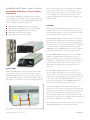
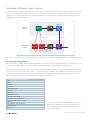
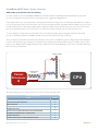
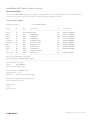
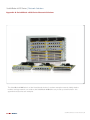
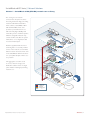
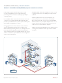
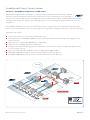
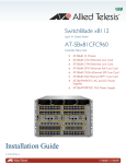
Technical Guide
SwitchBlade x8100 Series System Overview
®
Next Generation Intelligent Layer 3+ Chassis Switches
SwitchBlade x8100 Series | System Overview
Contents
Introduction..................................................................................................................................................................................3
SwitchBlade x8100 Series – Chassis...........................................................................................................................4
SwitchBlade x8100 Series – Chassis...........................................................................................................................5
SwitchBlade x8100 Series – Control and Line Cards...................................................................................6
CFC400 Control Card............................................................................................................................................6
CFC960 Control Card.............................................................................................................................................7
SwitchBlade x8100 Series – Power Supplies and Cooling........................................................................8
System PSUs....................................................................................................................................................................8
PoE PSUs............................................................................................................................................................................8
System cooling................................................................................................................................................................9
SwitchBlade x8100 Series – Internal Architecture..........................................................................................10
Data plane connectivity...........................................................................................................................................10
Data plane load balancing......................................................................................................................................11
Data plane traffic management.........................................................................................................................11
Control plane connectivity...................................................................................................................................12
Control card synchronization.............................................................................................................................13
CPU traffic prioritization and rate limiting................................................................................................14
SwitchBlade x8100 Series – Switch Startup.........................................................................................................15
Switch startup operation.......................................................................................................................................15
Managing the chassis..................................................................................................................................................15
Chassis reboot................................................................................................................................................................15
CFC fast failover .........................................................................................................................................................15
Hot-swapping CFCs...................................................................................................................................................15
Hot-swapping line cards..........................................................................................................................................15
Software upgrading....................................................................................................................................................16
Incompatible software releases.........................................................................................................................16
CFC disabled master ...............................................................................................................................................16
System information.....................................................................................................................................................17
Appendix A: SwitchBlade x8100 Series Network Solutions .......................................19
Solution 1 – SwitchBlade x8100 (CFC400) network core resiliency...................................20
Solution 2 – SwitchBlade x8100 (CFC400) distributed network with EPSRing.........21
Solution 3 – SwitchBlade x8100 (CFC960) complete network core resilience..........22
Solution 4 – SwitchBlade x8100 (CFC960) distributed collapsed backbone................23
Solution 5 – SwitchBlade x8100 Series as AMF master.................................................................24
2 | SwitchBlade x8100 Series System Overview
alliedtelesis.com
SwitchBlade x8100 Series | System Overview
Introduction
The SwitchBlade x8100 Series next generation intelligent Layer 3+ chassis switches are designed to deliver high availability, wire-speed
performance, and a high port count. Allied Telesis advanced features make them the ideal solution for the modern enterprise network
where resiliency, reliability and high performance are the key requirements.
The SwitchBlade x8100 is available in 6-slot and 12-slot models, with an extensive range of connectivity options. Dual control cards are
partnered with the line card slots. Gigabit and 10 Gigabit line card options ensure a system capable of meeting the requirements of
today’s networks, and the flexibility to expand when required.
Two control card options, the CFC400 and CFC960, are available, which allow the SwitchBlade x8100 Series to be deployed in
medium to large scale networks. The CFC960 is a more powerful control card to support larger networks, and can double the
backplane bandwidth of the chassis. It also supports advanced features like VCStack Plus and VRF-Lite. VCStack Plus allows two chassis
to be stacked together into a single virtual unit. This creates a powerful and completely resilient network core, which can even be
distributed over long distance
The SwitchBlade x8100 Series, along with other Allied Telesis SwitchBlade and X Series switches, runs the AlliedWare Plus operating
system, providing an industry standard CLI and a comprehensive feature-set. As an alternative to the CLI, a GUI (Graphical User
Interface) allows for web based monitoring and configuration of the SwitchBlade x8100 Series.*
This document provides an overview of the SwitchBlade x8100 Series hardware, internal architecture and switch operation. Appendix
A highlights two CFC400 based network scenarios and two CFC960 based network scenarios where the SwitchBlade x8100 Series
can provide powerful solutions. A 5th scenario shows how the SwitchBlade x8100 Series can be the center of an Allied Telesis
Management Framework (AMF) network. AMF automates many everyday network administration tasks. The complete network can
be managed as a single virtual device with powerful centralized management features. Growing the network can be accomplished with
plug-and-play simplicity, and network node recovery is fully zero-touch.
*The GUI for a CFC960 based system will be available Q2 2014
SwitchBlade x8100 Series System Overview | 3
SwitchBlade x8100 Series | System Overview
SwitchBlade x8100 Series – Chassis
The SwitchBlade x8112 is a 7 rack unit modular chassis
comprising:
■■ 2 Controller Fabric Card (CFC) slots
■■ 10 Line card slots
■■ 2 System PSU bays
■■ 2 PoE PSU bays
■■ Fan tray
A number of components have specific positions in the chassis:
■■ System PSUs use the 2 right hand bays
■■ PoE PSUs use the 2 left hand bays
■■ CFCs use slots 5 & 6
■■ Line cards use slots 1-4, 7-12
All of the above system components are hot-swappable to maximise system uptime during maintenance or reconfiguration.
PoE PSU bays
System PSU bays
10 x Line card slots
7RU
2 x Control Fabric
card slots
Fan-tray bay
The rear of the chassis provides power cord receptacles for the system and PoE power supplies. The backplane of the SwitchBlade
x8112 is completely passive for high reliability, and is maintenance free. There are 3 extra small covers on the rear of the chassis for
easy access to system components. The left-hand cover provides access to the chassis ID EPROM, and the right-hand covers provide
access to the opto-couplers, used for PSU isolation.
System power
cord receptacles
Chassis ID
EPROM cover
4 | SwitchBlade x8100 Series System Overview
PoE power
cord receptacles
PSU opto-coupler
covers
alliedtelesis.com
SwitchBlade x8100 Series | System Overview
SwitchBlade x8100 Series – Chassis
The SwitchBlade x8106 is a 4 rack unit modular chassis
comprising:
■■ 2 Controller Fabric Card (CFC) slots
■■ 4 Line card slots
»» A 5th Line card can replace one CFC
■■ 2 System PSU bays
■■ 2 PoE PSU bays
■■ Fan tray
A number of components have specific positions in the chassis:
■■ System PSUs use the 2 right hand bays
■■ PoE PSUs use the 2 left hand bays
■■ Line cards use slots 1-4
■■ A CFC uses slots 5
■■ A CFC or Line card uses slots 6
All of the above system components are hot-swappable to maximise system uptime during maintenance or reconfiguration.
PoE PSU bays
System PSU bays
4 x Line card slots
4RU
Fan-tray bay
1 x Control Fabric
card slot
1 x Control Fabric
or Line card slot
The rear of the chassis provides power cord receptacles for the system and PoE power supplies. The backplane of the SwitchBlade
x8106 is completely passive for high reliability, and is maintenance free. There are 3 extra small covers on the rear of the chassis for
easy access to system components. The left-hand cover provides access to the chassis ID EPROM, and the right-hand covers provide
access to the opto-couplers, used for PSU isolation.
System power
cord receptacles
Chassis ID
EPROM cover
PoE power
cord receptacles
PSU opto-coupler
covers
SwitchBlade x8100 Series System Overview | 5
SwitchBlade x8100 Series | System Overview
SwitchBlade x8100 Series – Control and Line Cards
■■ SBx81CFC960 (Controller Fabric Card)
■■ SBx81CFC400 (Controller Fabric Card)
■■ SBx81GT24 (24 x 10/100/1000T Line Card)
■■ SBx81GT40 (40 x 10/100/1000T RJ.5 Line Card)
■■ SBx81GP24 (24 x 10/100/1000T PoE+ Line Card)
■■ SBx81GS24a (24 x 100/1000 SFP Line Card)
■■ SBx81XS6 (6 x 10Gbps (SFP+) Line Card)
Note: The SwitchBlade x8100 Series shares hardware design with
the Layer-2 SwitchBlade x3100 Series chassis. To ensure no possible
conflicts if an incorrect card is installed - if a SwitchBlade x3100 line
card is put into a SwitchBlade x8100 chassis it will not power up,
and is held in reset.
With 10 line card slots available, the SwitchBlade x8112
supports:
■■ 400 GbE copper ports
■■ 240 GbE copper ports with PoE+
■■ 240 GbE fiber ports (SFP)
■■ 60 10GbE ports (SFP+)
■■ or any combination
When using 5 line card slots, the SwitchBlade x8106 supports:
■■ 200 GbE copper ports
■■ 120 GbE copper ports with PoE+
■■ 120 GbE fiber ports (SFP)
■■ 30 10GbE ports (SFP+)
■■ or any combination
CFC400 Control Card
As shown above the CFC400 control card includes a standard
RS-232 asynchronous port, and an Ethernet port for out of
band management. It also includes a USB connector, allowing
the easy transfer of files and additional storage as required (the
USB connector supports USB storage devices only). Centralised
LEDs provide status of all 12 card slots, along with CFC, PSU
and fan tray.
In keeping with our commitment to environmentally friendly
processes and products, the SwitchBlade x8100 Series
is designed to reduce power consumption and minimize
hazardous waste. Features include the use of high efficiency
6 | SwitchBlade x8100 Series System Overview
power supplies and low power chip sets. The CFC400 also
include an ECO-Switch button on the front panel allowing
conservation of additional power by turning off all diagnostic
LED indicators across the chassis when they are
not required.
The name CFC400 is derived from the fact that these control
cards will provide 40 gigabits bandwidth per line card slot (x 10
slots = 400Gbps). With two CFC400 control cards installed,
the system will provide 800Gbps system bandwidth.
alliedtelesis.com
SwitchBlade x8100 Series | System Overview
CFC960 Control Card
The CFC960 shown above provides all of the same connectors
and front panel information as the CFC400 shown previously,
plus 4 x 10GbE SFP+ ports. The SFP+ ports can be used for
standard 10GbE connectivity (fiber only) or for stacking two
SwitchBlade x8100 Series chassis together into a single virtual
unit using VCStack Plus. As the stacking connectors are fiber the
two chassis do not need to be collocated, but can be kilometres
apart – perfect for a distributed core environment, or datamirroring solution (as shown in Appendix A).
The name CFC960 is derived from the fact that these control
cards can provide up to 80Gbps bandwidth per line card slot.
80Gbps x 10 line card slots (SBx8112) 4 SFP+ front panel ports
Inter CFC link
Total
= 800Gbps
= 80Gbps
= 80Gbps
= 960Gbps (CFC960)
Having two CFC960 control cards installed in a SwitchBlade
x8112 provides 1.92Tbps switching fabric.
SwitchBlade x8100 Series System Overview | 7
SwitchBlade x8100 Series | System Overview
SwitchBlade x8100 Series – Power Supplies
and Cooling
The SwitchBlade x8100 Series includes AC and DC system
power supply options. Optional PoE power supplies will supply
power to endpoints when used with the SBx81GP24 line card.
The power supplies and fan tray available are:
■■ SBxPWRSYS1 (1200W AC System Power Supply)
■■ SBxPWRSYS1-80 (1200W DC System Power Supply)
■■ SBxPWRPOE1 (1200W AC PoE Power Supply)
■■ SBxFAN12 (Fan tray for 12 slot chassis)
■■ SBxFAN06 (Fan tray for 6 slot chassis)
The two system and two PoE power supplies have individual
power cord receptacles on the rear of the chassis, so each
can be fed from separate power sources if desired to further
increase reliability and resiliency. For specific power outlet
requirements (dependent on voltage in your country) see the
installation guide.
PoE PSUs
A PoE power supply (SBxPWRPOE1) will fit into the system
PSU bay, but they are electronically keyed so it will not power
up and the chassis won’t boot. Correct PSU placement must be
observed for the system to function correctly.
The SwitchBlade x8100 Series supports PoE+, which supplies
the higher power required from a new generation of network
attached devices. These new devices, such as pan tilt and zoom
IP security cameras, touch screen displays and so on, frequently
require more than the 12.95W available with standard PoE
(IEEE 802.3af). PoE+ (IEEE 802.3at) can provide up to 30W of
power, with a powered device able to draw up to 25.5W.
System PSUs
As with other Allied Telesis advanced switches using modular
power supplies, one PSU is enough to power the complete
SwitchBlade x8100 system. A second power supply will loadshare and provide redundancy. PSUs and the fan tray are all hotswappable so no downtime is encountered during maintenance.
The SwitchBlade x8100 Series supports one or two 1200W
PoE PSUs, so 2400W maximum. This allows power to be
supplied to 80 devices (at the maximum PoE+ specification
of 30W) or 155 devices (at the maximum PoE specification of
15.4W). For devices like IP phones which require less power
(class 2 PoE of around 7W) then a larger number can be
supported.
The SwitchBlade x8100 will quite likely be connected to a
number of different PoE devices, such as IP phones, security
cameras and so on, with each type of device requiring different
power levels. Power budgeting manages the allocation of power
to the devices connected to SBx81GP24 PoE line cards. This
ensures the most efficient use of the 2400W available, and
support for the maximum number of PoE devices.
As with other AlliedWare Plus switches that support PoE,
priority can be set for specific ports (low, high, and critical). This
ensures that important devices continue to receive power even
if the total power budget is exceeded, with power delivered
first to critical, then high, and then low priority devices. Power
capacity for a port can be set to anything from 4W to 30W, and
PoE can also be disabled for a port if desired.
System and PoE power cord receptacles
8 | SwitchBlade x8100 Series System Overview
More information on PoE and its operation can be found in the
SwitchBlade x8100 Series software reference manual.
alliedtelesis.com
SwitchBlade x8100 Series | System Overview
System cooling
Cooling of the SwitchBlade x8100 Series is:
■■ Front to back for the PSUs via their own internal fans
■■ Side to side for the chassis cards via the SBxFAN12 fan tray (which comprises 4 individual fans) for the SwitchBlade x8112. Similarly
the SBxFAN06 comprises 2 individual fans for the SwitchBlade x8106, to draw air through the chassis
The PSU and control/line card sections of the chassis are physically separated to avoid swirling airflow in the multi-direction system.
PSU front-to-back airflow
PSU and System airflow
are physically separated
System left-to-right
side airflow
Fan-tray bay
Any control/line card slot that is unoccupied should have a blanking plate installed to assist airflow through the system and ensure
adequate cooling.
SwitchBlade x8100 Series System Overview | 9
SwitchBlade x8100 Series | System Overview
SwitchBlade x8100 Series – Internal
Architecture
Data plane connectivity
To avoid any single point of failure, the data plane employs a
dual star topology. Two 10Gbps data lanes, one from each
packet processor on the SBx81CFC400 control card, connect to
each line card slot. This provides each line card slot with 20Gbps
full duplex per control card, or 40Gbps full duplex per line card
slot when two CFCs are installed (x2 = 80Gbps bandwidth per
line card slot in both directions), as shown below:
The backplane of the SwitchBlade x8100 Series chassis is
completely passive, providing high reliability. There are two main
interfaces between the control and line cards – the data plane
and the control plane.
The data plane switching fabric is comprised of packet
processors on the control and line cards, which are
interconnected via the backplane for data traffic through the
chassis. The control plane uses switch chips on the CFC and line
cards which are separate from the data plane switching fabric,
and is used for internal chassis related communication such as
switch management, transferring software releases and so on.
The SBx81CFC960 control cards provide the same backplane
bandwidth with current line cards. When partnered with the
new SBx81XS16 line card (due Q2 2014), the SBx81CFC960 will
be able to provide double the backplane bandwidth.
Linecard
Slot 1
Linecard
Slot 2
Linecard
Slot 3
Linecard
Slot 4
Linecard
Slot 7
Packet
Processor
Packet
Processor
Packet
Processor
Packet
Processor
Packet
Processor
10Gbps Links
Control Card
Slot 5
Packet
Processor
A
Packet
Processor
B
Packet
Processor
A
Packet
Processor
B
Control Card
Slot 6
4 x 10Gbps Links = 40Gbps Full Duplex
x 2 = 80Gbps/Linecard Slot
Packet
Processor
Packet
Processor
Packet
Processor
Packet
Processor
Packet
Processor
Linecard
Slot 8
Linecard
Slot 9
Linecard
Slot 10
Linecard
Slot 11
Linecard
Slot 12
This diagram shows the data plane connectivity for the SwitchBlade x8112 12 slot chasis. The SwitchBlade x8106 6 slot chassis has
the same connectivity, but to only 4 line card slots, or can be used with a single control card and 5 line cards with half the backplane
bandwidth.
10 | SwitchBlade x8100 Series System Overview
alliedtelesis.com
SwitchBlade x8100 Series | System Overview
A SwitchBlade x8100 Series with two CFC400s or two CFC960s installed provides 80Gbps bandwidth per line card slot*. This
provides current line cards with the following performance characteristics:
■■ SBx81GT24 (24 x 10/100/1000T Line Card)
non-blocking
non-blocking
■■ SBx81GP24 (24 x 10/100/1000T PoE+ Line Card)
non-blocking
■■ SBx81GS24a (24 x 100/1000 SFP Line Card)non-blocking
■■ SBx81XS6 (6 x 10Gbps (SFP+) Line Card)3:2 blocking
■■ SBx81GT40 (40 10/100/1000T RJ.5 Line Card)
Data plane load balancing
To load balance the traffic across the SwitchBlade x8100 Series backplane, a hashing algorithm is used, so that traffic entering the
line card from different individual hosts will utilise different data lanes across the backplane. There will either be two or four data
lanes available between the line card and control cards, depending on whether one or two control cards are installed in the chassis.
These data lanes are treated as a single virtual port (link aggregation group) and so data is hashed down one of the members of
the aggregation group. By default this is dependent on the source and destination MAC addresses, and source and destination IP
addresses. This spreads the data traffic across the backplane and provides a high performance load-balanced system.
Data plane traffic management
The SwitchBlade x8100 Series chassis uses a distributed switching architecture, with packet processors on each individual line card.
Traffic on the data plane is managed by a combination of synchronized hardware tables, and the fact that the system uses an internal
network for forwarding packets as appropriate between the packet processors.
Hardware tables are synchronized on all installed CFC and line cards, so the same forwarding/routing information is available locally for
lookup on ingress of external traffic. Packets that are destined to egress on a different line card are forwarded across the backplane
and on to the appropriate card.
*The SBx81CFC960 will be able to provide double the backplane bandwidth when partnered with the SBx81XS16 line card (due Q2 2014)
SwitchBlade x8100 Series System Overview | 11
SwitchBlade x8100 Series | System Overview
Control plane connectivity
The SwitchBlade x8100 Series control plane is facilitated by gigabit switch chips fitted to both the CFC and line cards. These provide a
gigabit connection between the CFCs, and from each CFC to each of the line card slots, as shown below:
Linecard
Slot 1
Linecard
Slot 2
Linecard
Slot 3
Linecard
Slot 4
Linecard
Slot 7
Packet
Processor
Packet
Processor
Packet
Processor
Packet
Processor
Packet
Processor
Control
Plane
Switch
Chip
Control
Plane
Switch
Chip
Control
Plane
Switch
Chip
Control
Plane
Switch
Chip
Control
Plane
Switch
Chip
1 Gbps Links
Control Packet
Card Processor
A
Slot 5
Packet
Processor
B
Control
Plane
Switch
Chip
Control
Plane
Switch
Chip
Packet
Processor
A
Control
Packet
Card
Processor
B
Slot 6
Control
Plane
Switch
Chip
Control
Plane
Switch
Chip
Control
Plane
Switch
Chip
Control
Plane
Switch
Chip
Control
Plane
Switch
Chip
Packet
Processor
Packet
Processor
Packet
Processor
Packet
Processor
Packet
Processor
Linecard
Slot 8
Linecard
Slot 9
Linecard
Slot 10
Linecard
Slot 11
Linecard
Slot 12
This diagram shows the control plane connectivity for the SwitchBlade x8112 12 slot chassis. The SwotchBlade x8106 6 slot chassis has
the same connectivity, but to only 4 line card slots.
12 | SwitchBlade x8100 Series System Overview
alliedtelesis.com
SwitchBlade x8100 Series | System Overview
Control plane data is managed by the CPU, as it consists of chassis related communication such as switch management, file transfer
and so on. To facilitate this, the CPU is connected to the control plane switch chip with a 1Gbps link. It is also connected to each
packet processor via 2Gbps PCI Express to manage data traffic that needs to be processed by the switch, for example protocol
management packets (STP, EPSR etc).
1 Gbps links
Line Card
Slot 1
Packet
Processor
CPU
2 Gbps
1 Gbps link
10 Gbps link
Control Card
Slot 5
Packet
Processor
A
Packet
Processor
B
CPU
2 Gbps
Control
Plane
Switch
Chip
Control
Plane
Switch
Chip
1 Gbps links
There is, of course, interconnection with other aspects of the cards not shown, such as SDRAM, Flash memory, USB slot, PHYs etc.
Control card synchronization
When two CFCs are installed in the SwitchBlade x8100, they provide an active/active switching architecture. The packet processors
on both CFCs are fully utilised to double the available backplane bandwidth from 40 to 80Gbps per line-card slot.
One of the CFCs will become the active chassis master. In normal operation this will be the CFC on the left-hand side (slot 5). The
active chassis master manages the system, and processes CPU bound network traffic. The standby CFC runs all network protocol
modules and is kept in sync with the active CFC, so is available in ‘hot-standby’ for near hitless failover if required. The network
information tables that are synchronized between the two CFCs are shown below.
Tables synchronized between the two CFCs
FDB
ARP Table
IP route DB
RIP route DB
OSPF Neighbor/Route DB
VRRP Status
IGMP Snooping
IGMP Multicast group table
PIM-SM/DM multicast route DB
LOCAL RADIUS authentication information
DHCP Server IP address assignment information
EPSR status
802.1x/MAC/WEB authentication information
IPv6 Neighbor table
RiPng route DB
Note: The first three tables listed (FDB, ARP Table and IP route
DB) are also synchronized between the CFC and line cards, so
forwarding/routing information is available locally for lookup on
ingress of external traffic.
SwitchBlade x8100 Series System Overview | 13
SwitchBlade x8100 Series | System Overview
CPU traffic prioritization and rate limiting
In a Layer 3 switch, such as the SwitchBlade x8100 Series, data traffic will be predominantly switched in hardware by the packet
processors, keeping wire-speed performance for the large number of gigabit and 10 gigabit ports.
Control plane traffic is processed by the CPU, as it manages internal switch management. Some data plane traffic will also be required
to be processed by the CPU on the master CFC, such as protocol management traffic (e.g. EPSR, LACP, STP, OSPF etc) and responses
to traffic destined for the switch itself (e.g. ARP replies etc). Any time traffic is trapped to the CPU it goes to the CPU on the master
CFC via a nominated packet processor (i.e. the first one on the master CFC) even if the trap was done by the line card.
To ensure timely processing of packets by the CPU on the master CFC, data plane traffic arriving at the CPU from the packet
processor is prioritized and there is a 30Mbps rate limit set to protect the CPU from being overloaded.
There are 8 queues that CPU bound traffic can be placed into. These queues are utilized to guarantee high priority packets that affect
network control and topology are always processed before lower priority traffic when the CPU is busy. For example, Layer-2 control
packets such as ESPR are placed in high priority queues by default. This ensures they will always receive service, even if the CPU is busy
with other lower priority traffic.
Priority queues
7
5
4
3
2
Traffic bound
for CPU
Packet
Processor
B
1
0
CPU
2 Gbps
The CPU priority queues used by the various protocols are shown in the table below.
CPU Ingress priority queues
Protocol
CPU Queue
7
L2 Control Packets/EPSR/Loop Detect
6
DHCP Snooped Pkts
5
4
UC IPV6 Interface route
Link-local multicast protocols (OSPF/RIPv2/RIPng/PIM/VRRP/IGMP)
Default/ARP Reply/ARP Request/L2 unregistered MC
3
UC IPV4 Interface route
1
UC IPV4-6 Default route/L3 unregistered MC/sFlow Samples
0
14 | SwitchBlade x8100 Series System Overview
2
alliedtelesis.com
SwitchBlade x8100 Series | System Overview
SwitchBlade x8100 Series – Switch Startup
One of the key differences between the SwitchBlade x8100
Series and other switches running the AlliedWare Plus
operating system is that the SwitchBlade x8100 Series has
multiple CPUs (one on each card). While the CPU on the
master CFC will run the system, because the other control and
line cards have their own CPU and packet processors, they all
need to have a copy of the release software loaded.
Switch startup operation
The SwitchBlade x8100 Series has extensive monitoring of
hardware to assist in management of the system. Any problem
with a PSU, Fan etc is detected, and appropriate alarms
generated to let the user know.
Chassis reboot
As mentioned above, which CFC becomes the chassis master is
deterministic, with preference given to the left-hand side (slot 5).
This preference is enforced when the chassis is rebooted from
the command line, or is power-cycled.
When the switch starts up, assuming two CFCs are installed,
preference is given to the left-hand side (slot 5) as to which CFC
becomes chassis master. If no CFC is installed in slot 5, then
the right-hand side CFC (slot 6) will become chassis master. To
facilitate this operation, the CFC in the right-hand side delays
asserting mastership, if it detects a CFC in the left-hand side.
This allows the left-hand side CFC to become master. After
waiting for 60 seconds, the right-hand side CFC will assert
mastership, as there is either no CFC in the left-hand slot, or it is
dead or failing to boot.
CFC fast failover
The CFC boots normally, loading its software release from flash
by default. The CFC runs a DHCP and TFTP server for the line
cards to access the software release over the internal network.
Hot-swapping CFCs
The mechanism employed to accomplish this file transfer from
CFC to the line cards is as follows: The CFC saves a copy of
the running release to a “tftpboot” directory, which the TFTP
server uses to serve releases to the line cards. At startup, the
bootloader on the line card periodically broadcasts a BOOTP
request. The DHCP server is listening on the CFC for BOOTP
requests and it responds with the line card’s management
VLAN IP address, and the release file to boot is sent via TFTP.
When the chassis boots up, the chassis mastership is asserted
as soon as possible. This is in order to start up the TFTP server
on the chassis master so that the line card boot up can occur as
quickly as possible, to minimize the total chassis startup time.
In the event that the chassis master is hot-swapped out, the
standby CFC will become active master, taking over all control
functions.
The standby CFC runs all network protocol modules and
is kept in sync with the active CFC, so is available in ‘hotstandby’ for near hitless failover if required. This occurs almost
instantaneously, and testing has shown no noticeable disruption
to a streaming video on a master CFC hot-swap.
The standby CFC can be hot-swapped if required for
maintenance, with no disruption to the system (apart from the
fact that the backplane bandwidth will be temporarily halved).
A newly installed standby CFC will once again double the
backplane bandwidth.
If the master CFC is hot-swapped out, the standby CFC will
assume the role of master almost instantaneously. Now the
right-hand side (and only) CFC is controlling the system. Once a
second CFC is replaced in the left-hand-side slot, it will become
the standby CFC. This new standby CFC will have synchronized
tables with the master and provide double the backplane
bandwidth, but does not take over as master again. If the chassis
were rebooted or power cycled, the left-hand side CFC would
become master again.
Hot-swapping line cards
Managing the chassis
The SwitchBlade x8100 Series provides a standard RS-232
asynchronous port, and an Ethernet port for out-of-band
management of the system. Connecting to either asynchronous
port will provide management of the system via the chassis
master. To connect to the system via Ethernet, the Ethernet
port on the master CFC must be used, as the standby CFC’s
Ethernet port is administratively down.
Line cards can be hot-swapped with no disruption to the
operation of other cards in the system, so traffic continues as
expected across other connections. A newly inserted line card
will utilize the same mechanism described previously to receive
a software release from the master CFC (i.e. a BOOTP request,
with subsequent DHCP internal IP address and TFTP software
release delivery).
SwitchBlade x8100 Series System Overview | 15
SwitchBlade x8100 Series | System Overview
Software upgrading
Like other AlliedWare Plus switches, the SwitchBlade x8100
Series has no restriction on upgrading between software
versions. So minor release upgrades (e.g. 5.4.3-2.5 to 5.4.3-3.6)
and major release upgrades (e.g. 5.4.3-2.5 to 5.4.4) are both
supported.
Upgrading the software on a SwitchBlade x8100 Series requires
the software to be distributed to all cards in the system. For the
user, however this is very straightforward, as it is handled behind
the scenes as described earlier.
To upgrade to a newer software release, it simply needs to be
loaded onto the master CFC, set to be used, and the chassis
rebooted. This will cause the CFC to boot with the new
software release, and distribute it to the other cards via the
internal network using its TFTP server.
Incompatible software releases
It is imperative that all cards in the SwitchBlade x8100 system
are running the same software release. This is managed by
the master CFC distributing the software release to the line
cards. This guarantees that the line cards always have the same
software release on them as the master CFC.
There are some situations where it would be possible to end
up with incompatible software versions between the two CFCs.
These are handled by the SwitchBlade x8100 to ensure that a
system will not be running this way.
If the standby CFC boots with a different software version from
what is installed on the master, it would not be in a position to
take over as master if required, as its software would not match
what is installed on the line cards by the original master CFC.
To avoid this possibility, the chassis will automatically upgrade
the standby CFC to match the software installed on the master.
There are two mechanisms to do this depending on how
different the version of software release is:
16 | SwitchBlade x8100 Series System Overview
1) Minor software release variation:
If the two CFCs have a minor release variation, for example,
5.4.3-2.5 and 5.4.3-3.6, they are still able to communicate. As
such the master CFC will use auto-sync to push the software
release that should be used to the standby CFC, which will then
reboot using the correct software release.
2) Major software release variation:
If the two CFCs have a major release variation, for example,
5.4.3-2.5 and 5.4.4-0.1, then the mechanism used to load
software onto the line cards is employed. A trigger file is written
to flash on the standby CFC and it is rebooted. The bootloader
finds the file and attempts to boot the CFC via a BOOTP
request, with subsequent TFTP delivery of the software release
as happens for the line cards. Auto-sync will sync the file to the
standby CFCs flash, so it is ready for any subsequent reboots
with the correct software release.
CFC disabled master
When incompatible software releases present themselves,
there is a situation where the standby CFC could end up
unusable in the system, and as such enter the “disabled master”
state. In this state the system will run with only the master
CFC, meaning only half the backplane bandwidth that would
otherwise be available. This disabled master is not operational
and as such not available to take over as master in the event
of a master CFC failure or hot-swap, so the situation needs
resolving. Log entries are created when a CFC enters the
disabled master state.
The reason a CFC could enter the disabled master state is
that there is not enough flash memory available to store the
software release that the master CFC wishes to auto-sync.
When auto-sync attempts to sync the correct software release
to the standby CFC, if its flash does not have enough space, old
software releases are deleted to make room. The only reason
for a failure to store the new software release is if the flash is full
of other files (core files and so on). As there is 128MB of flash
on the CFC400 and 512MB on the CFC960, this should be a
very rare occurrence.
alliedtelesis.com
SwitchBlade x8100 Series | System Overview
System information
Once the SwitchBlade x8100 chassis has successfully booted, information about the system is available from the command line. For
example, ‘show system’ and ‘show card’ provide an overview of hardware installed and its status.
awplus# show system
Switch System Status
Fri Mar 30 02:44:10 2012
Board
ID Bay Board Name
Rev Serial number
------------------------------------------------------------------------------------------------------------------------------------------Chassis 315
AT-SwitchBlade x8112
E-0 A042764112500070
Blade 317 Bay1 AT-SBx81GP24
D-0 A042774112800031
Blade 353 Bay2 AT-SBx81XS6
X8-0 A045624113500003
Blade 317 Bay3 AT-SBx81GP24
D-0 A042774112700005
Controller 316 Bay5 AT-SBx81CFC400
F-0 A042854111300027
Controller 316 Bay6 AT-SBx81CFC400
F-0 A042854111300029
Blade 352 Bay7 AT-SBx81GS24a
C-1 A042824112400004
Blade 351 Bay11 AT-SBx81GT24
B-1 A044024110900001
Blade 352 Bay12 AT-SBx81GS24a
C-1 A042824104600004
PSU
319 PSUA AT-SBxPWR-SYS/AC
A-0 Fan module 321 FAN1
T-SBxFAN12
E-0 A042844112400016
------------------------------------------------------------------------------------------------------------------------------------------RAM: Total: 513436 kB Free: 365932 kB
Flash: 126.0MB Used: 121.2MB Available: 4.8MB
------------------------------------------------------------------------------------------------------------------------------------------Environment Status : Normal
Uptime
: 0 days 00:03:26
Bootloader version : 2.0.7-devel
Current software : SBx8100-5.4.2.rel
Software version : 5.4.2
Build date
: Fri Mar 30 14:53:19 NZDT 2012
Current boot config: flash:/default.cfg (file exists)
User Configured Territory: usa
System Name
awplus
System Contact
SwitchBlade x8100 Series System Overview | 17
SwitchBlade x8100 Series | System Overview
System Location
awplus# show card
Slot Card Type
State
------------------------------------------------------------------------------------------------------------------------------------------1 AT-SBx81GP24 Online
2 AT-SBx81XS6 Online
3 AT-SBx81GP24 Online
4 5 AT-SBx81CFC400 Online (Active)
6 AT-SBx81CFC400 Online (Standby)
7 AT-SBx81GS24a Online
8 9 10 11 AT-SBx81GT24 Online
12 AT-SBx81GS24a Online
-------------------------------------------------------------------------------------------------------------------------------------------
18 | SwitchBlade x8100 Series System Overview
alliedtelesis.com
SwitchBlade x8100 Series | Network Solutions
Appendix A: SwitchBlade x8100 Series Network Solutions
The SwitchBlade x8100 Series is an ideal chassis based solution for modern enterprise networks. Ideally suited to
medium and large network core solutions, the SwitchBlade x8100 Series can provide a powerful solution - this
appendix showcases five such examples.
SwitchBlade x8100 Series Network Solutions | 19
SwitchBlade x8100 Series | Network Solutions
Solution 1 – SwitchBlade x8100 (CFC400) network core resiliency
10
x2
The convergence of network
services in the enterprise has led to
increasing demand for high performing
networks with minimal downtime.
In this solution, a SwitchBlade x8112
with dual CFC400 control cards
provides a powerful network core
with extremely high reliability. PSU
redundancy ensures maximum uptime,
while hot-swappable PSUs, fan tray,
control and line cards allow for system
maintenance or reconfiguration with
no network interruption.
10
x2
4
10 0-2
x5 x60
10
x2
4
10 0-2
x5 x60
Link aggregation across line cards
to servers, network storage, and
distribution switches leaves no single
point of failure in this high performing
network core.
10
x2
Real-time applications like VoIP and
streaming video are assured premium
service on the network, as near hitless
failover between the dual control cards
on the SwitchBlade x8112 means there
is no perceptible disruption in the case
of a problem.
Network Attached
Storage
2
11
x8
SB
Server
Farm
10
x2
er
ut
Ro
10 Gigabit link
1 Gigabit link
10/100 link
Link aggregation
20 | SwitchBlade x8100 Series Network Solutions
Internet
alliedtelesis.com
SwitchBlade x8100 Series | Network Solutions
Solution 2 – SwitchBlade x8100 (CFC400) distributed network with EPSRing
Wherever a distributed network design is required,
Allied Telesis Ethernet Protection Switched Ring (EPSRing) with
the SwitchBlade x8106 is ideal, providing high-speed 10GbE
connectivity. Failover in a little as 50ms prevents a node or
link failure from affecting customer experience, even when
using demanding applications such as IP telephony and video
monitoring.
This is the ideal solution for ensuring continual access to online
resources and applications in a multi-building business. Now
that technology has made high-availability and high-bandwidth
so accessible, corporate business, education providers and
other enterprise network users can enjoy the many benefits
that EPSRing provides. This advanced self-healing network
technology meets today’s constant demand for information.
10
x6
10
x6
10
x6
6
6
10
x8
SB
810
SBx
10
x5
x8
SB
6
10
Servers
10 Gigabit link
1 Gigabit link
10/100 link
Link aggregation
SwitchBlade x8100 Series Network Solutions | 21
SwitchBlade x8100 Series | Network Solutions
Solution 3 – SwitchBlade x8100 (CFC960) complete network core resilience
Today’s large enterprises demand ready access to online
resources and applications. These needs require a high
performing network, one that can seamlessly carry multiple
converged services.
SwitchBlade x8106 chassis with CFC400 control cards are used
to aggragate tracffic from other buildings, increasing network
resilience.
Two SwitchBlade x8112 chassis with dual CFC960 control cards
combine to form a single virtual unit with VCStack Plus. This
provides a powerful network core, with complete resiliency, and
the simplicity of managing just one device.
Link aggregation across the two chassis to servers, network
storage, and distribution switches leaves no single point of
failure in this high performing network core, ensuring device and
path resiliency. Each individual chassis has PSU redundancy to
ensure maximum uptime. Hot-swappable PSUs, fan tray, control
and line cards allow for system maintenance and reconfiguration
with no network interruption.
Real-time applications like VoIP and streaming video are
assured premium service on the network, as near hitless
failover between the dual control cards on each SwitchBlade
x8112 means there is no perceptible disruption in the case of a
problem. Even if a whole chassis is powered down, access to
online resources is retained without disruption.
With the benefits of high availability, increased capacity and ease
of management, VCStack Plus makes large networks reliable
and simple.
10
x2
10
x2
4
10 0-2
x5 x60
10
x2
10
x2
4
10 0-2
x5 x60
0
x21
10
x2
Server
Rack
10
x2
2
11
x8
SB
6
810
SBx
Network
Attached
Storage
2
11
x8
SB
0
x21
6
10
x8
SB
er
ut
Ro
er
ut
Ro
Dedicated WAN
to remote office
Internet
10 Gigabit link
1 Gigabit link
Link aggregation
22 | SwitchBlade x8100 Series Network Solutions
alliedtelesis.com
SwitchBlade x8100 Series | Network Solutions
Solution 4 – SwitchBlade x8100 (CFC960) distributed collapsed backbone
As large businesses spread across multiple buildings, both onsite
and across distances, their need for reliable access to online
resources and applications grows. Employees expect seamless
connectivity to data center services from all business locations.
Allied Telesis VCStack Plus allows two SwitchBlade x8100
chassis with dual CFC960 control cards to combine as a single
virtual unit. Fiber stacking connectivity means that the two
chassis do not have to be collocated, but can be kilometres
apart. This provides the complete resiliency of a distributed
backbone with separate physical units. It also retains the
simplicity of a collapsed backbone network, with only a single
virtual core chassis to manage.
With a chassis in two different locations, data center services
can be mirrored for ‘always-on’ access, and to ensure
automated disaster recovery. Each individual chassis has power
and control resiliency to maximize uptime. Management of the
network core remains simple, as the virtual unit formed by the
two SBx8100 chassis keeps all switching and routing information
completely synchronized, for zero-touch failover.
Long-distance VCStack Plus on the SwitchBlade x8100
with CFC960 control cards makes the distributed collapsed
backbone a reality.
Allied Telesis build networks that guarantee data availability for
the large enterprise business.
The distributed collapsed backbone encompasses the best of
both worlds.
10
x2
4
10 0-2
x5 x60
0
x5110
x5
0
x21
10
x2
0
x21
10
x2
4
10 0-2
x5 x60
0
x5110
x5
0
x21
10
x2
0
x21
Network Attached
Storage
Corporate
Data Center
mirror
SBx
2
811
Corporate
Data Center
2
11
x8
SB
Network Attached
Storage
Server
Rack
er
ut
Ro
Server
Rack
VCStack
10 Gigabit link
1 Gigabit link
Link aggregation
Internet
SwitchBlade x8100 Series Network Solutions | 23
SwitchBlade x8100 Series | Network Solutions
Solution 5 – SwitchBlade x8100 Series as AMF master
Allied Telesis Management Framework (AMF) is a sophisticated suite of management tools that provide a simplified
approach to network management. Common tasks are automated or made so simple that the every-day running of
a network can be achieved without the need for highly-trained, and expensive network engineers. Powerful features like centralized
management, auto-backup, auto-upgrade, auto provisioning and auto-recovery enable plug-and-play networking and zero-touch
management.
The SwitchBlade x8100 Series can operate as the AMF network master, storing firmware and configuration backups for all other
network nodes. The AMF master enables auto-provisioning and auto-upgrade by providing appropriate files to new network members.
Key benefits of the solution:
■■ AMF provides automation of many network administration tasks
■■ As the AMF master, the SwitchBlade x8100 stores network back-ups and allows auto-provisioning and auto-upgrade to new
■■
■■
■■
■■
■■
■■
network members
High network core resiliency with SBx8100 dual controller chassis
High network core reliability with dual load-sharing PSUs
No single point of failure with link-aggregation from different line-cards on the core chassis to the distribution switches, and to
servers and network storage
High network bandwidth with distribution switches providing multiple 10gigabit uplinks
SwitchBlade x8100 with CFC400 can operate as master for AMF networks up to 80 nodes
SwitchBlade x8100 with CFC960 can operate as master for AMF networks up to 120 nodes
Internet
er
ut
Ro
Master
0
10
x8
SB
Members
Servers
10
x6
Network
Attached
Storage
Members
0
10
x6
1
x5
CORE
10
x5
10
x5
DISTRIBUTION
10
x5
EDGE
24 | SwitchBlade x8100 Series Network Solutions
alliedtelesis.com
SwitchBlade x8112 | Network Solutions
About Allied Telesis, Inc.
Founded in Japan in 1987 and with offices worldwide, Allied Telesis is a leading provider of networking infrastructure and flexible,
interoperable network solutions.
The company provides reliable video, voice and data network solutions to clients in multiple markets including government, healthcare,
defense, education, retail, hospitality and network service providers.
Allied Telesis is committed to innovating the way in which services and applications are delivered and managed, resulting in increased
value and lower operating costs.
Visit us online at alliedtelesis.com
North America Headquarters | 19800 North Creek Parkway | Suite 100 | Bothell | WA 98011 | USA | T: +1 800 424 4284 | F: +1 425 481 3895
Asia-Pacific Headquarters | 11 Tai Seng Link | Singapore | 534182 | T: +65 6383 3832 | F: +65 6383 3830
EMEA & CSA Operations | Incheonweg 7 | 1437 EK Rozenburg | The Netherlands | T: +31 20 7950020 | F: +31 20 7950021
alliedtelesis.com
© 2014 Allied Telesis Inc. All rights reserved. Information in this document is subject to change without notice. All company names, logos, and product designs that are trademarks or registered trademarks are the property of their respective owners.
C613-05043-00 REV A