1
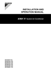
INSTALLATION AND OPERATION MANUAL VRV IV System Air Conditioner System Air Conditioner RYYQ8T7Y1B RYYQ10T7Y1B RYYQ12T7Y1B RYYQ14T7Y1B RYYQ16T7Y1B RYYQ18T7Y1B RYYQ20T7Y1B RYMQ8T7Y1B RYMQ10T7Y1B RYMQ12T7Y1B RYMQ14T7Y1B RYMQ16T7Y1B RYMQ18T7Y1B RYMQ20T7Y1B RXYQ8T7Y1B RXYQ10T7Y1B RXYQ12T7Y1B RXYQ14T7Y1B RXYQ16T7Y1B RXYQ18T7Y1B RXYQ20T7Y1B 1 2 18 10 M M1F R4T 7 R6T R5T 5 R5T 22 7 R6T 16 (S1NPL) (S1NPH) 16 (S1NPH) M1C 13 R21T 6 INV R8T 10-12HP 18 11 13 INV M1C sv 2 3 13 1 12 19 20 1 sv 12 11 HPS (S1PH) 11 3 4 6 14 11 13 11 3 17 4 17 5 4 4 5 16 16 15 15 9 22 9 8 8 22 7 7 19 19 20 20 12 3 18 12 1 4 18 2 1 sv 11 sv 1 sv 6 3 R3T HPS (S1PH) R21T 6 5 15 R3T 18 19 20 M M2F R7T 22 15 (S1NPL) 4 5 9 8 3 M M1F R4T 10 R1T 4 18 R7T 9 8 R1T 4 14 HPS (S2PH) R22T 2 INV R8T 10-12HP M2C 5 6 4 18 10 R6T R5T R7T 3 8 7 R6T (S1NPH) (S1NPL) (S1NPH) R3T 11 sv 6 1 12 R8T INV 10-12HP M1C sv 21 13 11 HPS (S1PH) R21T R21T 18 6 19 1 12 13 21 5 6 7 6 13 11 3 8 6 14 11 13 11 3 17 4 17 4 4 5 5 16 16 15 15 8 8 7 7 19 19 20 21 20 21 12 7 18 12 1 8 18 2 14 HPS (S2PH) R22T 2 INV R8T 10-12HP M2C INV M1C sv 20 11 sv HPS (S1PH) 19 20 3 15 R3T 18 4 M 5 M2F R7T 16 15 (S1NPL) (Y1E) 8 16 M 5 M1F R4T sv R5T 10 R1T 4 18 M 5 M1F R4T 7 R1T 1 CE - DECLARACION-DE-CONFORMIDAD CE - DICHIARAZIONE-DI-CONFORMITA CE - ∆HΛΩΣΗ ΣΥΜΜΟΡΦΩΣΗΣ CE - ERKLÆRING OM-SAMSVAR CE - ILMOITUS-YHDENMUKAISUUDESTA CE - PROHLÁŠENÍ-O-SHODĚ 01 *** Daikin Europe N.V. is authorised to compile the Technical Construction File. 02 *** Daikin Europe N.V. hat die Berechtigung die Technische Konstruktionsakte zusammenzustellen. 03 *** Daikin Europe N.V. est autorisé à compiler le Dossier de Construction Technique. 04 *** Daikin Europe N.V. is bevoegd om het Technisch Constructiedossier samen te stellen. 05 *** Daikin Europe N.V. está autorizado a compilar el Archivo de Construcción Técnica. 06 *** Daikin Europe N.V. è autorizzata a redigere il File Tecnico di Costruzione. 11 * enligt <A> och godkänts av <B> enligt Certifikatet <C>. ** i enlighet med den Tekniska Konstruktionsfilen <D> som positivt intygats av <E> (Fastsatt modul <F>). <G>. Riskkategori <H>. Se även nästa sida. 12 * som det fremkommer i <A> og gjennom positiv bedømmelse av <B> ifølge Sertifikat <C>. ** som det fremkommer i den Tekniske Konstruksjonsfilen <D> og gjennom positiv bedømmelse av <E> (Anvendt modul <F>). <G>. Risikokategori <H>. Se også neste side. 13 * jotka on esitetty asiakirjassa <A> ja jotka <B> on hyväksynyt Sertifikaatin <C> mukaisesti. ** jotka on esitetty Teknisessä Asiakirjassa <D> ja jotka <E> on hyväksynyt (Sovellettu moduli <F>). <G>. Vaaraluokka <H>. Katso myös seuraava sivu. 14 * jak bylo uvedeno v <A> a pozitivně zjištěno <B> v souladu s osvědčením <C>. ** jak bylo uvedeno v souboru technické konstrukce <D> a pozitivně zjištěno <E> (použitý modul <F>). <G>. Kategorie rizik <H>. Viz také následující strana. 15 * kako je izloženo u <A> i pozitivno ocijenjeno od strane <B> prema Certifikatu <C>. ** kako je izloženo u Datoteci o tehničkoj konstrukciji <D> i pozitivno ocijenjeno od strane <E> (Primijenjen modul <F>). <G>. Kategorija opasnosti <H>. Također pogledajte na slijedećoj stranici. Daikin.TCFP.001 AIB Vinçotte (NB0026) D1 — II <D> <E> <F> <G> <H> TÜV (NB1856) 12080901.T30 <C> DAIKIN.TCF.030/09-2012 <B> <A> 19 Direktive z vsemi spremembami. 20 Direktiivid koos muudatustega. 21 Директиви, с техните изменения. 22 Direktyvose su papildymais. 23 Direktīvās un to papildinājumos. 24 Smernice, v platnom znení. 25 Deǧiştirilmiş halleriyle Yönetmelikler. 21 съответстват на следните стандарти или други нормативни документи, при условие, че се използват съгласно нашите инструкции: 22 atitinka žemiau nurodytus standartus ir (arba) kitus norminius dokumentus su sąlyga, kad yra naudojami pagal mūsų nurodymus: 23 tad, ja lietoti atbilstoši ražotāja norādījumiem, atbilst sekojošiem standartiem un citiem normatīviem dokumentiem: 24 sú v zhode s nasledovnou(ými) normou(ami) alebo iným(i) normatívnym(i) dokumentom(ami), za predpokladu, že sa používajú v súlade s našim návodom: 25 ürünün, talimatlarımıza göre kullanılması koşuluyla aşağıdaki standartlar ve norm belirten belgelerle uyumludur: 19 *** Daikin Europe N.V. je pooblaščen za sestavo datoteke s tehnično mapo. 20 *** Daikin Europe N.V. on volitatud koostama tehnilist dokumentatsiooni. 21 *** Daikin Europe N.V. е оторизирана да състави Акта за техническа конструкция. 22 *** Daikin Europe N.V. yra įgaliota sudaryti šį techninės konstrukcijos failą. 23 *** Daikin Europe N.V. ir autorizēts sastādīt tehnisko dokumentāciju. 24 *** Spoločnosť Daikin Europe N.V. je oprávnená vytvoriť súbor technickej konštrukcie. 25 *** Daikin Europe N.V. Teknik Yapı Dosyasını derlemeye yetkilidir. 21 * както е изложено в <A> и оценено положително от <B> съгласно Сертификата <C>. ** както е заложено в Акта за техническа конструкция <D> и оценено положително от <E> (Приложен модул <F>). <G>. Категория риск <H>. Вижте също на следващата страница. 22 * kaip nustatyta <A> ir kaip teigiamai nuspręsta <B> pagal Sertifikatą <C>. ** kaip nurodyta Techninėje konstrukcijos byloje <D> ir patvirtinta <E> (taikomas modulis <F>). <G>. Rizikos kategorija <H>. Taip pat žiūrėkite ir kitą puslapį. 23 * kā norādīts <A> un atbilstoši <B> pozitīvajam vērtējumam saskaņā ar sertifikātu <C>. ** kā noteikts tehniskajā dokumentācijā <D>, atbilstoši <E> pozitīvajam lēmumam (piekritīgā sadaĮa: <F>). <G>. Riska kategorija <H>. Skat. arī nākošo lappusi. 24 * ako bolo uvedené v <A> a pozitívne zistené <B> v súlade s osvedčením <C>. ** ako je to stanovené v Súbore technickej konštrukcie <D> a kladne posúdené <E> (Aplikovaný modul <F>). <G>. Kategória nebezpečia <H>. Viď tiež nasledovnú stranu. 25 * <A>’da belirtildiği gibi ve <C> Sertifikasına göre <B> tarafından olumlu olarak değerlendirildiği gibi. ** <D> Teknik Yapı Dosyasında belirtildiği gibi ve <E> tarafından olumlu olarak (Uygulanan modül <F>) değerlendirilmiştir. <G>. Risk kategorisi <H>. Ayrıca bir sonraki sayfaya bakın. 13 *** Daikin Europe N.V. on valtuutettu laatimaan Teknisen asiakirjan. 14 *** Společnost Daikin Europe N.V. má oprávnění ke kompilaci souboru technické konstrukce. 15 *** Daikin Europe N.V. je ovlašten za izradu Datoteke o tehničkoj konstrukciji. 16 *** A Daikin Europe N.V. jogosult a műszaki konstrukciós dokumentáció összeállítására. 17 *** Daikin Europe N.V. ma upoważnienie do zbierania i opracowywania dokumentacji konstrukcyjnej. 18 *** Daikin Europe N.V. este autorizat să compileze Dosarul tehnic de construcţie. 16 * a(z) <A> alapján, a(z) <B> igazolta a megfelelést, a(z) <C> tanúsítvány szerint. ** a(z) <D> műszaki konstrukciós dokumentáció alapján, a(z) <E> igazolta a megfelelést (alkalmazott modul: <F>). <G>. Veszélyességi kategória <H>. Lásd még a következő oldalon. 17 * zgodnie z dokumentacją <A>, pozytywną opinią <B> i Świadectwem <C>. ** zgodnie z archiwalną dokumentacją konstrukcyjną <D> i pozytywną opinią <E> (Zastosowany moduł <F>). <G>. Kategoria zagrożenia <H>. Patrz także następna strona. 18 * aşa cum este stabilit în <A> şi apreciat pozitiv de <B> în conformitate cu Certificatul <C>. ** conform celor stabilite în Dosarul tehnic de construcţie <D> şi apreciate pozitiv de <E> (Modul aplicat <F>). <G>. Categorie de risc <H>. Consultaţi de asemenea pagina următoare. 19 * kot je določeno v <A> in odobreno s strani <B> v skladu s certifikatom <C>. ** kot je določeno v tehnični mapi <D> in odobreno s strani <E> (Uporabljen modul <F>). <G>. Kategorija tveganja <H>. Glejte tudi na naslednji strani. 20 * nagu on näidatud dokumendis <A> ja heaks kiidetud <B> järgi vastavalt sertifikaadile <C>. ** nagu on näidatud tehnilises dokumentatsioonis <D> ja heaks kiidetud <E> järgi (lisamoodul <F>). <G>. Riskikategooria <H>. Vaadake ka järgmist lehekülge. CE - ATITIKTIES-DEKLARACIJA CE - ATBILSTĪBAS-DEKLARĀCIJA CE - VYHLÁSENIE-ZHODY CE - UYUMLULUK-BİLDİRİSİ 10 Direktiver, med senere ændringer. 11 Direktiv, med företagna ändringar. 12 Direktiver, med foretatte endringer. 13 Direktiivejä, sellaisina kuin ne ovat muutettuina. 14 v platném znění. 15 Smjernice, kako je izmijenjeno. 16 irányelv(ek) és módosításaik rendelkezéseit. 17 z późniejszymi poprawkami. 18 Directivelor, cu amendamentele respective. 17 spełniają wymogi następujących norm i innych dokumentów normalizacyjnych, pod warunkiem że używane są zgodnie z naszymi instrukcjami: 18 sunt în conformitate cu următorul (următoarele) standard(e) sau alt(e) document(e) normativ(e), cu condiţia ca acestea să fie utilizate în conformitate cu instrucţiunile noastre: 19 skladni z naslednjimi standardi in drugimi normativi, pod pogojem, da se uporabljajo v skladu z našimi navodili: 20 on vastavuses järgmis(t)e standardi(te)ga või teiste normatiivsete dokumentidega, kui neid kasutatakse vastavalt meie juhenditele: 01 Directives, as amended. 02 Direktiven, gemäß Änderung. 03 Directives, telles que modifiées. 04 Richtlijnen, zoals geamendeerd. 05 Directivas, según lo enmendado. 06 Direttive, come da modifica. 07 Οδηγιών, όπως έχουν τροποποιηθεί. 08 Directivas, conforme alteração em. 09 Директив со всеми поправками. 13 vastaavat seuraavien standardien ja muiden ohjeellisten dokumenttien vaatimuksia edellyttäen, että niitä käytetään ohjeidemme mukaisesti: 14 za předpokladu, že jsou využívány v souladu s našimi pokyny, odpovídají následujícím normám nebo normativním dokumentům: 15 u skladu sa slijedećim standardom(ima) ili drugim normativnim dokumentom(ima), uz uvjet da se oni koriste u skladu s našim uputama: 16 megfelelnek az alábbi szabvány(ok)nak vagy egyéb irányadó dokumentum(ok)nak, ha azokat előírás szerint használják: Machinery 2006/42/EC *** Electromagnetic Compatibility 2004/108/EC * Pressure Equipment 97/23/EC ** 09 соответствуют следующим стандартам или другим нормативным документам, при условии их использования согласно нашим инструкциям: 10 overholder følgende standard(er) eller andet/andre retningsgivende dokument(er), forudsat at disse anvendes i henhold til vore instrukser: 11 respektive utrustning är utförd i överensstämmelse med och följer följande standard(er) eller andra normgivande dokument, under förutsättning att användning sker i överensstämmelse med våra instruktioner: 12 respektive utstyr er i overensstemmelse med følgende standard(er) eller andre normgivende dokument(er), under forutssetning av at disse brukes i henhold til våre instrukser: 07 *** Η Daikin Europe N.V. είναι εξουσιοδοτημένη να συντάξει τον Τεχνικό φάκελο κατασκευής. 08 *** A Daikin Europe N.V. está autorizada a compilar a documentação técnica de fabrico. 09 *** Компания Daikin Europe N.V. уполномочена составить Комплект технической документации. 10 *** Daikin Europe N.V. er autoriseret til at udarbejde de tekniske konstruktionsdata. 11 *** Daikin Europe N.V. är bemyndigade att sammanställa den tekniska konstruktionsfilen. 12 *** Daikin Europe N.V. har tillatelse til å kompilere den Tekniske konstruksjonsfilen. 06 * delineato nel <A> e giudicato positivamente da <B> secondo il Certificato <C>. ** delineato nel File Tecnico di Costruzione <D> e giudicato positivamente da <E> (Modulo <F> applicato). <G>. Categoria di rischio <H>. Fare riferimento anche alla pagina successiva. 07 * όπως καθορίζεται στο <A> και κρίνεται θετικά από το <B> σύμφωνα με το Πιστοποιητικό <C>. ** όπως προσδιορίζεται στο Αρχείο Τεχνικής Κατασκευής <D> και κρίνεται θετικά από το <E> (Χρησιμοποιούμενη υπομονάδα <F>). <G>. Κατηγορία επικινδυνότητας <H>. Ανατρέξτε επίσης στην επόμενη σελίδα. 08 * tal como estabelecido em <A> e com o parecer positivo de <B> de acordo com o Certificado <C>. ** tal como estabelecido no Ficheiro Técnico de Construção <D> e com o parecer positivo de <E> (Módulo aplicado <F>). <G>. Categoria de risco <H>. Consultar também a página seguinte. 09 * как указано в <A> и в соответствии с положительным решением <B> согласно Свидетельству <C>. ** как указано в Досье технического топкования <D> и в соответствии с положительным решением <E> (Прикладной модуль <F>). <G>. Категория риска <H>. Также смотрите следующую страницу. 10 * som anført i <A> og positivt vurderet af <B> i henhold til Certifikat <C>. ** som anført i den Tekniske Konstruktionsfil <D> og positivt vurderet af <E> (Anvendt modul <F>). <G>. Risikoklasse <H>. Se også næste side. 19 ob upoštevanju določb: 20 vastavalt nõuetele: 21 следвайки клаузите на: 22 laikantis nuostatų, pateikiamų: 23 ievērojot prasības, kas noteiktas: 24 održiavajúc ustanovenia: 25 bunun koşullarına uygun olarak: 05 están en conformidad con la(s) siguiente(s) norma(s) u otro(s) documento(s) normativo(s), siempre que sean utilizados de acuerdo con nuestras instrucciones: 06 sono conformi al(i) seguente(i) standard(s) o altro(i) documento(i) a carattere normativo, a patto che vengano usati in conformità alle nostre istruzioni: 07 είναι σύμφωνα με το(α) ακόλουθο(α) πρότυπο(α) ή άλλο έγγραφο(α) κανονισμών, υπό την προϋπόθεση ότι χρησιμοποιούνται σύμφωνα με τις οδηγίες μας: 08 estão em conformidade com a(s) seguinte(s) norma(s) ou outro(s) documento(s) normativo(s), desde que estes sejam utilizados de acordo com as nossas instruções: 10 under iagttagelse af bestemmelserne i: 11 enligt villkoren i: 12 gitt i henhold til bestemmelsene i: 13 noudattaen määräyksiä: 14 za dodržení ustanovení předpisu: 15 prema odredbama: 16 követi a(z): 17 zgodnie z postanowieniami Dyrektyw: 18 în urma prevederilor: 01 * as set out in <A> and judged positively by <B> according to the Certificate <C>. ** as set out in the Technical Construction File <D> and judged positively by <E> (Applied module <F>). <G>. Risk category <H>. Also refer to next page. 02 * wie in <A> aufgeführt und von <B> positiv beurteilt gemäß Zertifikat <C>. ** wie in der Technischen Konstruktionsakte <D> aufgeführt und von <E> (Angewandtes Modul <F>) positiv ausgezeichnet. <G>. Risikoart <H>. Siehe auch nächste Seite. 03 * tel que défini dans <A> et évalué positivement par <B> conformément au Certificat <C>. ** tel que stipulé dans le Fichier de Construction Technique <D> et jugé positivement par <E> (Module appliqué <F>). <G>. Catégorie de risque <H>. Se reporter également à la page suivante. 04 * zoals vermeld in <A> en positief beoordeeld door <B> overeenkomstig Certificaat <C>. ** zoals vermeld in het Technisch Constructiedossier <D> en in orde bevonden door <E> (Toegepaste module <F>). <G>. Risicocategorie <H>. Zie ook de volgende pagina. 05 * como se establece en <A> y es valorado positivamente por <B> de acuerdo con el Certificado <C>. ** tal como se expone en el Archivo de Construcción Técnica <D> y juzgado positivamento por <E> (Modulo aplicado <F>). <G>. Categoría de riesgo <H>. Consulte también la siguiente página. 01 following the provisions of: 02 gemäß den Vorschriften der: 03 conformément aux stipulations des: 04 overeenkomstig de bepalingen van: 05 siguiendo las disposiciones de: 06 secondo le prescrizioni per: 07 με τήρηση των διατάξεων των: 08 de acordo com o previsto em: 09 в соответствии с положениями: EN60335-2-40, * = , , 1, 2, 3, ..., 9 01 are in conformity with the following standard(s) or other normative document(s), provided that these are used in accordance with our instructions: 02 der/den folgenden Norm(en) oder einem anderen Normdokument oder -dokumenten entspricht/entsprechen, unter der Voraussetzung, daß sie gemäß unseren Anweisungen eingesetzt werden: 03 sont conformes à la/aux norme(s) ou autre(s) document(s) normatif(s), pour autant qu'ils soient utilisés conformément à nos instructions: 04 conform de volgende norm(en) of één of meer andere bindende documenten zijn, op voorwaarde dat ze worden gebruikt overeenkomstig onze instructies: RYYQ8T7Y1B*, RYYQ10T7Y1B*, RYYQ12T7Y1B*, RYYQ14T7Y1B*, RYYQ16T7Y1B*, RYYQ18T7Y1B*, RYYQ20T7Y1B*, RYMQ8T7Y1B*, RYMQ10T7Y1B*, RYMQ12T7Y1B*, RYMQ14T7Y1B*, RYMQ16T7Y1B*, RYMQ18T7Y1B*, RYMQ20T7Y1B*, RXYQ8T7Y1B*, RXYQ10T7Y1B*, RXYQ12T7Y1B*, RXYQ14T7Y1B*, RXYQ16T7Y1B*, RXYQ18T7Y1B*, RXYQ20T7Y1B*, CE - IZJAVA O SKLADNOSTI CE - VASTAVUSDEKLARATSIOON CE - ДЕКЛАРАЦИЯ-ЗА-ϹЪОТВЕТСТВИЕ 17 m deklaruje na własną i wyłączną odpowiedzialność, że modele klimatyzatorów, których dotyczy niniejsza deklaracja: 18 r declară pe proprie răspundere că aparatele de aer condiţionat la care se referă această declaraţie: 19 o z vso odgovornostjo izjavlja, da so modeli klimatskih naprav, na katere se izjava nanaša: 20 x kinnitab oma täielikul vastutusel, et käesoleva deklaratsiooni alla kuuluvad kliimaseadmete mudelid: 21 b декларира на своя отговорност, че моделите климатична инсталация, за които се отнася тази декларация: 22 t visiška savo atsakomybe skelbia, kad oro kondicionavimo prietaisų modeliai, kuriems yra taikoma ši deklaracija: 23 v ar pilnu atbildību apliecina, ka tālāk uzskaitīto modeļu gaisa kondicionētāji, uz kuriem attiecas šī deklarācija: 24 k vyhlasuje na vlastnú zodpovednosť, že tieto klimatizačné modely, na ktoré sa vzťahuje toto vyhlásenie: 25 w tamamen kendi sorumluluǧunda olmak üzere bu bildirinin ilgili olduǧu klima modellerinin aşaǧıdaki gibi olduǧunu beyan eder: CE - IZJAVA-O-USKLAĐENOSTI CE - MEGFELELŐSÉGI-NYILATKOZAT CE - DEKLARACJA-ZGODNOŚCI CE - DECLARAŢIE-DE-CONFORMITATE 09 u заявляет, исключительно под свою ответственность, что модели кондиционеров воздуха, к которым относится настоящее заявление: 10 q erklærer under eneansvar, at klimaanlægmodellerne, som denne deklaration vedrører: 11 s deklarerar i egenskap av huvudansvarig, att luftkonditioneringsmodellerna som berörs av denna deklaration innebär att: 12 n erklærer et fullstendig ansvar for at de luftkondisjoneringsmodeller som berøres av denne deklarasjonen, innebærer at: 13 j ilmoittaa yksinomaan omalla vastuullaan, että tämän ilmoituksen tarkoittamat ilmastointilaitteiden mallit: 14 c prohlašuje ve své plné odpovědnosti, že modely klimatizace, k nimž se toto prohlášení vztahuje: 15 y izjavljuje pod isključivo vlastitom odgovornošću da su modeli klima uređaja na koje se ova izjava odnosi: 16 h teljes felelőssége tudatában kijelenti, hogy a klímaberendezés modellek, melyekre e nyilatkozat vonatkozik: CE - DECLARAÇÃO-DE-CONFORMIDADE CE - ЗАЯВЛЕНИЕ-О-СООТВЕТСТВИИ CE - OVERENSSTEMMELSESERKLÆRING CE - FÖRSÄKRAN-OM-ÖVERENSTÄMMELSE 01 a declares under its sole responsibility that the air conditioning models to which this declaration relates: 02 d erklärt auf seine alleinige Verantwortung daß die Modelle der Klimageräte für die diese Erklärung bestimmt ist: 03 f déclare sous sa seule responsabilité que les appareils d'air conditionné visés par la présente déclaration: 04 l verklaart hierbij op eigen exclusieve verantwoordelijkheid dat de airconditioning units waarop deze verklaring betrekking heeft: 05 e declara baja su única responsabilidad que los modelos de aire acondicionado a los cuales hace referencia la declaración: 06 i dichiara sotto sua responsabilità che i condizionatori modello a cui è riferita questa dichiarazione: 07 g δηλώνει με αποκλειστική της ευθύνη ότι τα μοντέλα των κλιματιστικών συσκευών στα οποία αναφέρεται η παρούσα δήλωση: 08 p declara sob sua exclusiva responsabilidade que os modelos de ar condicionado a que esta declaração se refere: Daikin Europe N.V. CE - DECLARATION-OF-CONFORMITY CE - KONFORMITÄTSERKLÄRUNG CE - DECLARATION-DE-CONFORMITE CE - CONFORMITEITSVERKLARING 2P329110-1 declaración: заявление: 06 • Pressione massima consentita (PS): <K> (bar) • Temperatura minima/massima consentita (TS*): * TSmin: temperatura minima nel lato di bassa pressione: <L> (°C) * TSmax: temperatura satura corrispondente alla pressione massima consentita (PS): <M> (°C) • Refrigerante: <N> • Impostazione del dispositivo di controllo della pressione: <P> (bar) • Numero di serie e anno di produzione: fare riferimento alla targhetta del modello 07 • Mέγιστη επιτρεπόμενη πίεση (PS): <K> (bar) • Ελάχιστη/μέγιστη επιτρεπόμενη θερμοκρασία (TS*): * TSmin: Ελάχιστη θερμοκρασία για την πλευρά χαμηλής πίεσης: <L> (°C) * TSmax: Κορεσμένη θερμοκρασία που αντιστοιχεί με τη μέγιστη επιτρεπόμενη πίεση (PS): <M> (°C) • Ψυκτικό: <N> • Ρύθμιση της διάταξης ασφάλειας πίεσης: <P> (bar) • Αριθμός κατασκευής και έτος κατασκευής: ανατρέξτε στην πινακίδα αναγνώρισης του μοντέλου 08 • Pressão máxima permitida (PS): <K> (bar) • Temperaturas mínima e máxima permitidas (TS*): * TSmin: Temperatura mínima em baixa pressão: <L> (°C) * TSmax: Temperatura de saturação correspondente à pressão máxima permitida (PS): <M> (°C) • Refrigerante: <N> • Regulação do dispositivo de segurança da pressão: <P> (bar) • Número e ano de fabrico: consultar a placa de especificações da unidade 09 • Максимально допустимое давление (PS): <K> (бар) • Минимально/Максимально допустимая температура (TS*): * TSmin: Минимальная температура на стороне низкого давления: <L> (°C) * TSmax: Температура кипения, соответствующая максимально допустимому давлению (PS): <M> (°C) • Хладагент: <N> • Настройка устройства защиты по давлению: <P> (бар) • Заводской номер и год изготовления: смотрите паспортную табличку модели 06 Nome e indirizzo dell’Ente riconosciuto che ha riscontrato la conformità alla Direttiva sulle apparecchiature a pressione: <Q> 07 Όνομα και διεύθυνση του Κοινοποιημένου οργανισμού που απεφάνθη θετικά για τη συμμόρφωση προς την Οδηγία Εξοπλισμών υπό Πίεση: <Q> 08 Nome e morada do organismo notificado, que avaliou favoravelmente a conformidade com a directiva sobre equipamentos pressurizados: <Q> 09 Название и адрес органа технической экспертизы, принявшего положительное решение о соответствии Директиве об оборудовании под давлением: <Q> 01 Name and address of the Notified body that judged positively on compliance with the Pressure Equipment Directive: <Q> 02 Name und Adresse der benannten Stelle, die positiv unter Einhaltung der Druckanlagen-Richtlinie urteilte: <Q> 03 Nom et adresse de l’organisme notifié qui a évalué positivement la conformité à la directive sur l’équipement de pression: <Q> 04 Naam en adres van de aangemelde instantie die positief geoordeeld heeft over de conformiteit met de Richtlijn Drukapparatuur: <Q> 05 Nombre y dirección del Organismo Notificado que juzgó positivamente el cumplimiento con la Directiva en materia de Equipos de Presión: <Q> Jean-Pierre Beuselinck Director Ostend, 3rd of September 2012 10 Navn og adresse på bemyndiget organ, der har foretaget en positiv bedømmelse af, at udstyret lever op til kravene i PED (Direktiv for Trykbærende Udstyr): <Q> 11 Namn och adress för det anmälda organ som godkänt uppfyllandet av tryckutrustningsdirektivet: <Q> 12 Navn på og adresse til det autoriserte organet som positivt bedømte samsvar med direktivet for trykkutstyr (Pressure Equipment Directive): <Q> 13 Sen ilmoitetun elimen nimi ja osoite, joka teki myönteisen päätöksen painelaitedirektiivin noudattamisesta: <Q> 10 • Maks. tilladt tryk (PS): <K> (bar) • Min./maks. tilladte temperatur (TS*): * TSmin: Min. temperatur på lavtrykssiden: <L> (°C) * TSmax: Mættet temperatur svarende til maks. tilladte tryk (PS): <M> (°C) • Kølemiddel: <N> • Indstilling af tryksikringsudstyr: <P> (bar) • Produktionsnummer og fremstillingsår: se modellens fabriksskilt 11 • Maximalt tillåtet tryck (PS): <K> (bar) • Min/max tillåten temperatur (TS*): * TSmin: Minimumtemperatur på lågtryckssidan: <L> (°C) * TSmax: Mättnadstemperatur som motsvarar maximalt tillåtet tryck (PS): <M> (°C) • Köldmedel: <N> • Inställning för trycksäkerhetsenhet: <P> (bar) • Tillverkningsnummer och tillverkningsår: se modellens namnplåt 12 • Maksimalt tillatt trykk (PS): <K> (bar) • Minimalt/maksimalt tillatt temperatur (TS*): * TSmin: Minimumstemperatur på lavtrykkssiden: <L> (°C) * TSmax: Metningstemperatur i samsvar med maksimalt tillatt trykk (PS): <M> (°C) • Kjølemedium: <N> • Innstilling av sikkerhetsanordning for trykk: <P> (bar) • Produksjonsnummer og produksjonsår: se modellens merkeplate 13 • Suurin sallittu paine (PS): <K> (bar) • Pienin/suurin sallittu lämpötila (TS*): * TSmin: Alhaisin matalapainepuolen lämpötila: <L> (°C) * TSmax: Suurinta sallittua painetta (PS) vastaava kyllästyslämpötila: <M> (°C) • Kylmäaine: <N> • Varmuuspainelaitteen asetus: <P> (bar) • Valmistusnumero ja valmistusvuosi: katso mallin nimikilpi 14 • Maximální přípustný tlak (PS): <K> (bar) • Minimální/maximální přípustná teplota (TS*): * TSmin: Minimální teplota na nízkotlaké straně: <L> (°C) * TSmax: Saturovaná teplota odpovídající maximálnímu přípustnému tlaku (PS): <M> (°C) • Chladivo: <N> • Nastavení bezpečnostního tlakového zařízení: <P> (bar) • Výrobní číslo a rok výroby: viz typový štítek modelu 15 y nastavak s prethodne stranice: 16 h folytatás az előző oldalról: 17 m ciąg dalszy z poprzedniej strony: 18 r continuarea paginii anterioare: CE - IZJAVA-O-USKLAĐENOSTI CE - MEGFELELŐSÉGI-NYILATKOZAT CE - DEKLARACJA-ZGODNOŚCI CE - DECLARAŢIE-DE-CONFORMITATE 14 Název a adresa informovaného orgánu, který vydal pozitivní posouzení shody se směrnicí o tlakových zařízeních: <Q> 15 Naziv i adresa prijavljenog tijela koje je donijelo pozitivnu prosudbu o usklađenosti sa Smjernicom za tlačnu opremu: <Q> 16 A nyomástartó berendezésekre vonatkozó irányelvnek való megfelelőséget igazoló bejelentett szervezet neve és címe: <Q> 17 Nazwa i adres Jednostki notyfikowanej, która wydała pozytywną opinię dotyczącą spełnienia wymogów Dyrektywy dot. Urządzeń Ciśnieniowych: <Q> 18 Denumirea şi adresa organismului notificat care a apreciat pozitiv conformarea cu Directiva privind echipamentele sub presiune: <Q> 15 • Najveći dopušten tlak (PS): <K> (bar) • Najniža/najviša dopuštena temperatura (TS*): * TSmin: Najniža temperatura u području niskog tlaka: <L> (°C) * TSmax: Standardna temperatura koja odgovara najvećem dopuštenom tlaku (PS): <M> (°C) • Rashladno sredstvo: <N> • Postavke sigurnosne naprave za tlak: <P> (bar) • Proizvodni broj i godina proizvodnje: pogledajte natpisnu pločicu modela 16 • Legnagyobb megengedhető nyomás (PS): <K> (bar) • Legkisebb/legnagyobb megengedhető hőmérséklet (TS*): * TSmin: Legkisebb megengedhető hőmérséklet a kis nyomású oldalon: <L> (°C) * TSmax: A legnagyobb megengedhető nyomásnak (PS) megfelelő telítettségi hőmérséklet: <M> (°C) • Hűtőközeg: <N> • A túlnyomás-kapcsoló beállítása: <P> (bar) • Gyártási szám és gyártási év: lásd a berendezés adattábláján 17 • Maksymalne dopuszczalne ciśnienie (PS): <K> (bar) • Minimalna/maksymalna dopuszczalna temperatura (TS*): * TSmin: Minimalna temperatura po stronie niskociśnieniowej: <L> (°C) * TSmax: Temperatura nasycenia odpowiadająca maksymalnemu dopuszczalnemu ciśnieniu (PS): <M> (°C) • Czynnik chłodniczy: <N> • Nastawa ciśnieniowego urządzenia bezpieczeństwa: <P> (bar) • Numer fabryczny oraz rok produkcji: patrz tabliczka znamionowa modelu 18 • Presiune maximă admisibilă (PS): <K> (bar) • Temperatură minimă/maximă admisibilă (TS*): * TSmin: Temperatură minimă pe partea de presiune joasă: <L> (°C) * TSmax: Temperatură de saturaţie corespunzând presiunii maxime admisibile (PS): <M> (°C) • Agent frigorific: <N> • Reglarea dispozitivului de siguranţă pentru presiune: <P> (bar) • Numărul de fabricaţie şi anul de fabricaţie: consultaţi placa de identificare a modelului 22 t ankstesnio puslapio tęsinys: 23 v iepriekšējās lappuses turpinājums: 24 k pokračovanie z predchádzajúcej strany: 25 w önceki sayfadan devam: CE - ATITIKTIES-DEKLARACIJA CE - ATBILSTĪBAS-DEKLARĀCIJA CE - VYHLÁSENIE-ZHODY CE - UYUMLULUK-BİLDİRİSİ TSmin TSmax <L> <M> <P> <N> PS <K> 40 bar R410A 63 °C –30 °C 40 bar 24 • Maximálny povolený tlak (PS): <K> (bar) • Minimálna/maximálna povolená teplota (TS*): * TSmin: Minimálna teplota na nízkotlakovej strane: <L> (°C) * TSmax: Nasýtená teplota korešpondujúca s maximálnym povoleným tlakom (PS): <M> (°C) • Chladivo: <N> • Nastavenie tlakového poistného zariadenia: <P> (bar) • Výrobné číslo a rok výroby: nájdete na výrobnom štítku modelu 25 • İzin verilen maksimum basınç (PS): <K> (bar) • İzin verilen minimum/maksimum sıcaklık (TS*): * TSmin: Düşük basınç tarafındaki minimum sıcaklık: <L> (°C) * TSmax: İzin verilen maksimum basınca (PS) karşı gelen doyma sıcaklığı: <M> (°C) • Soğutucu: <N> • Basınç emniyet düzeninin ayarı: <P> (bar) • İmalat numarası ve imalat yılı: modelin ünite plakasına bakın 19 Ime in naslov organa za ugotavljanje skladnosti, ki je pozitivno 24 Názov a adresa certifikačného úradu, ktorý kladne posúdil zhodu ocenil združljivost z Direktivo o tlačni opremi: <Q> so smernicou pre tlakové zariadenia: <Q> 20 Teavitatud organi, mis hindas Surveseadmete Direktiiviga 25 Basınçlı Teçhizat Direktifine uygunluk hususunda olumlu olarak ühilduvust positiivselt, nimi ja aadress: <Q> değerlendirilen Onaylanmış kuruluşun adı ve adresi: <Q> 21 Наименование и адрес на упълномощения орган, който се е произнесъл положително относно съвместимостта с Директивата за оборудване под налягане: <Q> 22 Atsakingos institucijos, kuri davė teigiamą sprendimą pagal <Q> AIB VINÇOTTE INTERNATIONAL N.V. slėginės įrangos direktyvą pavadinimas ir adresas: <Q> Diamant Building, A. Reyerslaan 80 23 Sertifikācijas institūcijas, kura ir devusi pozitīvu slēdzienu par B-1030 Brussels, Belgium atbilstību Spiediena lekārtu Direktīvai, nosaukums un adrese: <Q> 19 • Maksimalni dovoljeni tlak (PS): <K> (bar) • Minimalna/maksimalna dovoljena temperatura (TS*): * TSmin: Minimalna temperatura na nizkotlačni strani: <L> (°C) * TSmax: Nasičena temperatura, ki ustreza maksimalnemu dovoljenemu tlaku (PS): <M> (°C) • Hladivo: <N> • Nastavljanje varnostne naprave za tlak: <P> (bar) • Tovarniška številka in leto proizvodnje: glejte napisno ploščico 20 • Maksimaalne lubatud surve (PS): <K> (bar) • Minimaalne/maksimaalne lubatud temperatuur (TS*): * TSmin: Minimaalne temperatuur madalsurve küljel: <L> (°C) * TSmax: Maksimaalsele lubatud survele (PS) vastav küllastunud temperatuur: <M> (°C) • Jahutusaine: <N> • Surve turvaseadme seadistus: <P> (bar) • Tootmisnumber ja tootmisaasta: vaadake mudeli andmeplaati 21 • Максимално допустимо налягане (PS): <K> (bar) • Минимално/максимално допустима температура (TS*): * TSmin: Минимална температура от страната на ниското налягане: <L> (°C) * TSmax: Температура на насищане, съответстваща на максимално допустимото налягане (PS): <M> (°C) • Охладител: <N> • Настройка на предпазното устройство за налягане: <P> (bar) • Фабричен номер и година на производство: вижте табелката на модела 22 • Maksimalus leistinas slėgis (PS): <K> (bar) • Minimali/maksimali leistina temperatūra (TS*): * TSmin: Minimali temperatūra žemo slėgio pusėje: <L> (°C) * TSmax: Prisotinta temperatūra, atitinkamti maksimalų leistiną slėgį (PS): <M> (°C) • Šaldymo skystis: <N> • Apsauginio slėgio prietaiso nustatymas: <P> (bar) • Gaminio numeris ir pagaminimo metai: žiūrėkite modelio pavadinimo plokštelę 23 • Maksimālais pieļaujamais spiediens (PS): <K> (bar) • Minimālā/maksimālā pieļaujamā temperatūra (TS*): * TSmin: Minimālā temperatūra zemā spiediena pusē: <L> (°C) * TSmax: Piesātinātā temperatūra saskaņā ar maksimālo pieļaujamo spiedienu (PS): <M> (°C) • Dzesinātājs: <N> • Spiediena drošības ierīces iestatīšana: <P> (bar) • Izgatavošanas numurs un izgatavošanas gads: skat. modeļa izgatavotājuzņēmuma plāksnītie 20 Deklaratsiooni alla kuuluvate mudelite disainispetsifikatsioonid: 21 Проектни спецификации на моделите, за които се отнася декларацията: 22 Konstrukcinės specifikacijos modelių, kurie susiję su šia deklaracija: 23 To modeļu dizaina specifikācijas, uz kurām attiecas šī deklarācija: 24 Konštrukčné špecifikácie modelu, ktorého sa týka toto vyhlásenie: 25 Bu bildirinin ilgili olduğu modellerin Tasarım Özellikleri: 19 o nadaljevanje s prejšnje strani: 20 x eelmise lehekülje järg: 21 b продължение от предходната страница: CE - IZJAVA O SKLADNOSTI CE - VASTAVUSDEKLARATSIOON CE - ДЕКЛАРАЦИЯ-ЗА-ϹЪОТВЕТСТВИЕ 13 Tätä ilmoitusta koskevien mallien rakennemäärittely: 14 Specifikace designu modelů, ke kterým se vztahuje toto prohlášení: 15 Specifikacije dizajna za modele na koje se ova izjava odnosi: 16 A jelen nyilatkozat tárgyát képező modellek tervezési jellemzői: 17 Specyfikacje konstrukcyjne modeli, których dotyczy deklaracja: 18 Specificaţiile de proiectare ale modelelor la care se referă această declaraţie: 19 Specifikacije tehničnega načrta za modele, na katere se nanaša ta deklaracija: 12 n fortsettelse fra forrige side: 13 j jatkoa edelliseltä sivulta: 14 c pokračování z předchozí strany: CE - ERKLÆRING OM-SAMSVAR CE - ILMOITUS-YHDENMUKAISUUDESTA CE - PROHLÁŠENÍ-O-SHODĚ 10 Typespecifikationer for de modeller, som denne erklæring vedrører: 11 Designspecifikationer för de modeller som denna deklaration gäller: 12 Konstruksjonsspesifikasjoner for de modeller som berøres av denne deklarasjonen: 01 • Maximum allowable pressure (PS): <K> (bar) • Minimum/maximum allowable temperature (TS*): * TSmin: Minimum temperature at low pressure side: <L> (°C) * TSmax: Saturated temperature corresponding with the maximum allowable pressure (PS): <M> (°C) • Refrigerant: <N> • Setting of pressure safety device: <P> (bar) • Manufacturing number and manufacturing year: refer to model nameplate 02 • Maximal zulässiger Druck (PS): <K> (Bar) • Minimal/maximal zulässige Temperatur (TS*): * TSmin: Mindesttemperatur auf der Niederdruckseite: <L> (°C) * TSmax: Sättigungstemperatur die dem maximal zulässigen Druck (PS) entspricht: <M> (°C) • Kältemittel: <N> • Einstellung der Druck-Schutzvorrichtung: <P> (Bar) • Herstellungsnummer und Herstellungsjahr: siehe Typenschild des Modells 03 • Pression maximale admise (PS): <K> (bar) • Température minimum/maximum admise (TS*): * TSmin: température minimum côté basse pression: <L> (°C) * TSmax: température saturée correspondant à la pression maximale admise (PS): <M> (°C) • Réfrigérant: <N> • Réglage du dispositif de sécurité de pression: <P> (bar) • Numéro de fabrication et année de fabrication: se reporter à la plaquette signalétique du modèle 04 • Maximaal toelaatbare druk (PS): <K> (bar) • Minimaal/maximaal toelaatbare temperatuur (TS*): * TSmin: Minimumtemperatuur aan lagedrukzijde: <L> (°C) * TSmax: Verzadigde temperatuur die overeenstemt met de maximaal toelaatbare druk (PS): <M> (°C) • Koelmiddel: <N> • Instelling van drukbeveiliging: <P> (bar) • Fabricagenummer en fabricagejaar: zie naamplaat model 05 • Presión máxima admisible (PS): <K> (bar) • Temperatura mínima/máxima admisible (TS*): * TSmin: Temperatura mínima en el lado de baja presión: <L> (°C) * TSmax: Temperatura saturada correspondiente a la presión máxima admisible (PS): <M> (°C) • Refrigerante: <N> • Ajuste del presostato de seguridad: <P> (bar) • Número de fabricación y año de fabricación: consulte la placa de especificaciones técnicas del modelo 06 Specifiche di progetto dei modelli cui fa riferimento la presente dichiarazione: 08 p continuação da página anterior: 09 u продолжение предыдущей страницы: 10 q fortsat fra forrige side: 11 s fortsättning från föregående sida: CE - DECLARAÇÃO-DE-CONFORMIDADE CE - ЗАЯВЛЕНИЕ-О-СООТВЕТСТВИИ CE - OVERENSSTEMMELSESERKLÆRING CE - FÖRSÄKRAN-OM-ÖVERENSTÄMMELSE 07 Προδιαγραφές Σχεδιασμού των μοντέλων με τα οποία σχετίζεται η δήλωση: 08 Especificações de projecto dos modelos a que se aplica esta declaração: 09 Проектные характеристики моделей, к которым относится настоящее 05 e continuación de la página anterior: 06 i continua dalla pagina precedente: 07 g συνέχεια από την προηγούμενη σελίδα: 01 a continuation of previous page: 02 d Fortsetzung der vorherigen Seite: 03 f suite de la page précédente: 04 l vervolg van vorige pagina: 01 Design Specifications of the models to which this declaration relates: 02 Konstruktionsdaten der Modelle auf die sich diese Erklärung bezieht: 03 Spécifications de conception des modèles auxquels se rapporte cette déclaration: 04 Ontwerpspecificaties van de modellen waarop deze verklaring betrekking heeft: 05 Especificaciones de diseño de los modelos a los cuales hace referencia esta CE - DECLARACION-DE-CONFORMIDAD CE - DICHIARAZIONE-DI-CONFORMITA CE - ∆HΛΩΣΗ ΣΥΜΜΟΡΦΩΣΗΣ CE - DECLARATION-OF-CONFORMITY CE - KONFORMITÄTSERKLÄRUNG CE - DECLARATION-DE-CONFORMITE CE - CONFORMITEITSVERKLARING 2P329110-1 RYYQ8-10-12-14-16-18-20T7Y1B RYMQ8-10-12-14-16-18-20T7Y1B RXYQ8-10-12-14-16-18-20T7Y1B VRV IV System Air Conditioner Installation manual Contents Installation and operation manual 15. Start-up and configuration........................................................ 37 15.1. 15.2. 15.3. 15.4. 15.5. 15.6. Page Checks before initial start up.........................................................37 Monitoring function and field settings ...........................................38 Leak detection function .................................................................42 Energy saving and optimum operation .........................................42 Test operation ...............................................................................44 Malfunction code list .....................................................................45 Installation manual.......................................................................... 1 16. Operation of the unit ................................................................ 47 1. Definitions.................................................................................. 1 17. Maintenance and service......................................................... 48 1.1. 1.2. Meaning of warnings and symbols................................................. 1 Meaning of used terms .................................................................. 2 2. General safety precautions........................................................ 2 17.1. Maintenance introduction..............................................................48 17.2. Service precautions ......................................................................48 17.3. Service mode operation ................................................................48 3. Introduction................................................................................ 2 18. Caution for refrigerant leaks .................................................... 48 3.1. 3.2. 3.3. 3.4. 3.5. General information ....................................................................... 2 Combination and options ............................................................... 3 Indoor capacity range .................................................................... 4 Scope of the manual ...................................................................... 4 Model identification ........................................................................ 4 4. Accessories ............................................................................... 4 18.1. Introduction ...................................................................................48 18.2. Maximum concentration level .......................................................49 18.3. Procedure for checking maximum concentration..........................49 19. Disposal requirements ............................................................. 49 20. Unit specifications.................................................................... 50 Accessories supplied with this unit ................................................ 4 20.1. General technical specifications ...................................................50 20.2. Electrical specifications.................................................................51 5. Overview of unit......................................................................... 6 Operation manual.......................................................................... 52 4.1. 5.1. 5.2. 5.3. Opening the unit............................................................................. 6 Main components in the unit .......................................................... 6 Main components in the electrical component box ........................ 7 6. Selecting an installation location ............................................... 7 6.1. 6.2. 6.3. General precautions on installation................................................ 7 Weather related precautions .......................................................... 8 Selecting a location in cold climates .............................................. 8 Thank you for purchasing this Daikin VRV IV system. The original instructions are written in English. All other languages are translations of the original instructions. CAREFULLY READ THESE INSTRUCTIONS BEFORE INSTALLATION. THEY WILL TELL YOU HOW TO INSTALL AND HOW TO CONFIGURE THE UNIT PROPERLY. KEEP THIS MANUAL IN A HANDY PLACE FOR FUTURE REFERENCE. 7. Dimensions and service space.................................................. 9 7.1. 7.2. Dimensions of outdoor unit ............................................................ 9 Service space ................................................................................ 9 8. Inspecting, handling and unpacking the unit ........................... 10 8.1. 8.2. 8.3. 8.4. 8.5. Inspection..................................................................................... 10 Handling....................................................................................... 10 Unpacking .................................................................................... 10 Installing the unit .......................................................................... 10 Method for removing transportation stay.......................................11 1. Definitions 9. Refrigerant pipe size and allowable pipe length .......................11 9.1. 9.2. 9.3. 9.4. 9.5. 9.6. General information ......................................................................11 Selection of piping material ...........................................................11 Selection of piping size .................................................................11 Selection of refrigerant branch kits .............................................. 13 System piping (length) limitations ................................................ 13 Multi system piping installation .................................................... 16 10. Precautions on refrigerant piping............................................. 17 10.1. 10.2. 10.3. 10.4. Caution for brazing....................................................................... 17 Connecting the refrigerant piping................................................. 17 Guidelines for handling stop valve ............................................... 19 Leak test and vacuum drying ....................................................... 20 11. Pipe insulation ......................................................................... 21 12. Electrical wiring work ............................................................... 22 12.1. 12.2. 12.3. 12.4. 12.5. 12.6. 12.7. Precautions on electrical wiring work ........................................... 22 Internal wiring – Parts table.......................................................... 23 System overview of field wiring .................................................... 24 Opening and closing the electrical component box ..................... 24 Requirements............................................................................... 24 Routing......................................................................................... 25 Connection................................................................................... 28 13. Making field settings ................................................................ 29 13.1. Accessing the push buttons on the logic board ........................... 29 13.2. Operating the push buttons and DIP switches on the logic board 30 13.3. Connecting the PC configurator to the outdoor unit ..................... 31 14. Charging refrigerant................................................................. 31 14.1. 14.2. 14.3. 14.4. Precautions .................................................................................. 31 Important information regarding the refrigerant used................... 32 Calculating the additional refrigerant charge ............................... 32 Method for adding refrigerant....................................................... 33 1.1. Meaning of warnings and symbols Warnings in this manual are classified according to their severity and probability of occurrence. DANGER Indicates an imminently hazardous situation which, if not avoided, will result in death or serious injury. WARNING Indicates a potentially hazardous situation which, if not avoided, could result in death or serious injury. CAUTION Indicates a potentially hazardous situation which, if not avoided, may result in minor or moderate injury. It may also be used to alert against unsafe practices. NOTICE Indicates situations that may result in equipment or property-damage accidents only. INFORMATION This symbol identifies useful tips or additional information. Installation and operation manual 1 RYYQ+RYMQ+RXYQ8~20T7Y1B VRV IV System Air Conditioner 4P329765-1 – 2012.09 Some types of danger are represented by special symbols: Electric current. 2. The precautions listed here are divided into the following four types. They all cover very important topics, so be sure to follow them carefully. Danger of burning and scalding. 1.2. General safety precautions DANGER: ELECTRICAL SHOCK Switch off all power supply before removing the electrical component box service panel or before making any connections or touching electrical parts. Meaning of used terms Installation manual: Do not touch any switch with wet fingers. Touching a switch with wet fingers can cause electrical shock. Before touching electrical parts, turn off all applicable power supply. Instruction manual specified for a certain product or application, explaining how to install, configure and maintain it. Operation manual: To avoid electric shock, be sure to disconnect the power supply 1 minute or more before servicing the electrical parts. Even after 1 minute, always measure the voltage at the terminals of the main terminal, main circuit capacitors or electrical parts and, before touching, be sure that those voltages are 50 V DC or less. Instruction manual specified for a certain product or application, explaining how to operate it. Maintenance instructions: Instruction manual specified for a certain product or application, which explains (if relevant) how to install, configure, operate and/or maintain the product or application. When service panels are removed, live parts can easily be touched by accident. Never leave the unit unattended during installation or servicing when the service panel is removed. Dealer: Sales distributor for products as per the subject of this manual. Installer: Technical skilled person who is qualified to install products as per the subject of this manual. DANGER: DO NOT TOUCH PIPING AND INTERNAL PARTS User: Do not touch the refrigerant piping, water piping or internal parts during and immediately after operation. The piping and internal parts may be hot or cold depending on the working condition of the unit. Person who is owner of the product and/or operates the product. Service company: Your hand may suffer burns or frostbite if you touch the piping or internal parts. To avoid injury, give the piping and internal parts time to return to normal temperature or, if you must touch them, be sure to wear protective gloves. Qualified company which can perform or coordinate the required service to the unit. Applicable legislation: All international, European, national and local directives, laws, regulations and/or codes which are relevant and applicable for a certain product or domain. Accessories: Equipment which is delivered with the unit and which needs to be installed according to instructions in the documentation. Also, at least, following information shall be provided at an accessible place of the system: Instructions for shutting down the system in case of an emergency. Name and address of fire department, police and hospital. Name, address and day and night telephone numbers for obtaining service. Optional equipment: Equipment which can optionally be combined to the products as per the subject of this manual. Field supply: Equipment which needs to be installed according to instructions in this manual, but which are not supplied by Daikin. In Europe, EN 378 provides the necessary guidance for this logbook. 3. 3.1. Introduction General information This installation manual concerns the VRV IV, full inverter driven, heat pump system. Model line up: RYYQ8~20=single continuous heating model. RYYQ22~54=multi continuous heating model (consisting of 2 or 3 RYMQ modules). RXYQ8~20=single non-continuous heating model. RXYQ22~54=multi non-continuous heating model (consisting of 2 or 3 RXYQ modules). Depending on the type of outdoor unit which is chosen, some functionality will or will not exist. It will be indicated throughout this installation manual and brought to your attention. Certain features have exclusive model rights. These units are intended for outdoor installation and aimed for heat pump applications including air to air and air to water applications. RYYQ+RYMQ+RXYQ8~20T7Y1B VRV IV System Air Conditioner 4P329765-1 – 2012.09 Installation and operation manual 2 These units have (in single use) heating capacities ranging from 25 to 63 kW and cooling capacities rating from 22.4 to 56 kW. In multi combination the heating capacity can go up till 168 kW and in cooling till 150 kW. The outdoor unit is designed to work in heating mode at ambient temperatures from –20°C to 21°C and in cooling mode at ambient temperatures from –5°C to 43°C. NOTICE 3.2.2. Single unit (stand alone outdoor unit) can be chosen from two ranges. The RYYQ* model (continuous heating) or RXYQ* model (non-continuous heating). The RYYQ* models provide continuous comfort during defrost operation. Multi unit (multiple outdoor unit) combinations "non-continuous heating" consist of RXYQ8~20 modules. E.g., RXYQ36*=RXYQ16*+RXYQ20*. Multi unit (multiple outdoor unit) combinations "continuous heating" consist of RYMQ8~20 modules. E.g., RYYQ36*=RYMQ16*+RYMQ20*. Multi modules RYMQ* cannot be used as single unit (stand alone outdoor unit): RYMQ8~20HP. Multi unit combinations can never contain RYYQ8~20 models as one of the multi modules. Multi "continuous heating" RYYQ* combinations can never contain RXYQ* models. Multi "non-continuous heating" RXYQ* combinations can never contain RYMQ* models. Design of the system must not be done at temperatures below –15°C. 1 3 4 5 3 3 3 6 7 1 2 3 4 5 6 7 8 9 3.2. 7 7 8 7 7 VRV IV Heat pump outdoor unit Refrigerant piping VRV direct expansion (DX) indoor unit VRV LT Hydrobox (HXY(080/125)) BP box (required to connect Residential Air (RA) or Sky Air (SA) direct expansion (DX) indoor units) Residential Air (RA) direct expansion (DX) indoor units) User interface (dedicated depending on indoor unit type) User interface (wireless, dedicated depending on indoor unit type) Cool/Heat changeover remote control switch Standard combinations for VRV IV heat pump system are as indicated in table below, where RYYQ22~54 consists of several RYMQ8~20 modules in the horsepower class as indicated and where RXYQ22~54 consists of several RXYQ8~20 modules in the horsepower class as indicated. 8 HP 10 HP 12 HP 14 HP 16 HP 18 HP 20 HP RXYQ8*/RYYQ8* RXYQ20*/RYYQ20* 3.2.1. VRV direct expansion (DX) indoor units (air to air applications). SA/RA (Sky Air/Residential Air) direct expansion (DX) indoor units (air to air applications). Further referred to as RA DX indoor units. 1 1 1 1 1 1 RXYQ26*/RYYQ26* 1 RXYQ28*/RYYQ28* 1 RXYQ30*/RYYQ30* 1 1 1 1 RXYQ32*/RYYQ32* 2 RXYQ34*/RYYQ34* 1 RXYQ36*/RYYQ36* 1 1 RXYQ40*/RYYQ40* 1 RXYQ42*/RYYQ42* 1 RXYQ44*/RYYQ44* RXYQ46*/RYYQ46* 1 1 1 1 1 1 2 1 2 1 2 RXYQ48*/RYYQ48* 3 RXYQ50*/RYYQ50* 2 RXYQ52*/RYYQ52* 1 RXYQ54*/RYYQ54* Indoor unit combinations In general following type of indoor units can be connected to a VRV IV heat pump system. The list is non-exhaustive and is depending on both outdoor unit model and indoor unit model combinations. RXYQ24*/RYYQ24* RXYQ38*/RYYQ38* Multi combination with 3 outdoor units An overview is given indicating the allowed combinations of indoor units and outdoor units. Not all combinations are allowed. They are subject to rules (combination between outdoor-indoor, single outdoor unit use, multiple outdoor unit use, combinations between indoor units, etc.) mentioned in the technical engineering data. 1 RXYQ22*/RYYQ22* NOTICE To be sure your system setup (outdoor unit+indoor unit(s)) will work, you have to consult the latest technical engineering data for VRV IV heat pump. 1 RXYQ16*/RYYQ16* Not all combinations of indoor units are allowed, for guidance, see "3.2. Combination and options" on page 3. For an overview which units are available you can consult the product catalogue for VRV IV. 1 RXYQ14*/RYYQ14* RXYQ18*/RYYQ18* The VRV IV heat pump system can be combined with several types of indoor units and is intended for R410A use only. 1 RXYQ12*/RYYQ12* INFORMATION Combination and options 1 RXYQ10*/RYYQ10* Heat pump 2 Multi combination with 2 outdoor units 9 Outdoor unit combinations 1 2 3 To install the outdoor unit, the following optional parts are also required. 1 Refrigerant branching kit. Description Model name KHRQ22M29H Refnet header KHRQ22M64H KHRQ22M75H Hydrobox (air to water applications): HXY080/125* series only. KHRQ22M20T AHU (air to air applications): EKEXV-kit+EKEQ-box are required, depending on application. KHRQ22M29T9 Aircurtain (air to air applications): CYQ*/CAV* (Biddle) series, depending on application. Refnet joint KHRQ22M64T KHRQ22M75T For the selection of the optimal branching kit, please refer to "9.4. Selection of refrigerant branch kits" on page 13. Installation and operation manual 3 RYYQ+RYMQ+RXYQ8~20T7Y1B VRV IV System Air Conditioner 4P329765-1 – 2012.09 2 3.4. Outdoor unit multi connection piping kit. Number of outdoor units connected 3 2 3 BHFQ22P1007 BHFQ22P1517 Scope of the manual This manual describes the procedures for handling, installing and connecting the VRV IV heat pump outdoor units. This manual has been prepared to ensure adequate maintenance of the unit, and it will provide help in case problems occur. In order to control the cooling or heating operation from a central location, the following option can be connected: - Cool/heat change over switch: KRC19-26A. - Cool/heat change over PCB: BRP2A81 - With optional fixing box for the switch: KJB111A. 4 To read out continuously the system pressure, the following option can be installed: - Digital pressure gauge kit: BHGP26A1 5 To instruct specific operation with an external input coming from a central control the external control adaptor (DTA104A61/62) can be used. Instructions (group or individual) can be instructed for low noise operation and power consumption limitation operation 6 For VRV IV heat pump system it is also possible to make several commissioning field settings through a personal computer interface. For this option EKPCCAB1 is required which is a dedicated cable to communicate with the outdoor unit. The software for the user interface program can be downloaded from the Daikin extranet. INFORMATION Refer to the technical engineering data for the latest option names. 3.3. INFORMATION The installation of the indoor unit(s) is described in the indoor unit installation manual provided with the indoor units. 3.5. Model identification Model name: R(Y/X)(Y/M) Q Description Code 18 T7 Y1 B(a) R Y Y Q R Outdoor air cooled Y Y=Heat pump (continuous heating) X=Heat pump (no continuous heating) Y Y=Pair only M=Multi only Q Refrigerant R410A 18 Capacity index T7 VRV IV series Y1 Power supply: 3N~, 380-415 V, 50 Hz B European Market (a) For RXYQ, there is no restriction on use as multi module. Indoor capacity range Total capacity of indoor units needs to be within the specified range. The connection ratio (CR): 50%≤CR≤130%. 4. 4.1. Accessories Accessories supplied with this unit HP class of outdoor unit 50% minimum CR 100% nominal CR 130% maximum CR 8 100 200 260 10 125 250 325 12 150 300 390 14 175 350 455 Installation manual and operation manual 16 200 400 520 Additional refrigerant charge label 1 1 See location 1 in the figure below for reference to where following accessories are supplied with the unit. Item Quantity 1 18 225 450 585 Installation information sticker 20 250 500 650 Fluorinated greenhouse gases label 1 1 1 22 275 550 715 Multilingual fluorinated greenhouse gases label 24 300 600 780 Piping accessory bag 26 325 650 845 28 350 700 910 30 375 750 975 32 400 800 1040 34 425 850 1105 36 450 900 1170 38 475 950 1235 40 500 1000 1300 42 525 1050 1365 44 550 1100 1430 46 575 1150 1495 48 600 1200 1560 50 625 1250 1625 52 650 1300 1690 54 675 1350 1755 R(X/Y)(Y/M)Q8~12 1 R(X/Y)(Y/M)Q14~20 1 See location 1 in the figure above for reference to where following accessories are supplied with the unit. NOTICE When selecting the total capacity higher than mentioned in above table, cooling and heating capacity will drop. For additional information see technical engineering data. RYYQ+RYMQ+RXYQ8~20T7Y1B VRV IV System Air Conditioner 4P329765-1 – 2012.09 Installation and operation manual 4 Accessory pipes (mm) 8 HP a 10 HP b a 12 HP b a b Accessory pipes (mm) Gas pipe Gas pipe Front connection Front connection ID Øa 19.1 ID Øb 25.4 22.2 25.4 28.6 Bottom connection ID Øa ID Øb 20 HP a b 25.4 28.6 25.4 28.6 12.7 15.9 12.7 15.9 25.4 28.6 25.4 28.6 Bottom connection ID Øa OD Øb 19.1 25.4 22.2 25.4 28.6 ID Øa OD Øb Liquid pipe Liquid pipe Front connection Front connection ID Øb 9.52 9.52 9.52 12.7 ID Øb ID Øa ID Øa Bottom connection Bottom connection ID Øb 9.52 9.52 9.52 ID Øb 12.7 ID Øa ID Øa Equalizer pipe(a) Equalizer pipe(a) Front connection Front connection ID Øa ID Øb 19.1 19.1 19.1 22.2 Bottom connection ID Øa ID Øb Bottom connection ID Øa OD Øb 19.1 19.1 19.1 22.2 (a) Only for RYMQ-models. Accessory pipes (mm) ID Øa OD Øb (a) Only for RYMQ-models. 14 HP 16 HP 18 HP a b a b a b 25.4 28.6 25.4 28.6 25.4 28.6 25.4 28.6 25.4 28.6 25.4 28.6 Gas pipe Front connection ID Øa ID Øb Bottom connection ID Øa OD Øb Liquid pipe Front connection ID Øb 12.7 15.9 12.7 15.9 ID Øa Bottom connection ID Øb ID Øa Equalizer pipe(a) Front connection ID Øa ID Øb 19.1 22.2 19.1 22.2 25.4 28.6 19.1 22.2 19.1 22.2 25.4 28.6 Bottom connection ID Øa OD Øb (a) Only for RYMQ-models. Installation and operation manual 5 RYYQ+RYMQ+RXYQ8~20T7Y1B VRV IV System Air Conditioner 4P329765-1 – 2012.09 5. 5.1. Overview of unit 5.2. For all the models a piping diagram and outlook drawing are available. Depending on the model type some components in the main component list may not be existing in the unit. Opening the unit To gain access to the unit, front plates need to be opened as follows: R(X/Y)(Y/M)Q8~12 10x Main components in the unit R(X/Y)(Y/M)Q14~20 Main components (see figure 1, figure 2, figure 3, figure 4, figure 5, figure 6, figure 7, figure 8, figure 9, figure 10, figure 11, figure 12) 1 2 3 4 5 6 7 8 9 10 11 12 13 14 15 16 17 18 19 20 21 22 10x Once the front plates open, the electrical component box can be accessed by removing the electrical component box cover as follows. R(X/Y)(Y/M)Q8~12 R(X/Y)(Y/M)Q14~20 5.2.1. Compressor (M1C) Compressor (M2C) Heat exchanger Fan Fan motor (M1F, M2F) Accumulator Expansion valve, main (Y1E) Expansion valve, subcool heat exchanger (Y2E) Expansion valve, storage vessel (Y3E) Subcool heat exchanger Oil separator Solenoid valve, oil accumulator (Y2S) Solenoid valve, oil1 (Y3S) Solenoid valve, oil2 (Y4S) 4-way valve, main (Y1S) 4-way valve, sub (Y5S) Electrical component box Service port, refrigerant charge Stop valve, liquid Stop valve, gas Stop valve, equalizing gas Heat accumulation element RYYQ* (8~12 HP) Piping diagram 6x 2x See figure 1. Outlook drawing See figure 3. For service purposes, the push buttons on the main PCB need to be accessed. To access these push buttons, the electrical component box cover does not need to be opened. See "13. Making field settings" on page 29. DANGER: Electrical shock See "2. General safety preca