1
Installer and user
reference guide
VRV IV system air conditioner
RYYQ8T7Y1B RYYQ10T7Y1B RYYQ12T7Y1B RYYQ14T7Y1B RYYQ16T7Y1B RYYQ18T7Y1B RYYQ20T7Y1B RYMQ8T7Y1B RYMQ10T7Y1B RYMQ12T7Y1B RYMQ14T7Y1B RYMQ16T7Y1B RYMQ18T7Y1B RYMQ20T7Y1B RXYQ8T7Y1B RXYQ10T7Y1B RXYQ12T7Y1B RXYQ14T7Y1B RXYQ16T7Y1B RXYQ18T7Y1B RXYQ20T7Y1B
Installer and user reference guide
VRV IV system air conditioner
English
Table of Contents
Table of Contents
1 General safety precautions
1.1
1.2
1.3
About the documentation...........................................................
1.1.1
Meaning of warnings and symbols..............................
For the installer..........................................................................
1.2.1
General .......................................................................
1.2.2
Installation site ............................................................
1.2.3
Refrigerant ..................................................................
1.2.4
Electrical .....................................................................
For the user ...............................................................................
2 About the documentation
2.1
About this document..................................................................
3
3
3
4
4
4
4
5
6
6
6
For the installer
6
3 About the box
6
3.1
3.2
3.3
3.4
3.5
Overview: About the box ...........................................................
To unpack the outdoor unit........................................................
To remove the accessories from the outdoor unit .....................
Accessory pipes: Diameters ......................................................
To remove the transportation stay.............................................
6.5
6.6
6.7
6
7
7
7
8
6.8
4 About the units and options
4.1
4.2
4.3
4.4
4.5
Overview: About the units and options ......................................
Identification label: Outdoor unit ................................................
About the outdoor unit ...............................................................
System layout ............................................................................
Combining units and options .....................................................
4.5.1
About combining units and options .............................
4.5.2
Possible combinations of indoor units.........................
4.5.3
Possible combinations of outdoor units ......................
4.5.4
Possible options for the outdoor unit...........................
5 Preparation
5.1
5.2
5.3
5.4
Overview: Preparation ...............................................................
Preparing installation site ..........................................................
5.2.1
Installation site requirements of the outdoor unit ........
5.2.2
Additional installation site requirements of the
outdoor unit in cold climates .......................................
5.2.3
Securing safety against refrigerant leaks....................
Preparing refrigerant piping .......................................................
5.3.1
Refrigerant piping requirements..................................
5.3.2
To select the piping size .............................................
5.3.3
To select refrigerant branch kits..................................
5.3.4
About the piping length ...............................................
5.3.5
Piping length: VRV DX only ........................................
5.3.6
Piping length: VRV DX and Hydrobox ........................
5.3.7
Piping length: VRV DX and RA DX.............................
5.3.8
Multiple outdoor units: Possible layouts......................
Preparing electrical wiring .........................................................
5.4.1
About electrical compliance ........................................
5.4.2
Safety device requirements ........................................
6 Installation
6.1
6.2
6.3
6.4
Overview: Installation ................................................................
Opening the units ......................................................................
6.2.1
To open the outdoor unit.............................................
6.2.2
To open the electrical component box of the outdoor
unit ..............................................................................
Mounting the outdoor unit..........................................................
6.3.1
To provide the installation structure ............................
Connecting the refrigerant piping ..............................................
6.4.1
Precautions when connecting refrigerant piping .........
6.4.2
About connecting the refrigerant piping ......................
6.4.3
To route the refrigerant piping.....................................
Installer and user reference guide
2
8
8
8
8
9
9
9
9
9
9
10
10
10
10
11
11
12
12
13
14
15
15
16
17
17
18
18
19
19
19
19
19
20
20
20
21
21
21
21
6.4.4
To connect the refrigerant piping to the outdoor unit ..
6.4.5
To connect the multi connection piping kit ..................
6.4.6
Multiple outdoor units: Knockout holes .......................
6.4.7
To connect the refrigerant branching kit .....................
6.4.8
To protect against contamination................................
6.4.9
To braze the pipe end .................................................
6.4.10 Using the stop valve and service port .........................
6.4.11 To remove the pinched pipes......................................
Checking the refrigerant piping..................................................
6.5.1
About checking the refrigerant piping .........................
6.5.2
Checking refrigerant piping: General guidelines .........
6.5.3
Checking refrigerant piping: Setup..............................
6.5.4
To perform a leak test .................................................
6.5.5
To perform vacuum drying ..........................................
To insulate the refrigerant piping ...............................................
Charging refrigerant...................................................................
6.7.1
Precautions when charging refrigerant .......................
6.7.2
About charging refrigerant ..........................................
6.7.3
To determine the additional refrigerant amount ..........
6.7.4
To charge refrigerant: Flow chart................................
6.7.5
To charge refrigerant ..................................................
6.7.6
Step 6a: To automatically charge refrigerant ..............
6.7.7
Step 6b: To manually charge refrigerant.....................
6.7.8
Error codes when charging refrigerant........................
6.7.9
Checks after charging refrigerant................................
6.7.10 To fix the fluorinated greenhouse gases label ............
Connecting the electrical wiring.................................................
6.8.1
Precautions when connecting electrical wiring ...........
6.8.2
Field wiring: Overview.................................................
6.8.3
About the electrical wiring ...........................................
6.8.4
Guidelines when knocking out knockout holes ...........
6.8.5
To route and fix the transmission wiring .....................
6.8.6
To connect the transmission wiring.............................
6.8.7
To finish the transmission wiring.................................
6.8.8
To route and fix the power supply...............................
6.8.9
To connect the power supply ......................................
7 Configuration
7.1
7.2
7.3
7.4
37
Overview: Configuration ............................................................
Making field settings ..................................................................
7.2.1
About making field settings .........................................
7.2.2
Field setting components ............................................
7.2.3
To access the field setting components......................
7.2.4
To access mode 1 or 2 ...............................................
7.2.5
To use mode 1 ............................................................
7.2.6
To use mode 2 ............................................................
7.2.7
Mode 1: Monitoring settings........................................
7.2.8
Mode 2: Field settings.................................................
7.2.9
To connect the PC configurator to the outdoor unit ....
Energy saving and optimum operation ......................................
7.3.1
Available main operation methods..............................
7.3.2
Available comfort settings ...........................................
7.3.3
Example: Automatic mode during cooling...................
7.3.4
Example: Automatic mode during heating ..................
Using the leak detection function...............................................
7.4.1
About automatic leak detection...................................
7.4.2
To manually perform a leak detection.........................
8 Commissioning
8.1
8.2
8.3
8.4
8.5
8.6
8.7
22
22
22
22
23
23
23
24
25
25
25
25
26
26
26
26
26
27
27
28
30
31
32
33
33
33
33
33
34
34
35
35
35
36
36
36
37
37
37
38
38
38
38
39
39
40
43
43
44
44
45
46
46
46
46
47
Overview: Commissioning .........................................................
Precautions when commissioning .............................................
Checklist before test run............................................................
About test run ............................................................................
To perform a test run .................................................................
Correcting after abnormal completion of the test run ................
Operating the unit ......................................................................
47
47
48
48
49
49
49
RYYQ+RYMQ+RXYQ8~20T7Y1B
VRV IV system air conditioner
4P3704751 – 2014.02
1 General safety precautions
9 Maintenance and service
9.1
9.2
9.3
Overview: Maintenance and service..........................................
Maintenance safety precautions................................................
9.2.1
To prevent electrical hazards......................................
About service mode operation...................................................
9.3.1
To use vacuum mode .................................................
9.3.2
To recover refrigerant .................................................
10 Troubleshooting
10.1
10.2
10.3
49
49
50
50
50
50
12 Technical data
54
Overview: Technical data ..........................................................
Dimensions: Outdoor unit ..........................................................
Service space: Outdoor unit ......................................................
Components: Outdoor unit ........................................................
Components: Electrical component box ....................................
Piping diagram: Outdoor unit.....................................................
Wiring diagram: Outdoor unit.....................................................
Technical specifications: Outdoor unit.......................................
Capacity table: Indoor unit.........................................................
54
54
55
56
62
63
69
78
80
For the user
81
13 About the system
81
13.1
System layout ............................................................................ 81
14 User interface
81
15 Before operation
82
16 Operation
82
16.1
16.2
16.3
16.4
16.5
16.6
Operation range.........................................................................
Operating the system ................................................................
16.2.1 About operating the system ........................................
16.2.2 About cooling, heating, fan only, and automatic
operation .....................................................................
16.2.3 About the heating operation........................................
16.2.4 To operate the system (WITHOUT cool/heat
changeover remote control switch) .............................
16.2.5 To operate the system (WITH cool/heat changeover
remote control switch).................................................
Using the dry program ...............................................................
16.3.1 About the dry program ................................................
16.3.2 To use the dry program (WITHOUT cool/heat
changeover remote control switch) .............................
16.3.3 To use the dry program (WITH cool/heat changeover
remote control switch).................................................
Adjusting the air flow direction...................................................
16.4.1 About the air flow flap .................................................
Setting the master user interface...............................................
16.5.1 About setting the master user interface ......................
16.5.2 To designate the master user interface (VRV DX and
Hydrobox) ...................................................................
16.5.3 To designate the master user interface (VRV DX and
RA DX)........................................................................
About control systems ...............................................................
17 Energy saving and optimum operation
17.1
17.2
88
Error codes: Overview ...............................................................
Symptoms that are not air conditioner troubles .........................
19.2.1 Symptom: The system does not operate ....................
19.2.2 Symptom: Cool/Heat cannot be changed over ...........
19.2.3 Symptom: Fan operation is possible, but cooling and
heating do not work.....................................................
19.2.4 Symptom: The fan strength does not correspond to
the setting ...................................................................
19.2.5 Symptom: The fan direction does not correspond to
the setting ...................................................................
19.2.6 Symptom: White mist comes out of a unit (Indoor
unit) .............................................................................
19.2.7 Symptom: White mist comes out of a unit (Indoor
unit, outdoor unit) ........................................................
19.2.8 Symptom: The user interface display reads "U4" or
"U5" and stops, but then restarts after a few minutes.
19.2.9 Symptom: Noise of air conditioners (Indoor unit)........
19.2.10 Symptom: Noise of air conditioners (Indoor unit,
outdoor unit)................................................................
19.2.11 Symptom: Noise of air conditioners (Outdoor unit) .....
19.2.12 Symptom: Dust comes out of the unit .........................
19.2.13 Symptom: The units can give off odours.....................
19.2.14 Symptom: The outdoor unit fan does not spin ............
19.2.15 Symptom: The display shows "88"..............................
19.2.16 Symptom: The compressor in the outdoor unit does
not stop after a short heating operation ......................
19.2.17 Symptom: The inside of an outdoor unit is warm
even when the unit has stopped .................................
19.2.18 Symptom: Hot air can be felt when the indoor unit is
stopped .......................................................................
88
89
89
89
89
89
89
90
90
90
90
90
90
90
90
90
90
90
90
90
20 Relocation
90
21 Disposal
90
82
82
22 Glossary
91
83
83
83
83
83
84
84
84
84
84
85
85
85
85
86
Maintenance after a long stop period ........................................ 86
Maintenance before a long stop period ..................................... 86
About the refrigerant.................................................................. 86
RYYQ+RYMQ+RXYQ8~20T7Y1B
VRV IV system air conditioner
4P3704751 – 2014.02
87
87
87
87
87
82
82
82
Available main operation methods ............................................ 86
Available comfort settings.......................................................... 86
18 Maintenance and service
18.1
18.2
18.3
19.1
19.2
50
53
Aftersales service and warranty ...............................................
18.4.1 Warranty period ..........................................................
18.4.2 Recommended maintenance and inspection..............
18.4.3 Recommended maintenance and inspection cycles...
18.4.4 Shortened maintenance and replacement cycles .......
19 Troubleshooting
Overview: Troubleshooting........................................................ 50
Solving problems based on error codes .................................... 50
Error codes: Overview ............................................................... 50
11 Disposal
12.1
12.2
12.3
12.4
12.5
12.6
12.7
12.8
12.9
18.4
49
1
General safety precautions
1.1
About the documentation
▪ The original documentation is written in English. All other
languages are translations.
▪ The precautions described in this document cover very important
topics, follow them carefully.
▪ All activities described in the installation manual must be
performed by an authorized installer.
1.1.1
Meaning of warnings and symbols
DANGER
Indicates a situation that results in death or serious injury.
DANGER: RISK OF ELECTROCUTION
Indicates a situation that could result in electrocution.
DANGER: RISK OF BURNING
Indicates a situation that could result in burning because of
extreme hot or cold temperatures.
Installer and user reference guide
3
1 General safety precautions
WARNING
NOTICE
Indicates a situation that could result in death or serious
injury.
Works executed on the outdoor unit are best done under
dry weather conditions to avoid water ingress.
CAUTION
Indicates a situation that could result in minor or moderate
injury.
NOTICE
In accordance with the applicable legislation, it might be necessary
to provide a logbook with the product containing at least: information
on maintenance, repair work, results of tests, standby periods,…
Also, at least, following information must be provided at an
accessible place at the product:
Indicates a situation that could result in equipment or
property damage.
▪ Instructions for shutting down the system in case of an emergency
INFORMATION
▪ Name, address and day and night telephone numbers for
obtaining service
Indicates useful tips or additional information.
▪ Name and address of fire department, police and hospital
In Europe, EN378 provides the necessary guidance for this logbook.
1.2
For the installer
1.2.2
1.2.1
General
▪ Provide sufficient space around the unit for servicing and air
circulation.
If you are not sure how to install or operate the unit, contact your
dealer.
NOTICE
Improper installation or attachment of equipment or
accessories could result in electric shock, shortcircuit,
leaks, fire or other damage to the equipment. Only use
accessories, optional equipment and spare parts made or
approved by Daikin.
WARNING
Make sure installation, testing and applied materials
comply with applicable legislation (on top of the
instructions described in the Daikin documentation).
CAUTION
Wear adequate personal protective equipment (protective
gloves, safety glasses,…) when installing, maintaining or
servicing the system.
WARNING
Tear apart and throw away plastic packaging bags so that
nobody, especially children, can play with them. Possible
risk: suffocation.
DANGER: RISK OF BURNING
▪ Do NOT touch the refrigerant piping, water piping or
internal parts during and immediately after operation. It
could be too hot or too cold. Give it time to return to
normal temperature. If you must touch it, wear
protective gloves.
▪ Do NOT touch any accidental leaking refrigerant.
NOTICE
Provide adequate measures to prevent that the unit can be
used as a shelter by small animals. Small animals that
make contact with electrical parts can cause malfunctions,
smoke or fire.
CAUTION
Installation site
▪ Make sure the installation site withstands the unit's weight and
vibration.
▪ Make sure the area is well ventilated.
▪ Make sure the unit is level.
Do NOT install the unit in the following places:
▪ In potentially explosive atmospheres.
▪ In places where there is machinery that emits electromagnetic
waves. Electromagnetic waves may disturb the control system,
and cause malfunction of the equipment.
▪ In places where there is a risk of fire due to the leakage of
flammable gases (example: thinner or gasoline), carbon fibre,
ignitable dust.
▪ In places where corrosive gas (example: sulphurous acid gas) is
produced. Corrosion of copper pipes or soldered parts may cause
the refrigerant to leak.
1.2.3
Refrigerant
NOTICE
Make sure refrigerant piping installation complies with
applicable legislation. In Europe, EN378 is the applicable
standard.
NOTICE
Make sure the field piping and connections are not
subjected to stress.
WARNING
During tests, NEVER pressurize the product with a
pressure higher than the maximum allowable pressure (as
indicated on the nameplate of the unit).
WARNING
Take sufficient precautions in case of refrigerant leakage. If
refrigerant gas leaks, ventilate the area immediately.
Possible risks:
Do NOT touch the air inlet or aluminum fins of the unit.
▪ Excessive refrigerant concentrations in a closed room
can lead to oxygen deficiency.
NOTICE
▪ Toxic gas may be produced if refrigerant gas comes
into contact with fire.
▪ Do NOT place any objects or equipment on top of the
unit.
▪ Do NOT sit, climb or stand on the unit.
Installer and user reference guide
4
RYYQ+RYMQ+RXYQ8~20T7Y1B
VRV IV system air conditioner
4P3704751 – 2014.02
1 General safety precautions
1.2.4
WARNING
Always recover the refrigerants. Do NOT release them
directly into the environment. Use a vacuum pump to
evacuate the installation.
Only use phosphoric acid deoxidised seamless copper.
NOTICE
After all the piping has been connected, make sure there is
no gas leak. Use nitrogen to perform a gas leak detection.
NOTICE
▪ Refrigerant cannot be charged until field wiring has
been completed.
▪ Refrigerant may only be charged after performing the
leak test and the vacuum drying.
▪ When charging a system, care shall be taken that its
maximum permissible charge is never exceeded, in
view of the danger of liquid hammer.
▪ When the refrigerant system is to be opened,
refrigerant must be treated according to the applicable
legislation.
▪ To avoid compressor breakdown, do not charge the refrigerant
more than the specified amount.
Electrical
DANGER: RISK OF ELECTROCUTION
▪ Turn OFF all power supply before removing the
switch box cover, connecting electrical wiring or
touching electrical parts.
▪ Disconnect the power supply for more than 1 minute,
and measure the voltage at the terminals of main circuit
capacitors or electrical components before servicing.
The voltage MUST be less than 50 V DC before you
can touch electrical components. For the location of the
terminals, see the wiring diagram.
▪ Do NOT touch electrical components with wet hands.
▪ Do NOT leave the unit unattended when the service
cover is removed.
WARNING
If NOT factory installed, a main switch or other means for
disconnection, having a contact separation in all poles
providing full disconnection under overvoltage category III
condition, shall be installed in the fixed wiring.
WARNING
▪ ONLY use copper wires.
▪ In case recharge is required, refer to the nameplate of the unit. It
states the type of refrigerant and necessary amount.
▪ All field wiring must be performed in accordance with
the wiring diagram supplied with the product.
▪ The unit is factory charged with refrigerant and depending on pipe
sizes and pipe lengths some systems require additional charging
of refrigerant.
▪ NEVER squeeze bundled cables and make sure they
do not come in contact with the piping and sharp
edges. Make sure no external pressure is applied to the
terminal connections.
▪ Only use tools exclusively for the refrigerant type used in the
system, this to ensure pressure resistance and prevent foreign
materials from entering into the system.
▪ Charge the liquid refrigerant as follows:
If
A siphon tube is present
Then
Charge with the cylinder upright.
(i.e., the cylinder is marked with
"Liquid filling siphon attached")
A siphon tube is NOT present
▪ Make sure to install earth wiring. Do NOT earth the unit
to a utility pipe, surge absorber, or telephone earth.
Incomplete earth may cause electrical shock.
▪ Make sure to use a dedicated power circuit. NEVER
use a power supply shared by another appliance.
▪ Make sure to install the required fuses or circuit
breakers.
▪ Make sure to install an earth leakage protector. Failure
to do so may cause electric shock or fire.
Charge with the cylinder upside
down.
▪ When installing the earth leakage protector, make sure
it is compatible with the inverter (resistant to high
frequency electric noise) to avoid unnecessary opening
of the earth leakage protector.
Install power cables at least 1 meter away from televisions or radios
to prevent interference. Depending on the radio waves, a distance of
1 meter may not be sufficient.
WARNING
▪ Open refrigerant cylinders slowly.
▪ Charge the refrigerant in liquid form. Adding it in gas form may
prevent normal operation.
CAUTION
When the refrigerant charging procedure is done or when
pausing, close the valve of the refrigerant tank
immediately. If the tank is left with the valve open, the
amount of refrigerant which is properly charged may get off
point. More refrigerant may be charged by any remaining
pressure after the unit has stopped.
RYYQ+RYMQ+RXYQ8~20T7Y1B
VRV IV system air conditioner
4P3704751 – 2014.02
▪ After finishing the electrical work, confirm that each
electrical component and terminal inside the electrical
components box is connected securely.
▪ Make sure all covers are closed before starting up the
unit.
NOTICE
Only applicable if the power supply is threephase, and the
compressor has an ON/OFF starting method.
If there exists the possibility of reversed phase after a
momentary black out and the power goes on and off while
the product is operating, attach a reversed phase
protection circuit locally. Running the product in reversed
phase can break the compressor and other parts.
Installer and user reference guide
5
2 About the documentation
1.3
For the user
▪ Batteries are marked with the following symbol:
▪ If you are not sure how to operate the unit, contact your installer.
▪ The appliance is not intended for use by persons, including
children, with reduced physical, sensory or mental capabilities, or
lack of experience and knowledge, unless they have been given
supervision or instruction concerning use of the appliance by a
person responsible for their safety. Children must be supervised to
ensure that they do not play with the product.
This means that the batteries may not be mixed with unsorted
household waste. If a chemical symbol is printed beneath the
symbol, this chemical symbol means that the battery contains a
heavy metal above a certain concentration.
Possible chemical symbols are: Pb: lead (>0.004%).
Waste batteries must be treated at a specialized treatment facility
for reuse. By ensuring waste batteries are disposed of correctly,
you will help to prevent potential negative consequences for the
environment and human health.
WARNING
To prevent electric shocks or fire:
▪ Do NOT rinse the unit.
▪ Do NOT operate the unit with wet hands.
▪ Do NOT place any objects containing water on the unit.
2
About the documentation
2.1
About this document
NOTICE
▪ Do NOT place any objects or equipment on top of the
unit.
▪ Do NOT sit, climb or stand on the unit.
▪ Units are marked with the following symbol:
Target audience
Authorized installers + end users
Documentation set
This document is part of a documentation set. The complete set
consists of:
This means that electrical and electronic products may not be
mixed with unsorted household waste. Do NOT try to dismantle
the system yourself: the dismantling of the system, treatment of
the refrigerant, of oil and of other parts must be done by an
authorized installer and must comply with applicable legislation.
Units must be treated at a specialized treatment facility for reuse,
recycling and recovery. By ensuring this product is disposed of
correctly, you will help to prevent potential negative consequences
for the environment and human health. For more information,
contact your installer or local authority.
Document
Contains…
Format
General
Safety instructions that
safety
you must read before
precautions installing
Paper (in the box of the
outdoor unit)
Outdoor unit Installation and operation
installation instructions
and
operation
manual
Installer and ▪ Preparation of the
user
installation, technical
reference
specifications,
guide
reference data,…
Digital files on http://
www.daikineurope.com/
supportandmanuals/
productinformation/.
▪ Detailed stepbystep
instructions and
background information
for basic and advanced
usage
Latest revisions of the supplied documentation may be available on
the regional Daikin website or via your dealer.
For the installer
3
About the box
3.1
Overview: About the box
This chapter describes what you have to do after the box with the
outdoor unit is delivered onsite.
Keep the following in mind:
▪ At delivery, the unit must be checked for damage. Any damage
must be reported immediately to the carrier's claims agent.
▪ Bring the packed unit as close as possible to its final installation
position to prevent damage during transport.
▪ When handling the unit, take into account the following:
It contains information about:
Fragile, handle the unit with care.
▪ Unpacking and handling the outdoor unit
Keep the unit upright in order to avoid compressor
damage.
▪ Removing the accessories from the unit
▪ Removing the transportation stay
Installer and user reference guide
6
▪ Choose on beforehand the path along which the unit is to be
brought in.
RYYQ+RYMQ+RXYQ8~20T7Y1B
VRV IV system air conditioner
4P3704751 – 2014.02
3 About the box
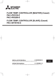
▪ Lift the unit preferably with a crane and 2 belts of at least 8 m long
as shown in the figure below. Always use protectors to prevent
belt damage and pay attention to the position of the unit's centre
of gravity.
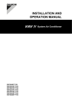
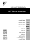
3.3
To remove the accessories from
the outdoor unit
8~12 HP
14~20 HP
b
d
b
a
d
d
c
c
Make sure that all accessories are available in the unit.
b
a
1×
c
1×
No.
a
b
c
d
1
2
3
11
12
13
21
22
23
4
1×
6
7
8
14
15
24
25
9
10
16
17
26
27
18
19
20
28
29
30
38
39
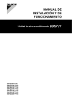
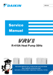
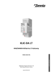
BE SURE TO FILL OUT THE BLANKS, WHICH ARE NEEDED FOR AFTER-SALE SERVICES.
1. CALCULATION OF ADDITIONAL REFRIGERANT CHARGING AMOUNT
CALCULATE THE ADDITIONAL REFRIGERANT CHARGING AMOUNT BASED ON THE FORMULA BELOW BEFORE CHARGING.
WHEN RE-CHARGING TOTAL AMOUNT OF REFRIGERANT , CHARGE THE TOTAL OF THE AMOUNT CHARGED AT
SHIPMENT (INDICATED ON THE MACHINE NAMEPLATE) AND THE ADDITIONAL AMOUNT SHOWN AS FOLLOWS :
MODELNAME
Packaging material
Belt sling
Opening
Protector
INSTALLATION
SITE
No.
MODELNAME
INSTALLATION
SITE
No.
ADDITIONAL CHARGING
OUTDOOR AMOUNT
UNIT
kg
MODELNAME
INSTALLATION
SITE
No.
TOTAL LENGTH OF LIQUID
PIPE SIZE O22.2 x 0.37
(m) x 0.37
TOTAL LENGTH OF LIQUID
PIPE SIZE O12.7 x 0.12
31
32
34
33
35
36
37
40
(m) x 0.12
TOTAL LENGTH OF LIQUID
PIPE SIZE O19.1 x 0.26
(m) x 0.26
TOTAL LENGTH OF LIQUID
PIPE SIZE O9.5 x 0.059
(m) x 0.059
TOTAL LENGTH OF LIQUID
PIPE SIZE O15.9 x 0.18
(m) x 0.18
TOTAL LENGTH OF LIQUID
PIPE SIZE O6.4 x 0.022
(m) x 0.022
MODELNAME
INSTALLATION
SITE
No.
41
42
43
45
44
46
47
48
49
58
59
No.
No.
kg
ONLY FOR RYYQ8~20 MODELS
RYYQ8~12 RYYQ14-16 RYYQ18-20
1.1
0.9
1.3
DATE
AMOUNT
51
52
53
54
56
55
57
RESULT LEAK CHECK
60
MODELNAME
DATE
61
62
63
AMOUNT
64
RESULT LEAK CHECK
MODELNAME
INSTALLATION
SITE
DATE
AMOUNT
2. RECORD FOR SETTINGS (CONTENTS SEE INSTALLATION MANUAL)
SETTING
Total indoor unit
capacity connection
kg ratio (CR)
8HP 10-12HP 14-16HP 18-20HP
0.5
0
0
Total indoor unit capacity 50%< CR < 105% 0
1.0
0.5
when piping length <30m105%< CR < 130% 0.5
0.5
0.5
0
0
50%< CR < 70% 0
1.0
0.5
0.5
Total indoor unit capacity 70%< CR < 85% 0.3
1.5
1
1
when piping length >30m 85%< CR < 105% 0.7
2.0
1.5
1.5
105%< CR < 130% 1.2
2. RECORD OF ADDITIONAL REFRIGERANT CHARGE AMOUNT AND RESULT OF LEAK CHECK OPERATION
50
MODELNAME
INSTALLATION
SITE
INSTALLATION
SITE
1×
REQUEST FOR THE INDICATION OF ADDITIONAL REFRIGERANT CHARGING AND LEAK DETECTION OPERATION RESULT
BE SURE TO FILL OUT THE BLANKS, WHICH ARE NEEDED FOR AFTER-SALE SERVICES.
5
e
d
1×
REQUEST FOR THE INDICATION OF INSTALLATION INFORMATION
1. RECORD OF INDOOR UNIT MODEL AND INSTALLATION SITE
VALUE
REMARK
DATE
SETTING
VALUE
REMARK
RESULT LEAK CHECK
DATE
DATE
AMOUNT
RESULT LEAK CHECK
3. RECORD OF INSTALLATION DATE
DAY
MONTH
YEAR
4. MODEL NAME
3. FOR DETAILS CONCERNING PIPING SELECTION AND CALCULATION OR HOW TO OPERATE THE LEAK DETECTION FUNCTION, PLEASE REFER TO THE INSTALLATION MANUAL.
5. MANUFACTURING NUMBER
4. AFTER FILLING IN THIS TABLE, PLEASE PUT IT ON THE SWITCH BOX COVER.
6. AFTER EQUIPPING, PLEASE PUT IT ON THE BACK SIDE OF THE FRONT PLATE.
3P328191-1
f
NOTICE
3P328192-1
g
1×
1×
Use a belt sling of ≤20 mm wide that adequately bears the
weight of the unit.
▪ A forklift can only be used for transport as long as the unit remains
on its pallet as shown above.
3.2
a
b
c
d
e
f
g
To unpack the outdoor unit
Relief the unit from its packing material:
▪ Take care not to damage the unit when removing the shrink foil
with a cutter.
▪ Remove the 4 bolts fixing the unit to its pallet.
WARNING
Accessory pipes: Diameters
Accessory pipes (mm)
Tear apart and throw away plastic packaging bags so that
nobody, especially children, can play with them. Possible
risk: suffocation.
8~12 HP
3.4
General safety precautions
Installation manual and operation manual
Additional refrigerant charge label
Installation information sticker
Fluorinated greenhouse gases label
Multilingual fluorinated greenhouse gases label
Piping accessory bag
14~20 HP
HP
Øb
Øa
Gas pipe
8
▪ Front connection
10
25.4
22.2
12
25.4
28.6
ID Øa
ID Øb
19.1
14
▪ Bottom connection
ID Øa
OD Øb
16
18
20
8
Liquid pipe
▪ Front connection
10
ID Øb
12
ID Øa
9.52
9.52
14
12.7
12.7
16
▪ Bottom connection
ID Øb
ID Øa
12.7
15.9
20
(a)
Equaliser pipe
8
▪ Front connection
10
ID Øa
ID Øb
12
▪ Bottom connection
16
ID Øa
OD Øb
(a)
RYYQ+RYMQ+RXYQ8~20T7Y1B
VRV IV system air conditioner
4P3704751 – 2014.02
18
19.1
19.1
22.2
25.4
28.6
14
18
20
Only for RYMQ models.
Installer and user reference guide
7
4 About the units and options
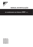
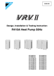
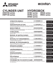
To remove the transportation stay
3.5
Model identification
Example: R Y Y Q 18 T7 Y1 B
Only for 14~20 HP
Code
NOTICE
If the unit is operated with the transportation stay attached,
abnormal vibration or noise may be generated.
Explanation
R
Outdoor air cooled
Y
Y=Heat pump (continuous heating)
X=Heat pump (no continuous heating)
The yellow transportation stay installed over the compressor leg for
protecting the unit during transport must be removed. Proceed as
shown in the figure and procedure below.
Y=Pair module only(a)
Y
M=Multi module only
Slightly loosen the fixing nut (A).
Q
Refrigerant R410A
2
Remove the transportation stay (B) as shown in the figure
below.
18
Capacity index
T7
VRV IV series
3
Tighten the fixing nut (A) again (12.3 N•m).
Y1
Power supply: 3N~, 380415 V, 50 Hz
1
B
European market
(a)
4.3
2
3 (12.3 N·m)
1
About the outdoor unit
This installation manual concerns the VRV IV, full inverter driven,
heat pump system.
Model line up:
A
B
4
About the units and options
Model
RYYQ8~20
(a)
Overview: About the units and
options
This chapter contains information about:
▪ Identification of the outdoor unit.
▪ Where the outdoor unit fits in the system layout.
▪ With which indoor units and options you can combine the outdoor
units.
▪ Which outdoor units have to be used as standalone units, and
which outdoor units can be combined.
4.2
Identification label: Outdoor unit
Description
Single continuous heating model.
RYYQ22~54(a)
Multi continuous heating model (consisting
of 2 or 3 RYMQ modules).
RXYQ8~20
Single noncontinuous heating model.
RXYQ22~54
Multi noncontinuous heating model
(consisting of 2 or 3 RXYQ modules).
(a)
4.1
For RXYQ, there is no restriction on use as multi module.
The RYYQ models provide continuous comfort during
defrost operation.
Depending on the type of outdoor unit which is chosen, some
functionality will or will not exist. It will be indicated throughout this
installation manual and brought to your attention. Certain features
have exclusive model rights.
These units are intended for outdoor installation and aimed for heat
pump applications including air to air and air to water applications.
These units have (in single use) heating capacities ranging from 25
to 63 kW and cooling capacities rating from 22.4 to 56 kW. In multi
combination the heating capacity can go up till 168 kW and in
cooling till 150 kW.
The outdoor unit is designed to work in heating mode at ambient
temperatures from –20°C WB to 15.5°C WB and in cooling mode at
ambient temperatures from –5°C DB to 43°C DB.
Location
8~12 HP
Installer and user reference guide
8
14~20 HP
RYYQ+RYMQ+RXYQ8~20T7Y1B
VRV IV system air conditioner
4P3704751 – 2014.02
4 About the units and options
4.4
4.5.3
System layout
Possible standalone outdoor units
NOTICE
Noncontinuous heating
Continuous heating
Design of the system must not be done at temperatures
below –15°C.
RXYQ8
RYYQ8
INFORMATION
RXYQ10
RYYQ10
RXYQ12
RYYQ12
RXYQ14
RYYQ14
RXYQ16
RYYQ16
RXYQ18
RYYQ18
RXYQ20
RYYQ20
Not all combinations of indoor units are allowed, for
guidance, see "4.5.2 Possible combinations of indoor
units" on page 9.
a
i
Possible combinations of outdoor units
Possible standard combinations of outdoor units
b
c
d
c
c
e
c
▪ RXYQ22~54 consists of 2 or 3 RXYQ8~20 units.
▪ RYYQ22~54 consists of 2 or 3 RYMQ8~20 units.
f
▪ RYYQ8~20 units cannot be combined.
g
a
b
c
d
e
f
g
h
i
4.5
4.5.1
g
g
h
g
g
VRV IV Heat pump outdoor unit
Refrigerant piping
VRV direct expansion (DX) indoor unit
VRV LT Hydrobox (HXY080/125)
BP box (required to connect Residential Air (RA) or Sky Air
(SA) direct expansion (DX) indoor units)
Residential Air (RA) direct expansion (DX) indoor units)
User interface (dedicated depending on indoor unit type)
User interface (wireless, dedicated depending on indoor
unit type)
Cool/Heat changeover remote control switch
Combining units and options
About combining units and options
NOTICE
To be sure your system setup (outdoor unit+indoor unit(s))
will work, you have to consult the latest technical
engineering data for VRV IV heat pump.
▪ RYMQ8~20 units cannot be used as standalone outdoor unit.
Noncontinuous heating
Continuous heating
RXYQ22 = RXYQ10 + 12
RYYQ22 = RYMQ10 + 12
RXYQ24 = RXYQ8 + 16
RYYQ24 = RYMQ8 + 16
RXYQ26 = RXYQ12 + 14
RYYQ26 = RYMQ12 + 14
RXYQ28 = RXYQ12 + 16
RYYQ28 = RYMQ12 + 16
RXYQ30 = RXYQ12 + 18
RYYQ30 = RYMQ12 + 18
RXYQ32 = RXYQ16 + 16
RYYQ32 = RYMQ16 + 16
RXYQ34 = RXYQ16 + 18
RYYQ34 = RYMQ16 + 18
RXYQ36 = RXYQ16 + 20
RYYQ36 = RYMQ16 + 20
RXYQ38 = RXYQ8 + 10 + 20
RYYQ38 = RYMQ8 + 10 + 20
RXYQ40 = RXYQ10 + 12 + 18
RYYQ40 = RYMQ10 + 12 + 18
RXYQ42 = RXYQ10 + 16 + 16
RYYQ42 = RYMQ10 + 16 + 16
RXYQ44 = RXYQ12 + 16 + 16
RYYQ44 = RYMQ12 + 16 + 16
RXYQ46 = RXYQ14 + 16 + 16
RYYQ46 = RYMQ14 + 16 + 16
RXYQ48 = RXYQ16 + 16 + 16
RYYQ48 = RYMQ16 + 16 + 16
The VRV IV heat pump system can be combined with several types
of indoor units and is intended for R410A use only.
RXYQ50 = RXYQ16 + 16 + 18
RYYQ50 = RYMQ16 + 16 + 18
RXYQ52 = RXYQ16 + 18 + 18
RYYQ52 = RYMQ16 + 18 + 18
For an overview which units are available you can consult the
product catalogue for VRV IV.
RXYQ54 = RXYQ18 + 18 + 18
RYYQ54 = RYMQ18 + 18 + 18
An overview is given indicating the allowed combinations of indoor
units and outdoor units. Not all combinations are allowed. They are
subject to rules (combination between outdoorindoor, single outdoor
unit use, multiple outdoor unit use, combinations between indoor
units, etc.) mentioned in the technical engineering data.
4.5.4
4.5.2
Refrigerant branching kit
Possible combinations of indoor units
In general following type of indoor units can be connected to a VRV
IV heat pump system. The list is nonexhaustive and is depending
on both outdoor unit model and indoor unit model combinations.
Possible options for the outdoor unit
INFORMATION
Refer to the technical engineering data for the latest option
names.
Description
Refnet header
KHRQ22M64H
▪ VRV direct expansion (DX) indoor units (air to air applications).
▪ SA/RA (Sky Air/Residential Air) direct expansion (DX) indoor units
(air to air applications). Further referred to as RA DX indoor units.
Model name
KHRQ22M29H
KHRQ22M75H
Refnet joint
KHRQ22M20T
KHRQ22M29T9
▪ Hydrobox (air to water applications): HXY080/125 series only.
KHRQ22M64T
▪ AHU (air to air applications): EKEXVkit+EKEQbox are required,
depending on application.
KHRQ22M75T
▪ Aircurtain (air to air applications): CYQ/CAV (Biddle) series,
depending on application.
RYYQ+RYMQ+RXYQ8~20T7Y1B
VRV IV system air conditioner
4P3704751 – 2014.02
For the selection of the optimal branching kit, please refer to
"5.3.3 To select refrigerant branch kits" on page 14.
Installer and user reference guide
9
5 Preparation
Outdoor multi connection piping kit
Model name
Number of outdoor units
2
BHFQ22P1007
3
BHFQ22P1517
▪ Select a place where the rain can be avoided as much as
possible.
▪ Select the location of the unit in such a way that the sound
generated by the unit does not disturb anyone, and the location is
selected according the applicable legislation.
Cool/heat selector
In order to control the cooling or heating operation from a central
location, the following option can be connected:
Description
Model name
Cool/heat change over switch
KRC1926A
Cool/heat change over PCB
BRP2A81
With optional fixing box for the
switch
KJB111A
Do NOT install the unit in the following places:
▪ In potentially explosive atmospheres.
▪ In places where there is machinery that emits electromagnetic
waves. Electromagnetic waves may disturb the control system,
and cause malfunction of the equipment.
▪ In places where there is a risk of fire due to the leakage of
flammable gases (example: thinner or gasoline), carbon fibre,
ignitable dust.
External control adaptor (DTA104A61/62)
To instruct specific operation with an external input coming from a
central control the external control adaptor can be used. Instructions
(group or individual) can be instructed for low noise operation and
power consumption limitation operation.
PC configurator cable (EKPCCAB)
For VRV IV heat pump system it is also possible to make several
commissioning field settings through a personal computer interface.
For this option EKPCCAB is required which is a dedicated cable to
communicate with the outdoor unit. The user interface software is
available on http://www.daikineurope.com/supportandmanuals/
softwaredownloads/.
▪ In places where corrosive gas (example: sulphurous acid gas) is
produced. Corrosion of copper pipes or soldered parts may cause
the refrigerant to leak.
▪ In places where a mineral oil mist, spray or vapour may be
present in the atmosphere. Plastic parts may deteriorate and fall
off or cause water leakage.
▪ In places where the air contains high levels of salt such as that
near the ocean.
NOTICE
This is a class A product. In a domestic environment this
product may cause radio interference in which case the
user may be required to take adequate measures.
Heater tape kit
NOTICE
To keep the drain holes free in cold climates with high humidity, you
can install a heater tape kit. If you do so, you also have to install the
heater tape PCB kit.
Description
The equipment described in this manual may cause
electronic noise generated from radiofrequency energy.
The equipment complies to specifications that are
designed to provide reasonable protection against such
interference. However, there is no guarantee that
interference will not occur in a particular installation.
Model name
Heater tape kit for 8~12 HP
EKBPH012T
Heater tape kit for 14~20 HP
EKBPH020T
Heater tape PCB kit
EKBPHPCBT
It is therefore recommended to install the equipment and
electric wires keeping proper distances away from stereo
equipment, personal computers, etc.
See also: "5.2.2 Additional installation site requirements of the
outdoor unit in cold climates" on page 11.
c
5
Preparation
5.1
Overview: Preparation
This chapter describes what you have to do and know before going
onsite.
It contains information about:
▪ Preparing the installation site
▪ Preparing the refrigerant piping
▪ Preparing the electrical wiring
5.2
Preparing installation site
5.2.1
Installation site requirements of the
outdoor unit
▪ Provide sufficient space around the unit for servicing and air
circulation.
▪ Make sure the installation site withstands the unit's weight and
vibration.
▪ Make sure the area is well ventilated.
b
e
c
(mm)
b
d
d
f
a
a
b
c
d
e
f
Personal computer or radio
Fuse
Earth leakage protector
User interface
Indoor unit
Outdoor unit
In places with weak reception, keep distances of 3 m or more to
avoid electromagnetic disturbance of other equipment and use
conduit tubes for power and transmission lines.
CAUTION
Appliance not accessible to the general public, install it in a
secured area, protected from easy access.
This unit, both indoor and outdoor, is suitable for
installation in a commercial and light industrial
environment.
▪ When installing, take strong winds, typhoons or earthquakes into
account, improper installation may result in the unit turning over.
▪ Make sure the unit is level.
Installer and user reference guide
10
RYYQ+RYMQ+RXYQ8~20T7Y1B
VRV IV system air conditioner
4P3704751 – 2014.02
5 Preparation
▪ Take care that in the event of a water leak, water cannot cause
any damage to the installation space and surroundings.
NOTICE
When operating the unit in a low outdoor ambient
temperature with high humidity conditions, make sure to
take precautions to keep the drain holes of the unit free by
using proper equipment.
▪ When installing the unit in a small room, take measures in order to
keep the refrigerant concentration from exceeding allowable
safety limits in the event of a refrigerant leak, refer to "About
safety against refrigerant leaks" on page 11.
In heating:
20
CAUTION
Excessive refrigerant concentrations in a closed room can
lead to oxygen deficiency.
15.5
15
10
▪ Be sure that the air inlet of the unit is not positioned towards the
main wind direction. Frontal wind will disturb the operation of the
unit. If necessary, use a screen to block the wind.
TAO (°C WB)
5
▪ Ensure that water cannot cause any damage to the location by
adding water drains to the foundation and prevent water traps in
the construction.
5.2.2
a
b
0
–5
–10
Additional installation site requirements
of the outdoor unit in cold climates
–15
–20
NOTICE
When operating the unit in a low outdoor ambient
temperature, be sure to follow the instructions described
below.
10
15
20
25 27 30
TAI (°C DB)
In heavy snowfall areas it is very important to select an installation
site where the snow will NOT affect the unit. If lateral snowfall is
possible, make sure that the heat exchanger coil is NOT affected by
the snow. If necessary, install a snow cover or shed and a pedestal.
a Warming up operation range
b Operation range
TAI Ambient indoor temperature
TAO Ambient outdoor temperature
If the unit has to operate for 5 days in this area with
high humidity (>90%), Daikin recommends to install the
optional heater tape kit (EKBPH012T or EKBPH020T) to
keep the drain holes free. If you do so, you also have to
install the heater tape PCB kit (EKBPHPCBT).
5.2.3
Securing safety against refrigerant leaks
About safety against refrigerant leaks
The installer and system specialist shall secure safety against
leakage according to local regulations or standards. The following
standards may be applicable if local regulations are not available.
INFORMATION
This system uses R410A as refrigerant. R410A itself is an entirely
safe nontoxic, noncombustible refrigerant. Nevertheless care must
be taken to ensure that air conditioning facilities are installed in a
room which is sufficiently large. This assures that the maximum
concentration level of refrigerant gas is not exceeded, in the unlikely
event of major leak in the system and this in accordance to the local
applicable regulations and standards.
For instructions on how to install the snow cover, contact
your dealer.
About the maximum concentration level
NOTICE
The maximum charge of refrigerant and the calculation of the
maximum concentration of refrigerant is directly related to the
humanly occupied space in to which it could leak.
When installing the snow cover, do NOT obstruct the air
flow of the unit.
The unit of measurement of the concentration is kg/m3 (the weight in
kg of the refrigerant gas in 1 m3 volume of the occupied space).
Compliance to the local applicable regulations and standards for the
maximum allowable concentration level is required.
According to the appropriate European Standard, the maximum
allowed concentration level of refrigerant to a humanly space for
R410A is limited to 0.44 kg/m3.
RYYQ+RYMQ+RXYQ8~20T7Y1B
VRV IV system air conditioner
4P3704751 – 2014.02
Installer and user reference guide
11
5 Preparation
3
a
b
a
b
Direction of the refrigerant flow
Room where refrigerant leak has occurred (outflow of all
the refrigerant from the system)
Pay special attention to places, such as basements etc., where
refrigerant can stay, since refrigerant is heavier than air.
Formula
A/B≤C
A
Total volume of refrigerant in the refrigerant
system
B
Size (m3) of smallest room in which there is an
indoor unit installed
C
Maximum concentration level (kg/m3)
4
To check the maximum concentration level
Check the maximum concentration level in accordance with steps 1
to 4 below and take whatever action is necessary to comply.
1
Calculate the amount of refrigerant (kg) charged to each system
separately.
Formula
A+B=C
A
Amount of refrigerant in a single unit system
(amount of refrigerant with which the system is
charged before leaving the factory)
B
Additional charging amount (amount of
refrigerant added locally in accordance with the
length or diameter of the refrigerant piping)
C
Total amount of refrigerant (kg) in the system
NOTICE
Where a single refrigerant facility is divided into 2 entirely
independent refrigerant systems, use the amount of
refrigerant with which each separate system is charged.
2
A
Calculate the volume of the room (m3) where the indoor unit is
installed. In a case such as the following, calculate the volume
of (A), (B) as a single room or as the smallest room.
Where there are no smaller room divisions:
Calculate the refrigerant density using the results of the
calculations in steps 1 and 2 above. If the result of the above
calculation exceeds the maximum concentration level, a
ventilation opening to the adjacent room shall be made.
Calculate the refrigerant density taking the volume of the room
where the indoor unit is installed and the adjacent room. Install
ventilation openings in the door of adjacent rooms until the
refrigerant density is smaller than the maximum concentration
level.
5.3
Preparing refrigerant piping
5.3.1
Refrigerant piping requirements
NOTICE
The refrigerant R410A requires strict cautions for keeping
the system clean, dry and tight.
▪ Clean and dry: foreign materials (including mineral oils
or moisture) should be prevented from getting mixed
into the system.
▪ Tight: R410A does not contain any chlorine, does not
destroy the ozone layer, and does not reduce earth's
protection against harmful ultraviolet radiation. R410A
can contribute slightly to the greenhouse effect if it is
released. Therefore we should take special attention to
check the tightness of the installation.
NOTICE
Piping and other pressure containing parts shall comply
with the applicable legislation and shall be suitable for
refrigerant. Use phosphoric acid deoxidised seamless
copper for refrigerant.
▪ Foreign materials inside pipes (including oils for fabrication) must
be ≤30 mg/10 m.
▪ Temper grade: use piping with temper grade in function of the
pipe diameter as listed in table below.
Pipe Ø (mm)
B
Where there is a room division, but there is an opening
between the rooms sufficiently large to permit a free flow of air
back and forth.
a
Temper grade of piping material
≤15.9
O (annealed)
≥19.1
1/2H (half hard)
▪ All piping lengths and distances have been taken into
consideration (see "5.3.4 About the piping length" on page 15).
b
a Opening between the rooms
b Partition (Where there is an opening without a door or where
there are openings above and below the door which are each
equivalent in size to 0.15% or more of the floor area.)
Installer and user reference guide
12
RYYQ+RYMQ+RXYQ8~20T7Y1B
VRV IV system air conditioner
4P3704751 – 2014.02
5 Preparation
To select the piping size
5.3.2
Determine the proper size referring to following tables and reference
figure (only for indication).
E: Piping between refrigerant branch kit and
indoor unit
Pipe size for direct connection to indoor unit must be the same as
the connection size of the indoor unit (in case indoor unit is VRV DX
indoor or Hydrobox).
Indoor unit capacity
index
A
a
D
B
C y
x
B
B
F
b
3
2
1,2
3
4,5
a,b
x,y
4
15~50
12.7
6.4
15.9
9.5
200
19.1
250
22.2
5
a
b
a
b
c
d
e
Choose from the following table in accordance with the outdoor unit
total capacity type, connected downstream.
Piping outer diameter size (mm)
Gas pipe
Liquid pipe
8
19.1
9.5
10
22.2
9.5
12~16
28.6
12.7
18~22
28.6
15.9
24
34.9
15.9
26~34
34.9
19.1
36~54
41.3
19.1
D: Piping between refrigerant branch kits
Choose from the following table in accordance with the indoor unit
total capacity type, connected downstream. Do not let the
connection piping exceed the refrigerant piping size chosen by the
general system model name.
Piping outer diameter size (mm)
Gas pipe
Liquid pipe
<150
15.9
9.5
150≤x<200
19.1
200≤x<290
22.2
290≤x<420
28.6
420≤x<640
12.7
15.9
640≤x<920
34.9
≥920
41.3
19.1
Example:
▪ Downstream capacity for E=capacity index of unit 1
▪ Downstream capacity for D=capacity index of unit 1+capacity
index of unit 2
c
e
d
A, B, C: Piping between outdoor unit and (first)
refrigerant branch kit
Indoor unit capacity
index
Liquid pipe
▪ When the equivalent pipe length between outdoor and indoor
units is 90 m or more, the size of the main pipes (both gas side
and liquid side) must be increased. Depending on the length of the
piping, the capacity may drop, but even in such a case it is
possible to increase the size of the main pipes.
VRV DX indoor unit
BP box
RA DX indoor unit
Indoor branch kit
Outdoor multi connection kit
Outdoor unit
capacity type (HP)
Gas pipe
63~125
G
E
1
Piping outer diameter size (mm)
Outdoor unit
Main pipes
Increase
First refrigerant branch kit
Indoor unit
Size up
HP class
Piping outer diameter size (mm)
Gas pipe
Liquid pipe
8
19.1 → 22.2
9.5 → 12.7
10
22.2 → 25.4(a)
12+14
28.6(b)
16
12.7 → 15.9
28.6 → 31.8
(a)
18~22
15.9 → 19.1
24
34.9(b)
26~34
34.9 → 38.1(a)
36~54
(a)
(b)
41.3
19.1 → 22.2
(b)
If size is NOT available, increase is NOT allowed.
Increase is NOT allowed.
▪ The pipe thickness of the refrigerant piping shall comply with the
applicable legislation. The minimal pipe thickness for R410A
piping must be in accordance with the table below.
Pipe Ø (mm)
Minimal thickness t (mm)
6.4/9.5/12.7
0.80
15.9
0.99
19.1/22.2
0.80
28.6
0.99
34.9
1.21
41.3
1.43
▪ In case the required pipe sizes (inch sizes) are not available, it is
also allowed to use other diameters (mm sizes), taken the
following into account:
▪ Select the pipe size nearest to the required size.
▪ Use the suitable adapters for the changeover from inch to mm
pipes (field supply).
▪ The additional refrigerant calculation has to be adjusted as
mentioned in "6.7.3 To determine the additional refrigerant
amount" on page 27.
RYYQ+RYMQ+RXYQ8~20T7Y1B
VRV IV system air conditioner
4P3704751 – 2014.02
Installer and user reference guide
13
5 Preparation
F: Piping between refrigerant branch kit and BP
unit
Pipe size for direct connection on BP unit must be based on the total
capacity of the connected indoor units (only in case RA DX indoor
units are connected).
Total capacity index
of connected indoor
units
Liquid pipe
20~62
12.7
6.4
63~149
15.9
9.5
150~208
19.1
Example:
Downstream capacity for F=capacity index of unit 4+capacity index
of unit 5
G: Piping between BP unit and RA DX indoor unit
▪ How to choose an outdoor multi connection piping kit. Choose
from the following table in accordance with the number of outdoor
units.
Piping outer diameter size (mm)
Gas pipe
Liquid pipe
20, 25, 30
9.5
6.4
50
12.7
9.5
15.9
To select refrigerant branch kits
Refrigerant refnets
For piping example, refer to "5.3.2 To select the piping size" on
page 13.
▪ When using refnet joints at the first branch counted from the
outdoor unit side, choose from the following table in accordance
with the capacity of the outdoor unit (example: refnet joint a).
Outdoor unit capacity type
(HP)
2 pipes
8~10
KHRQ22M29T9
12~22
KHRQ22M64T
24~54
KHRQ22M75T
▪ For refnets joints other than the first branch (example refnet joint
b), select the proper branch kit model based on the total capacity
index of all indoor units connected after the refrigerant branch.
Indoor unit capacity index
Branch kit name
2
BHFQ22P1007
3
BHFQ22P1517
The RYYQ22~54 models, consisting of two or three RYMQ modules,
require a 3pipe system. There is an additional equalising pipe for
such modules (in addition to the conventional gas and liquid piping).
This equalising pipe does not exist for RYYQ8~20 or RXYQ8~54
units.
The equalising pipe connections for the different RYMQ modules are
mentioned in below table.
Equalising pipe Ø (mm)
8
19.1
10~16
22.2
18~20
28.6
Deciding the equalising pipe diameter:
60
71
Number of outdoor units
RYMQ
Only in case RA DX indoor units are connected.
5.3.3
Maximum 8 branches can be connected to a header.
Piping outer diameter size (mm)
Gas pipe
Indoor unit capacity
index
INFORMATION
2 pipes
<200
KHRQ22M20T
200≤x<290
KHRQ22M29T9
290≤x<640
KHRQ22M64T
≥640
KHRQ22M75T
▪ In case of 3 multi units: the connection diameter of outdoor to T
joint has to be kept.
▪ In case of 2 multi units: the connection pipe has to have the
largest diameter.
There is never a connection of the equalising pipe with the indoor
units.
Example: (free multi combination)
RYMQ8+RYMQ12+RYMQ18. Largest connection is Ø28.6
(RYMQ18); Ø22.2 (RYMQ12) and Ø19.1 (RYMQ8). In figure below
only equalising pipe is shown.
Ø28.6 mm
Ø22.2 mm
Ø19.1 mm
INFORMATION
Reducers or Tjoints are field supplied.
NOTICE
Refrigerant branch kits can only be used with R410A.
▪ Concerning refnet headers, choose from the following table in
accordance with the total capacity of all the indoor units connected
below the refnet header.
Indoor unit capacity index
2 pipes
<200
KHRQ22M29H
200≤x<290
290≤x<640
KHRQ22M64H(a)
≥640
KHRQ22M75H
(a)
If the pipe size above the refnet header is Ø34.9 or more,
KHRQ22M75H is required.
Installer and user reference guide
14
RYYQ+RYMQ+RXYQ8~20T7Y1B
VRV IV system air conditioner
4P3704751 – 2014.02
5 Preparation
About the piping length
5.3.4
Example
Make sure to perform the piping installation within the range of the
maximum allowable pipe length, allowable level difference and
allowable length after branching as indicated below. Three patterns
will be discussed, including VRV DX indoor units combined with
Hydrobox units or RA DX indoor units.
Term
s
r
u
t
b
A
c
d
B
C
i
1
2
r
u
Pipe length between outdoor and indoor
units.
H2
Difference in height between indoor and
indoor units.
H3
Difference in height between outdoor and
outdoor units.
H4
Difference in height between outdoor and
BP unit.
H5
Difference in height between BP unit and
BP unit.
H6
Difference in height between BP unit and
RA DX indoor unit.
c
1
Single outdoor
Branch with refnet joint
c
1
d
C
e
D
j
2
E
k
3
g
f
F
l
4
G
m
5
n
6
p
d
7
H2
b
1
c
2
A
H1
d
e
2
B
b
3
4
f
5
g
6
j
7
8
a
d
h
d
3
B
3
4
f
5
g
6
j
H2
h
7
8
H1
k
Multi outdoor
t
s
Branch with refnet
header
H3
H1
e
4
5
f
6
g
7
h
i
8
With standard multi
layout
s
t
e
4
5
f
6
g
▪ Between outdoor and indoor units (standard multi/free multi
combinations)
Actual piping
length
h
7
H2
165 m/135 m
Example 1.1
▪ unit 8: a+b+c+d+e+f+g+p≤165 m
Example 1.2
Single outdoor
▪ unit 6: a+b+h≤165 m
Branch with refnet joint
and refnet header
▪ unit 8: a+i+k≤165 m
Example 1.3
H2
▪ unit 8: a+i≤165 m
Branch with refnet
header
2
Branch with refnet joint
and refnet header
H3
Example 2.1
H1
c
Multi outdoor
u
Single outdoor
a
1
3
r
k
Example 1.3
b
8
Example 3
8
i
a
1
e
2
r
u
H1
Example 1.2
c
7
Indoor unit
Refnet joint
Refnet header
Outdoor multi connection piping kit
Description
Example 1.1
i
6
H1
Maximum allowable length
Example
B
p
n
Example 2.3
If the system capacity is >20 HP, reread "the first outdoor
branch as seen from the indoor unit".
Assume equivalent piping length of refnet joint=0.5 m and
refnet header=1 m (for calculation purposes of equivalent
piping length, not for refrigerant charge calculations).
System setup
h
5
A
For system only containing VRV DX indoor units:
A
t
s
a
Piping length: VRV DX only
b
G
m
b
Total piping length from the outdoor to all
indoor units.
Difference in height between outdoor and
indoor units.
a
4
g
F
l
(a)
H1
(b)
3
f
E
k
Example 2.2
(a)
Total piping length
(a)
e
D
j
Pipe length between outdoor(a) and indoor
units.
Equivalent piping
length(b)
5.3.5
a
H3
Definition
Actual piping length
Multi outdoor
Branch with refnet joint
h
Definitions
Description
Example 2.1
i
8
▪ unit 8: a+b+c+d+e+f+g+p≤135 m
Equivalent length 190 m/160 m
Total piping
length
1000 m/500 m
Example 1.1
▪ a+b+c+d+e+f+g+h+i+j+k+l+m+n+p≤1000 m
Example 2.1
▪ a+b+c+d+e+f+g+h+i+j+k+l+m+n+p≤500 m
RYYQ+RYMQ+RXYQ8~20T7Y1B
VRV IV system air conditioner
4P3704751 – 2014.02
Installer and user reference guide
15
5 Preparation
▪ Between outdoor branch and outdoor unit (only in case >20 HP)
Conditions:
Actual piping
length
a
10 m
The piping length between all indoor to the nearest branch kit is
≤40 m.
Example 3
Example: h, i, j … p≤40 m
▪ r, s, t≤10 m; u≤5 m
b
Equivalent length 13 m
It is necessary to increase the pipe size of the gas and liquid
piping if the pipe length between the first and the final branch kit
is over 40 m.
Maximum allowable height difference
H1
≤50 m (40 m) (if outdoor is located below indoor units)
If the increased pipe size is larger than the pipe size of the main
pipe, then the pipe size of the main pipe has to be increased as
well.
Conditional extension up till 90 m is possible without
additional option kit:
Increase the pipe size as follows:
9.5 → 12.7; 12.7 → 15.9; 15.9 → 19.1; 19.1 → 22.2; 22.2 →
25.4(a); 28.6 → 31.8(a); 34.9 → 38.1(a)
▪ In case the outdoor location is higher than indoor:
extension is possible up till 90 m and following
2 conditions must be fulfilled:
▪ Liquid piping size up (see table "Size up" in "E: Piping
between refrigerant branch kit and indoor unit" on page
13).
(a) If available on the site. Otherwise it cannot be increased.
Example: unit 8: b+c+d+e+f+g+p≤90 m and b+c+d+e+f+g
>40 m; increase the pipe size of b, c, d, e, f, g.
c
When the piping size is increased (step b), the piping length
has to be counted as double (except for the main pipe and the
pipes that are not increased in pipe size).
▪ Dedicated setting on outdoor unit is required (see [249]
in "7.2.8 Mode 2: Field settings" on page 40).
The total piping length has to be within limitations (see table
above).
▪ In case the outdoor location is lower than indoor:
extension is possible up till 90 m and following
6 conditions must be fulfilled:
Example: a+b×2+c×2+d×2+e×2+f×2+g×2+h+i+j+k+l+m+n
+p≤1000 m (500 m).
▪ 40~60 m: minimum connection ratio connected: 80%.
▪ 60~65 m: minimum connection ratio connected: 90%.
d
The piping length difference between the nearest indoor from
first branch to the outdoor unit and farthest indoor to the
outdoor unit is ≤40 m.
▪ 65~80 m: minimum connection ratio connected: 100%.
▪ 80~90 m: minimum connection ratio connected: 110%.
▪ Liquid piping size up (see table "Size up" in "E: Piping
between refrigerant branch kit and indoor unit" on page
13).
▪ Dedicated setting on outdoor unit is required (see [235]
in "7.2.8 Mode 2: Field settings" on page 40).
H2
≤30 m
H3
≤5 m
Example: The farthest indoor unit 8. The nearest indoor unit 1
→ (a+b+c+d+e+f+g+p)–(a+h)≤40 m.
Piping length: VRV DX and Hydrobox
5.3.6
For system containing VRV DX indoor units and Hydrobox:
System setup
Maximum allowable length after branch
The pipe length from the first refrigerant branch kit to the indoor unit
≤40 m.
b
a
A
Example 1.1: unit 8: b+c+d+e+f+g+p≤40 m
c
B
h
Example 1.2: unit 6: b+h≤40 m, unit 8: i+k≤40 m
d
2
3
1
b
A
c
B
h
1
d
C
i
2
1
2
3
e
D
j
3
f
E
k
4
G
m
5
n
6
p
7
H2
H1
8
Branch with refnet joint
and refnet header
i
a
A
g
F
l
5
Outdoor units
Refnet joints (A~G)
Indoor unit (1~8)
c
G
m
6
p H1
n
7
H2
d
1
Installer and user reference guide
e
2
B
b
3
4
f
5
g
6
j
7
8
k
H2
h
Branch with refnet
header
Example 3
8
a
H1
b
1
c
2
d
1~7
8
16
F
l
4
H1
a
g
f
E
k
Example 2
However, extension is possible if all below conditions are met. In this
case limitation can be extended up to 90 m.
3
e
D
j
Example 1.3: unit 8: i≤40 m
2
Description
Branch with refnet joint
C
i
1
Example
Example 1
3
e
4
5
f
6
g
h
7
H2
i
8
VRV DX indoor units
Hydrobox unit (HXY080/125)
RYYQ+RYMQ+RXYQ8~20T7Y1B
VRV IV system air conditioner
4P3704751 – 2014.02
5 Preparation
Maximum allowable length
Maximum allowable length
Between outdoor and indoor units.
▪ Between outdoor unit and indoor unit.
Actual piping
length
135 m
Actual piping
length
Example 1:
100 m
Example:
a+b+g+l≤100 m
▪ a+b+c+d+e+f+g+p≤135 m
▪ a+b+c+d+k≤135 m
Equivalent length(a) 120 m
Example 2:
Total piping length 250 m
Example:
▪ a+i+k≤135 m
a+b+d+g+l+k+c+e+f+h+i+j≤250 m
▪ a+b+e≤135 m
(a)
Example 3:
▪ a+i≤135 m
Assume equivalent piping length of refnet joint=0.5 m and
refnet header=1 m (for calculation purposes).
▪ Between BP unit and indoor unit.
▪ a+d≤135 m
Equivalent length(a) 160 m
Indoor unit capacity index
Pipe length
<60
2~15 m
60
2~12 m
71
2~8 m
Total piping length 300 m
Example 3:
▪ a+b+c+d+e+f+g+h+i≤300 m
(a)
Assume equivalent piping length of refnet joint=0.5 m and
refnet header=1 m (for calculation purposes).
Maximum allowable height difference (on Hydrobox indoor unit)
H1
≤50 m (40 m) (if outdoor is located below indoor units)
H2
≤15 m
Remark: Minimum allowable length between outdoor unit and first
refrigerant branch kit>5 m (the refrigerant noise from the outdoor unit
can be transmitted).
Example: a>5 m
Maximum allowable height difference
Maximum allowable length after branch
The pipe length from the first refrigerant branch kit to the indoor unit
≤40 m.
Example 1: unit 8: b+c+d+e+f+g+p≤40 m
H1
≤50 m (40 m) (if outdoor is located below indoor units)
H2
≤15 m
H4
≤40 m
H5
≤15 m
H6
≤5 m
Example 2: unit 6: b+h≤40 m, unit 8: i+k≤40 m
Maximum allowable length after branch
Example 3: unit 8: i≤40 m, unit 2: c≤40 m
5.3.7
The pipe length from the first refrigerant branch kit to the indoor unit
≤50 m.
Piping length: VRV DX and RA DX
For system containing VRV DX indoor units and RA DX indoor units:
If the piping length between the first branch and BP unit or VRV DX
indoor unit is over 20 m, it is necessary to increase the gas and
liquid piping size between the first branch and BP unit or VRV DX
indoor unit. If the piping diameter of the sized up piping exceeds the
diameter of the piping before the first branch kit, than the latter also
requires a liquid piping and gas piping size up.
System setup
b
a
A
5.3.8
e
BP1
H5
H1
d
B
c
H4
i
h
1
f
g
6
j
2
3
H2
7
BP2
k
4
Header
BP box
RA DX indoor units
VRV DX indoor units
Multiple outdoor units: Possible layouts
▪ The piping between the outdoor units must be routed level or
slightly upward to avoid the risk of oil retention into the piping.
Pattern 1
H6
a
b
a
b
a
b
a
b
a
a
b
b
a
b
X
O
RYYQ+RYMQ+RXYQ8~20T7Y1B
VRV IV system air conditioner
4P3704751 – 2014.02
Pattern 2
l
5
1~5
6,7
Example: b+g+l≤50 m
To indoor unit
Piping between outdoor units
Not allowed
Allowed
Installer and user reference guide
17
5 Preparation
▪ To avoid the risk of oil retention to the outmost outdoor unit,
always connect the stop valve and the piping between outdoor
units as shown in the 4 correct possibilities of the figure below.
5.4
Preparing electrical wiring
5.4.1
About electrical compliance
This equipment complies with:
▪ EN/IEC 61000311 provided that the system impedance Zsys is
less than or equal to Zmax at the interface point between the user's
supply and the public system.
a
b
a
b
b
b
b
a
▪ It is the responsibility of the installer or user of the equipment to
ensure, by consultation with the distribution network operator if
necessary, that the equipment is connected only to a supply
with a system impedance Zsys less than or equal to Zmax.
b
a
▪ EN/IEC 61000312 provided that the shortcircuit power Ssc is
greater than or equal to the minimum Ssc value at the interface
point between the user's supply and the public system.
a
b
b
▪ EN/IEC 61000312 = European/International Technical
Standard setting the limits for harmonic currents produced by
equipment connected to public lowvoltage systems with input
current >16 A and ≤75 A per phase.
≥200 mm
b
▪ EN/IEC 61000311 = European/International Technical
Standard setting the limits for voltage changes, voltage
fluctuations and flicker in public lowvoltage supply systems for
equipment with rated current ≤75 A.
a
a
a
a
b
X
O
To indoor unit
Oil collects to the outmost outdoor unit when the system
stops
Not allowed
Allowed
▪ If the piping length between the outdoor units exceeds 2 m, create
a rise of 200 mm or more in the gas line within a length of 2 m
from the kit.
If
Then
≤2 m
b
a
≤2 m
≥200 mm
>2 m
a
a
b
≤2 m
b
≥200 mm
>2 m
>2 m
≤2 m
To indoor unit
Piping between outdoor units
▪ It is the responsibility of the installer or user of the equipment to
ensure, by consultation with the distribution network operator if
necessary, that the equipment is connected only to a supply
with a shortcircuit power Ssc greater than or equal to the
minimum Ssc value.
Model
Zmax(Ω)
Minimum Ssc
value (kVA)
RYYQ8/RYMQ8/RXYQ8
—
1216
RYYQ10/RYMQ10/RXYQ10
—
564
RYYQ12/RYMQ12/RXYQ12
—
615
RYYQ14/RYMQ14/RXYQ14
—
917
RYYQ16/RYMQ16/RXYQ16
—
924
RYYQ18/RYMQ18/RXYQ18
—
873
RYYQ20/RYMQ20/RXYQ20
—
970
RYYQ22/RXYQ22
—
1179
RYYQ24/RXYQ24
—
2140
RYYQ26/RXYQ26
—
1532
RYYQ28/RXYQ28
—
1539
RYYQ30/RXYQ30
—
1488
RYYQ32/RXYQ32
—
1848
RYYQ34/RXYQ34
—
1797
RYYQ36/RXYQ36
—
1894
RYYQ38/RXYQ38
—
2750
NOTICE
RYYQ40/RXYQ40
—
2052
There are restrictions on the refrigerant pipe connection
order between outdoor units during installation in case of a
multiple outdoor unit system. Install according to following
restrictions. The capacities of outdoor units A, B and C
must fulfill the following restriction conditions: A≥B≥C.
RYYQ42/RXYQ42
—
2412
RYYQ44/RXYQ44
—
2463
RYYQ46/RXYQ46
—
2765
RYYQ48/RXYQ48
—
2772
RYYQ50/RXYQ50
—
2721
RYYQ52/RXYQ52
—
2670
RYYQ54/RXYQ54
—
2619
A
a b
B
C
c
INFORMATION
Multi units are standard combinations.
a To indoor units
b Outdoor unit multi connecting piping kit (first branch)
c Outdoor unit multi connecting piping kit (second branch)
Installer and user reference guide
18
RYYQ+RYMQ+RXYQ8~20T7Y1B
VRV IV system air conditioner
4P3704751 – 2014.02
6 Installation
5.4.2
For nonstandard combinations
Safety device requirements
The power supply must be protected with the required safety
devices, i.e. a main switch, a slow blow fuse on each phase and an
earth leakage protector in accordance with the applicable legislation.
Calculate the recommended fuse capacity
Formula
Calculate, by adding the minimum circuit ampere of
each used unit (according to the table above), multiply
the result by 1.1 and select the next higher
recommended fuse capacity.
Example
Combining the RXYQ30 by using the RXYQ8,
RXYQ10, and RXYQ12.
For standard combinations
Selection and sizing of the wiring should be done in accordance with
the applicable legislation based on the information mentioned in the
table below.
▪ Minimum circuit ampere of the RXYQ8=16.1 A
INFORMATION
▪ Minimum circuit ampere of the RXYQ10=22.0 A
Multi units are standard combinations.
Model
▪ Minimum circuit ampere of the RXYQ12=24.0 A
Accordingly, the minimum circuit ampere of the
RXYQ30=16.1+22.0+24.0=62.1 A
Minimum
Recommended
circuit ampere
fuses
Multiplying the above result by 1.1 (62.1×1.1)=68.31 A,
so the recommended fuse capacity would be 80 A.
RYYQ8/RYMQ8/RXYQ8
16.1 A
20 A
RYYQ10/RYMQ10/RXYQ10
22.0 A
25 A
RYYQ12/RYMQ12/RXYQ12
24.0 A
32 A
NOTICE
RYYQ14/RYMQ14/RXYQ14
27.0 A
32 A
RYYQ16/RYMQ16/RXYQ16
31.0 A
40 A
RYYQ18/RYMQ18/RXYQ18
35.0 A
40 A
When using residual current operated circuit breakers, be
sure to use a highspeed type 300 mA rated residual
operating current.
RYYQ20/RYMQ20/RXYQ20
39.0 A
50 A
RYYQ22/RXYQ22
46.0 A
63 A
RYYQ24/RXYQ24
46.0 A
63 A
RYYQ26/RXYQ26
51.0 A
63 A
RYYQ28/RXYQ28
55.0 A
63 A
RYYQ30/RXYQ30
59.0 A
80 A
RYYQ32/RXYQ32
62.0 A
80 A
RYYQ34/RXYQ34
66.0 A
80 A
RYYQ36/RXYQ36
70.0 A
80 A
RYYQ38/RXYQ38
76.0 A
100 A
RYYQ40/RXYQ40
81.0 A
100 A
6
Installation
6.1
Overview: Installation
This chapter describes what you have to do and know onsite to
install the system.
It contains information about:
▪ Opening the units
▪ Mounting the outdoor unit
RYYQ42/RXYQ42
84.0 A
100 A
▪ Connecting the refrigerant piping
RYYQ44/RXYQ44
86.0 A
100 A
▪ Checking the refrigerant piping
RYYQ46/RXYQ46
89.0 A
100 A
▪ Charging refrigerant
RYYQ48/RXYQ48
93.0 A
125 A
▪ Connecting the electrical wiring
RYYQ50/RXYQ50
97.0 A
125 A
RYYQ52/RXYQ52
101.0 A
125 A
RYYQ54/RXYQ54
105.0 A
125 A
For all models:
6.2
Opening the units
6.2.1
To open the outdoor unit
▪ Phase and frequency: 3N~ 50 Hz
DANGER: RISK OF ELECTROCUTION
▪ Voltage: 380415 V
▪ Transmission line section: 0.75~1.25 mm2, maximum length is
1000 m. If the total transmission wiring exceeds these limits, it
may result in communication error.
DANGER: RISK OF BURNING
To gain access to the unit, front plates need to be opened as follows:
8~12 HP
14x
RYYQ+RYMQ+RXYQ8~20T7Y1B
VRV IV system air conditioner
4P3704751 – 2014.02
14~20 HP
14x
Installer and user reference guide
19
6 Installation
Once the front plates open, the electrical component box can be
accessed. See "6.2.2 To open the electrical component box of the
outdoor unit" on page 20.
For service purposes, the push buttons on the main PCB need to be
accessed. To access these push buttons, the electrical component
box cover does not need to be opened. See "7.2.3 To access the
field setting components" on page 38.
6.3
Mounting the outdoor unit
6.3.1
To provide the installation structure
Make sure the unit is installed level on a sufficiently strong base to
prevent vibration and noise.
NOTICE
6.2.2
To open the electrical component box of
the outdoor unit
When the installation height of the unit needs to be
increased, do not use stands to only support the corners.
NOTICE
Do not apply excessive force when opening the electronic
component box cover. Excessive force can deform the
cover, resulting in entering of water to cause equipment
failure.
00
≥1
8~12 HP
X
O
mm
00
≥1
mm
Not allowed
Allowed
▪ The height of the foundation must at least be 150 mm from the
floor. In heavy snowfall areas, this height should be increased,
depending on the installation place and condition.
2x
▪ The unit must be installed on a solid longitudinal foundation (steel
beam frame or concrete) and make sure the base under the unit is
larger than the grey marked area.
SW8
d
c
a b
14~20 HP
e
AB
≥929
≤631
SW8
NOTICE
(mm)
a
b
c
d
a Electrical component box cover
b Front side
c Power supply terminal block
d Sealing material
a
b
c
d
e
AA
AB
Hole for foundation bolt
Inner dimension of the base
Distance between foundation bolt holes
Depth of unit
Outer dimension of the base
Distance between foundation bolt holes
Longitudinal foundation dimension
HP
AA
AB
8~12
766
992
14~20
1076
1302
▪ Fasten the unit in place using four foundation bolts M12. It is best
to screw in the foundation bolts until their length remains 20 mm
above the foundation surface.
20 mm
When closing the electrical component box cover, make
sure that the sealing material on the lower back side of the
cover is not caught and bend towards the inside.
e
729
6x
929
AA
e Moisture and dirt could enter
X Not allowed
O Allowed
Installer and user reference guide
20
RYYQ+RYMQ+RXYQ8~20T7Y1B
VRV IV system air conditioner
4P3704751 – 2014.02
6 Installation
6.4.2
NOTICE
▪ Prepare a water drainage channel around the
foundation to drain waste water from around the unit.
During heating operation and when the outdoor
temperatures are negative, the drained water from the
outdoor unit will freeze up. If the water drainage is not
taken care of, the area around the unit might be very
slippery.
▪ When installed in a corrosive environment, use a nut
with plastic washer (a) to protect the nut tightening part
from rust.
About connecting the refrigerant piping
Before connecting the refrigerant piping, make sure the outdoor and
indoor units are mounted.
Connecting the refrigerant piping involves:
▪ Routing and connecting the refrigerant piping to the outdoor unit
▪ Protecting the outdoor unit against contamination
▪ Connecting the refrigerant piping to the indoor units (see the
installation manual of the indoor units)
▪ Connecting the multiconnection piping kit
▪ Connecting the refrigerant branching kit
▪ Keeping in mind the guidelines for:
▪ Brazing
a
▪ Using the stop valves
▪ Removing the pinched pipes
6.4
Connecting the refrigerant piping
6.4.3
6.4.1
Precautions when connecting refrigerant
piping
Installation of refrigerant piping is possible as front connection or
side connection (when taken out from the bottom) as shown in the
figure below.
To route the refrigerant piping
NOTICE
Make sure refrigerant piping installation complies with
applicable legislation. In Europe, EN378 is the applicable
standard.
c
NOTICE
Make sure the field piping and connections are not
subjected to stress.
a
a
b
c
WARNING
During tests, NEVER pressurize the product with a
pressure higher than the maximum allowable pressure (as
indicated on the nameplate of the unit).
WARNING
Take sufficient precautions in case of refrigerant leakage. If
refrigerant gas leaks, ventilate the area immediately.
Possible risks:
▪ Excessive refrigerant concentrations in a closed room
can lead to oxygen deficiency.
▪ Toxic gas may be produced if refrigerant gas comes
into contact with fire.
b
Leftside connection
Front connection
Rightside connection
For side connections, the knockout hole on the bottom plate should
be removed:
a
b
c
a
b
c
Large knockout hole
Drill
Points for drilling
NOTICE
Precautions when knocking out knockout holes:
WARNING
▪ Be sure to avoid damaging the casing.
Always recover the refrigerants. Do NOT release them
directly into the environment. Use a vacuum pump to
evacuate the installation.
▪ After knocking out the knockout holes, we recommend
you remove the burrs and paint the edges and areas
around the edges using repair paint to prevent rusting.
Only use phosphoric acid deoxidised seamless copper.
NOTICE
▪ When passing electrical wiring through the knockout
holes, wrap the wiring with protective tape to prevent
damage.
After all the piping has been connected, make sure there is
no gas leak. Use nitrogen to perform a gas leak detection.
RYYQ+RYMQ+RXYQ8~20T7Y1B
VRV IV system air conditioner
4P3704751 – 2014.02
Installer and user reference guide
21
6 Installation
To connect the refrigerant piping to the
outdoor unit
6.4.4
INFORMATION
6.4.6
Multiple outdoor units: Knockout holes
Connection
Description
Front connection
Remove the front plate knockout holes to
connect.
Bottom connection
Remove the knockout holes on the bottom
frame and route the piping under the bottom.
All local inter unit piping are field supplied except the
accessory pipes.
NOTICE
Precautions when connecting field piping. Add brazing
material as shown in the figure.
≤Ø25.4
>Ø25.4
1
1
2
1
2
1
NOTICE
▪ Be sure to use the supplied accessory pipes when
carrying out piping work in the field.
6.4.7
▪ Be sure that the field installed piping does not touch
other pipes, the bottom panel or side panel. Especially
for the bottom and side connection, be sure to protect
the piping with suitable insulation, to prevent it from
coming into contact with the casing.
For installation of the refrigerant branching kit, refer to the installation
manual delivered with the kit.
To connect the refrigerant branching kit
▪ Mount the refnet joint so that it branches either horizontally or
vertically.
▪ Mount the refnet header so that it branches horizontally.
Connection from the stop valves to the field piping can be done by
using accessory pipes supplied as accessory.
The connections to the branch kits are the responsibility of the
installer (field piping).
b
6.4.5
c
To connect the multi connection piping kit
NOTICE
±30°
Improper installation may lead to malfunction of the
outdoor unit.
A
a
▪ Install the joints horizontally, so that the caution label (a) attached
to the joint comes to the top.
▪ Do not tilt the joint more than 7.5° (see view A).
7.5°
7.5°
A
a
a
X
O
a
B
▪ Do not install the joint vertically (see view B).
B
a
b
c
Horizontal surface
Refnet joint mounted vertically
Refnet joint mounted horizontally
a
Caution label
Not allowed
Allowed
▪ Make sure that the total length of the piping connected to the joint
is absolute straight for more than 500 mm. Only if a straight field
piping of more than 120 mm is connected, more than 500 mm of
straight section can be ensured.
>12
0
>50 mm
0m
m
Installer and user reference guide
22
RYYQ+RYMQ+RXYQ8~20T7Y1B
VRV IV system air conditioner
4P3704751 – 2014.02
6 Installation
To protect against contamination
6.4.8
Protect the piping as described in the following table to prevent dirt,
liquid or dust from entering the piping.
Unit
Installation period
Outdoor unit
Indoor unit
Protection method
>1 month
Pinch the pipe
<1 month
Pinch or tape the pipe
Regardless of the
period
6.4.10
Using the stop valve and service port
To handle the stop valve
▪ Make sure to keep both stop valves open during operation.
▪ The figure below shows the name of each part required in
handling the stop valve.
▪ The stop valve is factory closed.
a
Block all gaps in the holes for passing out piping and wiring using
sealing material (field supply) (otherwise the capacity of the unit will
drop and small animals may enter the machine).
b
c
Example: passing piping out through the front.
d
a
b
c
d
a
Service port and service port cover
Stop valve
Field piping connection
Stop valve cover
a
a
Close the areas marked with "
routed from the front panel.)
b
". (When the piping is
▪ Only use clean pipes.
▪ Hold the pipe end downwards when removing burrs.
e
d
▪ Cover the pipe end when inserting it through a wall, to prevent
dust and/or particles entering the pipe.
6.4.9
To braze the pipe end
▪ When brazing, blow through with nitrogen to prevent creation of
large quantities of oxidised film on the inside of the piping. This
film adversely affects valves and compressors in the refrigerating
system and prevents proper operation.
▪ Set the nitrogen pressure to 20 kPa (just enough so it can be felt
on the skin) with a pressurereducing valve.
a
b
c
f
a
b
c
d
e
f
d
e
c
a
b
c
d
e
Service port
Stop valve cover
Hexagon hole
Shaft
Seal
To open the stop valve
1
Remove the stop valve cover.
2
Insert a hexagon wrench into the stop valve and turn the stop
valve counterclockwise.
3
When the stop valve cannot be turned any further, stop turning.
Result: The valve is now open.
To fully open the Ø19.1 or Ø25.4 gas line stop valve, turn the
hexagonal wrench until a torque between 27 and 33 N•m is
achieved.
f
Refrigerant piping
Part to be brazed
Taping
Manual valve
Pressurereducing valve
Nitrogen
Inadequate torque may cause leakage of refrigerant and breakage of
the stop valve cap.
▪ Do NOT use antioxidants when brazing pipe joints.
▪ Do NOT use flux when brazing coppertocopper refrigerant
piping. Use phosphor copper brazing filler alloy (BCuP), which
does not require flux.
Flux has an extremely harmful influence on refrigerant piping
systems. For instance, if chlorine based flux is used, it will cause
pipe corrosion or, in particular, if the flux contains fluorine, it will
deteriorate the refrigerant oil.
2
1
3
4
NOTICE
Pay attention that mentioned torque range is applicable for
opening Ø19.1 and Ø25.4 gas line stop valves only.
RYYQ+RYMQ+RXYQ8~20T7Y1B
VRV IV system air conditioner
4P3704751 – 2014.02
Installer and user reference guide
23
6 Installation
6.4.11
To close the stop valve
To remove the pinched pipes
1
Remove the stop valve cover.
WARNING
2
Insert a hexagon wrench into the stop valve and turn the stop
valve clockwise.
Any gas or oil remaining inside the stop valve may blow off
the pinched piping.
3
When the stop valve cannot be turned any further, stop turning.
Failure to observe the instructions in procedure below
properly may result in property damage or personal injury,
which may be serious depending on the circumstances.
Result: The valve is now closed.
Closing direction:
Use the following procedure to remove the pinched piping:
1
Remove the valve cover and make sure that the stop valves are
fully closed.
a
b
To handle the stop valve cover
c
▪ The stop valve cover is sealed where indicated by the arrow. Take
care not to damage it.
d
▪ After handling the stop valve, make sure to tighten the stop valve
cover securely. For the tightening torque, refer to the table below.
a
b
c
d
▪ Check for refrigerant leaks after tightening the stop valve cover.
2
Service port and service port cover
Stop valve
Field piping connection
Stop valve cover
Connect the vacuuming/recovery unit through a manifold to the
service port of all stop valves.
p<
p>
A
a
To handle the service port
▪ Always use a charge hose equipped with a valve depressor pin,
since the service port is a Schrader type valve.
▪ After handling the service port, make sure to tighten the service
port cover securely. For the tightening torque, refer to the table
below.
R410A
b
c
Tightening torque N•m (turn clockwise to close)
Service
port
13.5~16.5
11.5~13.9
5.4~6.6
Ø12.7
8.1~9.9
Ø15.9
13.5~16.5
6 mm
23.0~27.0
Ø19.1
27.0~33.0
8 mm
22.5~27.5
Installer and user reference guide
4 mm
Cap (valve
lid)
Ø9.5
Ø25.4
24
3
Shaft
Valve body Hexagonal
wrench
g
e
a
b
c
d
e
f
g
A
B
Tightening torques
f
d
N2
▪ Check for refrigerant leaks after tightening the service port cover.
Stop valve
size (mm)
B
Pressure reducing valve
Nitrogen
Weighing scales
Refrigerant R410A tank (siphon system)
Vacuum pump
Liquid line stop valve
Gas line stop valve
Valve A
Valve B
Recover gas and oil from the pinched piping by using a
recovery unit.
CAUTION
Do not vent gases into the atmosphere.
18.0~22.0
4
When all gas and oil is recovered from the pinched piping,
disconnect the charge hose and close the service ports.
5
Cut off the lower part of the gas, liquid and equalising stop
valve pipes along the black line. Use an appropriate tool (e.g. a
pipe cutter, a pair of nippers).
RYYQ+RYMQ+RXYQ8~20T7Y1B
VRV IV system air conditioner
4P3704751 – 2014.02
6 Installation
If there is a possibility of moisture being present in the refrigerant
piping (for example, rainwater may have entered the piping), first
carry out the vacuum drying procedure below until all moisture has
been removed.
WARNING
All piping inside the unit has been factory tested for leaks.
Never remove the pinched piping by brazing.
Only field installed refrigerant piping needs to be checked.
Therefore, make sure that all the outdoor unit stop valves are firmly
closed before performing leak test or vacuum drying.
Any gas or oil remaining inside the stop valve may blow off
the pinched piping.
6
Wait until all oil is dripped out before continuing with the
connection of the field piping in case the recovery was not
complete.
6.5
Checking the refrigerant piping
6.5.1
About checking the refrigerant piping
Refrigerant piping works are
finished?
No
Finish piping work.
NOTICE
Make sure that all (field supplied) field piping valves are
OPEN (not outdoor unit stop valves!) before you start leak
test and vacuuming.
For more information on the state of the valves, refer to
"6.5.3 Checking refrigerant piping: Setup" on page 25.
6.5.2
Checking refrigerant piping: General
guidelines
Connect the vacuum pump through a manifold to the service port of
all stop valves to increase efficiency (refer to "6.5.3 Checking
refrigerant piping: Setup" on page 25).
Yes
The indoor units and/or
outdoor unit were already
powered ON?
NOTICE
No
Use procedure:
"Method 1: Before power ON
(regular method)".
Use a 2stage vacuum pump with a nonreturn valve or a
solenoid valve that can evacuate to a gauge pressure of
– 100.7 kPa (5 Torr absolute).
NOTICE
Yes
Make sure the pump oil does not flow oppositely into the
system while the pump is not working.
Use procedure:
"Method 2: After power ON".
NOTICE
Do not purge the air with refrigerants. Use a vacuum pump
to evacuate the installation.
It is very important that all refrigerant piping work is done before the
units (outdoor or indoor) are powered on.
When the units are powered on, the expansion valves will initialise.
This means that they will close. Leak test and vacuum drying of field
piping and indoor units is impossible when this happens.
6.5.3
Checking refrigerant piping: Setup
p<
p>
A
Therefore, there will be explained 2 methods for initial installation,
leak test and vacuum drying.
a
Method 1: Before power ON
N2
R410A
If the system has not yet been powered on, no special action is
required to perform the leak test and the vacuum drying.
b
c
B
d
e
a
b
c
d
e
f
g
h
A
B
C
D
Method 2: After power ON
If the system has already been powered on, apply outdoor unit
setting [221]=1 (refer to "7.2.8 Mode 2: Field settings" on page 40
). This setting will open field expansion valves to guarantee a R410A
piping pathway and make it possible to perform the leak test and the
vacuum drying.
NOTICE
Make sure that all indoor units connected to the outdoor
unit are powered on.
h
g
f
D
C
Pressure reducing valve
Nitrogen
Weighing scales
Refrigerant R410A tank (siphon system)
Vacuum pump
Liquid line stop valve
Gas line stop valve
Equalising line stop valve (only for RYMQ)
Valve A
Valve B
Valve C
Valve D
Valve
State of valve
Valve A
Open
Valve B
Open
Valve C
Open
Valve D
Open
Liquid line stop valve
Close
Checking the refrigerant piping involves:
Gas line stop valve
Close
▪ Checking for any leakages in the refrigerant piping.
Equalising line stop valve
Close
NOTICE
Wait until the outdoor unit has finished the initialisation to
apply setting [221].
Leak test and vacuum drying
▪ Performing vacuum drying to remove all moisture, air or nitrogen
in the refrigerant piping.
RYYQ+RYMQ+RXYQ8~20T7Y1B
VRV IV system air conditioner
4P3704751 – 2014.02
Installer and user reference guide
25
6 Installation
NOTICE
4
The connections to the indoor units and all indoor units
should also be leak and vacuum tested. Keep any possible
(field supplied) field piping valves open as well.
Depending on whether you want to immediately charge
refrigerant through the refrigerant charge port or first precharge
a portion of refrigerant through the liquid line, either open the
outdoor unit stop valves, or keep them closed. See "6.7.2 About
charging refrigerant" on page 27 for more information.
Refer to the indoor unit installation manual for more details.
Leak test and vacuum drying should be done before the
power supply is set to the unit. If not, see also the flow
chart earlier described in this chapter (see "6.5.1 About
checking the refrigerant piping" on page 25).
6.5.4
To check for leaks: Vacuum leak test
1
Evacuate the system from the liquid and gas piping to
– 100.7 kPa (– 1.007 bar/5 Torr) for more than 2 hours.
2
Once reached, turn off the vacuum pump and check that the
pressure does not rise for at least 1 minute.
3
Should the pressure rise, the system may either contain
moisture (see vacuum drying below) or have leaks.
To check for leaks: Pressure leak test
2
3
After opening the stop valve, it is possible that the pressure
in the refrigerant piping does NOT increase. This might be
caused by e.g. the closed state of the expansion valve in
the outdoor unit circuit, but does NOT present any problem
for correct operation of the unit.
To perform a leak test
The leak test must satisfy the specifications of EN 3782.
1
INFORMATION
Break the vacuum by pressurising with nitrogen gas to a
minimum gauge pressure of 0.2 MPa (2 bar). Never set the
gauge pressure higher than the maximum operation pressure of
the unit, i.e. 4.0 MPa (40 bar).
6.6
To insulate the refrigerant piping
After finishing the leak test and vacuum drying, the piping must be
insulated. Take into account the following points:
▪ Make sure to insulate the connection piping and refrigerant branch
kits entirely.
▪ Be sure to insulate the liquid and gas piping (for all units).
▪ Use heat resistant polyethylene foam which can withstand a
temperature of 70°C for liquid piping and polyethylene foam which
can withstand a temperature of 120°C for gas piping.
▪ Reinforce the insulation on the refrigerant piping according to the
installation environment.
Ambient
temperature
Humidity
Minimum thickness
≤30°C
75% to 80% RH
15 mm
>30°C
≥80% RH
20 mm
Test for leaks by applying a bubble test solution to all piping
connections.
Discharge all nitrogen gas.
NOTICE
Make sure to use a recommended bubble test solution
from your wholesaler. Do not use soap water, which may
cause cracking of flare nuts (soap water may contain salt,
which absorbs moisture that will freeze when the piping
gets cold), and/or lead to corrosion of flared joints (soap
water may contain ammonia which causes a corrosive
effect between the brass flare nut and the copper flare.
6.5.5
Condensation might form on the surface of the insulation.
▪ If there is a possibility that condensation on the stop valve might
drip down into the indoor unit through gaps in the insulation and
piping because the outdoor unit is located higher than the indoor
unit, this must be prevented by sealing up the connections. See
below figure.
b
a
To perform vacuum drying
NOTICE
The connections to the indoor units and all indoor units
should also be leak and vacuum tested. Keep, if existing,
all (field supplied) field valves to the indoor units open as
well.
Leak test and vacuum drying should be done before the
power supply is set to the unit. If not, see "6.5.1 About
checking the refrigerant piping" on page 25 for more
information.
a
b
Insulation material
Caulking etc.
6.7
Charging refrigerant
6.7.1
Precautions when charging refrigerant
To remove all moisture from the system, proceed as follows:
1
Evacuate the system for at least 2 hours to a target vacuum of
– 100.7 kPa (– 1.007 bar/5 Torr).
2
Check that, with the vacuum pump turned off, the target
vacuum is maintained for at least 1 hour.
3
Should you fail to reach the target vacuum within 2 hours or
maintain the vacuum for 1 hour, the system may contain too
much moisture. In that case, break the vacuum by pressurising
with nitrogen gas to a gauge pressure of 0.05 MPa (0.5 bar)
and repeat steps 1 to 3 until all moisture has been removed.
WARNING
▪ Only use R410A as refrigerant. Other substances may
cause explosions and accidents.
▪ R410A contains fluorinated greenhouse gases covered
by the Kyoto Protocol. Its global warming potential
value is 1975. Do NOT vent these gases into the
atmosphere.
▪ When charging refrigerant, always use protective
gloves and safety glasses.
Installer and user reference guide
26
RYYQ+RYMQ+RXYQ8~20T7Y1B
VRV IV system air conditioner
4P3704751 – 2014.02
6 Installation
NOTICE
If the power of some units is turned off, the charging
procedure cannot be finished properly.
A flow chart is available which gives an overview of the possibilities
and actions to be taken (see "6.7.4 To charge refrigerant: Flow
chart" on page 28).
6.7.3
NOTICE
To determine the additional refrigerant
amount
In case of a multiple outdoor system, turn on the power of
all outdoor units.
NOTICE
The refrigerant charge of the system must be less than
100 kg. This means that in case the calculated total
refrigerant charge is equal to or more than 95 kg you must
divide your multiple outdoor system into smaller
independent systems, each containing less than 95 kg
refrigerant charge. For factory charge, refer to the unit
name plate.
NOTICE
Be sure to turn on the power 6 hours before operation in
order to have power running to the crankcase heater and
to protect the compressor.
NOTICE
If operation is performed within 12 minutes after the indoor
and outdoor units are turned on, the compressor will not
operate before the communication is established in a
correct way between outdoor unit(s) and indoor units.
NOTICE
Before starting charging procedures, check if the
7segment display indication of the outdoor unit A1P PCB
is as normal (see "7.2.4 To access mode 1 or 2" on page
38). If a malfunction code is present, see "10.2 Solving
problems based on error codes" on page 50.
NOTICE
Additional refrigerant to be charged=R (kg). R should be rounded off
in units of 0.1 kg.
R=[(X1×Ø22.2)×0.37+(X2×Ø19.1)×0.26+(X3×Ø15.9)×0.18+(X4×Ø12.7
)×0.12+(X5×Ø9.5)×0.059+(X6×Ø6.4)×0.022]+A+B
X1...6 =Total length (m) of liquid piping size at Øa
Piping length Total indoor unit
capacity CR(a)
≤30 m
>30 m
Make sure all connected indoor units are recognised (see
[110], [138] and [139] in "7.2.7 Mode 1: Monitoring
settings" on page 39).
NOTICE
(a)
Close the front panel before any refrigerant charge
operation is executed. Without the front panel attached the
unit cannot judge correctly whether it is operating properly
or not.
105%<CR≤130%
0.5
0.5
1
50%≤CR≤70%
0
0.5
70%<CR≤85%
0.3
0.5
1.0
85%<CR≤105%
0.7
1
1.5
105%<CR≤130%
1.2
1.5
2.0
CR=Connection ratio.
▪ When using multi models, add the sum of individual HP
modules.
B parameter (kg)(a)
Model
RYYQ8+RYYQ10+RYYQ12
0.9
RYYQ14+RYYQ16
1.1
RYYQ18+RYYQ20
1.3
(a)
About charging refrigerant
Once vacuum drying is finished, additional refrigerant charging can
start.
Method
B parameter is ONLY required for RYYQ8~20 models,
NOT for RXYQ8~54 and RYYQ22~54.
When using metric piping, please take into account following table
concerning the weight factor to be allocated. It should be substituted
in the formula for R.
There are two methods to charge additional refrigerant.
Manual charge
10~16 HP 18~20 HP
0
▪ Piping length is considered the distance from the
outdoor unit to the farthest indoor unit.
In case of maintenance and the system (outdoor unit+field
piping+indoor units) does not contain any refrigerant any
more (e.g., after refrigerant reclaim operation), the unit has
to be charged with its original amount of refrigerant (refer
to the nameplate on the unit) by precharging before the
automatic charging function can be started.
Automatic charge
8 HP
50%≤CR≤105%
INFORMATION
NOTICE
6.7.2
A parameter (kg)
Inch piping
Metric piping
See
size (Ø) (mm)
Weight factor
size (Ø) (mm)
Weight factor
"6.7.6 Step 6a: To automatically charge
refrigerant" on page 31
6.4
0.022
6
0.018
9.52
0.059
10
0.065
12.7
0.12
12
0.097
15.9
0.18
15
0.16
—
—
16
0.18
19.1
0.26
18
0.24
22.2
0.37
22
0.35
"6.7.7 Step 6b: To manually charge
refrigerant" on page 32
INFORMATION
Adding refrigerant using the automatic refrigerant charging
function is not possible when Hydrobox units or RA DX
indoor units are connected to the system.
To speed up the refrigerant charging process, it is in case of larger
systems recommended to first precharge a portion of refrigerant
through the liquid line before proceeding with the actual automatic or
manual charging. This step is included in below procedure (see
"6.7.5 To charge refrigerant" on page 30). It can be skipped, but
charging will take longer then.
RYYQ+RYMQ+RXYQ8~20T7Y1B
VRV IV system air conditioner
4P3704751 – 2014.02
When selecting indoor unit, following table with connection ratio
limitation has to be respected. More detailed information can be
found in technical engineering data.
Installer and user reference guide
27
6 Installation
Used
indoor
units
Total
capacity
Allowable capacity connection ratio
VRV DX
RA DX
CR(a)
LT
Hydrobox
VRV DX
50~130%
50~130%
—
—
VRV DX +
RA DX
80~130%
0~130%
0~130%
—
RA DX
80~130%
—
80~130%
—
6.7.4
Used
indoor
units
Total
capacity
VRV DX +
LT
Hydrobox
50~130%
Allowable capacity connection ratio
VRV DX
RA DX
LT
Hydrobox
50~130%
—
0~80%
CR(a)
(a)
CR=Connection ratio.
To charge refrigerant: Flow chart
For more information, see "6.7.5 To charge refrigerant" on page 30.
Precharging refrigerant
Step 1
Calculate additional refrigerant charge amount: R (kg)
p<
A
R=Q
B
D
Step 2+3
• Open valves C, D and B to the liquid and equalising line
• Charge the equalising line to maximally 0.05 MPa, then close valve C and
disconnect its connection to the manifold. Continue pre-charging through
the liquid line only
• Execute pre-charging amount: Q (kg)
Step 4a
• Close valves D and B
• Charging is finished
• Fill in the amount on the additional
refrigerant charge label
• Input the additional refrigerant amount via
setting [2-14]
• Go to test run
p>
N2
R410A
C
R<Q
Refrigerant overcharge happened, recover
refrigerant to reach R=Q
R>Q
Step 4b
Close valves D and B
Continued on next page >>
Installer and user reference guide
28
RYYQ+RYMQ+RXYQ8~20T7Y1B
VRV IV system air conditioner
4P3704751 – 2014.02
6 Installation
Charging refrigerant
<< Continuation of previous page
R>Q
p<
Step 5
• Connect valve A to the refrigerant charge port (d)
• Open all outdoor unit stop valves
A
p>
d
R410A
Step 6
Proceed with automatic or manual charge
Automatic charge
Manual charge
Step 6a
• Push 1x BS2: "888"
• Push BS2 for more than 5 seconds "t01" pressure equalisation
Step 6b
Activate field setting [2-20]=1
Unit will start manual refrigerant charging operation.
Depending on ambient conditions, the unit will decide to perform autocharge
operation in heating or cooling mode.
• Open valve A
• Charge remaining amount of refrigerant P (kg)
R=Q+P
•
•
•
•
•
•
Close valve A
Push BS3 to stop manual charging
Charging is finished
Fill in the amount on the additional refrigerant charge label
Input the additional refrigerant amount via setting [2-14]
Go to test run
Continued on next page >>
RYYQ+RYMQ+RXYQ8~20T7Y1B
VRV IV system air conditioner
4P3704751 – 2014.02
Installer and user reference guide
29
6 Installation
<< Continuation of previous page
Heating charging
Cooling charging
("t22" startup control)
("t23" waiting for stable heating)
("t02" startup control)
("t03" waiting for stable cooling)
"t23" is flashing
• Push BS2 within 5 minutes
• Open valve A
"t03" is flashing
• Push BS2 within 5 minutes
• Open valve A
Display show "t23" and low pressure value with an interval of 1 second.
• Add additional refrigerant amount P (kg)
• Close valve A
• Push BS3 to stop operation
• Ending code "t26" will appear
Display show "t03" and low pressure value with an interval of 1 second.
Refrigerant will be charged automatically.
"pe"=charging nearly finished
"p9"=charging finished
OR
P (kg) was added during autocharge.
R=Q+P
• Push BS2
• TA check will be performed
•
•
•
•
•
•
•
•
•
•
"t0X" will appear
Push BS1
Charging is finished
Fill in the amount on the
additional refrigerant charge
label
• Input the additional refrigerant
amount via setting [2-14]
• Go to test run
6.7.5
Following codes appear:
"e-2" (indoor temperature out of
range) and
"e-3" (outdoor temperature out of
range)
• Push BS1 to leave program
• Charging is finished
• Fill in the amount on the
additional refrigerant charge
label
• Input the additional refrigerant
amount via setting [2-14]
• Go to test run
During grey conditions
If following codes appear:
"e-2" (indoor temperature out of range) and
"e-3" (outdoor temperature out of range)
In this case, perform automatic charging procedure again.
3
To charge refrigerant
Follow the steps as described below and take into account whether
you want to use the automatic charge function or not.
Precharging refrigerant
Precharging can be done without compressor operation, by
connecting the refrigerant bottle to the service ports of the liquid
and equalising stop valves (open valve B). Make sure that valve
A and all outdoor unit stop valves are closed.
NOTICE
1
Calculate the additional amount of refrigerant to be added using
the formula mentioned in "6.7.3 To determine the additional
refrigerant amount" on page 27.
2
The first 10 kg of additional refrigerant can be precharged
without outdoor unit operation.
If
Close valve A
Push BS1 to leave program
Charging is finished
Fill in the amount on the additional refrigerant charge label
Input the additional refrigerant amount via setting [2-14]
Go to test run
During precharging, the refrigerant is charged through the
liquid line. Close valve A and disconnect the manifold from
the gas line. The equalising line is ONLY charged to break
the vacuum. Charge it to maximally 0.05 MPa, then close
valve C and disconnect its connection to the manifold.
Continue precharging through the liquid line only.
Then
The additional refrigerant amount Perform steps 3~4.
is smaller than 10 kg
The additional refrigerant charge Perform steps 3~6.
is larger than 10 kg
Installer and user reference guide
30
RYYQ+RYMQ+RXYQ8~20T7Y1B
VRV IV system air conditioner
4P3704751 – 2014.02
6 Installation
p<
p>
A
a
NOTICE
h
g
f
D
B
d
N2
R410A
b
c
4
▪ After adding the refrigerant, do not forget to close the
lid of the refrigerant charging port. The tightening
torque for the lid is 11.5 to 13.9 N•m.
C
e
a
b
c
d
e
f
g
h
A
B
C
D
▪ The refrigerant charging port is connected to the piping
inside the unit. The unit's internal piping is already
factory charged with refrigerant, so be careful when
connecting the charge hose.
Pressure reducing valve
Nitrogen
Weighing scales
Refrigerant R410A tank (siphon system)
Vacuum pump
Liquid line stop valve
Gas line stop valve
Equalising line stop valve (only for RYMQ)
Valve A
Valve B
Valve C
Valve D
▪ In order to ensure uniform refrigerant distribution, it
may take the compressor ±10 minutes to start up after
the unit has started operation. This is not a malfunction.
6
Proceed with one of the following:
6a
"6.7.6 Step 6a: To automatically charge refrigerant" on
page 31
6b
"6.7.7 Step 6b: To manually charge refrigerant" on page 32
Do one of the following:
INFORMATION
If
Then
After charging refrigerant:
4a
The calculated additional
Close valves D and B and
refrigerant amount is reached disconnect the manifold
by above precharging
connection to the liquid line.
procedure
4b
The total amount of
refrigerant could not be
charged by precharging
▪ Record the additional refrigerant amount on the
refrigerant label provided with the unit and attach it to
the backside of the front panel.
▪ Input the additional refrigerant amount into the system
via setting [214].
Close valves D and B,
disconnect the manifold
connection to the liquid line,
and perform steps 5~6.
INFORMATION
If the total additional refrigerant amount was reached in
step 4 (by precharging only), record the amount of
refrigerant that was added on the additional refrigerant
charge label provided with the unit and attach it on the
back side of the front panel.
▪ Perform the test procedure "8 Commissioning" on page 47.
6.7.6
as described ▪ Outdoor temperature: 0~43°C DB.
in
▪ Indoor temperature: 10~32°C DB.
▪ Total indoor unit capacity: ≥80%.
After precharging, connect valve A to the refrigerant charge
port and charge the remaining additional refrigerant through this
port. Open all outdoor unit stop valves. At this point, valve A
must remain closed!
p<
p>
A
d
b
The remaining additional refrigerant charge can be charged by
operating the outdoor unit by means of the automatic refrigerant
charge operation mode.
Depending on the ambient limitation conditions (see above), the unit
will automatically decide which operation mode will be used to fulfill
the automatic refrigerant charge: cooling or heating. If above
conditions are fulfilled, cooling operation will be selected. If not,
heating.
Procedure
R410A
a
Step 6a: To automatically charge
refrigerant
The automatic refrigerant charging has limits as described
below. Out of these limits, the system cannot operate the
automatic refrigerant charging:
Charging refrigerant
5
in
INFORMATION
Additionally, input the additional refrigerant amount into the
system via setting [214].
Perform the test procedure "8 Commissioning" on page 47.
described c
a
b
c
d
A
Weighing scales
Refrigerant R410A tank (siphon system)
Vacuum pump
Refrigerant charge port
Valve A
INFORMATION
For a multi outdoor unit system, it is not required to
connect all charge ports to a refrigerant tank.
The refrigerant will be charged with ±22 kg in 1 hour time
at an outdoor temperature of 30°C DB or with ±6 kg at an
outdoor temperature of 0°C DB.
If you need to speed up in case of a multiple outdoor
system, connect the refrigerant tanks to each outdoor unit.
RYYQ+RYMQ+RXYQ8~20T7Y1B
VRV IV system air conditioner
4P3704751 – 2014.02
1
Idle (default) screen is shown.
2
Push BS2 once.
Result: Indication "
3
".
Push BS2 for more than 5 seconds, wait while the unit is
preparing for operation. 7segment display indication: "
" (pressure control is executed):
If
Then
Heating operation is
started
" till "
" will be
Indication "
displayed (start up control; waiting
stable heating operation).
Cooling operation is
started
" till "
" will be
Indication "
displayed (start up control; waiting
stable cooling operation).
Installer and user reference guide
31
6 Installation
4
When "
" or "
" starts flashing (ready for charging), push
BS2 within 5 minutes. Open valve A. If BS2 is not pushed within
5 minutes, a malfunction code will appear:
If
INFORMATION
▪ When a malfunction is detected during the procedure
(e.g, in case of closed stop valve), a malfunction code
will be displayed. In that case, refer to "10.2 Solving
problems based on error codes" on page 50 and solve
the malfunction accordingly. Resetting the malfunction
can be done by pushing BS1. The procedure can be
restarted from "6.7.6 Step 6a: To automatically charge
refrigerant" on page 31.
Then
Heating operation
"
" will be flashing. Push BS2 to
restart the procedure.
Cooling operation
Malfunction code " " will appear. Push
BS1 to abort and restart the procedure.
▪ Aborting the automatic refrigerant charge is possible by
pushing BS1. The unit will stop and return to idle
condition.
Heating (middle 7segment display indicates " ")
Charging will continue, the 7segment display indication
intermittently shows the current low pressure value and the status
indication "
".
When the remaining additional refrigerant amount is charged, close
valve A immediately and push BS3 to stop charging operation.
After BS3 is pushed, the ending code "
" will appear. When BS2
is pushed, the unit will check whether the ambient conditions are
favourable to execute the test run.
Test run including detailed refrigerant status check is required to use
the leak detection functionality. More information, see
"8 Commissioning" on page 47.
If
"
", "
appears
"
", or "
Then
", or "
"
" appears
Push BS1 to finish the automatic
charging function procedure. The
ambient conditions are favourable to
execute the test run.
The ambient conditions are NOT
favourable to execute the test run. Push
BS1 to finish the automatic charging
procedure.
Perform the test procedure as described in "8 Commissioning" on
page 47.
6.7.7
The remaining additional refrigerant charge can be charged by
operating the outdoor unit by means of the manual refrigerant
charge operation mode:
1
Take all the precautions mentioned in "7 Configuration" on
page 37 and "8 Commissioning" on page 47 into account.
2
Turn on the power of the indoor units and outdoor unit.
3
Activate outdoor unit setting [220]=1 to start manual refrigerant
charge mode. Refer to "7.2.8 Mode 2: Field settings" on page
40 for details.
Result: The unit will start operation.
4
Valve A can be opened. Charging of remaining additional
refrigerant can be done.
5
When the remaining calculated additional refrigerant amount is
added, close valve A and push BS3 to stop the manual
refrigerant charging procedure.
INFORMATION
In case a malfunction code occurred during this automatic
charging procedure, the unit will stop and indicate "
"
flashing. Push BS2 to restart the procedure.
INFORMATION
The manual refrigerant charge operation will automatically
stop within 30 minutes. If charging is not completed after
30 minutes, perform the additional refrigerant charging
operation again.
Cooling (middle 7segment display indicates " ")
Automatic charging will continue, the 7segment display indication
shows the current low pressure value and the status indication "
" intermittent.
If the 7segment display indication/user interface of indoor unit
shows " " code, charging is almost finished. When the unit stops
operating, close valve A immediately and check whether the
7segment display indication/user interface of indoor unit shows "
". This indicates the automatic charging in cooling program was
finished successfully.
INFORMATION
When the charging amount is little, the " " code may not
be displayed, but instead the " " code will be displayed
immediately.
When the required (calculated) additional refrigerant
amount is already charged before " " or " " indication
appears, close valve A and wait till " " is displayed.
Step 6b: To manually charge refrigerant
6
Perform the test procedure "8 Commissioning" on page 47.
as described in
INFORMATION
▪ When a malfunction is detected during the procedure
(e.g., in case of closed stop valve), a malfunction code
will be displayed. In that case, refer to "6.7.8 Error
codes when charging refrigerant" on page 33 and
solve the malfunction accordingly. Resetting the
malfunction can be done by pushing BS3. The
procedure can be restarted from "6.7.7 Step 6b: To
manually charge refrigerant" on page 32.
▪ Aborting the manual refrigerant charge is possible by
pushing BS3. The unit will stop and return to idle
condition.
If during the cooling operation for the automatic refrigerant charge
the ambient conditions go beyond the allowable for this operation
mode, the unit will indicate on the 7segment display "
" in case
indoor temperature is out of range or "
" in case the outdoor
temperature is out of range. In this case, when the additional
refrigerant charging was not finished, step "6.7.6 Step 6a: To
automatically charge refrigerant" on page 31 has to be repeated.
Installer and user reference guide
32
RYYQ+RYMQ+RXYQ8~20T7Y1B
VRV IV system air conditioner
4P3704751 – 2014.02
6 Installation
6.7.8
Error codes when charging refrigerant
Code
Cause
Unusual low pressure on
suction line
Solution
6.7.9
c
b
c
d
Close valve A
immediately. Push BS1 to
reset. Retry autocharge
procedure.
Refer to requirements to
be able to execute leak
detection operation.
d
From the multilingual fluorinated greenhouse gases label
peal off the applicable language and stick it on top of a.
Factory refrigerant charge: see unit name plate
Additional refrigerant amount charged
Total refrigerant charge
2
The filled out label must be adhered on the inside of the product
and in the proximity of the product charging port (e.g., on the
inside of the service cover).
6.8
Connecting the electrical wiring
6.8.1
Precautions when connecting electrical
wiring
DANGER: RISK OF ELECTROCUTION
WARNING
All field wiring and components must be installed by a
licensed electrician and must comply with the applicable
legislation.
WARNING
Close valve A
immediately. Confirm the
malfunction code and take
corresponding action,
"10.2 Solving problems
based on error codes" on
page 50.
Checks after charging refrigerant
▪ Is the amount of refrigerant, that has been added, recorded on the
refrigerant charge label?
NOTICE
Make sure to open all stop valves after (pre) charging the
refrigerant.
Operating with the stop valves closed will damage the
compressor.
To fix the fluorinated greenhouse gases
label
NOTICE
National implementation of EU regulation on certain
fluorinated greenhouse gases may require to provide the
appropriate official language on the unit. Therefore, an
additional multilingual fluorinated greenhouse gases label
is supplied with the unit.
RYYQ+RYMQ+RXYQ8~20T7Y1B
VRV IV system air conditioner
4P3704751 – 2014.02
b
▪ Check if the valve of the
refrigerant cylinder is
opened.
▪ Are all stop valves open?
6.7.10
a
a
Outdoor unit is out of
Retry when ambient
temperature range for leak conditions are satisfied.
detection operation
Other
—
malfunction
code
Fill in the label as follows:
▪ Check if the gas side
stop valve is opened
correctly.
Indoor unit is out of
Retry when ambient
temperature range for leak conditions are satisfied.
detection operation
Indicates an indoor unit
which is not compatible
with leak detection
functionality is installed
(e.g., RA DX indoor unit,
Hydrobox, …)
1
Close valve A
immediately. Push BS1 to
reset. Check following
items before retrying
autocharge procedure:
▪ Check if the air inlet and
outlet of the indoor unit
are not obstructed.
Freezeup prevention
indoor unit
Sticking instructions are illustrated on the backside of that label.
If NOT factory installed, a main switch or other means for
disconnection, having a contact separation in all poles
providing full disconnection under overvoltage category III
condition, shall be installed in the fixed wiring.
WARNING
▪ ONLY use copper wires.
▪ All field wiring must be performed in accordance with
the wiring diagram supplied with the product.
▪ NEVER squeeze bundled cables and make sure they
do not come in contact with the piping and sharp
edges. Make sure no external pressure is applied to the
terminal connections.
▪ Make sure to install earth wiring. Do NOT earth the unit
to a utility pipe, surge absorber, or telephone earth.
Incomplete earth may cause electrical shock.
▪ Make sure to use a dedicated power circuit. NEVER
use a power supply shared by another appliance.
▪ Make sure to install the required fuses or circuit
breakers.
▪ Make sure to install an earth leakage protector. Failure
to do so may cause electric shock or fire.
▪ When installing the earth leakage protector, make sure
it is compatible with the inverter (resistant to high
frequency electric noise) to avoid unnecessary opening
of the earth leakage protector.
Install power cables at least 1 meter away from televisions or radios
to prevent interference. Depending on the radio waves, a distance of
1 meter may not be sufficient.
Installer and user reference guide
33
6 Installation
d
e
f
g
h
WARNING
▪ After finishing the electrical work, confirm that each
electrical component and terminal inside the electrical
components box is connected securely.
▪ Make sure all covers are closed before starting up the
unit.
Outdoor unit
Indoor unit
User interface
Power supply wiring (sheathed cable) (230 V)
Transmission wiring (sheathed cable) (16 V)
Power supply 3N~ 50 Hz
Power supply 1~ 50 Hz
Earth wiring
NOTICE
6.8.3
Do not operate the unit until the refrigerant piping is
complete. Running the unit before the piping is ready will
break the compressor.
It is important to keep the power supply and the transmission wiring
separated from each other. In order to avoid any electrical
interference the distance between both wiring should always be at
least 25 mm.
About the electrical wiring
NOTICE
NOTICE
If the power supply has a missing or wrong Nphase,
equipment will break down.
NOTICE
▪ Be sure to keep the power line and transmission line
apart from each other. Transmission wiring and power
supply wiring may cross, but may not run parallel.
Do NOT install a phase advancing capacitor, because this
unit is equipped with an inverter. A phase advancing
capacitor will reduce performance and may cause
accidents.
▪ Transmission wiring and power supply wiring may not
touch internal piping (except the inverter PCB cooling
pipe) in order to avoid wire damage due to high
temperature piping.
NOTICE
▪ Firmly close the lid and arrange the electrical wires so
as to prevent the lid or other parts from coming loose.
Never remove a thermistor, sensor, etc., when connecting
power wiring and transmission wiring. (If operated without
thermistor, sensor, etc., the compressor may break down.)
The transmission wiring outside the unit should be wrapped and
routed together with the field piping.
NOTICE
Field piping can be routed from front or bottom of the unit (going left
or right). Refer to "6.4.3 To route the refrigerant piping" on page 21.
▪ The reversed phase protection detector of this product
only functions when the product starts up.
Consequently reversed phase detection is not
performed during normal operation of the product.
▪ The reversed phase protection detector is designed to
stop the product in the event of an abnormality when
the product is started up.
▪ Replace two of the three phases (L1, L2, and L3)
during reversephase protection abnormality.
▪ Be sure to follow the limits below. If the unittounit cables are
beyond these limits, it may result in malfunction of transmission:
▪ Maximum wiring length: 1000 m.
▪ Total wiring length: 2000 m.
▪ Maximum inter unit wiring length between outdoor units: 30 m.
▪ Transmission wiring to cool/heat selector: 500 m.
▪ Maximum number of branches: 16.
▪ Maximum number of independent interconnectable systems: 10.
NOTICE
Only applicable if the power supply is threephase, and the
compressor has an ON/OFF starting method.
If there exists the possibility of reversed phase after a
momentary black out and the power goes on and off while
the product is operating, attach a reversed phase
protection circuit locally. Running the product in reversed
phase can break the compressor and other parts.
6.8.2
▪ Up to 16 branches are possible for unittounit cabling. No
branching is allowed after branching (see figure below).
a
A
a
a
h
B
b
Field wiring: Overview
e
b
Field wiring consists of power supply (always including earth) and
indooroutdoor communication (= transmission) wiring.
g
b
Example:
a
c
d
d
f
b
d
b
b
h
g
b
c
e
h
h
f
a
b
c
h
g
h
e
h
f
e
h
f
Field power supply (with earth leakage protector)
Main switch
Earth connection
Installer and user reference guide
34
h
a
b
c
d
e
f
g
h
A
B
g
c
b
a
d
Outdoor unit
Indoor unit
Main line
Branch line 1
Branch line 2
Branch line 3
No branch is allowed after branch
Central user interface (etc...)
Outdoor/indoor transmission wiring
Master/slave transmission wiring
RYYQ+RYMQ+RXYQ8~20T7Y1B
VRV IV system air conditioner
4P3704751 – 2014.02
6 Installation
For the above wiring, always use vinyl cords with 0.75 to 1.25 mm2
sheath or cables (2core wires). (3core wire cables are allowable for
the cooler/heater changeover user interface only.)
8~12 HP
a
b
14~20 HP
b
c
c
e
d
Guidelines when knocking out knockout
holes
6.8.4
e
▪ To punch a knockout hole, hit on it with a hammer.
d
▪ After knocking out the holes, we recommend removing any burrs
and paint the edges and areas around the holes using repair paint
to prevent rusting.
e
▪ When passing electrical wiring through the knockout holes.
prevent damage to the wires by wrapping the wiring with
protective tape, putting the wires through field supplied protective
wire conduits at that location, or install suitable field supplied wire
nipples or rubber bushings into the knockout holes.
a
b
L1
L2
L3
N
d
d
c
d
e
a
a
b
c
d
Knockout hole
Burr
Remove burrs
If there are any possibilities that small animals enter the
system through the knockout holes, plug the holes with
packing materials (to be prepared onsite)
b
c
d
e
6.8.6
6.8.5
To route and fix the transmission wiring
Transmission wiring can be routed through the front side only. Fix it
to the upper mounting hole.
8~12 HP
To connect the transmission wiring
The wiring from the indoor units must be connected to the F1/F2
(InOut) terminals on the PCB in the outdoor unit.
Tightening torque of the transmission wiring terminals:
14~20 HP
c
c
Fix to the indicated plastic brackets using field supplied
clamping material
Wiring between the units (indooroutdoor) (F1/F2 left)
Internal transmission wiring (Q1/Q2)
Plastic bracket
Field supplied clamps
Screw size
Tightening torque (N•m)
M3.5 (A1P)
0.80~0.96
In case of single outdoor unit installation
c
c
A1P
F1 F2 F1 F2 Q1 Q2
F1 F2 F1 F2 Q1 Q2
TO IN/D UNIT TO OUT/D UNIT TO MULTI UNIT
c
A
d
e
A
a
d
d
b
F1 F2
F1 F2
F1 F2
F1 F2
F1 F2
F1 F2
c
b
a
b
a
b
c
d
e
a
Outdoor unit PCB (A1P)
Use the conductor of sheathed wire (2 wire) (no polarity)
Terminal board (field supply)
Indoor unit
Outdoor unit
In case of multi outdoor unit installation
a
b
c
Q1 Q2
Q1 Q2
A1P
A
a
b
c
d
(a)
F1 F2 F1 F2 Q1 Q2
Transmission wiring (possibility 1)(a)
Transmission wiring (possibility 2)(a). Fix to pipe insulation
with tie wraps.
Tie wrap. Fix to factorymounted low voltage wiring.
Tie wrap.
Knockout hole has to be removed. Close the hole to avoid
small animals or dirt from entering.
RYYQ+RYMQ+RXYQ8~20T7Y1B
VRV IV system air conditioner
4P3704751 – 2014.02
e
f
d
a
b
d
Unit A (master outdoor unit)
Unit B (slave outdoor unit)
Installer and user reference guide
35
6 Installation
c
d
e
f
Unit C (slave outdoor unit)
Master/slave transmission (Q1/Q2)
Outdoor/indoor transmission (F1/F2)
Outdoor unit/other system transmission (F1/F2)
a
b
c
d
▪ The interconnecting wiring between the outdoor units in the same
piping system must be connected to the Q1/Q2 (Out Multi)
terminals. Connecting the wires to the F1/F2 terminals results in
system malfunction.
▪ The wiring for the other systems must be connected to the F1/F2
(OutOut) terminals of the PCB in the outdoor unit to which the
interconnecting wiring for the indoor units is connected.
(a)
6.8.9
Power supply (possibility 1)(a)
Power supply (possibility 2)(a)
Power supply (possibility 3)(a). Use conduit.
Tie wrap
Knockout hole has to be removed. Close the hole to avoid
small animals or dirt from entering.
To connect the power supply
NOTICE
▪ The base unit is the outdoor unit to which the interconnecting
wiring for the indoor units is connected.
Never connect the power supply to transmission wiring
terminal block. Otherwise the entire system may break
down.
6.8.7
INFORMATION
To finish the transmission wiring
After installing the transmission wires inside the unit, wrap them
along with the onsite refrigerant pipes using finishing tape, as
shown in figure below.
a
c
b
a
b
c
d
e
6.8.8
e
d
Installation and routing in case the cool/heat selector is
used: refer to the installation manual of the cool/heat
selector.
CAUTION
When connecting the power supply, the earth connection
must be made before the currentcarrying connections are
established. When disconnecting the power supply, the
currentcarrying connections must be separated before the
earth connection is. The length of the conductors between
the power supply stress relief and the terminal block itself
must be as such that the currentcarrying wires are
tautened before the earth wire is in case the power supply
is pulled loose from the stress relief.
Liquid pipe
Gas pipe
Insulator
Transmission wiring (F1/F2)
Finishing tape
NOTICE
Precautions when laying power wiring:
To route and fix the power supply
NOTICE
When routing earth wires, secure clearance of 25 mm or
more away from compressor lead wires. Failure to observe
this instruction properly may adversely affect correct
operation of other units connected to the same earth.
▪ Do not connect wiring of different thicknesses to the
power terminal block (slack in the power wiring may
cause abnormal heat).
▪ When connecting wiring which is the same thickness,
do as shown in the figure below.
The power supply wiring can be routed from the front and left side.
Fix it to the lower mounting hole.
8~12 HP
14~20 HP
X1M
X1M
d
d
d
A
▪ For wiring, use the designated power wire and connect
firmly, then secure to prevent outside pressure being
exerted on the terminal board.
▪ Use an appropriate screwdriver for tightening the
terminal screws. A screwdriver with a small head will
damage the head and make proper tightening
impossible.
▪ Overtightening the terminal screws may break them.
A
Tightening torque for the terminal screws:
Screw size
d
d
M8 (Power terminal block)
Tightening torque (N•m)
5.5~7.3
M8 (Ground)
NOTICE
Recommendations when connecting the earth wire:
c
ba
c
ba
Wire it so that it comes through the cut out section of the
cup washer. (An improper earth connection may prevent a
good earthing from being achieved.)
The power supply must be clamped to the plastic bracket using field
supplied clamp material.
A
Installer and user reference guide
36
The green and yellow striped wire must be used for earthing only
(refer to the figure below).
RYYQ+RYMQ+RXYQ8~20T7Y1B
VRV IV system air conditioner
4P3704751 – 2014.02
7 Configuration
8~12 HP
7.2
Making field settings
f
7.2.1
About making field settings
g
To continue the configuration of the VRV IV heat pump system, it is
required to give some input to the PCB of the unit. This chapter will
describe how manual input is possible by operating the push
buttons/DIP switches on the PCB and reading the feedback from the
7segment displays.
e
a c b
d
j
k
h
i
Making settings is done via the master outdoor unit.
14~20 HP
e
f
a c b
d
a
b
c
d
e
f
g
h
i
j
k
g
j
k
h
i
Power supply (380~415 V 3N~ 50Hz)
Fuse
Earth leakage protector
Earth wire
Power supply terminal block
Connect each power wire: RED to L1, WHT to L2, BLK to
L3 and BLU to N
Earth wire (GRN/YLW)
Clamp the power supply to the plastic bracket using a field
supplied clamp to prevent external force being applied to
the terminal.
Clamp (field supplied)
Cup washer
When connecting the earth wire, it is recommended to
perform curling.
Multiple outdoor units
To connect the power supply for multiple outdoor units to each other,
ring tongues have to be used. No bare cable can be used.
The ring washer which is standard provided should be removed in
that case.
Attaching both cables to the power supply terminal should be done
as indicated.
L1 L2 L2 N
Next to making field settings it is also possible to confirm the current
operation parameters of the unit.
Push buttons and DIP switches
Item
Push buttons
Description
By operating the push buttons it is possible to:
▪ Perform special actions refrigerant charge, testrun, etc).
(automatic
▪ Perform field settings (demand operation,
low noise, etc).
DIP switches
By operating the DIP switches it is possible to:
▪ DS1 (1): COOL/HEAT selector (refer to the
manual of the cool/heat selector switch).
OFF=not installed=factory setting
▪ DS1 (2~4): NOT USED. DO NOT CHANGE
THE FACTORY SETTING.
▪ DS2 (1~4): NOT USED. DO NOT CHANGE
THE FACTORY SETTING.
See also:
▪ "7.2.2 Field setting components" on page 38
▪ "7.2.3 To access the field setting components" on page 38
PC configurator
For VRV IV heat pump system it is alternatively possible to make
several commissioning field settings through a personal computer
interface (for this, option EKPCCAB is required). The installer can
prepare the configuration (offsite) on PC and afterwards upload the
configuration to the system.
See also: "7.2.9 To connect the PC configurator to the outdoor
unit" on page 43.
Mode 1 and 2
Mode
7
Configuration
Mode 1
7.1
Overview: Configuration
Mode 2
This chapter describes what you have to do and know to configure
the system after it is installed.
It contains information about:
▪ Making field settings
▪ Energy saving and optimum operation
▪ Using the leak detection function
INFORMATION
It is important that all information in this chapter is read
sequentially by the installer and that the system is
configured as applicable.
(monitoring
settings)
(field settings)
Description
Mode 1 can be used to monitor the current
situation of the outdoor unit. Some field setting
contents can be monitored as well.
Mode 2 is used to change the field settings of
the system. Consulting the current field setting
value and changing the current field setting
value is possible.
In general, normal operation can be resumed
without special intervention after changing field
settings.
Some field settings are used for special
operation (e.g., 1 time operation, recovery/
vacuuming setting, manual adding refrigerant
setting, etc.). In such a case, it is required to
abort the special operation before normal
operation can restart. It will be indicated in
below explanations.
DANGER: RISK OF ELECTROCUTION
RYYQ+RYMQ+RXYQ8~20T7Y1B
VRV IV system air conditioner
4P3704751 – 2014.02
Installer and user reference guide
37
7 Configuration
See also:
7.2.4
▪ "7.2.4 To access mode 1 or 2" on page 38
To access mode 1 or 2
Initialisation: default situation
▪ "7.2.5 To use mode 1" on page 38
NOTICE
▪ "7.2.6 To use mode 2" on page 39
Be sure to turn on the power 6 hours before operation in
order to have power running to the crankcase heater and
to protect the compressor.
▪ "7.2.7 Mode 1: Monitoring settings" on page 39
▪ "7.2.8 Mode 2: Field settings" on page 40
7.2.2
Field setting components
Location of the 7segment displays, buttons and DIP switches:
a
b
Turn on the power supply of the outdoor unit and all indoor units.
When the communication between indoor units and outdoor unit(s) is
established and normal, the 7segment display indication state will
be as below (default situation when shipped from factory).
Stage
DS1 DS2
BS1 BS2 BS3
X27A
BS1
BS2
BS3
DS1, DS2
a
b
7.2.3
Display
When turning on the power supply: flashing as
indicated. First checks on power supply are
executed (1~2 min).
MODE: For changing the set mode
SET: For field setting
RETURN: For field setting
DIP switches
7segment displays
Push buttons
When no trouble occurs: lighted as indicated
(8~10 min).
Ready for operation: blank display indication as
indicated.
7segment display indications:
Off
Blinking
On
To access the field setting components
It is not required to open the complete electronic component box to
access the push buttons on the PCB and read out the 7segment
display(s).
To access you can remove the front inspection cover of the front
plate (see figure). Now you can open the inspection cover of the
electrical component box front plate (see figure). You can see the
three push buttons and the 3 7segment displays and DIP switches.
When above situation cannot be confirmed after 12 min, the
malfunction code can be checked on the indoor unit user interface
and the outdoor unit 7segment display. Solve the malfunction code
accordingly. The communication wiring should be checked at first.
Access
BS1 is used to change the mode you want to access.
Access
Mode 1
Action
Push BS1 one time.
7segment display indication changes to:
a
Mode 2
Push BS1 for at least 5 seconds.
b
7segment display indication changes to:
2x
c
INFORMATION
a
b
c
If you get confused in the middle of the process, push BS1.
Then it returns to idle situation (no indication on 7segment
displays: blank, refer to "7.2.4 To access mode 1 or 2" on
page 38.
Service cover
Main PCB with 3 7segment displays and 3 push buttons
Electrical component box service cover
Operate the switches and push buttons with an insulated stick (such
as a closed ballpoint pen) to avoid touching of live parts.
7.2.5
To use mode 1
Mode 1 is used to set basic settings and to monitor the status of the
unit.
Make sure to reattach the inspection cover into the electronic
component box cover and to close the front plate's inspection cover
after the job is finished. During operation of the unit the front plate of
the unit should be attached. Settings are still possible to be made
through the inspection opening.
NOTICE
How
Once mode 1 is selected (push BS1 1
time), you can select the wanted setting.
It is done by pushing BS2.
Accessing the selected setting's value is
done by pushing BS3 1 time.
To quit and return to the
initial status
Press BS1.
Make sure that all outside panels, except for the service
cover on the electrical component box, are closed while
working.
Example:
Close the lid of the electrical component box firmly before
turning on the power.
Checking the content of parameter [110] (to know how many indoor
units are connected to the system).
Installer and user reference guide
38
What
Changing and accessing
the setting in mode 1
RYYQ+RYMQ+RXYQ8~20T7Y1B
VRV IV system air conditioner
4P3704751 – 2014.02
7 Configuration
[AB]=C in this case defined as: A=1; B=10; C=the value we want to
know/monitor:
1
Make sure the 7segment display indication is as during normal
operation (default situation when shipped from factory).
2
Push BS1 1 time.
Push BS3 1 time; the value which is returned (depending on the
actual field situation), is the status of the setting. In the case of
[218], default value is "0", which means the function is not
active.
Result: Mode 2 setting 18 is addressed and selected, return
value is the current setting situation.
Result: Mode 1 is accessed: 3
4
5
To change the value of the setting, push BS2 till the required
value appears on the 7segment display indication. When
achieved, define the setting value by pushing BS3 1 time. To
start operation according to the chosen setting, confirm again
by pushing BS3.
6
To leave the monitoring function, push BS1 2 times.
Push BS2 10 times.
Result: Mode 1 setting 10 is addressed: 4
5
Push BS3 1 time; the value which is returned (depending on the
actual field situation), is the amount of indoor units which are
connected to the system.
Result: You will return to the default situation when shipped from
factory.
Result: Mode 1 setting 10 is addressed and selected, return
value is monitored information
7.2.7
To leave the monitoring function, push BS1 1 time.
[10]
Mode 1: Monitoring settings
Result: You will return to the default situation when shipped from
factory.
Shows whether the unit you check is a master, slave 1 or slave 2
unit.
7.2.6
Master, slave 1 and slave 2 indications are relevant in multiple
outdoor unit system configurations. The allocation of which outdoor
unit is master, slave 1 or slave 2 are decided by the unit's logic.
To use mode 2
The master unit should be used to input field settings in
mode 2.
Mode 2 is used to set field settings of the outdoor unit and system.
How
[10]
Once mode 2 is selected (push BS1 for
more than 5 seconds), you can select
the wanted setting. It is done by pushing
BS2.
No indication
What
Changing and accessing
the setting in mode 2
To quit and return to the
initial status
The master unit should be used to input field settings in
mode 2.
0
Outdoor unit is master unit.
1
Outdoor unit is slave 1 unit.
2
Outdoor unit is slave 2 unit.
Accessing the selected setting's value is
done by pushing BS3 1 time.
[11]
Press BS1.
Shows the status of low noise operation.
Changing the value of the ▪ Once mode 2 is selected (push BS1
selected setting in mode 2
for more than 5 seconds) you can
select the wanted setting. It is done
by pushing BS2.
Low noise operation reduces the sound generated by the unit
compared to nominal operating conditions.
[11]
▪ Accessing the selected setting's value
is done by pushing BS3 1 time.
▪ Now BS2 is used to select the
required value of the selected setting.
▪ When the required value is selected,
you can define the change of value
by pushing BS3 1 time.
▪ Press BS3 again to start operation
according to the chosen value.
Example:
Checking the content of parameter [218] (to define the high static
pressure setting of the outdoor unit's fan).
[AB]=C in this case defined as: A=2; B=18; C=the value we want to
know/change
1
Make sure the 7segment display indication is as during normal
operation (default situation when shipped from factory).
2
Push BS1 for over 5 seconds.
Result: Mode 2 is accessed: 3
Description
Undefined situation.
Push BS2 18 times.
Result: Mode 2 setting 18 is addressed: RYYQ+RYMQ+RXYQ8~20T7Y1B
VRV IV system air conditioner
4P3704751 – 2014.02
Description
0
Unit is currently not operating under low noise
restrictions.
1
Unit is currently operating under low noise
restrictions.
Low noise operation can be set in mode 2. There are two methods to
activate low noise operation of the outdoor unit system.
▪ The first method is to enable an automatic low noise operation
during night time by field setting. The unit will operate at the
selected low noise level during the selected time frames.
▪ The second method is to enable low noise operation based on an
external input. For this operation an optional accessory is
required.
[12]
Shows the status of power consumption limitation operation.
Power consumption limitation reduces the power consumption of the
unit compared to nominal operating conditions.
[12]
Description
0
Unit is currently not operating under power
consumption limitations.
1
Unit is currently operating under power
consumption limitation.
Power consumption limitation can be set in mode 2. There are two
methods to activate power consumption limitation of the outdoor unit
system.
Installer and user reference guide
39
7 Configuration
▪ The first method is to enable a forced power consumption
limitation by field setting. The unit will always operate at the
selected power consumption limitation.
▪ The second method is to enable power consumption limitation
based on an external input. For this operation an optional
accessory is required.
[15] [16]
Shows:
▪ [15]: The current Te target parameter position.
▪ [16]: The current Tc target parameter position.
[135] [136] [137]
Shows the result of:
▪ [135]: The latest automatic leak detection execution.
▪ [136]: The 2nd last automatic leak detection operation.
▪ [137]: The 3rd last automatic leak detection operation.
When the automatic leak detection was activated through mode 2
settings, it is possible to see what was the last result of the
automatic leak detection operation.
[135] [136] [137]
Refer to "7.3 Energy saving and optimum operation" on page 43
for more details about the contents of this value.
Normal execution of leak detection operation
occurred.
2
Operation conditions during leak detection
operation were not satisfied (ambient
temperature was not within the limitations).
3
Malfunction occurred during leak detection
operation.
[110]
Shows the total number of connected indoor units.
It can be convenient to check if the total number of indoor units
which are installed match the total number of indoor units which are
recognised by the system. In case there is a mismatch, it is advised
to check the communication wiring path between outdoor and indoor
units (F1/F2 communication line).
[113]
Shows the total number of connected outdoor units (in case of
multiple outdoor system).
It can be convenient to check if the total number of outdoor units
which are installed matches the total number of outdoor units which
are recognised by the system. In case there is a mismatch, it is
advised to check the communication wiring path between outdoor
and outdoor units (Q1/Q2 communication line).
[117] [118] [119]
Shows:
Description
1
If
Then the estimated leaked refrigerant
amount is displayed in
[135]=1
[129]
[136]=1
[130]
[137]=1
[131]
For more information see "7.4 Using the leak detection function" on
page 46.
[138] [139]
Shows:
▪ [138]: The number of RA DX indoor units connected to the
system.
▪ [117]: The latest malfunction code.
▪ [139]: The number of Hydrobox (HXY080/125) indoor units
connected to the system.
▪ [118]: The 2nd last malfunction code.
[140] [141]
▪ [119]: The 3rd last malfunction code.
Shows:
When the latest malfunction codes were reset by accident on an
indoor unit user interface, they can be checked again through this
monitoring settings.
▪ [140]: The current cooling comfort setting.
▪ [141]: The current heating comfort setting.
For the content or reason behind the malfunction code see
"10.2 Solving problems based on error codes" on page 50, where
most relevant malfunction codes are explained. Detailed information
about malfunction codes can be consulted in the service manual of
this unit.
7.2.8
See "7.3 Energy saving and optimum operation" on page 43 for
more details about this setting.
Mode 2: Field settings
[20]
Cool/Heat selection setting.
[129] [130] [131]
Shows the estimated leaked refrigerant amount (kg) based on:
▪ [129]: The latest leak detection operation.
▪ [130]: The 2nd last leak detection operation.
▪ [131]: The 3rd last leak detection operation.
To be able to use the leak detection operation, see "7.4 Using the
leak detection function" on page 46.
Cool/Heat selection setting is used in case the optional Cool/Heat
selector (KRC1926A and BRP2A81) is used. Depending on the
outdoor unit setup (single outdoor unit setup or multi outdoor unit
setup), the correct setting should be chosen. More details on how to
use the Cool/Heat selector option can be found in the manual of the
Cool/Heat selector.
[20]
Each individual outdoor unit can select Cool/
Heat operation (by Cool/Heat selector if
installed), or by defining master indoor user
interface (see setting [283] and the operation
manual).
1
Master unit decides Cool/Heat operation when
outdoor units are connected in multiple system
combination(a).
2
Slave unit for Cool/Heat operation when
outdoor units are connected in multiple system
combination(a).
[134]
Shows the remaining days till the next automatic leak detection (if
automatic leak detection function is activated).
When the automatic leak detection function was activated through
mode 2 settings, it is possible to see within how many days, the
automatic leak detection will be performed. Depending on the field
setting chosen, the automatic leak detection function can be
programmed one time into the future or on perpetual basis.
Indication is given in remaining days and is between 0 and 365 days.
(a)
Installer and user reference guide
40
Description
0 (default)
It is necessary to use the optional external control adaptor
for outdoor unit (DTA104A61/62). See the instruction
delivered with the adaptor for further details.
RYYQ+RYMQ+RXYQ8~20T7Y1B
VRV IV system air conditioner
4P3704751 – 2014.02
7 Configuration
[28]
Te target temperature during cooling operation.
[214]
Additional amount charged (kg)
17
80<x<85
Te target (°C)
18
85<x<90
0 (default)
Auto
19
2
6
20
Setting cannot be used. Total refrigerant
charge has to be <100 kg.
3
7
21
4
8
5
9
6
10
7
11
[28]
For more information and advice about the impact of these settings,
see "7.3 Energy saving and optimum operation" on page 43.
▪ For details concerning the charging procedure, see "6.7.2 About
charging refrigerant" on page 27.
▪ For details concerning the calculation of additional refrigerant
charge amount, see "6.7.3 To determine the additional refrigerant
amount" on page 27.
[29]
▪ For guidance concerning the input of the additional refrigerant
charge amount and leak detection function see "7.4 Using the leak
detection function" on page 46.
Tc target temperature during heating operation.
[218]
[29]
Tc target (°C)
0 (default)
Auto
1
41
3
43
6
46
Fan high static pressure setting.
In order to increase the static pressure the outdoor unit fan is
delivering, this setting should be activated. For details about this
setting, see technical specifications.
[218]
0 (default)
For more information and advice about the impact of these settings,
see "7.3 Energy saving and optimum operation" on page 43.
1
Description
Deactivated.
Activated.
[220]
[212]
Enable the low noise function and/or power consumption limitation
via external control adaptor (DTA104A61/62).
If the system needs to be running under low noise operation or
under power consumption limitation conditions when an external
signal is sent to the unit, this setting should be changed. This setting
will only be effective when the optional external control adaptor
(DTA104A61/62) is installed.
[212]
0 (default)
1
Description
Manual additional refrigerant charge.
In order to add the additional refrigerant charge amount in a manual
way (without automatic refrigerant charging functionality), following
setting should be applied. Further instructions regarding the different
ways to charge additional refrigerant into your system can be found
in chapter "6.7.2 About charging refrigerant" on page 27.
[220]
0 (default)
1
Deactivated.
Activated.
Description
Deactivated.
Activated.
To stop the manual additional refrigerant
charge operation (when the required additional
refrigerant amount is charged), push BS3. If
this function was not aborted by pushing BS3,
the unit will stop its operation after 30 minutes.
If 30 minutes was not sufficient to add the
needed refrigerant amount, the function can be
reactivated by changing the field setting again.
[214]
Input additional refrigerant amount that was charged.
In case you want to use the automatic leak detection functionality, it
is required to input the total additional refrigerant charge amount.
[214]
Additional amount charged (kg)
0 (default)
No input
1
0<x<5
Refrigerant recovery/vacuuming mode.
2
5<x<10
3
10<x<15
4
15<x<20
5
20<x<25
In order to achieve a free pathway to reclaim refrigerant out of the
system or to remove residual substances or to vacuum the system it
is necessary to apply a setting which will open required valves in the
refrigerant circuit so the reclaim of refrigerant or vacuuming process
can be done properly.
6
25<x<30
7
30<x<35
8
35<x<40
9
40<x<45
10
45<x<50
11
50<x<55
12
55<x<60
13
60<x<65
14
65<x<70
15
70<x<75
16
75<x<80
RYYQ+RYMQ+RXYQ8~20T7Y1B
VRV IV system air conditioner
4P3704751 – 2014.02
[221]
[221]
0 (default)
1
Description
Deactivated.
Activated.
To stop the refrigerant recovery/vacuuming
mode, push BS3. If BS3 is not pushed, the
system will remain in refrigerant recovery/
vacuuming mode.
Installer and user reference guide
41
7 Configuration
[222]
[230]
Power consumption limitation
(approximately)
7
90%
8
95%
Automatic low noise setting and level during night time.
By changing this setting, you activate the automatic low noise
operation function of the unit and define the level of operation.
Depending on the chosen level, the noise level will be lowered. The
start and stop moments for this function are defined under setting
[226] and [227].
[222]
0 (default)
Description
Deactivated
1
Level 1
2
Level 2
3
Level 3
Level 3<Level 2<Level 1
[231]
Power consumption limitation level (step 2) via the external control
adaptor (DTA104A61/62).
If the system needs to be running under power consumption
limitation conditions when an external signal is sent to the unit, this
setting defines the level power consumption limitation that will be
applied for step2. The level is according to the table.
[231]
Power consumption limitation
(approximately)
1 (default)
40%
2
50%
3
55%
[225]
Low noise operation level via the external control adaptor.
If the system needs to be running under low noise operation
conditions when an external signal is sent to the unit, this setting
defines the level of low noise that will be applied.
This setting will only be effective when the optional external control
adaptor (DTA104A61/62) is installed and the setting [212] was
activated.
[225]
Description
1
Level 1
2 (default)
Level 2
3
Level 3
Level 3<Level 2<Level 1
[232]
Forced, all time, power consumption limitation operation (no external
control adaptor is required to perform power consumption limitation).
If the system always needs to be running under power consumption
limitation conditions, this setting activates and defines the level
power consumption limitation that will be applied continuously. The
level is according to the table.
[232]
0 (default)
[226]
Low noise operation start time.
This setting is used in conjunction with setting [222].
[226]
Start time automatic low noise operation
(approximately)
1
Follows [230] setting.
2
Follows [231] setting.
[235]
Height difference setting.
1
20h00
[235]
2 (default)
22h00
0
3
24h00
[227]
Low noise operation stop time.
This setting is used in conjunction with setting [222].
[227]
Stop time automatic low noise operation
(approximately)
1
6h00
2
7h00
3 (default)
8h00
1 (default)
Description
In case the outdoor unit is installed in the
lowest position (indoor units are installed on a
higher position than outdoor units) and the
height difference between the highest indoor
unit and the outdoor unit exceeds 40 m, the
setting [235] should be changed to 0.
—
Other changes/limitations to the circuit apply, for more information
see "5.3.5 Piping length: VRV DX only" on page 15.
[249]
Height difference setting.
[249]
[230]
Power consumption limitation level (step 1) via the external control
adaptor (DTA104A61/62).
If the system needs to be running under power consumption
limitation conditions when an external signal is sent to the unit, this
setting defines the level power consumption limitation that will be
applied for step1. The level is according to the table.
[230]
Power consumption limitation
(approximately)
1
60%
2
65%
3 (default)
70%
4
75%
5
80%
6
85%
Installer and user reference guide
42
Restriction reference
Function not active.
0 (default)
1
Description
—
In case the outdoor unit is installed in the
highest position (indoor units are installed on a
lower position than outdoor units) and the
height difference between the lowest indoor
unit and the outdoor unit exceeds 50 m, the
setting [249] has to be changed to 1.
Other changes/limitations to the circuit apply, for more information
see "5.3.5 Piping length: VRV DX only" on page 15.
RYYQ+RYMQ+RXYQ8~20T7Y1B
VRV IV system air conditioner
4P3704751 – 2014.02
7 Configuration
[281]
[286]
Cooling comfort setting.
Description
0 (default)
This setting is used in conjunction with setting [28].
[281]
Cooling comfort setting
No leak detection planned.
1
Leak detection planned once in [285] days.
2
Leak detection planned every [285] days.
0
Eco
[288]
1 (default)
Mild
Gathering detailed refrigerant information during test run. For more
details, see "8.4 About test run" on page 48.
2
Quick
3
Powerful
[288]
Description
0 (default)
For more information and advice about the impact of these settings,
see "7.3 Energy saving and optimum operation" on page 43.
Actived.
1
Deactived.
[282]
7.2.9
Heating comfort setting.
To connect the PC configurator to the
outdoor unit
This setting is used in conjunction with setting [29].
[282]
0
Eco
1 (default)
Mild
2
Quick
3
Powerful
H JST
Heating comfort setting
2
3
4
5
a
For more information and advice about the impact of these settings,
see "7.3 Energy saving and optimum operation" on page 43.
c
b
X27A
A1P
[283]
7A
X2
Master user interface allocation in case VRV DX indoor units and
RA DX indoor units are used at the same time.
By changing setting [283], you can allow the VRV DX indoor unit to
be the operation mode selector (system power OFF/ON is required
after applying this setting).
[283]
0
1 (default)
Description
VRV DX indoor unit has mode selection right.
RA DX indoor unit has mode selection right
setting.
[285]
Automatic leak detection interval time.
This setting is used in conjunction with setting [286].
[285]
Time between automatic leak detection
executions (days)
0 (default)
365
1
180
2
90
3
60
4
30
5
7
6
1
[286]
Automatic leak detection activation.
a
b
c
7.3
PC
Cable (EKPCCAB)
Outdoor unit main PCB
Energy saving and optimum
operation
This VRV IV heat pump system is equipped with advanced energy
saving functionality. Depending on the priority, emphasises can be
put on energy saving or comfort level. Several parameters can be
selected, resulting in the optimal balance between energy
consumption and comfort for the particular application.
Several patterns are available and explained below. Modify the
parameters to the needs of your building and to realize the best
balance between energy consumption and comfort.
No matter which control is selected, variations on the behaviour of
the system are still possible due to protection controls to keep the
unit operating under reliable conditions. The intentional target,
however, is fixed and will be used to obtain the best balance
between energy consumption and comfort, depending on the
application type.
Care should be taken about selection procedures and system
setups, especially when using Hydrobox units. The requested
leaving water temperature from the Hydrobox has priority over this
energy saving control, as it is related to the required water
temperature.
When you want to use the automatic leak detection function you
have to activate this setting. By activating setting [286], the
automatic leak detection will be executed depending on the defined
value setting. The timing for the next automatic refrigerant leak
detection is subject to setting [285]. The automatic leak detection
will be executed in [285] days.
Each time when the automatic leak detection function was executed
the system will stay idle until it is restarted by manual thermo ON
request or by next scheduled action.
RYYQ+RYMQ+RXYQ8~20T7Y1B
VRV IV system air conditioner
4P3704751 – 2014.02
Installer and user reference guide
43
7 Configuration
7.3.1
Available main operation methods
Basic
The refrigerant temperature is fixed independent from the situation. It
corresponds to the standard operation which is known and can be
expected from/under previous VRV systems.
To activate this in…
Change…
Cooling operation
[28]=2
Heating operation
[29]=6
The refrigerant temperature is set depending on the outdoor ambient
conditions. As such adjusting the refrigerant temperature to match
the required load (which is also related to the outdoor ambient
conditions).
E.g., when your system is operating in cooling, you do not need as
much cooling under low outdoor ambient temperatures (e.g., 25°C)
as under high outdoor ambient temperatures (e.g., 35°C). Using this
idea, the system automatically starts increasing its refrigerant
temperature, automatically reducing the delivered capacity and
increasing the system's efficiency.
E.g., when your system is operating in heating, you do not need as
much heating under high outdoor ambient temperatures (e.g., 15°C)
as under low outdoor ambient temperatures (e.g., –5°C). Using this
idea, the system automatically starts decreasing its refrigerant
temperature, automatically reducing the delivered capacity and
increasing the system's efficiency.
[28]=0 (default)
Heating operation
[29]=0 (default)
The refrigerant temperature is set higher/lower (cooling/heating)
compared to basic operation. The focus under high sensible mode is
comfort feeling for the customer.
The selection method of indoor units is important and has to be
considered as the available capacity is not the same as under basic
operation.
For details concerning to Hisensible applications, please contact
your dealer.
Heating operation
44
Change…
▪ In case of cooling operation the evaporating temperature is
allowed to go down to 3°C on temporary base depending on the
situation.
▪ In case of heating operation the condense temperature is allowed
to go up to 49°C on temporary base depending on the situation.
▪ When the request from the indoor units becomes more moderate,
the system will eventually go to the steady state condition which is
defined by the operation method above.
To activate this in…
Cooling operation
Change…
[281]=3.
This setting is used in
conjunction with setting [28].
Heating operation
[282]=3.
This setting is used in
conjunction with setting [29]
Overshoot (during heating operation) or undershoot (during cooling
operation) is allowed compared to the requested refrigerant
temperature, in order to achieve the required room temperature very
fast. The overshoot is allowed from the start up moment.
▪ In case of cooling operation the evaporating temperature is
allowed to go down to 6°C on temporary base depending on the
situation.
▪ In case of heating operation the condense temperature is allowed
to go up to 46°C on temporary base depending on the situation.
▪ When the request from the indoor units becomes more moderate,
the system will eventually go to the steady state condition which is
defined by the operation method above.
[28] to the appropriate value,
matching the requirements of the
predesigned system containing
a high sensible solution.
Cooling operation
[29] to the appropriate value,
matching the requirements of the
predesigned system containing
a high sensible solution.
Heating operation
[28]
Te target (°C)
3
7
4
8
5
9
6
10
7
11
[29]
Tc target (°C)
1
41
3
43
Installer and user reference guide
Powerful
Quick
Hisensible/economic (cooling/heating)
Cooling operation
For each of above modes a comfort level can be selected. The
comfort level is related to the timing and the effort (energy
consumption) which is put in achieving a certain room temperature
by temporarily changing the refrigerant temperature to different
values in order to achieve requested conditions more quickly.
Change…
Cooling operation
To activate this in…
Available comfort settings
Overshoot (during heating operation) or undershoot (during cooling
operation) is allowed compared to the requested refrigerant
temperature, in order to achieve the required room temperature very
fast. The overshoot is allowed from the start up moment.
Automatic
To activate this in…
7.3.2
To activate this in…
Change…
[281]=2.
This setting is used in
conjunction with setting [28].
[282]=2.
This setting is used in
conjunction with setting [29].
Mild
Overshoot (during heating operation) or undershoot (during cooling
operation) is allowed compared to the requested refrigerant
temperature, in order to achieve the required room temperature very
fast. The overshoot is not allowed from the start up moment. The
start up occurs under the condition which is defined by the operation
mode above.
▪ In case of cooling operation the evaporating temperature is
allowed to go down to 6°C on temporary base depending on the
situation.
▪ In case of heating operation the condense temperature is allowed
to go up to 46°C on temporary base depending on the situation.
RYYQ+RYMQ+RXYQ8~20T7Y1B
VRV IV system air conditioner
4P3704751 – 2014.02
7 Configuration
▪ When the request from the indoor units becomes more moderate,
the system will eventually go to the steady state condition which is
defined by the operation method above.
7.3.3
Example: Automatic mode during cooling
E
▪ The start up condition is different from the powerful and quick
comfort setting.
To activate this in…
Cooling operation
100%
Change…
[281]=1.
This setting is used in
conjunction with setting [28].
Heating operation
A
[282]=1.
This setting is used in
conjunction with setting [29].
Eco
50%
B
Te
The original refrigerant temperature target, which is defined by the
operation method (see above) is kept without any correction, unless
for protection control.
To activate this in…
Cooling operation
C
Change…
D
[281]=0.
This setting is used in
conjunction with setting [28].
Heating operation
[282]=0.
This setting is used in
conjunction with setting [29].
6°C
3°C
35°C
A
B
C
D
E
F
Te
F
Actual load curve
Virtual load curve (initial capacity automatic mode)
Virtual target value (initial evaporation temperature value
automatic mode)
Required evaporation temperature value
Load factor
Outside air temperature
Evaporating temperature
Quick
Powerful
Mild
Room temperature evolution:
D
F
E
A
B
C
A
B
C
D
E
F
RYYQ+RYMQ+RXYQ8~20T7Y1B
VRV IV system air conditioner
4P3704751 – 2014.02
Indoor unit set temperature
Operation start
Operating time
Mild
Quick
Powerful
Installer and user reference guide
45
7 Configuration
Example: Automatic mode during heating
7.3.4
7.4
Using the leak detection function
7.4.1
About automatic leak detection
E
100%
A
The (automatic) leak detection function is not by default activated.
The (automatic) leak detection function can only start working when
both below conditions are fulfilled:
▪ The additional refrigerant charge was inputted in the system's
logic (see [214]).
B
70%
▪ The system test run was executed (see "8 Commissioning" on
page 47), including the detailed refrigerant situation check.
The leak detection operation can be automated. By changing
parameter [285] to chosen value, the interval time or the time till the
next automatic leak detection operation can be chosen. The
parameter [286] defines whether the leak detection operation is
executed one time (within [285] days) or intermittent, respecting an
interval of [285] days.
Tc
49°C
Availability of the leak detection function feature requires input of the
additional refrigerant charge amount immediately after finishing the
charging. The input must be executed before performing the test
operation.
C
46°C
NOTICE
If a wrong value is input for the additional charged
refrigerant weight, the accuracy of the leak detection
function will decrease.
INFORMATION
▪ The weighed and already recorded amount of additional
refrigerant charge (not the total amount of refrigerant
present in the system) must be entered.
▪ The leak detection function is not available when
Hydrobox units or RA DX indoor units are connected to
the system.
D
2°C
A
B
C
D
E
F
Tc
F
Virtual load curve (default automatic mode peak capacity)
Load curve
Virtual target value (initial condensation temperature value
automatic mode)
Design temperature
Load factor
Outside air temperature
Condensing temperature
Quick
Powerful
Mild
Room temperature evolution:
▪ When the height difference between indoor units is
≥50/40 m, the leak detection function can not be used.
7.4.2
To manually perform a leak detection
When the leak detection functionality was initially not required but
activation is wanted on a later moment, it is required to fulfil below
conditions:
▪ The additional refrigerant charge needs to be inputted in the
system's logic.
▪ The system test run has to be reexecuted.
Executing the leak detection function one time at site can also be
done by following procedure.
A
F
E
D
B
C
A
B
C
D
E
F
Indoor unit set temperature
Operation start
Operating time
Mild
Quick
Powerful
1
Push BS2 one time.
2
Push BS2 one more time.
3
Push BS2 5 seconds.
4
Leak detection function will start. To abort leak detection
operation, push BS1.
Result: If manual leak detection was executed, the result of leak
detection is shown on the outdoor unit 7segment display. Indoor
units are in locked state (centralised control symbol). The result
corresponds with the list below. To get more detailed information:
check through mode 1 to know the exact amount. To return to
normal state, push BS1.
Display
Leaked amount (kg)
0≤x<0.5
0.5≤x<1
1≤x<1.5
1.5≤x<2
Installer and user reference guide
46
RYYQ+RYMQ+RXYQ8~20T7Y1B
VRV IV system air conditioner
4P3704751 – 2014.02
8 Commissioning
Display
Leaked amount (kg)
8
Commissioning
3≤x<3.5
8.1
Overview: Commissioning
3.5≤x<4
After installation and once the field settings are defined, the installer
is obliged to verify correct operation. Therefore a test run must be
performed according to the procedures described below.
2≤x<2.5
2.5≤x<3
4≤x<4.5
4.5≤x<5
5≤x<5.5
5.5≤x<6
This chapter describes what you have to do and know to
commission the system after it is configured.
6≤x<6.5
Commissioning typically consists of the following stages:
6.5≤x<7
1
2
Checking the "Checklist before test run".
Performing a test run.
3
If necessary, correcting errors after abnormal completion of the
test run.
4
Operating the system.
7≤x<7.5
7.5≤x<8
8≤x<8.5
8.5≤x<9
9≤x<9.5
8.2
Precautions when commissioning
9.5≤x<10
10≤x
DANGER: RISK OF ELECTROCUTION
Information codes:
Code
Description
DANGER: RISK OF BURNING
Unit is not prepared to execute leak detection
operation (refer to requirements to be able to
execute leak detection operation).
CAUTION
Indoor unit is out of temperature range for leak
detection operation.
Do not perform the test operation while working on the
indoor units.
Outdoor unit is out of temperature range for
leak detection operation.
When performing the test operation, not only the outdoor
unit, but the connected indoor unit will operate as well.
Working on an indoor unit while performing a test operation
is dangerous.
Too low pressure was noticed during leak
detection operation. Restart leak detection
operation.
Indicates an indoor unit which is not compatible
with leak detection functionality is installed
(e.g., RA DX indoor unit, Hydrobox, …).
CAUTION
Do not insert fingers, rods or other objects into the air inlet
or outlet. Do not remove the fan guard. When the fan is
rotating at high speed, it will cause injury.
Result of leak detection operation is informed in [135] and [129].
NOTICE
Steps during leak detection:
Display
Steps
Preparation(a)
Pressure equalisation
Start up
Leak detection operation
Standby(b)
Leak detection operation is finished
(a)
(b)
If the indoor temperature is too low, first the heating
operation will start.
If the indoor temperature is lower than 15°C due to leak
detection operation and the outdoor temperature is lower
than 20°C, the heating operation will start to maintain basic
comfort heating level.
Test run is possible for ambient temperatures between
– 20°C and 35°C.
INFORMATION
Note that during the first running period of the unit,
required power input may be higher. This phenomenon
originates from the compressor that requires a 50 hour run
elapse before reaching smooth operation and stable power
consumption. Reason is that the scroll is made out of iron
and that it takes some time to smooth the surfaces that
make contact.
NOTICE
Be sure to turn on the power 6 hours before operation in
order to have power running to the crankcase heater and
to protect the compressor.
During test operation, the outdoor unit and the indoor units will start
up. Make sure that the preparations of all indoor units are finished
(field piping, electrical wiring, air purge, ...). See installation manual
of the indoor units for details.
RYYQ+RYMQ+RXYQ8~20T7Y1B
VRV IV system air conditioner
4P3704751 – 2014.02
Installer and user reference guide
47
8 Commissioning
8.3
Additional refrigerant charge
Checklist before test run
The amount of refrigerant to be added to the unit shall be
written on the included "Added refrigerant" plate and
attached to the rear side of the front cover.
After the installation of the unit, first check the following items. Once
all below checks are fulfilled, the unit must be closed, only then can
the unit be powered up.
Installation
Installation date and field setting
Be sure to keep record of the installation date on the
sticker on the rear of the upper front panel according to
EN60335240 and keep record of the contents of the field
setting(s).
Check that the unit is properly installed, to avoid abnormal
noises and vibrations when starting up the unit.
Field wiring
Be sure that the field wiring has been carried out
according to the instructions described in the chapter
"6.8 Connecting the electrical wiring" on page 33,
according to the wiring diagrams and according to the
applicable legislation.
Power supply voltage
Check the power supply voltage on the local supply panel.
The voltage must correspond to the voltage on the
identification label of the unit.
Earth wiring
Be sure that the earth wires have been connected
properly and that the earth terminals are tightened.
Insulation test of the main power circuit
Using a megatester for 500 V, check that the insulation
resistance of 2 MΩ or more is attained by applying a
voltage of 500 V DC between power terminals and earth.
Never use the megatester for the transmission wiring.
Fuses, circuit breakers, or protection devices
Check that the fuses, circuit breakers, or the locally
installed protection devices are of the size and type
specified in the chapter "5.4.2 Safety device
requirements" on page 19. Be sure that neither a fuse nor
a protection device has been bypassed.
8.4
About test run
The procedure below describes the test operation of the complete
system. This operation checks and judges following items:
▪ Check of wrong wiring (communication check with indoor units).
▪ Check of the stop valves opening.
▪ Judgement of piping length.
▪ Gathering reference data for leak detection functionality. If the
leak detection functionality is required, the test run needs to be
executed including a detailed refrigerant situation check. If the
leak detection functionality is NOT required, the test run can skip
the detailed refrigerant situation check. This can be defined by
setting [288].
INFORMATION
The refrigerant situation check cannot be performed
beyond the following limits:
▪ Outdoor temperature: 0~43°C DB
▪ Indoor temperature: 20~32°C DB
Value [288]
The test run will be executed including the
detailed refrigerant situation check. After the
test run, the unit will be prepared for leak
detection functionality (for more details, see
"7.4 Using the leak detection function" on
page 46).
1
The test run will be executed without the
detailed refrigerant situation check. After the
test run, the unit will NOT be prepared for leak
detection functionality.
Internal wiring
Visually check the electrical component box and the
inside of the unit on loose connections or damaged
electrical components.
Pipe size and pipe insulation
Be sure that correct pipe sizes are installed and that the
insulation work is properly executed.
Stop valves
Be sure that the stop valves are open on both liquid and
gas side.
Damaged equipment
Check the inside of the unit on damaged components or
squeezed pipes.
Refrigerant leak
Check the inside of the unit on refrigerant leakage. If there
is a refrigerant leak, try to repair the leak. If the repair is
unsuccessful, call your local dealer. Do not touch any
refrigerant which has leaked out from refrigerant piping
connections. This may result in frostbite.
Oil leak
Check the compressor for oil leakage. If there is an oil
leak, try to repair the leak. If the repairing is unsuccessful,
call your local dealer.
Air inlet/outlet
Check that the air inlet and outlet of the unit is not
obstructed by paper sheets, cardboard, or any other
material.
Description
0
INFORMATION
▪ When [288]=0, the test operation time can take up to
4 hours.
▪ When [288]=0 and the test operation was aborted
before the end, the warning code will be visible on
the user interface. It is possible to operate the system.
Leak detection function will NOT be available. It is
advised to reexecute the test operation.
▪ If the autocharge function was used, the unit informs the
user in case unfavourable ambient conditions are
present to gather detailed refrigerant situation data.
When this is the case, the accuracy of leak detection
operation will drop. It is advised in such a case to
perform the test operation again on another more
favourable moment. In case no "
" or "
"
information was displayed during the autocharging
procedure, it is possible to have reliable data gathering
during the test operation. See ambient limitations in the
information table on "6.7.6 Step 6a: To automatically
charge refrigerant" on page 31.
In case Hydrobox units or RA DX indoor units are present in the
system, the pipe length check and the refrigerant situation check will
not be performed.
Installer and user reference guide
48
RYYQ+RYMQ+RXYQ8~20T7Y1B
VRV IV system air conditioner
4P3704751 – 2014.02
9 Maintenance and service
▪ Make sure to carry out the system test operation after the first
installation. Otherwise, the malfunction code will be displayed
on the user interface and normal operation or individual indoor unit
test run cannot be carried out.
▪ Abnormalities on indoor units cannot be checked for each unit
separately. After the test operation is finished, check the indoor
units one by one by performing a normal operation using the user
interface. Refer to the indoor unit installation manual for more
details (e.g., Hydrobox) concerning the individual test run.
5
Check the test operation results on the outdoor unit 7segment
display.
Completion
Abnormal
completion
Indication of malfunction code on the
7segment display.
Refer to "8.6 Correcting after abnormal
completion of the test run" on page 49 to take
actions for correcting the abnormality. When
the test operation is fully completed, normal
operation will be possible after 5 minutes.
INFORMATION
▪ It may take 10 minutes to achieve a uniform refrigerant
state before the compressor starts.
▪ During the test operation, the refrigerant running sound
or the magnetic sound of a solenoid valve may become
loud and the display indication may change. These are
not malfunctions.
8.5
1
To perform a test run
Close all front panels in order to not let it be the cause of
misjudgement (except the electrical component box inspection
opening service cover).
2
Make sure all field settings you want are set; see "7.2 Making
field settings" on page 37.
3
Turn ON the power to the outdoor unit and the connected
indoor units.
NOTICE
Be sure to turn on the power 6 hours before operation in
order to have power running to the crankcase heater and
to protect the compressor.
4
Make sure the default (idle) situation is existing; see "7.2.4 To
access mode 1 or 2" on page 38. Push BS2 for 5 seconds or
more. The unit will start test operation.
Result: The test operation is automatically carried out, the
outdoor unit display will indicate "
" and the indication "Test
operation" and "Under centralised control" will display on the
user interface of indoor units.
8.6
Correcting after abnormal
completion of the test run
The test operation is only completed if there is no malfunction code
displayed on the user interface or outdoor unit 7segment display. In
case of a displayed malfunction code, perform correcting actions as
explained in the malfunction code table. Carry out the test operation
again and confirm that the abnormality is properly corrected.
INFORMATION
Refer to the installation manual of the indoor unit for other
detailed malfunction codes related to indoor units.
8.7
Operating the unit
Once the unit is installed and test operation of outdoor unit and
indoor units is finished, the operation of the system can start.
For operating the indoor unit, the user interface of the indoor unit
should be switched ON. Refer to the indoor unit operation manual for
more details.
9
Maintenance and service
NOTICE
Maintenance should preferably be carried out yearly by an
installer or service agent.
Steps during the automatic system test run procedure:
Step
Description
Normal completion No indication on the 7segment display (idle).
Description
Control before start up (pressure equalisation)
Cooling start up control
9.1
Cooling stable condition
Overview: Maintenance and
service
Communication check
This chapter contains information about:
Stop valve check
▪ Preventing electrical hazards when maintaining and servicing the
system
Pipe length check
Refrigerant amount check
▪ The refrigerant recovery operation
In case [288]=0, detailed refrigerant situation
check
9.2
Pump down operation
Unit stop
Note: During the test operation, it is not possible to stop the unit
operation from a user interface. To abort the operation, press BS3.
The unit will stop after ±30 seconds.
Maintenance safety precautions
DANGER: RISK OF ELECTROCUTION
DANGER: RISK OF BURNING
NOTICE: Risk of electrostatic discharge
Before performing any maintenance or service work, touch
a metal part of the unit in order to eliminate static electricity
and to protect the PCB.
RYYQ+RYMQ+RXYQ8~20T7Y1B
VRV IV system air conditioner
4P3704751 – 2014.02
Installer and user reference guide
49
10 Troubleshooting
9.2.1
9.3.1
To prevent electrical hazards
1
When performing service to inverter equipment:
1
Do not open the electrical component box cover for 10 minutes
after the power supply is turned off.
2
Measure the voltage between terminals on the terminal block
for power supply with a tester and confirm that the power supply
is shut off. In addition, measure points as shown in the figure
below, with a tester and confirm that the voltage of the capacitor
in the main circuit is less than 50 V DC.
8~12 HP
14~20 HP
RED
X6A (A6P)
When the unit is at standstill, set the unit in [221]=1.
Result: When confirmed, the indoor and outdoor unit expansion
valves will fully open. At that moment the 7segment display
indication=
and the user interface of all indoor units
indicate TEST (test operation) and (external control) and
the operation will be prohibited.
2
Evacuate the system with a vacuum pump.
3
Press BS3 to stop vacuuming mode.
9.3.2
BLK
X5A (A3P)
To use vacuum mode
To recover refrigerant
This should be done by a refrigerant reclaimer. Follow the same
procedure as for vacuuming method.
X3A
3
To prevent damaging the PCB, touch a noncoated metal part
to eliminate static electricity before pulling out or plugging in
connectors.
4
Pull out junction connectors X1A, X2A (X3A, X4A) for the fan
motors in the outdoor unit before starting service operation on
the inverter equipment. Be careful not to touch the live parts. (If
a fan rotates due to strong wind, it may store electricity in the
capacitor or in the main circuit and cause electric shock.)
5
After the service is finished, plug the junction connector back in.
will be displayed on the
Otherwise the malfunction code user interface or on the outdoor unit 7segment display and
normal operation will not be performed.
For details refer to the wiring diagram labelled on the back of the
electrical component box cover.
Pay attention to the fan. It is dangerous to inspect the unit while the
fan is running. Make sure to turn off the main switch and to remove
the fuses from the control circuit located in the outdoor unit.
9.3
About service mode operation
Troubleshooting
10.1
Overview: Troubleshooting
This chapter describes what you have to do in case of problems.
It contains information about:
▪ Solving problems based on error codes
10.2
Solving problems based on error
codes
In case of a displayed malfunction code, perform correcting actions
as explained in the malfunction code table.
After correcting the abnormality, press BS3 to reset the malfunction
code and retry operation.
The malfunction code which is displayed on the outdoor unit will
indicate a main malfunction code and a sub code. The sub code
indicates more detailed information about the malfunction code. The
malfunction code will be displayed intermittent.
Example:
Refrigerant recovery operation/vacuuming operation is possible by
applying setting [221]. Refer to "7.2 Making field settings" on page
37 for details how to set mode 2.
When vacuuming/recovery mode is used, check very carefully what
should be vacuumed/recovered before starting. See installation
manual of the indoor unit for more information about vacuuming and
recovery.
10.3
10
Code
Example
Main code
Sub code
With an interval of 1 second, the display will switch between main
code and sub code.
Error codes: Overview
Main code
Sub code
Master
Slave 1
Cause
Solution
Slave 2
High pressure switch was activated
(S1PH, S2PH) A1P (X3A; X4A)
Check stop valve situation or
abnormalities in (field) piping or airflow
over air cooled coil.
▪ Refrigerant overcharge
▪ Check refrigerant amount+recharge
unit.
▪ Stop valve closed
▪ Open stop valves
Stop valve closed (liquid)
Open liquid stop valve.
▪ Refrigerant overcharge
▪ Check refrigerant amount+recharge
unit.
▪ Stop valve closed
▪ Open stop valves.
Installer and user reference guide
50
RYYQ+RYMQ+RXYQ8~20T7Y1B
VRV IV system air conditioner
4P3704751 – 2014.02
10 Troubleshooting
Main code
Sub code
Master
Slave 1
Cause
Solution
Slave 2
Low pressure malfunction:
▪ Open stop valves.
▪ Stop valve closed
▪ Check refrigerant amount+recharge
unit.
▪ Refrigerant shortage
▪ Indoor unit malfunction
▪ Check the user interface's display or
transmission wiring between the
outdoor unit and the indoor unit.
Electronic expansion valve malfunction Check connection on PCB or actuator.
(subcool) (Y2E) A1P (X21A)
Electronic expansion valve malfunction Check connection on PCB or actuator.
(main) (Y1E) A1P (X23A)
Electronic expansion valve malfunction Check connection on PCB or actuator
(storage vessel) (Y3E) A1P (X22A)
Discharge temperature too high
(R21T/R22T):
▪ Stop valve closed
▪ Open stop valves.
▪ Check refrigerant amount+recharge
unit.
▪ Refrigerant shortage
Compressor casing temperature too
high (R8T):
▪ Stop valve closed
▪ Open stop valves.
▪ Check refrigerant amount+recharge
unit.
▪ Refrigerant shortage
▪ Refrigerant overcharge
▪ Stop valve closed
▪ Check refrigerant amount+recharge
unit.
▪ Open stop valves.
Ambient temperature sensor
malfunction (R1T) A1P (X18A)
Check connection on PCB or actuator.
Discharge temperature sensor
Check connection on PCB or actuator.
malfunction (R21T): open circuit A1P
(X29A)
Discharge temperature sensor
Check connection on PCB or actuator.
malfunction (R21T): short circuit A1P
(X29A)
Discharge temperature sensor
Check connection on PCB or actuator.
malfunction (R22T): open circuit A1P
(X29A)
Discharge temperature sensor
Check connection on PCB or actuator.
malfunction (R22T): short circuit A1P
(X29A)
Compressor casing temperature
Check connection on PCB or actuator.
sensor malfunction (R8T): open circuit
A1P (X29A)
Compressor casing temperature
Check connection on PCB or actuator.
sensor malfunction (R8T): short circuit
A1P (X29A)
Suction temperature sensor
malfunction (R3T) A1P (X30A)
Check connection on PCB or actuator.
Deicing temperature sensor
malfunction (R7T) A1P (X30A)
Check connection on PCB or actuator
Liquid temperature sensor (after
subcool HE) malfunction (R5T) A1P
(X30A)
Check connection on PCB or actuator.
Liquid temperature sensor (coil)
malfunction (R4T) A1P (X30A)
Check connection on PCB or actuator.
Gas temperature sensor (after subcool Check connection on PCB or actuator.
HE) malfunction (R6T) A1P (X30A)
RYYQ+RYMQ+RXYQ8~20T7Y1B
VRV IV system air conditioner
4P3704751 – 2014.02
High pressure sensor malfunction
(S1NPH): open circuit A1P (X32A)
Check connection on PCB or actuator.
High pressure sensor malfunction
(S1NPH): short circuit A1P (X32A)
Check connection on PCB or actuator.
Installer and user reference guide
51
10 Troubleshooting
Main code
Sub code
Master
Slave 1
Cause
Solution
Slave 2
Low pressure sensor malfunction
(S1NPL): open circuit A1P (X31A)
Check connection on PCB or actuator.
Low pressure sensor malfunction
(S1NPL): short circuit A1P (X31A)
Check connection on PCB or actuator.
Transmission outdoor unit inverter:
INV1 transmission trouble A1P
(X20A, X28A, X40A)
Check connection.
Transmission outdoor unit inverter:
FAN1 transmission trouble A1P
(X20A, X28A, X40A)
Check connection.
Transmission outdoor unit inverter:
FAN2 transmission trouble A1P
(X20A, X28A, X40A)
Check connection.
Transmission outdoor unit inverter:
INV2 transmission trouble A1P
(X20A, X28A, X40A)
Check connection.
INV1 unbalanced power supply
voltage
Check if power supply is within range.
INV2 unbalanced power supply
voltage
Check if power supply is within range.
Reversed power supply phase
malfunction
Correct phase order.
Reversed power supply phase
malfunction
Correct phase order.
INV1 voltage power shortage
Check if power supply is within range.
INV1 power phase loss
Check if power supply is within range.
INV2 voltage power shortage
Check if power supply is within range
INV2 power phase loss
Check if power supply is within range.
Warning indication: Leak detection or Execute autocharge function (see
refrigerant amount check not
manual); unit not ready for leak
performed (system operation possible) detection functionality.
Malfunction code: System test run not Execute system test run.
yet executed (system operation not
possible)
Faulty wiring to Q1/Q2 or indoor
outdoor
Check (Q1/Q2) wiring.
Faulty wiring to Q1/Q2 or indoor
outdoor
Check (Q1/Q2) wiring.
System test run abnormal ending
Execute test run again.
Warning: faulty wiring to Q1/Q2
Check Q1/Q2 wiring.
Malfunction code: faulty wiring to Q1/
Q2
Check Q1/Q2 wiring.
▪ Too many indoor units connected to F1/F2 line
are Check indoor unit amount and total
capacity connected.
▪ Bad wiring between outdoor and
indoor units
System mismatch. Wrong type of
indoor units combined (R410A,
R407C, RA, Hydrobox, etc)
Check if other indoor units have
malfunction and confirm indoor unit
mix is allowed.
Indoor unit malfunction
Connection malfunction over indoor
units or type mismatch (R410A,
R407C, RA, Hydrobox, etc)
Check if other indoor units have
malfunction and confirm indoor unit
mix is allowed.
Connection malfunction over indoor
units or type mismatch (R410A,
R407C, RA, Hydrobox, etc)
Check if other indoor units have
malfunction and confirm indoor unit
mix is allowed.
Wrong unit combination (multi system) Check if unit types are compatible.
Wrong unit combination (multi system) Check if unit types are compatible.
Installer and user reference guide
52
RYYQ+RYMQ+RXYQ8~20T7Y1B
VRV IV system air conditioner
4P3704751 – 2014.02
11 Disposal
Main code
Sub code
Master
Slave 1
Cause
Solution
Slave 2
Auto address malfunction
(inconsistency)
Check if transmission wired unit
amount matches with powered unit
amount (by monitor mode) or wait till
initialisation is finished.
Auto address malfunction
(inconsistency)
Check if transmission wired unit
amount matches with powered unit
amount (by monitor mode) or wait till
initialisation is finished.
Stop valve closed or wrong (during
system test run)
Open stop valves.
Unusual low pressure on suction line
Close valve A immediately. Push BS1
to reset. Check following items before
retrying autocharge procedure:
Auto charging related
—
▪ Check if the gas side stop valve is
opened correctly.
▪ Check if the valve of the refrigerant
cylinder is opened.
▪ Check if the air inlet and outlet of the
indoor unit are not obstructed.
—
Freezeup prevention indoor unit
Close valve A immediately. Push BS1
to reset. Retry autocharge procedure.
—
Automatic charging nearly finished
Prepare for autocharge stopping.
—
Automatic charging finished
Finish autocharge mode.
—
Unit is not prepared to execute leak
detection operation
Refer to requirements to be able to
execute leak detection operation.
—
Indoor unit is out of temperature range Retry when ambient conditions are
for leak detection operation
satisfied.
—
Outdoor unit is out of temperature
range for leak detection operation
Retry when ambient conditions are
satisfied.
—
Too low pressure was noticed during
leak detection operation
Restart leak detection operation.
—
Indicates an indoor unit which is not
compatible with leak detection
functionality is installed (e.g., RA DX
indoor unit, Hydrobox, …)
Refer to requirements to be able to
execute leak detection operation.
Leak detection function related
11
Disposal
Dismantling of the unit, and treatment of the refrigerant, oil and other
parts must comply with the applicable legislation.
RYYQ+RYMQ+RXYQ8~20T7Y1B
VRV IV system air conditioner
4P3704751 – 2014.02
Installer and user reference guide
53
12 Technical data
12
Technical data
12.1
Overview: Technical data
This chapter contains information about:
▪ Dimensions
▪ Service space
▪ Components
▪ Piping diagram
▪ Wiring diagram
▪ Technical specifications
▪ Capacity table
12.2
Dimensions: Outdoor unit
766
729
8~12 HP
76
765
76
137
276
259
179
131
122
515
1685
4-15x22.5
97
(mm)
107
272
328
373
930
1076
729
14~20 HP
515
76
765
(mm)
76
137
276
259
179
131 122
1685
4-15x22.5
97
107
272
328
373
Installer and user reference guide
54
1240
RYYQ+RYMQ+RXYQ8~20T7Y1B
VRV IV system air conditioner
4P3704751 – 2014.02
12 Technical data
h1
F
500
Make sure the space around the unit is adequate for servicing and
the minimum space for air inlet and air outlet is available (refer to the
figure below and choose one of the possibilities).
1500
h2
Service space: Outdoor unit
12.3
(mm)
b
b
c
aa
e
aa
d
c
e
b
b
c
c
e
f
d
aa
b
b
e
▪ In case of an installation site where only the sides A+B have
obstacles, the wall heights have no influence on any indicated
service space dimensions.
▪ The installation space required on these drawings are for full load
heating operation without considering possible ice accumulation. If
the location of the installation is in a cold climate, then all
dimensions above should be >500 mm to avoid accumulation of
ice in between the outdoor units.
aa
d
Sides along the installation site with obstacles
Sides along the installation site with obstacles
Suction side
▪ In case of an installation site where sides A+B+C+D have
obstacles, the wall heights of sides A+C have no impact on
service space dimensions. Refer to the figure above for impact of
wall heights of sides B+D on service space dimensions.
d
e
ABCD
F
INFORMATION
c
The service space dimensions in above figure are based
on cooling operation at 35°C ambient temperature
(standard conditions).
f
aa
INFORMATION
d
Layout
Further specifications can be found in the technical
engineering data.
A+B+C+D
Possibility 1
1
2
3
4
5
A+B
Possibility 2
a≥10 mm
a≥50 mm
a≥200 mm
b≥300 mm
b≥100 mm
b≥300 mm
c≥10 mm
c≥50 mm
d≥500 mm
d≥500 mm
a≥10 mm
a≥50 mm
a≥200 mm
b≥300 mm
b≥100 mm
b≥300 mm
c≥10 mm
c≥50 mm
d≥500 mm
d≥500 mm
e≥20 mm
e≥100 mm
e≥400 mm
a≥10 mm
a≥50 mm
—
b≥300 mm
b≥100 mm
c≥10 mm
c≥50 mm
d≥500 mm
d≥500 mm
e≥20 mm
e≥100 mm
f≥600 mm
f≥500 mm
a≥10 mm
a≥50 mm
b≥300 mm
b≥100 mm
c≥10 mm
c≥50 mm
d≥500 mm
d≥500 mm
e≥20 mm
e≥100 mm
a≥10 mm
a≥50 mm
b≥500 mm
b≥500 mm
c≥10 mm
c≥50 mm
d≥500 mm
d≥500 mm
e≥20 mm
e≥100 mm
f≥900 mm
f≥600 mm
RYYQ+RYMQ+RXYQ8~20T7Y1B
VRV IV system air conditioner
4P3704751 – 2014.02
—
Installer and user reference guide
55
12 Technical data
Components: Outdoor unit
12.4
Components: RYYQ8~12
f
m
k
c
q
d
a
b
c
d
e
f
g
h
i
j
k
l
m
n
o
p
q
r
s
t
u
v
w
Compressor (M1C)
Compressor (M2C)
Heat exchanger
Fan
Fan motor (M1F, M2F)
Accumulator
Expansion valve, main (Y1E)
Expansion valve, subcool heat exchanger (Y2E)
Expansion valve, storage vessel (Y3E)
Subcool heat exchanger
Oil separator
Solenoid valve, oil accumulator (Y2S)
Solenoid valve, oil1 (Y3S)
Solenoid valve, oil2 (Y4S)
4way valve, main (Y1S)
4way valve, sub (Y5S)
Electrical component box
Service port, refrigerant charge
Stop valve, liquid
Stop valve, gas
Stop valve, equalising gas
Heat accumulation element
Service port
INFORMATION
Depending on the model type some components in the
main component list may not be existing in the unit.
e
p
o
i
h
v
g
s
t
l
r
a
Installer and user reference guide
56
RYYQ+RYMQ+RXYQ8~20T7Y1B
VRV IV system air conditioner
4P3704751 – 2014.02
12 Technical data
Components: RYYQ14~20
f
n
k
m
k
c
q
d
d
a
b
c
d
e
f
g
h
i
j
k
l
m
n
o
p
q
r
s
t
u
v
w
Compressor (M1C)
Compressor (M2C)
Heat exchanger
Fan
Fan motor (M1F, M2F)
Accumulator
Expansion valve, main (Y1E)
Expansion valve, subcool heat exchanger (Y2E)
Expansion valve, storage vessel (Y3E)
Subcool heat exchanger
Oil separator
Solenoid valve, oil accumulator (Y2S)
Solenoid valve, oil1 (Y3S)
Solenoid valve, oil2 (Y4S)
4way valve, main (Y1S)
4way valve, sub (Y5S)
Electrical component box
Service port, refrigerant charge
Stop valve, liquid
Stop valve, gas
Stop valve, equalising gas
Heat accumulation element
Service port
INFORMATION
e
Depending on the model type some components in the
main component list may not be existing in the unit.
p
o
v
i
h
g
s
t
l
r
b
RYYQ+RYMQ+RXYQ8~20T7Y1B
VRV IV system air conditioner
4P3704751 – 2014.02
a
Installer and user reference guide
57
12 Technical data
Components: RYMQ8~12
f
m
k
c
q
d
a
b
c
d
e
f
g
h
i
j
k
l
m
n
o
p
q
r
s
t
u
v
w
Compressor (M1C)
Compressor (M2C)
Heat exchanger
Fan
Fan motor (M1F, M2F)
Accumulator
Expansion valve, main (Y1E)
Expansion valve, subcool heat exchanger (Y2E)
Expansion valve, storage vessel (Y3E)
Subcool heat exchanger
Oil separator
Solenoid valve, oil accumulator (Y2S)
Solenoid valve, oil1 (Y3S)
Solenoid valve, oil2 (Y4S)
4way valve, main (Y1S)
4way valve, sub (Y5S)
Electrical component box
Service port, refrigerant charge
Stop valve, liquid
Stop valve, gas
Stop valve, equalising gas
Heat accumulation element
Service port
INFORMATION
Depending on the model type some components in the
main component list may not be existing in the unit.
e
p
o
h
g
s
t
u
l
r
a
Installer and user reference guide
58
RYYQ+RYMQ+RXYQ8~20T7Y1B
VRV IV system air conditioner
4P3704751 – 2014.02
12 Technical data
Components: RYMQ14~20
f
n
k
m
k
c
q
d
d
a
b
c
d
e
f
g
h
i
j
k
l
m
n
o
p
q
r
s
t
u
v
w
Compressor (M1C)
Compressor (M2C)
Heat exchanger
Fan
Fan motor (M1F, M2F)
Accumulator
Expansion valve, main (Y1E)
Expansion valve, subcool heat exchanger (Y2E)
Expansion valve, storage vessel (Y3E)
Subcool heat exchanger
Oil separator
Solenoid valve, oil accumulator (Y2S)
Solenoid valve, oil1 (Y3S)
Solenoid valve, oil2 (Y4S)
4way valve, main (Y1S)
4way valve, sub (Y5S)
Electrical component box
Service port, refrigerant charge
Stop valve, liquid
Stop valve, gas
Stop valve, equalising gas
Heat accumulation element
Service port
INFORMATION
Depending on the model type some components in the
main component list may not be existing in the unit.
e
p
o
h
g
s
t
u
l
r
b
RYYQ+RYMQ+RXYQ8~20T7Y1B
VRV IV system air conditioner
4P3704751 – 2014.02
a
Installer and user reference guide
59
12 Technical data
Components: RXYQ8~12
f
m
k
c
q
d
a
b
c
d
e
f
g
h
i
j
k
l
m
n
o
p
q
r
s
t
u
v
w
Compressor (M1C)
Compressor (M2C)
Heat exchanger
Fan
Fan motor (M1F, M2F)
Accumulator
Expansion valve, main (Y1E)
Expansion valve, subcool heat exchanger (Y2E)
Expansion valve, storage vessel (Y3E)
Subcool heat exchanger
Oil separator
Solenoid valve, oil accumulator (Y2S)
Solenoid valve, oil1 (Y3S)
Solenoid valve, oil2 (Y4S)
4way valve, main (Y1S)
4way valve, sub (Y5S)
Electrical component box
Service port, refrigerant charge
Stop valve, liquid
Stop valve, gas
Stop valve, equalising gas
Heat accumulation element
Service port
INFORMATION
Depending on the model type some components in the
main component list may not be existing in the unit.
e
o
h
g
s
t
l
r
a
Installer and user reference guide
60
RYYQ+RYMQ+RXYQ8~20T7Y1B
VRV IV system air conditioner
4P3704751 – 2014.02
12 Technical data
Components: RXYQ14~20
f
n
k
m
k
c
q
d
d
a
b
c
d
e
f
g
h
i
j
k
l
m
n
o
p
q
r
s
t
u
v
w
Compressor (M1C)
Compressor (M2C)
Heat exchanger
Fan
Fan motor (M1F, M2F)
Accumulator
Expansion valve, main (Y1E)
Expansion valve, subcool heat exchanger (Y2E)
Expansion valve, storage vessel (Y3E)
Subcool heat exchanger
Oil separator
Solenoid valve, oil accumulator (Y2S)
Solenoid valve, oil1 (Y3S)
Solenoid valve, oil2 (Y4S)
4way valve, main (Y1S)
4way valve, sub (Y5S)
Electrical component box
Service port, refrigerant charge
Stop valve, liquid
Stop valve, gas
Stop valve, equalising gas
Heat accumulation element
Service port
INFORMATION
Depending on the model type some components in the
main component list may not be existing in the unit.
e
o
h
g
s
t
l
r
b
RYYQ+RYMQ+RXYQ8~20T7Y1B
VRV IV system air conditioner
4P3704751 – 2014.02
a
Installer and user reference guide
61
12 Technical data
Components: Electrical component box
12.5
8~12 HP
a
c
b
d
14~20 HP
d
b c a
a
b
c
d
Main PCB.
Terminal block X1M: main terminal block which allows easy
connection of field wiring for power supply.
Terminal X1M on main PCB: terminal block for
transmission wiring.
Cable tie mountings: the cable tie mountings allow to fix the
field wiring with cable ties to the electrical component box
to ensure strain relief.
INFORMATION
For more details refer to the wiring diagram of the units.
The wiring diagram is located on the inside of the electrical
component box.
Installer and user reference guide
62
RYYQ+RYMQ+RXYQ8~20T7Y1B
VRV IV system air conditioner
4P3704751 – 2014.02
12 Technical data
Piping diagram: Outdoor unit
12.6
Components and piping diagram: RYYQ8~12
j
Me
M1F
R4T
g
R6T
R5T
h
R1T
d
w
R7T
c
i
v
p
o
(S1NPL)
(S1NPH)
R3T
s
t
r
l
sv
a
b
c
d
e
f
g
h
i
j
k
l
m
n
o
p
q
r
s
t
u
v
w
k
sv
f
HPS
(S1PH)
R21T
a
M1C
INV
m
R8T
10-12HP
Compressor (M1C)
Compressor (M2C)
Heat exchanger
Fan
Fan motor (M1F, M2F)
Accumulator
Expansion valve, main (Y1E)
Expansion valve, subcool heat exchanger (Y2E)
Expansion valve, storage vessel (Y3E)
Subcool heat exchanger
Oil separator
Solenoid valve, oil accumulator (Y2S)
Solenoid valve, oil1 (Y3S)
Solenoid valve, oil2 (Y4S)
4way valve, main (Y1S)
4way valve, sub (Y5S)
Electrical component box
Service port, refrigerant charge
Stop valve, liquid
Stop valve, gas
Stop valve, equalising gas
Heat accumulation element
Service port
INFORMATION
Depending on the model type some components in the
main component list may not be existing in the unit.
RYYQ+RYMQ+RXYQ8~20T7Y1B
VRV IV system air conditioner
4P3704751 – 2014.02
Installer and user reference guide
63
12 Technical data
Components and piping diagram: RYYQ14~20
R5T
g
R6T
M e
M2F
R7T
i
h
d
M e
M1F
R4T
j
R1T
d
w
c
v
p
o
(S1NPL)
(S1NPH)
R3T
R21T
sv
f
l
sv
s
t
r
a
b
c
d
e
f
g
h
i
j
k
l
m
n
o
p
q
r
s
t
u
v
w
k
a
M1C
INV
m
sv
k
HPS
(S1PH)
n
HPS
(S2PH)
R22T
b INV
M2C
R8T
10-12HP
Compressor (M1C)
Compressor (M2C)
Heat exchanger
Fan
Fan motor (M1F, M2F)
Accumulator
Expansion valve, main (Y1E)
Expansion valve, subcool heat exchanger (Y2E)
Expansion valve, storage vessel (Y3E)
Subcool heat exchanger
Oil separator
Solenoid valve, oil accumulator (Y2S)
Solenoid valve, oil1 (Y3S)
Solenoid valve, oil2 (Y4S)
4way valve, main (Y1S)
4way valve, sub (Y5S)
Electrical component box
Service port, refrigerant charge
Stop valve, liquid
Stop valve, gas
Stop valve, equalising gas
Heat accumulation element
Service port
INFORMATION
Depending on the model type some components in the
main component list may not be existing in the unit.
Installer and user reference guide
64
RYYQ+RYMQ+RXYQ8~20T7Y1B
VRV IV system air conditioner
4P3704751 – 2014.02
12 Technical data
Components and piping diagram: RYMQ8~12
d
w
j
R5T
M e
M1F
R4T
g
R6T
R1T
R7T
h
p
c
o
(S1NPL)
(S1NPH)
R3T
HPS
(S1PH)
k
R21T
sv
f
s
t
u
r
l
sv
a
b
c
d
e
f
g
h
i
j
k
l
m
n
o
p
q
r
s
t
u
v
w
a
m
R8T
INV 10-12HP
M1C
Compressor (M1C)
Compressor (M2C)
Heat exchanger
Fan
Fan motor (M1F, M2F)
Accumulator
Expansion valve, main (Y1E)
Expansion valve, subcool heat exchanger (Y2E)
Expansion valve, storage vessel (Y3E)
Subcool heat exchanger
Oil separator
Solenoid valve, oil accumulator (Y2S)
Solenoid valve, oil1 (Y3S)
Solenoid valve, oil2 (Y4S)
4way valve, main (Y1S)
4way valve, sub (Y5S)
Electrical component box
Service port, refrigerant charge
Stop valve, liquid
Stop valve, gas
Stop valve, equalising gas
Heat accumulation element
Service port
INFORMATION
Depending on the model type some components in the
main component list may not be existing in the unit.
RYYQ+RYMQ+RXYQ8~20T7Y1B
VRV IV system air conditioner
4P3704751 – 2014.02
Installer and user reference guide
65
12 Technical data
Components and piping diagram: RYMQ14~20
j
R5T
M e
M1F
R4T
g
R6T
(Y1E)
R1T
d
w
d
M e
M2F
R7T
h
c
p
o
(S1NPH)
(S1NPL)
R3T
l
sv
t
a
sv
f
s
k
INV
M1C
m
sv
k
HPS
(S1PH)
R21T
n
HPS
(S2PH)
R22T
b
INV R8T
10-12HP
M2C
u
r
a
b
c
d
e
f
g
h
i
j
k
l
m
n
o
p
q
r
s
t
u
v
w
Compressor (M1C)
Compressor (M2C)
Heat exchanger
Fan
Fan motor (M1F, M2F)
Accumulator
Expansion valve, main (Y1E)
Expansion valve, subcool heat exchanger (Y2E)
Expansion valve, storage vessel (Y3E)
Subcool heat exchanger
Oil separator
Solenoid valve, oil accumulator (Y2S)
Solenoid valve, oil1 (Y3S)
Solenoid valve, oil2 (Y4S)
4way valve, main (Y1S)
4way valve, sub (Y5S)
Electrical component box
Service port, refrigerant charge
Stop valve, liquid
Stop valve, gas
Stop valve, equalising gas
Heat accumulation element
Service port
INFORMATION
Depending on the model type some components in the
main component list may not be existing in the unit.
Installer and user reference guide
66
RYYQ+RYMQ+RXYQ8~20T7Y1B
VRV IV system air conditioner
4P3704751 – 2014.02
12 Technical data
Components and piping diagram: RXYQ8~12
w
R4T
j
g
R6T
R5T
d
R1T
M e
M1F
R7T
c
h
o
(S1NPL)
(S1NPH)
R3T
HPS
(S1PH)
R21T
sv
f
l
sv
s
k
a
m
INV R8T
10-12HP
M1C
t
r
a
b
c
d
e
f
g
h
i
j
k
l
m
n
o
p
q
r
s
t
u
v
w
Compressor (M1C)
Compressor (M2C)
Heat exchanger
Fan
Fan motor (M1F, M2F)
Accumulator
Expansion valve, main (Y1E)
Expansion valve, subcool heat exchanger (Y2E)
Expansion valve, storage vessel (Y3E)
Subcool heat exchanger
Oil separator
Solenoid valve, oil accumulator (Y2S)
Solenoid valve, oil1 (Y3S)
Solenoid valve, oil2 (Y4S)
4way valve, main (Y1S)
4way valve, sub (Y5S)
Electrical component box
Service port, refrigerant charge
Stop valve, liquid
Stop valve, gas
Stop valve, equalising gas
Heat accumulation element
Service port
INFORMATION
Depending on the model type some components in the
main component list may not be existing in the unit.
RYYQ+RYMQ+RXYQ8~20T7Y1B
VRV IV system air conditioner
4P3704751 – 2014.02
Installer and user reference guide
67
12 Technical data
Components and piping diagram: RXYQ14~20
j
g
R6T
h
d
M e
M1F
R4T
R5T
R1T
d
w
M e
M2F
R7T
c
o
(S1NPH)
(S1NPL)
R3T
k
sv
R21T
f
a
l
M1C
INV
m
sv
k
HPS
(S1PH)
n
HPS
(S2PH)
R22T
b
M2C
INV
R8T
10-12HP
sv
s
t
r
a
b
c
d
e
f
g
h
i
j
k
l
m
n
o
p
q
r
s
t
u
v
w
Compressor (M1C)
Compressor (M2C)
Heat exchanger
Fan
Fan motor (M1F, M2F)
Accumulator
Expansion valve, main (Y1E)
Expansion valve, subcool heat exchanger (Y2E)
Expansion valve, storage vessel (Y3E)
Subcool heat exchanger
Oil separator
Solenoid valve, oil accumulator (Y2S)
Solenoid valve, oil1 (Y3S)
Solenoid valve, oil2 (Y4S)
4way valve, main (Y1S)
4way valve, sub (Y5S)
Electrical component box
Service port, refrigerant charge
Stop valve, liquid
Stop valve, gas
Stop valve, equalising gas
Heat accumulation element
Service port
INFORMATION
Depending on the model type some components in the
main component list may not be existing in the unit.
Installer and user reference guide
68
RYYQ+RYMQ+RXYQ8~20T7Y1B
VRV IV system air conditioner
4P3704751 – 2014.02
12 Technical data
12.7
Wiring diagram: Outdoor unit
Refer to the wiring diagram sticker on the unit. The abbreviations
used are listed below:
INFORMATION
The wiring diagram on the outdoor unit is only for the
outdoor unit. For the indoor unit or optional electrical
components, refer to the wiring diagram of the indoor unit.
8 HP
RYYQ+RYMQ+RXYQ8~20T7Y1B
VRV IV system air conditioner
4P3704751 – 2014.02
Installer and user reference guide
69
12 Technical data
Installer and user reference guide
70
RYYQ+RYMQ+RXYQ8~20T7Y1B
VRV IV system air conditioner
4P3704751 – 2014.02
12 Technical data
10+12 HP
RYYQ+RYMQ+RXYQ8~20T7Y1B
VRV IV system air conditioner
4P3704751 – 2014.02
Installer and user reference guide
71
12 Technical data
Installer and user reference guide
72
RYYQ+RYMQ+RXYQ8~20T7Y1B
VRV IV system air conditioner
4P3704751 – 2014.02
12 Technical data
14+16 HP
RYYQ+RYMQ+RXYQ8~20T7Y1B
VRV IV system air conditioner
4P3704751 – 2014.02
Installer and user reference guide
73
12 Technical data
Installer and user reference guide
74
RYYQ+RYMQ+RXYQ8~20T7Y1B
VRV IV system air conditioner
4P3704751 – 2014.02
12 Technical data
18+20 HP
RYYQ+RYMQ+RXYQ8~20T7Y1B
VRV IV system air conditioner
4P3704751 – 2014.02
Installer and user reference guide
75
12 Technical data
A1P
Printed circuit board (main)
K1M
Magnetic contactor (A3P, A6P)
A2P/A5P
Printed circuit board (noise filter)
K1R
Magnetic relay (A3P, A6P)
A3P/A6P
Printed circuit board (inv)
K3R
Magnetic relay (Y3S) (A2P, A5P, A6P)
A4P/A7P
Printed circuit board (fan)
K4R
Magnetic relay (Y2S)
BS1~BS3
Push button switch (A1P) (mode, set, return)
K5R
Magnetic relay (Y4S)
C32,C66
Capacitor (A3P, A6P)
K6R
Magnetic relay (Y5S)
C47,C48
Capacitor
K7R
Magnetic relay (E1HC)
DS1,DS2
DIP switch (A1P)
K8R
Magnetic relay (E2HC)
E1HC,E2HC
Crankcase heater
K10R
Magnetic relay (option)
F1U,F2U
Fuse (250 V, 3.15 A, T) (A1P)
K11R
Magnetic relay (Y1S)
F101U
Fuse (A4P, A7P)
L1R~L3R
Reactor
F400U
Fuse (A2P, A5P)
M1C,M2C
Motor (compressor)
F410U~F412U
Fuse (A2P, A5P)
M1F,M2F
Motor (fan)
F601U
Fuse (A6P)
PS
Switching power supply (A1P, A3P, A6P)
HAP
Pilot lamp (A1P) (service monitor green)
Q1LD
Leakage detection circuit (A1P)
Installer and user reference guide
76
RYYQ+RYMQ+RXYQ8~20T7Y1B
VRV IV system air conditioner
4P3704751 – 2014.02
12 Technical data
Q1RP
Phase reversal detection circuit (A1P)
WHT
White
R1
Resistor
YLW
Yellow
R2,R3
Resistor (A3P, A6P)
Connector for optional accessories
R24
Resistor (current sensor) (A4P, A7P)
R77
Resistor (current sensor) (A3P, A6P)
R78
Resistor (A3P, A6P)
R313
Resistor (current sensor)
R865,R867
Resistor
R1T
Thermistor (air) (A1P)
R21T,R22T
Thermistor (discharge) (M1C, M2C,
discharge)
R3T
Thermistor (accumulator)
R4T
Thermistor (heat exc. liq. pipe)
R5T
Thermistor (subcool liq. pipe)
R6T
Thermistor (heat exc. gas pipe)
R7T
Thermistor (heat exc.deicer)
R8T
Thermistor (M2C body)
S1NPH
Pressure sensor (high)
S1NPL
Pressure sensor (low)
S1PH,S2PH
Pressure switch (high)
SE1~SE3
7segment display
T1A
Current sensor
V1R
Power module (A3P, A6P)
V1R
Power module (A4P, A7P)
V2R
Power module
X1A~X4A
Connector (M2F, M1F)
X3A,X5A,X6A
Connector (check the residual charge)
X1M
Terminal strip (power supply)
X1M
Terminal strip (control) (A1P)
Y1E
Electronic expansion valve (main)
Y2E
Electronic expansion valve (injection)
Y3E
Electronic expansion valve (storage vessel)
Y1S
Solenoid valve (main)
Y2S
Solenoid valve (accumulator oil return)
Y3S
Solenoid valve (oil 1)
Y4S
Solenoid valve (oil 2)
Y5S
Solenoid valve (sub)
Z1C~Z7C
Noise filter (ferrite core)
Z1F
Noise filter (with surge absorber)
L1,L2,L3
Live
N
Neutral
X14A
Connector (drain pan heater)
X37A
Connector (power adapter)
X66A
Connector (remote switching cool/heat
selector)
Field wiring
Terminal strip
Connector
Terminal
Protective earth (screw)
BLK
Black
BLU
Blue
BRN
Brown
GRN
Green
GRY
Grey
ORG
Orange
PNK
Pink
RED
Red
RYYQ+RYMQ+RXYQ8~20T7Y1B
VRV IV system air conditioner
4P3704751 – 2014.02
Installer and user reference guide
77
12 Technical data
12.8
Technical specifications: Outdoor unit
INFORMATION
For technical and electrical details of multi unit
combinations, see technical engineering data.
Technical specifications
Specification
8 HP
10 HP
12 HP
Casing material
14 HP
16 HP
18 HP
20 HP
Painted galvanised steel
Dimensions h×w×d
1685×930×765 mm
1685×1240×765 mm
Weight
▪ RXYQ
187 kg
194 kg
305 kg
314 kg
▪ RYYQ
261 kg
268 kg
364 kg
398 kg
▪ RYMQ
188 kg
195 kg
309 kg
319 kg
Operation range
▪ Cooling (min./max.)
–5/43°C
▪ Heating (min./max.)
–20/21°C
Cooling(a)
▪ Capacity
▪ EER
22.4 kW
28.0 kW
33.5 kW
40.0 kW
45.0 kW
50.4 kW
56.0 kW
4.30
3.84
3.73
3.64
3.46
3.36
3.03
25.0 kW
31.5 kW
37.5 kW
45.0 kW
50.0 kW
56.5 kW
63.0 kW
4.54
4.27
4.12
4.02
3.91
3.87
3.71
Heating(b)
▪ Capacity
▪ COP
PED
▪ Category
2
▪ Most critical part
Accumulator
▪ PS×V
325 bar×l
415 bar×l
Maximum number of indoor units connected
492.5 bar×l
64
(c)
Heat exchanger
▪ Type
cross fin
▪ Treatment
anti corrosion
Fan
▪ Type
propeller
▪ Quantity
▪ Air flow rate
1
(d)
3
162 m /min
2
3
175 m /min
▪ Motor
3
185 m /min
3
223 m /min
3
251 m3/min
260 m /min
1
261 m3/min
2
▪ Model
brushless DC
▪ Output/pcs
750 W
Compressor
▪ Quantity
1
2
▪ Model
inverter
▪ Type
hermetically sealed scroll compressor
▪ Crankcase heater
33 W
Sound level (nominal)(e)
▪ Sound power(f)
78 dBA
▪ Sound pressure(g)
79 dBA
81 dBA
58 dBA
61 dBA
86 dBA
88 dBA
64 dBA
65 dBA
66 dBA
10.4 kg
11.7 kg
11.8 kg
Refrigerant
▪ Type
▪ Charge
R410A
5.9 kg
6 kg
6.3 kg
Refrigerant oil
Safety devices
10.3 kg
Synthetic (ether) oil
▪ High pressure switch
▪ Fan driver overload protector
▪ Inverter overload protector
▪ PCB fuse
Installer and user reference guide
78
RYYQ+RYMQ+RXYQ8~20T7Y1B
VRV IV system air conditioner
4P3704751 – 2014.02
12 Technical data
(a)
(b)
(c)
(d)
(e)
(f)
(g)
Nominal cooling capacities are based on indoor temperature 27°C DB and 19°C WB, outdoor temperature 35°C DB, equivalent refrigerant piping:
5 m, level difference: 0 m.
Nominal cooling capacities are based on indoor temperature 20°C DB, outdoor temperature 7°C DB and 6°C WB, equivalent refrigerant piping:
5 m, level difference: 0 m.
Actual number of units depends on the indoor unit type (VRV DX, Hydrobox, RA DX, ...) and the connection ratio restriction for the system
(50%≤CR≤130%).
Nominal at 230 V.
Sound values are measured in a semianechoic room.
Sound power level is an absolute value that a sound generates.
Sound pressure level is a relative value depending on the distance and acoustic environment. For more details, refer to sound level drawings in
the technical data book.
Electrical specifications
Specification
8 HP
10 HP
12 HP
14 HP
16 HP
18 HP
20 HP
18.0 A
20.8 A
26.9 A
35.0 A
39.0 A
Power supply
▪ Name
Y1
▪ Phase
3N~
▪ Frequency
50 Hz
▪ Voltage
380415 V
Current
▪ Nominal running current (RLA)(a)
7.2 A
10.2 A
12.7 A
15.4 A
▪ Starting current (MSC)(b)
≤MCA
▪ Minimum circuit amps (MCA)(c)
16.1 A
22.0 A
▪ Maximum fuse amps (MFA)(d)
20 A
25 A
▪ Total overcurrent amps (TOCA)(e)
17.3 A
▪ Full load amps (FLA)(f)
1.2 A
Voltage range
24.0 A
24.6 A
1.3 A
27.0 A
31.0 A
32 A
40 A
35.4 A
1.5 A
50 A
35.7 A
1.8 A
42.7 A
2.6 A
380415 ±10% V
Wiring connections
▪ For power supply
▪ For connection to indoor unit
Power supply intake
(a)
(b)
(c)
(d)
(e)
(f)
5G
2 (F1/F2)
both indoor and outdoor unit
RLA is based on indoor unit temperature 27°C DB and 19°C WB, outdoor temperature 35°C DB.
MSC=the maximum current during startup of the compressor. VRV IV uses only inverter compressors. MCA must be used to select the correct
field wiring size. The MCA can be regarded as the maximum running current.
MCA must be used to select the correct field wiring size. The MCA can be regarded as the maximum running current.
MFA is used to select the circuit breaker and the ground fault circuit interrupter (earth leakage circuit breaker).
TOCA means the total value of each OC set.
FLA=nominal running current fan. Voltage range: units are suitable for use on electrical systems where voltage supplied to unit terminal is not
below or above listed range limits. Maximum allowable voltage range variation between phases is 2%.
RYYQ+RYMQ+RXYQ8~20T7Y1B
VRV IV system air conditioner
4P3704751 – 2014.02
Installer and user reference guide
79
12 Technical data
12.9
Capacity table: Indoor unit
Total capacity of indoor units needs to be within the specified range.
The connection ratio (CR): 50%≤CR≤130%.
HP class of
outdoor unit
50%
100%
130%
minimum CR
nominal CR
maximum CR
8
100
200
260
10
125
250
325
12
150
300
390
14
175
350
455
16
200
400
520
18
225
450
585
20
250
500
650
22
275
550
715
24
300
600
780
26
325
650
845
28
350
700
910
30
375
750
975
32
400
800
1040
34
425
850
1105
36
450
900
1170
38
475
950
1235
40
500
1000
1300
42
525
1050
1365
44
550
1100
1430
46
575
1150
1495
48
600
1200
1560
50
625
1250
1625
52
650
1300
1690
54
675
1350
1755
NOTICE
When selecting the total capacity higher than mentioned in
above table, cooling and heating capacity will drop. For
additional information see technical engineering data.
Installer and user reference guide
80
RYYQ+RYMQ+RXYQ8~20T7Y1B
VRV IV system air conditioner
4P3704751 – 2014.02
13 For the user
For the user
13
13.1
About the system
System layout
Your VRV IV heat pump series outdoor unit can be one of following
models:
INFORMATION
This appliance is intended to be used by expert or trained
users in shops, in light industry and on farms, or for
commercial use by lay persons.
The indoor unit part of VRV IV heat pump system can be used for
heating/cooling applications. The type of indoor unit which can be
used depends on the outdoor units series.
NOTICE
Do not use the air conditioner for other purposes. In order
to avoid any quality deterioration, do not use the unit for
cooling precision instruments, food, plants, animals or
works of art.
Model
Description
RYYQ
Single continuous heating model.
RYMQ
Multi continuous heating model.
RXYQ
Single and multi noncontinuous heating
model.
Depending on the type of outdoor unit which is chosen, some
functionality will or will not exist. It will be indicated throughout this
operation manual when certain features have exclusive model rights
or not.
a
i
NOTICE
For future modifications or expansions of your system:
A full overview of allowable combinations (for future
system extensions) is available in technical engineering
data and should be consulted. Contact your installer to
receive more information and professional advice.
b
c
g
a
b
c
d
e
▪ VRV direct expansion indoor units (air to air applications).
▪ RA direct expansion indoor units (air to air applications).
f
g
h
▪ Hydrobox (air to water applications): HXY080/125 only.
▪ AHU (air to air applications): EKEXVkit is required.
i
▪ Aircurtain Biddle (air to air applications).
Combination of VRV direct expansion indoor units with Hydrobox
units is allowed.
Combination of VRV direct expansion indoor units with RA direct
expansion unit(s) and Hydrobox unit(s) is NOT allowed.
In case AHU or Aircurtain are used, no Hydrobox may be connected.
Hydrobox only connection to VRV IV heat pump outdoor unit is not
allowed.
c
c
e
c
f
In general following type of indoor units can be connected to a VRV
IV heat pump system (not exhaustive list, depending on outdoor unit
model and indoor unit model combinations):
Combination of VRV direct expansion indoor units with RA direct
expansion units is allowed.
d
14
g
g
h
g
g
VRV IV Heat pump outdoor unit
Refrigerant piping
VRV direct expansion (DX) indoor unit
VRV LT Hydrobox (HXY080/125)
BP box (required to connect Residential Air (RA) or Sky Air
(SA) direct expansion (DX) indoor units)
Residential Air (RA) direct expansion (DX) indoor units)
User interface (dedicated depending on indoor unit type)
User interface (wireless, dedicated depending on indoor
unit type)
Cool/Heat changeover remote control switch
User interface
CAUTION
Never touch the internal parts of the controller.
Do not remove the front panel. Some parts inside are
dangerous to touch and appliance problems may happen.
For checking and adjusting the internal parts, contact your
dealer.
Airhandling unit connection in pair to VRV IV heat pump outdoor unit
is supported.
This operation manual will give a nonexhaustive overview of the
main functions of the system.
Airhandling unit connection in multi to VRV IV heat pump outdoor
unit is supported, even combined with VRV direct expansion indoor
unit(s).
Detailed information on required actions to achieve certain functions
can be found in the dedicated installation and operation manual of
the indoor unit.
Single (continuous heating/noncontinuous combinations: restrictions exist.
Refer to the operation manual of the installed user interface.
heating) unit
Multi (continuous heating/noncontinuous heating) unit combinations:
restrictions exist.
For more specifications, see technical engineering data.
RYYQ+RYMQ+RXYQ8~20T7Y1B
VRV IV system air conditioner
4P3704751 – 2014.02
Installer and user reference guide
81
15 Before operation
15
16.2
Operating the system
WARNING
16.2.1
About operating the system
This unit contains electrical and hot parts.
▪ Operation procedure varies according to the combination of
outdoor unit and user interface.
Before operation
WARNING
Before operating the unit, be sure the installation has been
carried out correctly by an installer.
CAUTION
It is not good for your health to expose your body to the air
flow for a long time.
CAUTION
To avoid oxygen deficiency, ventilate the room sufficiently
if equipment with burner is used together with the air
conditioner.
CAUTION
Do not operate the air conditioner when using a room
fumigationtype insecticide. This could cause the
chemicals to become deposited in the unit, which could
endanger the health of those who are hypersensitive to
chemicals.
This operation manual is for the following systems with standard
control. Before initiating operation, contact your dealer for the
operation that corresponds to your system type and mark. If your
installation has a customised control system, ask your dealer for the
operation that corresponds to your system.
Operation modes (depending on indoor unit type):
▪ To protect the unit, turn on the main power switch 6 hours before
operation.
▪ If the main power supply is turned off during operation, operation
will restart automatically after the power turns back on again.
16.2.2
About cooling, heating, fan only, and
automatic operation
▪ Changeover cannot be made with a user interface whose display
shows "changeover under centralised control" (refer to
installation and operation manual of the user interface).
▪ When the display "changeover under centralised control"
flashes, refer to "16.5.1 About setting the master user
interface" on page 84.
▪ The fan may keep on running for about 1 minute after the heating
operation stops.
▪ The air flow rate may adjust itself depending on the room
temperature or the fan may stop immediately. This is not a
malfunction.
16.2.3
About the heating operation
It may take longer to reach the set temperature for general heating
operation than for cooling operation.
▪ Heating and cooling (air to air).
The following operation is performed in order to prevent the heating
capacity from dropping or cold air from blowing.
▪ Fan only operation (air to air).
Defrost operation
▪ Heating and cooling (air to water).
In heating operation, freezing of the outdoor unit's air cooled coil
increases over time, restricting the energy transfer to the outdoor
unit's coil. Heating capability decreases and the system needs to go
into defrost operation to be able to deliver enough heat to the indoor
units:
Dedicated functions exist depending on the type of indoor unit, refer
to dedicated installation/operation manual for more information.
If
16
Operation
16.1
Operation range
The indoor unit will continue heating
operation at a reduced level during defrost
operation. It will guarantee a decent comfort
level indoor. A heat storage element in the
outdoor unit will provide the energy to de
ice the outdoor unit's air cooled coil during
defrost operation.
RXYQ outdoor unit is
installed
The indoor unit will stop fan operation, the
refrigerant cycle will reverse and energy
from inside the building will be used to
defrost the outdoor unit coil.
Use the system in the following temperature and humidity ranges for
safe and effective operation.
Cooling
Heating
Outdoor temperature
–5~43°C DB
–20~21°C DB
Indoor temperature
21~32°C DB
–20~15.5°C WB
15~27°C DB
14~25°C WB
Indoor humidity
(a)
≤80%
(a)
To avoid condensation and water dripping out of the unit. If
the temperature or the humidity is beyond these conditions,
safety devices may be put in action and the air conditioner
may not operate.
Above operation range is only valid in case direct expansion indoor
units are connected to the VRV IV system.
Then
RYYQ or RYMQ
outdoor unit is
installed
The indoor unit will indicate defrost operation on the displays
.
Hot start
In order to prevent cold air from blowing out of an indoor unit at the
start of heating operation, the indoor fan is automatically stopped.
The display of the user interface shows . It may take some
time before the fan starts. This is not a malfunction.
Special operation ranges are valid in case of using Hydrobox units or
AHU. They can be found in the installation/operation manual of the
dedicated unit. Latest information can be found in the technical
engineering data.
Installer and user reference guide
82
RYYQ+RYMQ+RXYQ8~20T7Y1B
VRV IV system air conditioner
4P3704751 – 2014.02
16 Operation
2
INFORMATION
▪ The heating capacity drops when the outside
temperature falls. If this happens, use another heating
device together with the unit. (When using together with
appliances that produce open fire, ventilate the room
constantly). Do not place appliances that produce open
fire in places exposed to the air flow from the unit or
under the unit.
▪ It takes some time to heat up the room from the time the
unit is started since the unit uses a hotair circulating
system to heat the entire room.
▪ If the hot air rises to the ceiling, leaving the area above
the floor cold, we recommend that you use the circulator
(the indoor fan for circulating air). Contact your dealer
for details.
16.2.4
1
To operate the system (WITHOUT cool/
heat changeover remote control switch)
Press the operation mode selector button on the user interface
several times and select the operation mode of your choice.
Heating operation
Press the ON/OFF button on the user interface.
Result: The operation lamp lights up and the system starts
operating.
To operate the system (WITH cool/heat
changeover remote control switch)
Overview of the changeover remote control switch
a
a
FAN ONLY/AIR CONDITIONING
SELECTOR SWITCH
Set the switch to b
3
NOTICE
Do not turn off power immediately after the unit stops, but
wait for at least 5 minutes.
To adjust
For programming temperature, fan speed and air flow direction refer
to the operation manual of the user interface.
16.3
Using the dry program
16.3.1
About the dry program
▪ The system does not go into operation if the room temperature is
low (<20°C).
16.3.2
1
Press the operation mode selector button on the user interface
several times and select (program dry operation).
2
Press the ON/OFF button of the user interface.
Result: The operation lamp lights up and the system starts
operating.
3
COOL/HEAT CHANGEOVER SWITCH
Set the switch to for cooling or to for heating
To use the dry program (WITHOUT cool/
heat changeover remote control switch)
To start
Press the air flow direction adjust button (only for doubleflow,
multiflow, corner, ceilingsuspended and wallmounted). Refer
to "16.4 Adjusting the air flow direction" on page 84 for details.
To stop
4
Press the ON/OFF button on the user interface once again.
Result: The operation lamp goes out and the system stops
operating.
To start
1
Press the ON/OFF button on the user interface once again.
Result: The operation lamp goes out and the system stops
operating.
for fan only
operation or to for heating or
cooling operation.
b
To stop
▪ The micro computer automatically determines temperature and
fan speed (cannot be set by the user interface).
Fan only operation
16.2.5
Result: The operation lamp lights up and the system starts
operating.
▪ The function of this program is to decrease the humidity in your
room with minimal temperature decrease (minimal room cooling).
Cooling operation
2
Press the ON/OFF button on the user interface.
Select operation mode with the cool/heat changeover switch as
follows:
Cooling operation
Heating operation
1
1
1
RYYQ+RYMQ+RXYQ8~20T7Y1B
VRV IV system air conditioner
4P3704751 – 2014.02
Fan only operation
NOTICE
Do not turn off power immediately after the unit stops, but
wait for at least 5 minutes.
1
1
Installer and user reference guide
83
16 Operation
16.3.3
To use the dry program (WITH cool/heat
changeover remote control switch)
▪ The air flow flap itself adjusts its position.
▪ The air flow direction can be fixed by the user.
To start
1
The air flow direction can be adjusted in one of the following ways:
Select cooling operation mode with the cool/heat changeover
remote control switch.
▪ Automatic and desired position .
WARNING
Never touch the air outlet or the horizontal blades while the
swing flap is in operation. Fingers may become caught or
the unit may break down.
1
NOTICE
1
2
3
4
▪ The movable limit of the flap is changeable. Contact
your dealer for details. (only for doubleflow, multiflow,
corner, ceilingsuspended and wallmounted).
Press the operation mode selector button on the user interface
several times and select (program dry operation).
. It may
▪ Avoid operating in the horizontal direction cause dew or dust to settle on the ceiling or flap.
Press the ON/OFF button of the user interface.
Result: The operation lamp lights up and the system starts
operating.
16.5
Setting the master user interface
Press the air flow direction adjust button (only for doubleflow,
multiflow, corner, ceilingsuspended and wallmounted). Refer
to "16.4 Adjusting the air flow direction" on page 84 for details.
16.5.1
About setting the master user interface
a
To stop
5
Press the ON/OFF button on the user interface once again.
Result: The operation lamp goes out and the system stops
operating.
b
c
b
d
NOTICE
Do not turn off power immediately after the unit stops, but
wait for at least 5 minutes.
16.4
Adjusting the air flow direction
Refer to the operation manual of the user interface.
16.4.1
About the air flow flap
Double flow+multiflow units
Corner units
e
e
a
b
c
d
e
f
d
f
f
VRV heat pump outdoor unit
VRV direct expansion (DX) indoor unit
BP box (required to connect Residential Air (RA) or Sky Air
(SA) Direct Expansion (DX) indoor units)
Residential Air (RA) Direct Expansion (DX) indoor units)
User interface (dedicated depending on indoor unit type)
User interface (wireless, dedicated depending on indoor
unit type)
When the system is installed as shown in the figure above, it is
necessary to designate one of the user interfaces as the master user
interface.
Ceiling suspended units
The displays of slave user interfaces show (changeover
under centralised control) and slave user interfaces automatically
follow the operation mode directed by the master user interface.
Wallmounted units
Only the master user interface can select heating or cooling mode.
Indoor unit master allocation is determined as follows in special
cases:
For the following conditions, a micro computer controls the air flow
direction which may be different from the display.
Cooling
Heating
▪ When the room temperature is ▪ When starting operation.
lower than the set
▪ When the room temperature is
temperature.
higher than the set
temperature.
▪ At defrost operation.
▪ When operating continuously at horizontal air flow direction.
▪ When continuous operation with downward air flow is performed
at the time of cooling with a ceilingsuspended or a wallmounted
unit, the micro computer may control the flow direction, and then
the user interface indication will also change.
Installer and user reference guide
84
Case
Description
VRV DX indoor unit
combined with Hydrobox
unit
The operation mode is always forced by
the master user interface of the VRV DX
indoor unit. The Hydrobox unit cannot
select the operation mode (cooling/
heating).
VRV DX indoor units
combined with RA DX
indoor units
The operation mode is by default
selected by the master user interface of
the RA DX indoor unit. Contact your
installer if you wish to know which
indoor unit type received the master
allocation.
RYYQ+RYMQ+RXYQ8~20T7Y1B
VRV IV system air conditioner
4P3704751 – 2014.02
17 Energy saving and optimum operation
16.5.2
To designate the master user interface
(VRV DX and Hydrobox)
In case only VRV DX indoor units (and Hydrobox units) are
connected to the VRV IV system:
1
Press the operation mode selector button of the current master
user interface for 4 seconds. In case this procedure was not yet
performed, the procedure can be executed on the first user
interface operated.
Result: The display showing (changeover under
centralised control) of all slave user interfaces connected to the
same outdoor unit flashes.
2
Press the operation mode selector button of the controller that
you wish to designate as the master user interface.
Result: Designation is completed. This user interface is
designated as the master user interface and the display
showing (changeover under centralised control)
vanishes. The displays of other user interfaces show (changeover under centralised control).
16.5.3
To designate the master user interface
(VRV DX and RA DX)
In case VRV DX indoor units and RA DX indoor units are connected
(or only RA DX indoor units):
Depending on field setting which was executed on the outdoor unit,
the right for master selection lies with the VRV DX indoor unit or the
RA DX indoor unit (see above).
1
In case the VRV DX indoor unit is assigned as master selector,
the same procedure as above can be followed.
2
In case the RA DX indoor unit is assigned as master selector,
following procedure can be followed.
Procedure: stop all indoor units (VRV DX indoor+RA DX indoor
units).
When the system is not operating (all indoor units thermo OFF), you
can define the master RA DX indoor unit by addressing that unit with
infrared user interface (instruct thermo ON in desired mode).
The only way to change the master unit is by repeating the previous
procedure. A cool/heat switchover (or opposite) is only possible by
changing the operation mode of the defined master indoor unit.
In case you want to keep the VRV DX indoor unit user interface as
master, contact your installer.
16.6
About control systems
This system provides two other control systems beside individual
control system (one user interface controls one indoor unit). Confirm
the following if your unit is of the following control system type:
Type
Group control system
Description
17
Energy saving and optimum
operation
Observe the following precautions to ensure the system operates
properly.
▪ Adjust the air outlet properly and avoid direct air flow to room
inhabitants.
▪ Adjust the room temperature properly for a comfortable
environment. Avoid excessive heating or cooling.
▪ Prevent direct sunlight from entering a room during cooling
operation by using curtains or blinds.
▪ Ventilate often. Extended use requires special attention to
ventilation.
▪ Keep doors and windows closed. If the doors and windows remain
open, air will flow out of your room causing a decrease in the
cooling or heating effect.
▪ Be careful not to cool or heat too much. To save energy, keep the
temperature setting at a moderate level.
▪ Never place objects near the air inlet or the air outlet of the unit. It
may cause deterioration in the effect or stop the operation.
▪ Turn off the main power supply switch to the unit when the unit is
not used for longer periods of time. If the switch is on, it consumes
electricity. Before restarting the unit, turn on the main power
supply switch 6 hours before operation to ensure smooth running.
(Refer to "Maintenance" in the indoor unit manual.)
▪ When the display shows (time to clean the air filter), ask a
qualified service person to clean the filters. (Refer to
"Maintenance" in the indoor unit manual.)
▪ Keep the indoor unit and user interface at least 1 m away from
televisions, radios, stereos, and other similar equipment. Failing to
do so may cause static or distorted pictures.
▪ Do not place items under the indoor unit, they may be damaged
by water.
▪ Condensation may form if the humidity is above 80% or if the
drain outlet gets blocked.
This VRV IV heat pump system is equipped with advanced energy
saving functionality. Depending on the priority, emphasises can be
put on energy saving or comfort level. Several parameters can be
selected, resulting in the optimal balance between energy
consumption and comfort for the particular application.
Several patterns are available and roughly explained below. Contact
your installer or dealer for advice or to modify the parameters to the
needs of your building.
Detailed information is given for the installer in the installation
manual. He can help you to realize the best balance between energy
consumption and comfort.
One user interface controls up to 16
indoor units. All indoor units are equally
set.
Two user interface control Two user interfaces control one indoor
system
unit (in case of group control system,
one group of indoor units). The unit is
individually operated.
NOTICE
Contact your dealer in case of changing the combination or
setting of group control and two user interface control
systems.
RYYQ+RYMQ+RXYQ8~20T7Y1B
VRV IV system air conditioner
4P3704751 – 2014.02
Installer and user reference guide
85
18 Maintenance and service
17.1
CAUTION
Available main operation methods
Pay attention to the fan.
Basic
It is dangerous to inspect the unit while the fan is running.
The refrigerant temperature is fixed independent from the situation. It
corresponds to the standard operation which is known and can be
expected from/under previous VRV systems.
Be sure to turn off the main switch before executing any
maintenance task.
Automatic
CAUTION
The refrigerant temperature is set depending on the outdoor ambient
conditions. As such adjusting the refrigerant temperature to match
the required load (which is also related to the outdoor ambient
conditions).
After a long use, check the unit stand and fitting for
damage. If damaged, the unit may fall and result in injury.
E.g., when your system is operating in cooling, you do not need as
much cooling under low outdoor ambient temperatures (e.g., 25°C)
as under high outdoor ambient temperatures (e.g., 35°C). Using this
idea, the system automatically starts increasing its refrigerant
temperature, automatically reducing the delivered capacity and
increasing the system's efficiency.
Do not wipe the controller operation panel with benzine,
thinner, chemical dust cloth, etc. The panel may get
discoloured or the coating peeled off. If it is heavily dirty,
soak a cloth in waterdiluted neutral detergent, squeeze it
well and wipe the panel clean. Wipe it with another dry
cloth.
NOTICE
Hisensible/economic (cooling/heating)
The refrigerant temperature is set higher/lower (cooling/heating)
compared to basic operation. The focus under high sensible mode is
comfort feeling for the customer.
The selection method of indoor units is important and has to be
considered as the available capacity is not the same as under basic
operation.
For details concerning to Hisensible applications, please contact
your installer.
17.2
Available comfort settings
For each of above modes a comfort level can be selected. The
comfort level is related to the timing and the effort (energy
consumption) which is put in achieving a certain room temperature
by temporarily changing the refrigerant temperature to different
values in order to achieve requested conditions more quickly.
▪ Powerful
18.1
E.g., at the beginning of the season.
▪ Check and remove everything that might be blocking inlet and
outlet vents of indoor units and outdoor units.
▪ Clean air filters and casings of indoor units. Contact your installer
or maintenance person to clean air filters and casings of the
indoor unit. Maintenance tips and procedures for cleaning are
provided in the installation/operation manuals of dedicated indoor
units. Make sure to install cleaned air filters back in the same
position.
▪ Turn on the power at least 6 hours before operating the unit in
order to ensure smoother operation. As soon as the power is
turned on, the user interface display appears.
18.2
▪ Quick
▪ Mild
Maintenance before a long stop
period
E.g., at the end of the season.
▪ Eco
INFORMATION
Combinations of Automatic mode together with Hydrobox
applications should be considered. The effect of the energy
saving function can be very small when low/high (cooling/
heating) leaving water temperatures are requested.
18
Maintenance after a long stop
period
Maintenance and service
▪ Let the indoor units run in fan only operation for about half a day in
order to dry the interior of the units. Refer to "16.2.2 About
cooling, heating, fan only, and automatic operation" on page 82
for details on fan only operation.
▪ Turn off the power. The user interface display disappears.
▪ Clean air filters and casings of indoor units. Contact your installer
or maintenance person to clean air filters and casings of the
indoor unit. Maintenance tips and procedures for cleaning are
provided in the installation/operation manuals of dedicated indoor
units. Make sure to install cleaned air filters back in the same
position.
NOTICE
Never inspect or service the unit by yourself. Ask a
qualified service person to perform this work.
WARNING
Never replace a fuse with a fuse of a wrong ampere ratings
or other wires when a fuse blows out. Use of wire or
copper wire may cause the unit to break down or cause a
fire.
CAUTION
18.3
About the refrigerant
This product contains fluorinated greenhouse gases covered by the
Kyoto Protocol. Do NOT vent gases into the atmosphere.
Refrigerant type: R410A
Global warming potential value: 1975
Periodical inspections for refrigerant leaks may be required
depending on the applicable legislation. Please contact your installer
for more information.
Do not insert fingers, rods or other objects into the air inlet
or outlet. Do not remove the fan guard. When the fan is
rotating at high speed, it will cause injury.
Installer and user reference guide
86
RYYQ+RYMQ+RXYQ8~20T7Y1B
VRV IV system air conditioner
4P3704751 – 2014.02
18 Maintenance and service
WARNING
The refrigerant in the air conditioner is safe and normally
does not leak. If the refrigerant leaks in the room, contact
with a fire of a burner, a heater or a cooker may result in a
harmful gas.
18.4.3
Be aware that the mentioned maintenance and replacement cycles
do not relate to the warranty period of the components.
Component
Turn off any combustible heating devices, ventilate the
room and contact the dealer where you purchased the unit.
Do not use the air conditioner until a service person
confirms that the portion where the refrigerant leaks is
repaired.
Recommended maintenance and
inspection cycles
Electric motor
Inspection
cycle
Maintenance cycle
(replacements and/or
repairs)
1 year
20,000 hours
PCB
25,000 hours
Heat exchanger
18.4
Aftersales service and warranty
5 years
Sensor (thermistor, etc.)
5 years
User interface and switches
18.4.1
Warranty period
▪ This product includes a warranty card that was filled in by the
dealer at the time of installation. The completed card has to be
checked by the customer and stored carefully.
▪ If repairs to the air conditioner are necessary within the warranty
period, contact your dealer and keep the warranty card at hand.
18.4.2
Recommended maintenance and
inspection
25,000 hours
Drain pan
8 years
Expansion valve
20,000 hours
Solenoid valve
20,000 hours
The table assumes the following conditions of use:
▪ Normal use without frequent starting and stopping of the unit.
Depending on the model, we recommend not starting and
stopping the machine more than 6 times/hour.
▪ Operation of the unit is assumed to be 10 hours/day and
2,500 hours/year.
Since dust collects when using the unit for several years,
performance of the unit will deteriorate to some extent. As taking
apart and cleaning interiors of units requires technical expertise and
in order to ensure the best possible maintenance of your units, we
recommend to enter into a maintenance and inspection contract on
top of normal maintenance activities. Our network of dealers has
access to a permanent stock of essential components in order to
keep your air conditioner in operation as long as possible. Contact
your dealer for more information.
NOTICE
▪ The table indicates main components. Refer to your
maintenance and inspection contract for more details.
▪ The table indicates recommended intervals of
maintenance cycles. However, in order to keep the unit
operational as long as possible, maintenance work may
be required sooner. Recommended intervals can be
used for appropriate maintenance design in terms of
budgeting maintenance and inspection fees.
Depending on the content of the maintenance and
inspection contract, inspection and maintenance cycles
may in reality be shorter than listed.
When asking your dealer for an intervention, always state:
▪ The complete model name of the air conditioner.
▪ The manufacturing number (stated on the nameplate of the unit).
▪ The installation date.
▪ The symptoms or malfunction, and details of the defect.
18.4.4
Shortened maintenance and replacement
cycles
WARNING
▪ Do not modify, disassemble, remove, reinstall or repair
the unit yourself as incorrect dismantling or installation
may cause an electric shock or fire. Contact your
dealer.
▪ In case of accidental refrigerant leaks, make sure there
are no naked flames. The refrigerant itself is entirely
safe, nontoxic and noncombustible, but it will
generate toxic gas when it accidentally leaks into a
room where combustible air from fan heaters, gas
cookers, etc. is present. Always have qualified service
personnel confirm that the point of leakage has been
repaired or corrected before resuming operation.
Shortening of "maintenance cycle" and "replacement cycle" needs to
be considered in following situations:
The unit is used in locations where:
▪ Heat and humidity fluctuate out of the ordinary.
▪ Power fluctuation is high (voltage, frequency, wave distortion, etc.)
(the unit cannot be used if power fluctuation is outside the
allowable range).
▪ Bumps and vibrations are frequent.
▪ Dust, salt, harmful gas or oil mist such as sulphurous acid and
hydrogen sulfide may be present in the air.
▪ The machine is started and stopped frequently or operation time is
long (sites with 24 hour airconditioning).
Recommended replacement cycle of wear parts
Component
Air filter
High efficiency filter
Fuse
Crankcase heater
Pressure containing parts
RYYQ+RYMQ+RXYQ8~20T7Y1B
VRV IV system air conditioner
4P3704751 – 2014.02
Inspection
cycle
Maintenance cycle
(replacements and/or
repairs)
1 year
5 years
1 year
10 years
8 years
In case of corrosion,
contact your local dealer.
Installer and user reference guide
87
19 Troubleshooting
NOTICE
Malfunction
▪ The table indicates main components. Refer to your
maintenance and inspection contract for more details.
▪ The table indicates recommended intervals of
replacement cycles. However, in order to keep the unit
operational as long as possible, maintenance work may
be required sooner. Recommended intervals can be
used for appropriate maintenance design in terms of
budgeting maintenance and inspection fees. Contact
your dealer for details.
19
The system operates
but cooling or heating
is insufficient.
Measure
▪ Check if air inlet or outlet of outdoor or
indoor unit is not blocked by obstacles.
▪ Remove any obstacle and make it well
ventilated.
▪ Check if the air filter is not clogged (refer
to "Maintenance" in the indoor unit
manual).
▪ Check the temperature setting.
INFORMATION
▪ Check the fan speed setting on your user
interface.
Damage due to taking apart or cleaning interiors of units by
anyone other than our authorised dealers may not be
included in the warranty.
▪ Check for open doors or windows. Shut
doors and windows to prevent wind from
coming in.
▪ Check if there are too many occupants in
the room during cooling operation. Check
if the heat source of the room is
excessive.
Troubleshooting
If one of the following malfunctions occur, take the measures shown
below and contact your dealer.
▪ Check if direct sunlight enters the room.
Use curtains or blinds.
▪ Check if the air flow angle is proper.
WARNING
Stop operation and shut off the power if anything
unusual occurs (burning smells etc.).
Leaving the unit running under such circumstances may
cause breakage, electric shock or fire. Contact your dealer.
If after checking all above items, it is impossible to fix the problem
yourself, contact your installer and state the symptoms, the complete
model name of the air conditioner (with manufacturing number if
possible) and the installation date (possibly listed on the warranty
card).
The system must be repaired by a qualified service person:
Malfunction
Measure
If a safety device such as a fuse, a
breaker or an earth leakage breaker
frequently actuates or the ON/OFF
switch does not properly work.
Turn off the main power
switch.
If water leaks from the unit.
Stop the operation.
The operation switch does not work
well.
Turn off the power.
If the user interface display indicates the Notify your installer and
unit number, the operation lamp flashes report the malfunction
and the malfunction code appears.
code.
If the system does not properly operate except for the above
mentioned cases and none of the above mentioned malfunctions is
evident, investigate the system according to the following
procedures.
Malfunction
Measure
If the system does not ▪ Check if there is no power failure. Wait
operate at all.
until power is restored. If power failure
occurs during operation, the system
automatically restarts immediately after
the power supply is recovered.
▪ Check if no fuse has blown or breaker
has worked. Change the fuse or reset the
breaker if necessary.
If the system goes into ▪ Check if air inlet or outlet of outdoor or
fan only operation, but
indoor unit is not blocked by obstacles.
as soon as it goes into
Remove any obstacle and make it well
heating or cooling
ventilated.
operation, the system
▪ Check if the user interface display shows
stops.
(time to clean the air filter). (Refer to
"18 Maintenance and service" on page
86 and "Maintenance" in the indoor unit
manual.)
19.1
Error codes: Overview
In case a malfunction code appears on the indoor unit user interface
display, contact your installer and inform the malfunction code, the
unit type, and serial number (you can find this information on the
nameplate of the unit).
For your reference, a list with malfunction codes is provided. You
can, depending on the level of the malfunction code, reset the code
by pushing the ON/OFF button. If not, ask your installer for advice.
Main code
Contents
External protection device was activated
EEPROM failure (indoor)
Drain system malfunction (indoor)
Fan motor malfunction (indoor)
Swing flap motor malfunction (indoor)
Expansion valve malfunction (indoor)
Drain malfunction (indoor unit)
Filter dust chamber malfunction (indoor)
Capacity setting malfunction (indoor)
Transmission malfunction between main PCB and sub
PCB (indoor)
Heat exchanger thermistor malfunction (indoor; liquid)
Heat exchanger thermistor malfunction (indoor; gas)
Suction air thermistor malfunction (indoor)
Discharge air thermistor malfunction (indoor)
Movement detector or floor temperature sensor
malfunction (indoor)
User interface thermistor malfunction (indoor)
PCB malfunction (outdoor)
Current leakage detector was activated (outdoor)
High pressure switch was activated
Low pressure malfunction (outdoor)
Installer and user reference guide
88
RYYQ+RYMQ+RXYQ8~20T7Y1B
VRV IV system air conditioner
4P3704751 – 2014.02
19 Troubleshooting
Main code
Contents
19.2
Compressor lock detection (outdoor)
Symptoms that are not air
conditioner troubles
Fan motor malfunction (outdoor)
Electronic expansion valve malfunction (outdoor)
Discharge temperature malfunction (outdoor)
Following symptoms are not air conditioner troubles:
19.2.1
Symptom: The system does not operate
Abnormal suction temperature (outdoor)
Refrigerant overcharge detection
High pressure switch malfunction
Low pressure switch malfunction
Fan motor trouble (outdoor)
Ambient temperature sensor malfunction (outdoor)
Pressure sensor malfunction
Current sensor malfunction
Discharge temperature sensor malfunction (outdoor)
Heat exchanger gas temperature sensor malfunction
(outdoor)
Suction temperature sensor malfunction (outdoor)
Deicing temperature sensor malfunction (outdoor)
Liquid temperature sensor (after subcool HE)
malfunction (outdoor)
▪ The air conditioner does not start immediately after the ON/OFF
button on the user interface is pressed. If the operation lamp
lights, the system is in normal condition. To prevent overloading of
the compressor motor, the air conditioner starts 5 minutes after it
is turned ON again in case it was turned OFF just before. The
same starting delay occurs after the operation mode selector
button was used.
▪ If "Under Centralized Control" is displayed on the user interface,
pressing the operation button causes the display to blink for a few
seconds. The blinking display indicates that the user interface
cannot be used.
▪ The system does not start immediately after the power supply is
turned on. Wait one minute until the micro computer is prepared
for operation.
19.2.2
Symptom: Cool/Heat cannot be changed
over
Liquid temperature sensor (coil) malfunction (outdoor)
Gas temperature sensor (after subcool HE)
malfunction (outdoor)
High pressure sensor malfunction (S1NPH)
Low pressure sensor malfunction (S1NPL)
INV PCB abnormal
Fin temperature abnormal
Inverter PCB faulty
Compressor over current detected
▪ When the display shows (changeover under centralized
control), it shows that this is a slave user interface.
▪ When the cool/heat changeover remote control switch is installed
and the display shows (changeover under centralized
control), this is because cool/heat changeover is controlled by the
cool/ heat changeover remote control switch. Ask your dealer
where the remote control switch is installed.
19.2.3
Compressor lock (startup)
Transmission outdoor unit inverter: INV transmission
trouble
INV unbalanced power supply voltage
Symptom: Fan operation is possible, but
cooling and heating do not work
Immediately after the power is turned on. The micro computer is
getting ready to operate and is performing a communication check
with all indoor units. Please wait 12 minutes (max.) till this process is
finished.
Autocharge operation related
Fin thermistor malfunction
19.2.4
Autocharge operation related
Autocharge operation related
Autocharge operation related
Capacity setting malfunction (outdoor)
Abnormal low pressure drop, faulty expansion valve
Reversed power supply phase malfunction
INV voltage power shortage
System test run not yet executed
Faulty wiring indoor/outdoor
Abnormal user interface indoor communication
Faulty wiring to outdoor/outdoor
Abnormal mainsub user interface communication
Symptom: The fan strength does not
correspond to the setting
The fan speed does not change even if the fan speed adjustment
button in pressed. During heating operation, when the room
temperature reaches the set temperature, the outdoor unit goes off
and the indoor unit changes to whisper fan speed. This is to prevent
cold air blowing directly on occupants of the room. The fan speed
will not change even when another indoor unit is in heating
operation, if the button is pressed.
19.2.5
Symptom: The fan direction does not
correspond to the setting
The fan direction does not correspond with the user interface
display. The fan direction does not swing. This is because the unit is
being controlled by the micro computer.
System mismatch. Wrong type of indoor units
combined. Indoor unit malfunction.
Connection malfunction over indoor units or type
mismatch
Centralised address duplication
Malfunction in communication centralised control
device indoor unit
Auto address malfunction (inconsistency)
Auto address malfunction (inconsistency)
RYYQ+RYMQ+RXYQ8~20T7Y1B
VRV IV system air conditioner
4P3704751 – 2014.02
Installer and user reference guide
89
20 Relocation
19.2.6
Symptom: White mist comes out of a unit
(Indoor unit)
▪ When humidity is high during cooling operation. If the interior of an
indoor unit is extremely contaminated, the temperature distribution
inside a room becomes uneven. It is necessary to clean the
interior of the indoor unit. Ask your dealer for details on cleaning
the unit. This operation requires a qualified service person.
▪ Immediately after the cooling operation stops and if the room
temperature and humidity are low. This is because warm
refrigerant gas flows back into the indoor unit and generates
steam.
19.2.7
Symptom: White mist comes out of a unit
(Indoor unit, outdoor unit)
When the system is changed over to heating operation after defrost
operation. Moisture generated by defrost becomes steam and is
exhausted.
19.2.8
Symptom: The user interface display
reads "U4" or "U5" and stops, but then
restarts after a few minutes
This is because the user interface is intercepting noise from electric
appliances other than the air conditioner. The noise prevents
communication between the units, causing them to stop. Operation
automatically restarts when the noise ceases.
19.2.9
Symptom: Noise of air conditioners
(Indoor unit)
▪ A "zeen" sound is heard immediately after the power supply is
turned on. The electronic expansion valve inside an indoor unit
starts working and makes the noise. Its volume will reduce in
about one minute.
▪ A continuous low "shah" sound is heard when the system is in
cooling operation or at a stop. When the drain pump (optional
accessories) is in operation, this noise is heard.
▪ A "pishipishi" squeaking sound is heard when the system stops
after heating operation. Expansion and contraction of plastic parts
caused by temperature change make this noise.
▪ A low "sah", "chorochoro" sound is heard while the indoor unit is
stopped. When another indoor unit is in operation, this noise is
heard. In order to prevent oil and refrigerant from remaining in the
system, a small amount of refrigerant is kept flowing.
19.2.10 Symptom: Noise of air conditioners
(Indoor unit, outdoor unit)
19.2.13 Symptom: The units can give off odours
The unit can absorb the smell of rooms, furniture, cigarettes, etc.,
and then emit it again.
19.2.14 Symptom: The outdoor unit fan does not
spin
During operation. The speed of the fan is controlled in order to
optimise product operation.
19.2.15 Symptom: The display shows "88"
This is the case immediately after the main power supply switch is
turned on and means that the user interface is in normal condition.
This continues for one minute.
19.2.16 Symptom: The compressor in the outdoor
unit does not stop after a short heating
operation
This is to prevent refrigerant from remaining in the compressor. The
unit will stop after 5 to 10 minutes.
19.2.17 Symptom: The inside of an outdoor unit is
warm even when the unit has stopped
This is because the crankcase heater is warming the compressor so
that the compressor can start smoothly.
19.2.18 Symptom: Hot air can be felt when the
indoor unit is stopped
Several different indoor units are being run on the same system.
When another unit is running, some refrigerant will still flow through
the unit.
20
Relocation
Contact your dealer for removing and reinstalling the total unit.
Moving units requires technical expertise.
21
Disposal
This unit uses hydrofluorocarbon. Contact your dealer when
discarding this unit. It is required by law to collect, transport and
discard the refrigerant in accordance with the "hydrofluorocarbon
collection and destruction" regulations.
▪ A continuous low hissing sound is heard when the system is in
cooling or defrost operation. This is the sound of refrigerant gas
flowing through both indoor and outdoor units.
▪ A hissing sound which is heard at the start or immediately after
stopping operation or defrost operation. This is the noise of
refrigerant caused by flow stop or flow change.
19.2.11 Symptom: Noise of air conditioners
(Outdoor unit)
When the tone of operating noise changes. This noise is caused by
the change of frequency.
19.2.12 Symptom: Dust comes out of the unit
When the unit is used for the first time in a long time. This is
because dust has gotten into the unit.
Installer and user reference guide
90
RYYQ+RYMQ+RXYQ8~20T7Y1B
VRV IV system air conditioner
4P3704751 – 2014.02
22 Glossary
22
Glossary
Dealer
Sales distributor for the product.
Authorized installer
Technical skilled person who is qualified to install the
product.
User
Person who is owner of the product and/or operates the
product.
Applicable legislation
All international, European, national and local directives,
laws, regulations and/or codes that are relevant and
applicable for a certain product or domain.
Service company
Qualified company which can perform or coordinate the
required service to the product.
Installation manual
Instruction manual specified for a certain product or
application, explaining how to install, configure and maintain
it.
Operation manual
Instruction manual specified for a certain product or
application, explaining how to operate it.
Accessories
Labels, manuals, information sheets and equipment that are
delivered with the product and that need to be installed
according to the instructions in the accompanying
documentation.
Optional equipment
Equipment made or approved by Daikin that can be
combined with the product according to the instructions in
the accompanying documentation.
Field supply
Equipment not made by Daikin that can be combined with
the product according to the instructions in the
accompanying documentation.
RYYQ+RYMQ+RXYQ8~20T7Y1B
VRV IV system air conditioner
4P3704751 – 2014.02
Installer and user reference guide
91
4P3704751 2014.02
Copyright 2014 Daikin