1
INSTALLATION AND
OPERATION MANUAL
System Air Conditioner
RXYQQ8T7Y1B
RXYQQ10T7Y1B
RXYQQ12T7Y1B
RXYQQ14T7Y1B
RXYQQ16T7Y1B
RXYQQ18T7Y1B
RXYQQ20T7Y1B
1
9
R7T
8
7
R6T
8
(S1NPL)
(S1NPH)
R3T
HPS
(S4PH)
10
HPS
(S1PH)
R3T
HPS
(S3PH)
R21T
12
6
INV R8T
10-12HP
M1C
sv
17
10
sv
sv
1
11
10
HPS
(S1PH)
R21T
6
3
(S1NPH)
(S1NPL)
HPS
(S2PH)
HPS
(S3PH)
1
11
12
sv
18
16
1
3
2
6
12
10
3
4
6
14
10
12
10
3
15
4
15
4
4
5
5
14
14
8
8
7
7
17
17
18
18
11
3
16
1
11
4
16
2
13
HPS
(S2PH)
R22T
2
INV R8T
10-12HP
M2C
INV
M1C
17
18
16
M 5
M2F
R7T
14
14
4
M 5
M1F
R4T
R5T
3
R1T
4
18
sv
7
R6T
R5T
R1T
M 5
M1F
R4T
9
2
4
18
1
CE - DECLARACION-DE-CONFORMIDAD
CE - DICHIARAZIONE-DI-CONFORMITA
CE - ∆HΛΩΣΗ ΣΥΜΜΟΡΦΩΣΗΣ
CE - ERKLÆRING OM-SAMSVAR
CE - ILMOITUS-YHDENMUKAISUUDESTA
CE - PROHLÁŠENÍ-O-SHODĚ
01 *** Daikin Europe N.V. is authorised to compile the Technical Construction File.
02 *** Daikin Europe N.V. hat die Berechtigung die Technische Konstruktionsakte zusammenzustellen.
03 *** Daikin Europe N.V. est autorisé à compiler le Dossier de Construction Technique.
04 *** Daikin Europe N.V. is bevoegd om het Technisch Constructiedossier samen te stellen.
05 *** Daikin Europe N.V. está autorizado a compilar el Archivo de Construcción Técnica.
06 *** Daikin Europe N.V. è autorizzata a redigere il File Tecnico di Costruzione.
11 * enligt <A> och godkänts av <B> enligt Certifikatet <C>.
** i enlighet med den Tekniska Konstruktionsfilen <D> som positivt
intygats av <E> (Fastsatt modul <F>). <G>. Riskkategori <H>.
Se även nästa sida.
12 * som det fremkommer i <A> og gjennom positiv bedømmelse av <B>
ifølge Sertifikat <C>.
** som det fremkommer i den Tekniske Konstruksjonsfilen <D> og
gjennom positiv bedømmelse av <E> (Anvendt modul <F>). <G>.
Risikokategori <H>. Se også neste side.
13 * jotka on esitetty asiakirjassa <A> ja jotka <B> on hyväksynyt
Sertifikaatin <C> mukaisesti.
** jotka on esitetty Teknisessä Asiakirjassa <D> ja jotka <E> on
hyväksynyt (Sovellettu moduli <F>). <G>. Vaaraluokka <H>.
Katso myös seuraava sivu.
14 * jak bylo uvedeno v <A> a pozitivně zjištěno <B> v souladu
s osvědčením <C>.
** jak bylo uvedeno v souboru technické konstrukce <D> a pozitivně
zjištěno <E> (použitý modul <F>). <G>. Kategorie rizik <H>.
Viz také následující strana.
15 * kako je izloženo u <A> i pozitivno ocijenjeno od strane <B> prema
Certifikatu <C>.
** kako je izloženo u Datoteci o tehničkoj konstrukciji <D> i pozitivno
ocijenjeno od strane <E> (Primijenjen modul <F>). <G>. Kategorija
opasnosti <H>. Također pogledajte na slijedećoj stranici.
Daikin.TCFP.001
AIB Vinçotte (NB0026)
D1
—
II
<F>
<G>
<H>
<C>
<E>
12080901.T30
<B>
<D>
DAIKIN.TCF.030A3/03-2013
TÜV (NB1856)
<A>
19 Direktive z vsemi spremembami.
20 Direktiivid koos muudatustega.
21 Директиви, с техните изменения.
22 Direktyvose su papildymais.
23 Direktīvās un to papildinājumos.
24 Smernice, v platnom znení.
25 Deǧiştirilmiş halleriyle Yönetmelikler.
21 съответстват на следните стандарти или други нормативни
документи, при условие, че се използват съгласно нашите
инструкции:
22 atitinka žemiau nurodytus standartus ir (arba) kitus norminius
dokumentus su sąlyga, kad yra naudojami pagal mūsų
nurodymus:
23 tad, ja lietoti atbilstoši ražotāja norādījumiem, atbilst sekojošiem
standartiem un citiem normatīviem dokumentiem:
24 sú v zhode s nasledovnou(ými) normou(ami) alebo iným(i)
normatívnym(i) dokumentom(ami), za predpokladu, že sa
používajú v súlade s našim návodom:
25 ürünün, talimatlarımıza göre kullanılması koşuluyla aşağıdaki
standartlar ve norm belirten belgelerle uyumludur:
19 *** Daikin Europe N.V. je pooblaščen za sestavo datoteke s tehnično mapo.
20 *** Daikin Europe N.V. on volitatud koostama tehnilist dokumentatsiooni.
21 *** Daikin Europe N.V. е оторизирана да състави Акта за техническа конструкция.
22 *** Daikin Europe N.V. yra įgaliota sudaryti šį techninės konstrukcijos failą.
23 *** Daikin Europe N.V. ir autorizēts sastādīt tehnisko dokumentāciju.
24 *** Spoločnosť Daikin Europe N.V. je oprávnená vytvoriť súbor technickej konštrukcie.
25 *** Daikin Europe N.V. Teknik Yapı Dosyasını derlemeye yetkilidir.
21 * както е изложено в <A> и оценено положително от <B> съгласно
Сертификата <C>.
** както е заложено в Акта за техническа конструкция <D> и
оценено положително от <E> (Приложен модул <F>). <G>.
Категория риск <H>. Вижте също на следващата страница.
22 * kaip nustatyta <A> ir kaip teigiamai nuspręsta <B> pagal
Sertifikatą <C>.
** kaip nurodyta Techninėje konstrukcijos byloje <D> ir patvirtinta <E>
(taikomas modulis <F>). <G>. Rizikos kategorija <H>. Taip pat
žiūrėkite ir kitą puslapį.
23 * kā norādīts <A> un atbilstoši <B> pozitīvajam vērtējumam saskaņā
ar sertifikātu <C>.
** kā noteikts tehniskajā dokumentācijā <D>, atbilstoši <E> pozitīvajam
lēmumam (piekritīgā sadaĮa: <F>). <G>. Riska kategorija <H>. Skat.
arī nākošo lappusi.
24 * ako bolo uvedené v <A> a pozitívne zistené <B> v súlade
s osvedčením <C>.
** ako je to stanovené v Súbore technickej konštrukcie <D> a kladne
posúdené <E> (Aplikovaný modul <F>). <G>. Kategória nebezpečia
<H>. Viď tiež nasledovnú stranu.
25 * <A>’da belirtildiği gibi ve <C> Sertifikasına göre <B> tarafından
olumlu olarak değerlendirildiği gibi.
** <D> Teknik Yapı Dosyasında belirtildiği gibi ve <E> tarafından
olumlu olarak (Uygulanan modül <F>) değerlendirilmiştir. <G>.
Risk kategorisi <H>. Ayrıca bir sonraki sayfaya bakın.
13 *** Daikin Europe N.V. on valtuutettu laatimaan Teknisen asiakirjan.
14 *** Společnost Daikin Europe N.V. má oprávnění ke kompilaci souboru technické konstrukce.
15 *** Daikin Europe N.V. je ovlašten za izradu Datoteke o tehničkoj konstrukciji.
16 *** A Daikin Europe N.V. jogosult a műszaki konstrukciós dokumentáció összeállítására.
17 *** Daikin Europe N.V. ma upoważnienie do zbierania i opracowywania dokumentacji konstrukcyjnej.
18 *** Daikin Europe N.V. este autorizat să compileze Dosarul tehnic de construcţie.
16 * a(z) <A> alapján, a(z) <B> igazolta a megfelelést, a(z)
<C> tanúsítvány szerint.
** a(z) <D> műszaki konstrukciós dokumentáció alapján, a(z) <E>
igazolta a megfelelést (alkalmazott modul: <F>). <G>.
Veszélyességi kategória <H>. Lásd még a következő oldalon.
17 * zgodnie z dokumentacją <A>, pozytywną opinią <B> i
Świadectwem <C>.
** zgodnie z archiwalną dokumentacją konstrukcyjną <D> i pozytywną
opinią <E> (Zastosowany moduł <F>). <G>. Kategoria
zagrożenia <H>. Patrz także następna strona.
18 * aşa cum este stabilit în <A> şi apreciat pozitiv de <B> în conformitate
cu Certificatul <C>.
** conform celor stabilite în Dosarul tehnic de construcţie <D>
şi apreciate pozitiv de <E> (Modul aplicat <F>). <G>. Categorie
de risc <H>. Consultaţi de asemenea pagina următoare.
19 * kot je določeno v <A> in odobreno s strani <B> v skladu
s certifikatom <C>.
** kot je določeno v tehnični mapi <D> in odobreno s strani <E>
(Uporabljen modul <F>). <G>. Kategorija tveganja <H>.
Glejte tudi na naslednji strani.
20 * nagu on näidatud dokumendis <A> ja heaks kiidetud <B> järgi
vastavalt sertifikaadile <C>.
** nagu on näidatud tehnilises dokumentatsioonis <D> ja heaks kiidetud
<E> järgi (lisamoodul <F>). <G>. Riskikategooria <H>. Vaadake ka
järgmist lehekülge.
CE - ATITIKTIES-DEKLARACIJA
CE - ATBILSTĪBAS-DEKLARĀCIJA
CE - VYHLÁSENIE-ZHODY
CE - UYGUNLUK-BEYANI
10 Direktiver, med senere ændringer.
11 Direktiv, med företagna ändringar.
12 Direktiver, med foretatte endringer.
13 Direktiivejä, sellaisina kuin ne ovat muutettuina.
14 v platném znění.
15 Smjernice, kako je izmijenjeno.
16 irányelv(ek) és módosításaik rendelkezéseit.
17 z późniejszymi poprawkami.
18 Directivelor, cu amendamentele respective.
17 spełniają wymogi następujących norm i innych dokumentów
normalizacyjnych, pod warunkiem że używane są zgodnie z
naszymi instrukcjami:
18 sunt în conformitate cu următorul (următoarele) standard(e) sau
alt(e) document(e) normativ(e), cu condiţia ca acestea să fie
utilizate în conformitate cu instrucţiunile noastre:
19 skladni z naslednjimi standardi in drugimi normativi, pod
pogojem, da se uporabljajo v skladu z našimi navodili:
20 on vastavuses järgmis(t)e standardi(te)ga või teiste
normatiivsete dokumentidega, kui neid kasutatakse vastavalt
meie juhenditele:
01 Directives, as amended.
02 Direktiven, gemäß Änderung.
03 Directives, telles que modifiées.
04 Richtlijnen, zoals geamendeerd.
05 Directivas, según lo enmendado.
06 Direttive, come da modifica.
07 Οδηγιών, όπως έχουν τροποποιηθεί.
08 Directivas, conforme alteração em.
09 Директив со всеми поправками.
13 vastaavat seuraavien standardien ja muiden ohjeellisten
dokumenttien vaatimuksia edellyttäen, että niitä käytetään
ohjeidemme mukaisesti:
14 za předpokladu, že jsou využívány v souladu s našimi pokyny,
odpovídají následujícím normám nebo normativním
dokumentům:
15 u skladu sa slijedećim standardom(ima) ili drugim normativnim
dokumentom(ima), uz uvjet da se oni koriste u skladu s našim
uputama:
16 megfelelnek az alábbi szabvány(ok)nak vagy egyéb irányadó
dokumentum(ok)nak, ha azokat előírás szerint használják:
Machinery 2006/42/EC ***
Electromagnetic Compatibility 2004/108/EC *
Pressure Equipment 97/23/EC **
09 соответствуют следующим стандартам или другим
нормативным документам, при условии их использования
согласно нашим инструкциям:
10 overholder følgende standard(er) eller andet/andre
retningsgivende dokument(er), forudsat at disse anvendes i
henhold til vore instrukser:
11 respektive utrustning är utförd i överensstämmelse med och
följer följande standard(er) eller andra normgivande dokument,
under förutsättning att användning sker i överensstämmelse med
våra instruktioner:
12 respektive utstyr er i overensstemmelse med følgende
standard(er) eller andre normgivende dokument(er), under
forutssetning av at disse brukes i henhold til våre instrukser:
07 *** Η Daikin Europe N.V. είναι εξουσιοδοτημένη να συντάξει τον Τεχνικό φάκελο κατασκευής.
08 *** A Daikin Europe N.V. está autorizada a compilar a documentação técnica de fabrico.
09 *** Компания Daikin Europe N.V. уполномочена составить Комплект технической документации.
10 *** Daikin Europe N.V. er autoriseret til at udarbejde de tekniske konstruktionsdata.
11 *** Daikin Europe N.V. är bemyndigade att sammanställa den tekniska konstruktionsfilen.
12 *** Daikin Europe N.V. har tillatelse til å kompilere den Tekniske konstruksjonsfilen.
06 * delineato nel <A> e giudicato positivamente da <B> secondo
il Certificato <C>.
** delineato nel File Tecnico di Costruzione <D> e giudicato
positivamente da <E> (Modulo <F> applicato). <G>. Categoria
di rischio <H>. Fare riferimento anche alla pagina successiva.
07 * όπως καθορίζεται στο <A> και κρίνεται θετικά από το <B> σύμφωνα
με το Πιστοποιητικό <C>.
** όπως προσδιορίζεται στο Αρχείο Τεχνικής Κατασκευής <D> και
κρίνεται θετικά από το <E> (Χρησιμοποιούμενη υπομονάδα <F>).
<G>. Κατηγορία επικινδυνότητας <H>. Ανατρέξτε επίσης στην
επόμενη σελίδα.
08 * tal como estabelecido em <A> e com o parecer positivo de <B>
de acordo com o Certificado <C>.
** tal como estabelecido no Ficheiro Técnico de Construção <D>
e com o parecer positivo de <E> (Módulo aplicado <F>). <G>.
Categoria de risco <H>. Consultar também a página seguinte.
09 * как указано в <A> и в соответствии с положительным решением <B>
согласно Свидетельству <C>.
** как указано в Досье технического топкования <D> и в соответствии
с положительным решением <E> (Прикладной модуль <F>). <G>.
Категория риска <H>. Также смотрите следующую страницу.
10 * som anført i <A> og positivt vurderet af <B> i henhold til
Certifikat <C>.
** som anført i den Tekniske Konstruktionsfil <D> og positivt vurderet af <E>
(Anvendt modul <F>). <G>. Risikoklasse <H>. Se også næste side.
19 ob upoštevanju določb:
20 vastavalt nõuetele:
21 следвайки клаузите на:
22 laikantis nuostatų, pateikiamų:
23 ievērojot prasības, kas noteiktas:
24 održiavajúc ustanovenia:
25 bunun koşullarına uygun olarak:
05 están en conformidad con la(s) siguiente(s) norma(s) u otro(s)
documento(s) normativo(s), siempre que sean utilizados de
acuerdo con nuestras instrucciones:
06 sono conformi al(i) seguente(i) standard(s) o altro(i)
documento(i) a carattere normativo, a patto che vengano usati in
conformità alle nostre istruzioni:
07 είναι σύμφωνα με το(α) ακόλουθο(α) πρότυπο(α) ή άλλο
έγγραφο(α) κανονισμών, υπό την προϋπόθεση ότι
χρησιμοποιούνται σύμφωνα με τις οδηγίες μας:
08 estão em conformidade com a(s) seguinte(s) norma(s) ou
outro(s) documento(s) normativo(s), desde que estes sejam
utilizados de acordo com as nossas instruções:
10 under iagttagelse af bestemmelserne i:
11 enligt villkoren i:
12 gitt i henhold til bestemmelsene i:
13 noudattaen määräyksiä:
14 za dodržení ustanovení předpisu:
15 prema odredbama:
16 követi a(z):
17 zgodnie z postanowieniami Dyrektyw:
18 în urma prevederilor:
01 * as set out in <A> and judged positively by <B> according to the
Certificate <C>.
** as set out in the Technical Construction File <D> and judged
positively by <E> (Applied module <F>). <G>. Risk category <H>.
Also refer to next page.
02 * wie in <A> aufgeführt und von <B> positiv beurteilt gemäß
Zertifikat <C>.
** wie in der Technischen Konstruktionsakte <D> aufgeführt und von
<E> (Angewandtes Modul <F>) positiv ausgezeichnet. <G>. Risikoart
<H>. Siehe auch nächste Seite.
03 * tel que défini dans <A> et évalué positivement par <B>
conformément au Certificat <C>.
** tel que stipulé dans le Fichier de Construction Technique <D> et jugé
positivement par <E> (Module appliqué <F>). <G>. Catégorie de
risque <H>. Se reporter également à la page suivante.
04 * zoals vermeld in <A> en positief beoordeeld door <B>
overeenkomstig Certificaat <C>.
** zoals vermeld in het Technisch Constructiedossier <D> en
in orde bevonden door <E> (Toegepaste module <F>). <G>.
Risicocategorie <H>. Zie ook de volgende pagina.
05 * como se establece en <A> y es valorado positivamente por <B>
de acuerdo con el Certificado <C>.
** tal como se expone en el Archivo de Construcción Técnica <D>
y juzgado positivamento por <E> (Modulo aplicado <F>). <G>.
Categoría de riesgo <H>. Consulte también la siguiente página.
01 following the provisions of:
02 gemäß den Vorschriften der:
03 conformément aux stipulations des:
04 overeenkomstig de bepalingen van:
05 siguiendo las disposiciones de:
06 secondo le prescrizioni per:
07 με τήρηση των διατάξεων των:
08 de acordo com o previsto em:
09 в соответствии с положениями:
EN60335-2-40,
01 are in conformity with the following standard(s) or other
normative document(s), provided that these are used in
accordance with our instructions:
02 der/den folgenden Norm(en) oder einem anderen
Normdokument oder -dokumenten entspricht/entsprechen, unter
der Voraussetzung, daß sie gemäß unseren Anweisungen
eingesetzt werden:
03 sont conformes à la/aux norme(s) ou autre(s) document(s)
normatif(s), pour autant qu'ils soient utilisés conformément à nos
instructions:
04 conform de volgende norm(en) of één of meer andere bindende
documenten zijn, op voorwaarde dat ze worden gebruikt
overeenkomstig onze instructies:
* = , , 1, 2, 3, ..., 9
RXYQQ8T7Y1B*, RXYQQ10T7Y1B*, RXYQQ12T7Y1B*, RXYQQ14T7Y1B*, RXYQQ16T7Y1B*, RXYQQ18T7Y1B*, RXYQQ20T7Y1B*,
CE - IZJAVA O SKLADNOSTI
CE - VASTAVUSDEKLARATSIOON
CE - ДЕКЛАРАЦИЯ-ЗА-ϹЪОТВЕТСТВИЕ
17 m deklaruje na własną i wyłączną odpowiedzialność, że modele klimatyzatorów, których dotyczy niniejsza deklaracja:
18 r declară pe proprie răspundere că aparatele de aer condiţionat la care se referă această declaraţie:
19 o z vso odgovornostjo izjavlja, da so modeli klimatskih naprav, na katere se izjava nanaša:
20 x kinnitab oma täielikul vastutusel, et käesoleva deklaratsiooni alla kuuluvad kliimaseadmete mudelid:
21 b декларира на своя отговорност, че моделите климатична инсталация, за които се отнася тази декларация:
22 t visiška savo atsakomybe skelbia, kad oro kondicionavimo prietaisų modeliai, kuriems yra taikoma ši deklaracija:
23 v ar pilnu atbildību apliecina, ka tālāk uzskaitīto modeļu gaisa kondicionētāji, uz kuriem attiecas šī deklarācija:
24 k vyhlasuje na vlastnú zodpovednosť, že tieto klimatizačné modely, na ktoré sa vzťahuje toto vyhlásenie:
25 w tamamen kendi sorumluluǧunda olmak üzere bu bildirinin ilgili olduǧu klima modellerinin aşaǧıdaki gibi olduǧunu beyan eder:
CE - IZJAVA-O-USKLAĐENOSTI
CE - MEGFELELŐSÉGI-NYILATKOZAT
CE - DEKLARACJA-ZGODNOŚCI
CE - DECLARAŢIE-DE-CONFORMITATE
09 u заявляет, исключительно под свою ответственность, что модели кондиционеров воздуха, к которым относится настоящее заявление:
10 q erklærer under eneansvar, at klimaanlægmodellerne, som denne deklaration vedrører:
11 s deklarerar i egenskap av huvudansvarig, att luftkonditioneringsmodellerna som berörs av denna deklaration innebär att:
12 n erklærer et fullstendig ansvar for at de luftkondisjoneringsmodeller som berøres av denne deklarasjonen, innebærer at:
13 j ilmoittaa yksinomaan omalla vastuullaan, että tämän ilmoituksen tarkoittamat ilmastointilaitteiden mallit:
14 c prohlašuje ve své plné odpovědnosti, že modely klimatizace, k nimž se toto prohlášení vztahuje:
15 y izjavljuje pod isključivo vlastitom odgovornošću da su modeli klima uređaja na koje se ova izjava odnosi:
16 h teljes felelőssége tudatában kijelenti, hogy a klímaberendezés modellek, melyekre e nyilatkozat vonatkozik:
CE - DECLARAÇÃO-DE-CONFORMIDADE
CE - ЗАЯВЛЕНИЕ-О-СООТВЕТСТВИИ
CE - OVERENSSTEMMELSESERKLÆRING
CE - FÖRSÄKRAN-OM-ÖVERENSTÄMMELSE
01 a declares under its sole responsibility that the air conditioning models to which this declaration relates:
02 d erklärt auf seine alleinige Verantwortung daß die Modelle der Klimageräte für die diese Erklärung bestimmt ist:
03 f déclare sous sa seule responsabilité que les appareils d'air conditionné visés par la présente déclaration:
04 l verklaart hierbij op eigen exclusieve verantwoordelijkheid dat de airconditioning units waarop deze verklaring betrekking heeft:
05 e declara baja su única responsabilidad que los modelos de aire acondicionado a los cuales hace referencia la declaración:
06 i dichiara sotto sua responsabilità che i condizionatori modello a cui è riferita questa dichiarazione:
07 g δηλώνει με αποκλειστική της ευθύνη ότι τα μοντέλα των κλιματιστικών συσκευών στα οποία αναφέρεται η παρούσα δήλωση:
08 p declara sob sua exclusiva responsabilidade que os modelos de ar condicionado a que esta declaração se refere:
Daikin Europe N.V.
CE - DECLARATION-OF-CONFORMITY
CE - KONFORMITÄTSERKLÄRUNG
CE - DECLARATION-DE-CONFORMITE
CE - CONFORMITEITSVERKLARING
2P329110-3C
declaración:
заявление:
06 • Pressione massima consentita (PS): <K> (bar)
• Temperatura minima/massima consentita (TS*):
* TSmin: temperatura minima nel lato di bassa pressione: <L> (°C)
* TSmax: temperatura satura corrispondente alla pressione
massima consentita (PS): <M> (°C)
• Refrigerante: <N>
• Impostazione del dispositivo di controllo della pressione: <P> (bar)
• Numero di serie e anno di produzione: fare riferimento alla targhetta
del modello
07 • Mέγιστη επιτρεπόμενη πίεση (PS): <K> (bar)
• Ελάχιστη/μέγιστη επιτρεπόμενη θερμοκρασία (TS*):
* TSmin: Ελάχιστη θερμοκρασία για την πλευρά χαμηλής πίεσης:
<L> (°C)
* TSmax: Κορεσμένη θερμοκρασία που αντιστοιχεί με τη μέγιστη
επιτρεπόμενη πίεση (PS): <M> (°C)
• Ψυκτικό: <N>
• Ρύθμιση της διάταξης ασφάλειας πίεσης: <P> (bar)
• Αριθμός κατασκευής και έτος κατασκευής: ανατρέξτε στην πινακίδα
αναγνώρισης του μοντέλου
08 • Pressão máxima permitida (PS): <K> (bar)
• Temperaturas mínima e máxima permitidas (TS*):
* TSmin: Temperatura mínima em baixa pressão: <L> (°C)
* TSmax: Temperatura de saturação correspondente à pressão
máxima permitida (PS): <M> (°C)
• Refrigerante: <N>
• Regulação do dispositivo de segurança da pressão: <P> (bar)
• Número e ano de fabrico: consultar a placa de especificações
da unidade
09 • Максимально допустимое давление (PS): <K> (бар)
• Минимально/Максимально допустимая температура (TS*):
* TSmin: Минимальная температура на стороне низкого
давления: <L> (°C)
* TSmax: Температура кипения, соответствующая максимально
допустимому давлению (PS): <M> (°C)
• Хладагент: <N>
• Настройка устройства защиты по давлению: <P> (бар)
• Заводской номер и год изготовления: смотрите паспортную
табличку модели
06 Nome e indirizzo dell’Ente riconosciuto che ha riscontrato la
conformità alla Direttiva sulle apparecchiature a pressione: <Q>
07 Όνομα και διεύθυνση του Κοινοποιημένου οργανισμού που
απεφάνθη θετικά για τη συμμόρφωση προς την Οδηγία
Εξοπλισμών υπό Πίεση: <Q>
08 Nome e morada do organismo notificado, que avaliou
favoravelmente a conformidade com a directiva sobre
equipamentos pressurizados: <Q>
09 Название и адрес органа технической экспертизы,
принявшего положительное решение о соответствии
Директиве об оборудовании под давлением: <Q>
01 Name and address of the Notified body that judged positively
on compliance with the Pressure Equipment Directive: <Q>
02 Name und Adresse der benannten Stelle, die positiv unter
Einhaltung der Druckanlagen-Richtlinie urteilte: <Q>
03 Nom et adresse de l’organisme notifié qui a évalué positivement
la conformité à la directive sur l’équipement de pression: <Q>
04 Naam en adres van de aangemelde instantie die positief geoordeeld
heeft over de conformiteit met de Richtlijn Drukapparatuur: <Q>
05 Nombre y dirección del Organismo Notificado que juzgó
positivamente el cumplimiento con la Directiva en materia de
Equipos de Presión: <Q>
Jean-Pierre Beuselinck
Director
Ostend, 3rd of June 2013
10 Navn og adresse på bemyndiget organ, der har foretaget en
positiv bedømmelse af, at udstyret lever op til kravene i PED
(Direktiv for Trykbærende Udstyr): <Q>
11 Namn och adress för det anmälda organ som godkänt
uppfyllandet av tryckutrustningsdirektivet: <Q>
12 Navn på og adresse til det autoriserte organet som positivt
bedømte samsvar med direktivet for trykkutstyr (Pressure
Equipment Directive): <Q>
13 Sen ilmoitetun elimen nimi ja osoite, joka teki myönteisen
päätöksen painelaitedirektiivin noudattamisesta: <Q>
10 • Maks. tilladt tryk (PS): <K> (bar)
• Min./maks. tilladte temperatur (TS*):
* TSmin: Min. temperatur på lavtrykssiden: <L> (°C)
* TSmax: Mættet temperatur svarende til maks. tilladte tryk (PS):
<M> (°C)
• Kølemiddel: <N>
• Indstilling af tryksikringsudstyr: <P> (bar)
• Produktionsnummer og fremstillingsår: se modellens fabriksskilt
11 • Maximalt tillåtet tryck (PS): <K> (bar)
• Min/max tillåten temperatur (TS*):
* TSmin: Minimumtemperatur på lågtryckssidan: <L> (°C)
* TSmax: Mättnadstemperatur som motsvarar maximalt tillåtet tryck
(PS): <M> (°C)
• Köldmedel: <N>
• Inställning för trycksäkerhetsenhet: <P> (bar)
• Tillverkningsnummer och tillverkningsår: se modellens namnplåt
12 • Maksimalt tillatt trykk (PS): <K> (bar)
• Minimalt/maksimalt tillatt temperatur (TS*):
* TSmin: Minimumstemperatur på lavtrykkssiden: <L> (°C)
* TSmax: Metningstemperatur i samsvar med maksimalt tillatt trykk
(PS): <M> (°C)
• Kjølemedium: <N>
• Innstilling av sikkerhetsanordning for trykk: <P> (bar)
• Produksjonsnummer og produksjonsår: se modellens merkeplate
13 • Suurin sallittu paine (PS): <K> (bar)
• Pienin/suurin sallittu lämpötila (TS*):
* TSmin: Alhaisin matalapainepuolen lämpötila: <L> (°C)
* TSmax: Suurinta sallittua painetta (PS) vastaava
kyllästyslämpötila: <M> (°C)
• Kylmäaine: <N>
• Varmuuspainelaitteen asetus: <P> (bar)
• Valmistusnumero ja valmistusvuosi: katso mallin nimikilpi
14 • Maximální přípustný tlak (PS): <K> (bar)
• Minimální/maximální přípustná teplota (TS*):
* TSmin: Minimální teplota na nízkotlaké straně: <L> (°C)
* TSmax: Saturovaná teplota odpovídající maximálnímu
přípustnému tlaku (PS): <M> (°C)
• Chladivo: <N>
• Nastavení bezpečnostního tlakového zařízení: <P> (bar)
• Výrobní číslo a rok výroby: viz typový štítek modelu
15 y nastavak s prethodne stranice:
16 h folytatás az előző oldalról:
17 m ciąg dalszy z poprzedniej strony:
18 r continuarea paginii anterioare:
CE - IZJAVA-O-USKLAĐENOSTI
CE - MEGFELELŐSÉGI-NYILATKOZAT
CE - DEKLARACJA-ZGODNOŚCI
CE - DECLARAŢIE-DE-CONFORMITATE
14 Název a adresa informovaného orgánu, který vydal pozitivní
posouzení shody se směrnicí o tlakových zařízeních: <Q>
15 Naziv i adresa prijavljenog tijela koje je donijelo pozitivnu
prosudbu o usklađenosti sa Smjernicom za tlačnu opremu: <Q>
16 A nyomástartó berendezésekre vonatkozó irányelvnek való
megfelelőséget igazoló bejelentett szervezet neve és címe: <Q>
17 Nazwa i adres Jednostki notyfikowanej, która wydała pozytywną
opinię dotyczącą spełnienia wymogów Dyrektywy dot. Urządzeń
Ciśnieniowych: <Q>
18 Denumirea şi adresa organismului notificat care a apreciat pozitiv
conformarea cu Directiva privind echipamentele sub presiune: <Q>
15 • Najveći dopušten tlak (PS): <K> (bar)
• Najniža/najviša dopuštena temperatura (TS*):
* TSmin: Najniža temperatura u području niskog tlaka: <L> (°C)
* TSmax: Standardna temperatura koja odgovara najvećem
dopuštenom tlaku (PS): <M> (°C)
• Rashladno sredstvo: <N>
• Postavke sigurnosne naprave za tlak: <P> (bar)
• Proizvodni broj i godina proizvodnje: pogledajte natpisnu pločicu
modela
16 • Legnagyobb megengedhető nyomás (PS): <K> (bar)
• Legkisebb/legnagyobb megengedhető hőmérséklet (TS*):
* TSmin: Legkisebb megengedhető hőmérséklet a kis nyomású
oldalon: <L> (°C)
* TSmax: A legnagyobb megengedhető nyomásnak (PS) megfelelő
telítettségi hőmérséklet: <M> (°C)
• Hűtőközeg: <N>
• A túlnyomás-kapcsoló beállítása: <P> (bar)
• Gyártási szám és gyártási év: lásd a berendezés adattábláján
17 • Maksymalne dopuszczalne ciśnienie (PS): <K> (bar)
• Minimalna/maksymalna dopuszczalna temperatura (TS*):
* TSmin: Minimalna temperatura po stronie niskociśnieniowej: <L>
(°C)
* TSmax: Temperatura nasycenia odpowiadająca maksymalnemu
dopuszczalnemu ciśnieniu (PS): <M> (°C)
• Czynnik chłodniczy: <N>
• Nastawa ciśnieniowego urządzenia bezpieczeństwa: <P> (bar)
• Numer fabryczny oraz rok produkcji: patrz tabliczka znamionowa
modelu
18 • Presiune maximă admisibilă (PS): <K> (bar)
• Temperatură minimă/maximă admisibilă (TS*):
* TSmin: Temperatură minimă pe partea de presiune joasă: <L>
(°C)
* TSmax: Temperatură de saturaţie corespunzând presiunii maxime
admisibile (PS): <M> (°C)
• Agent frigorific: <N>
• Reglarea dispozitivului de siguranţă pentru presiune: <P> (bar)
• Numărul de fabricaţie şi anul de fabricaţie: consultaţi placa de
identificare a modelului
22 t ankstesnio puslapio tęsinys:
23 v iepriekšējās lappuses turpinājums:
24 k pokračovanie z predchádzajúcej strany:
25 w önceki sayfadan devam:
CE - ATITIKTIES-DEKLARACIJA
CE - ATBILSTĪBAS-DEKLARĀCIJA
CE - VYHLÁSENIE-ZHODY
CE - UYGUNLUK-BEYANI
TSmin
TSmax
<L>
<M>
<P>
<N>
PS
<K>
40 bar
R410A
63 °C
–30 °C
40 bar
24 • Maximálny povolený tlak (PS): <K> (bar)
• Minimálna/maximálna povolená teplota (TS*):
* TSmin: Minimálna teplota na nízkotlakovej strane: <L> (°C)
* TSmax: Nasýtená teplota korešpondujúca s maximálnym
povoleným tlakom (PS): <M> (°C)
• Chladivo: <N>
• Nastavenie tlakového poistného zariadenia: <P> (bar)
• Výrobné číslo a rok výroby: nájdete na výrobnom štítku modelu
25 • İzin verilen maksimum basınç (PS): <K> (bar)
• İzin verilen minimum/maksimum sıcaklık (TS*):
* TSmin: Düşük basınç tarafındaki minimum sıcaklık: <L> (°C)
* TSmax: İzin verilen maksimum basınca (PS) karşı gelen doyma
sıcaklığı: <M> (°C)
• Soğutucu: <N>
• Basınç emniyet düzeninin ayarı: <P> (bar)
• İmalat numarası ve imalat yılı: modelin ünite plakasına bakın
19 Ime in naslov organa za ugotavljanje skladnosti, ki je pozitivno
24 Názov a adresa certifikačného úradu, ktorý kladne posúdil zhodu
ocenil združljivost z Direktivo o tlačni opremi: <Q>
so smernicou pre tlakové zariadenia: <Q>
20 Teavitatud organi, mis hindas Surveseadmete Direktiiviga
25 Basınçlı Teçhizat Direktifine uygunluk hususunda olumlu olarak
ühilduvust positiivselt, nimi ja aadress: <Q>
değerlendirilen Onaylanmış kuruluşun adı ve adresi: <Q>
21 Наименование и адрес на упълномощения орган, който
се е произнесъл положително относно съвместимостта
с Директивата за оборудване под налягане: <Q>
22 Atsakingos institucijos, kuri davė teigiamą sprendimą pagal
<Q> AIB VINÇOTTE INTERNATIONAL N.V.
slėginės įrangos direktyvą pavadinimas ir adresas: <Q>
Diamant Building, A. Reyerslaan 80
23 Sertifikācijas institūcijas, kura ir devusi pozitīvu slēdzienu par
B-1030 Brussels, Belgium
atbilstību Spiediena lekārtu Direktīvai, nosaukums un adrese: <Q>
19 • Maksimalni dovoljeni tlak (PS): <K> (bar)
• Minimalna/maksimalna dovoljena temperatura (TS*):
* TSmin: Minimalna temperatura na nizkotlačni strani: <L> (°C)
* TSmax: Nasičena temperatura, ki ustreza maksimalnemu
dovoljenemu tlaku (PS): <M> (°C)
• Hladivo: <N>
• Nastavljanje varnostne naprave za tlak: <P> (bar)
• Tovarniška številka in leto proizvodnje: glejte napisno ploščico
20 • Maksimaalne lubatud surve (PS): <K> (bar)
• Minimaalne/maksimaalne lubatud temperatuur (TS*):
* TSmin: Minimaalne temperatuur madalsurve küljel: <L> (°C)
* TSmax: Maksimaalsele lubatud survele (PS) vastav küllastunud
temperatuur: <M> (°C)
• Jahutusaine: <N>
• Surve turvaseadme seadistus: <P> (bar)
• Tootmisnumber ja tootmisaasta: vaadake mudeli andmeplaati
21 • Максимално допустимо налягане (PS): <K> (bar)
• Минимално/максимално допустима температура (TS*):
* TSmin: Минимална температура от страната на ниското
налягане: <L> (°C)
* TSmax: Температура на насищане, съответстваща на
максимално допустимото налягане (PS): <M> (°C)
• Охладител: <N>
• Настройка на предпазното устройство за налягане: <P> (bar)
• Фабричен номер и година на производство: вижте табелката
на модела
22 • Maksimalus leistinas slėgis (PS): <K> (bar)
• Minimali/maksimali leistina temperatūra (TS*):
* TSmin: Minimali temperatūra žemo slėgio pusėje: <L> (°C)
* TSmax: Prisotinta temperatūra, atitinkamti maksimalų leistiną slėgį
(PS): <M> (°C)
• Šaldymo skystis: <N>
• Apsauginio slėgio prietaiso nustatymas: <P> (bar)
• Gaminio numeris ir pagaminimo metai: žiūrėkite modelio pavadinimo
plokštelę
23 • Maksimālais pieļaujamais spiediens (PS): <K> (bar)
• Minimālā/maksimālā pieļaujamā temperatūra (TS*):
* TSmin: Minimālā temperatūra zemā spiediena pusē: <L> (°C)
* TSmax: Piesātinātā temperatūra saskaņā ar maksimālo
pieļaujamo spiedienu (PS): <M> (°C)
• Dzesinātājs: <N>
• Spiediena drošības ierīces iestatīšana: <P> (bar)
• Izgatavošanas numurs un izgatavošanas gads: skat. modeļa
izgatavotājuzņēmuma plāksnītie
20 Deklaratsiooni alla kuuluvate mudelite disainispetsifikatsioonid:
21 Проектни спецификации на моделите, за които се отнася декларацията:
22 Konstrukcinės specifikacijos modelių, kurie susiję su šia deklaracija:
23 To modeļu dizaina specifikācijas, uz kurām attiecas šī deklarācija:
24 Konštrukčné špecifikácie modelu, ktorého sa týka toto vyhlásenie:
25 Bu bildirinin ilgili olduğu modellerin Tasarım Özellikleri:
19 o nadaljevanje s prejšnje strani:
20 x eelmise lehekülje järg:
21 b продължение от предходната страница:
CE - IZJAVA O SKLADNOSTI
CE - VASTAVUSDEKLARATSIOON
CE - ДЕКЛАРАЦИЯ-ЗА-ϹЪОТВЕТСТВИЕ
13 Tätä ilmoitusta koskevien mallien rakennemäärittely:
14 Specifikace designu modelů, ke kterým se vztahuje toto prohlášení:
15 Specifikacije dizajna za modele na koje se ova izjava odnosi:
16 A jelen nyilatkozat tárgyát képező modellek tervezési jellemzői:
17 Specyfikacje konstrukcyjne modeli, których dotyczy deklaracja:
18 Specificaţiile de proiectare ale modelelor la care se referă această declaraţie:
19 Specifikacije tehničnega načrta za modele, na katere se nanaša ta deklaracija:
12 n fortsettelse fra forrige side:
13 j jatkoa edelliseltä sivulta:
14 c pokračování z předchozí strany:
CE - ERKLÆRING OM-SAMSVAR
CE - ILMOITUS-YHDENMUKAISUUDESTA
CE - PROHLÁŠENÍ-O-SHODĚ
10 Typespecifikationer for de modeller, som denne erklæring vedrører:
11 Designspecifikationer för de modeller som denna deklaration gäller:
12 Konstruksjonsspesifikasjoner for de modeller som berøres av denne deklarasjonen:
01 • Maximum allowable pressure (PS): <K> (bar)
• Minimum/maximum allowable temperature (TS*):
* TSmin: Minimum temperature at low pressure side: <L> (°C)
* TSmax: Saturated temperature corresponding with the maximum
allowable pressure (PS): <M> (°C)
• Refrigerant: <N>
• Setting of pressure safety device: <P> (bar)
• Manufacturing number and manufacturing year: refer to model
nameplate
02 • Maximal zulässiger Druck (PS): <K> (Bar)
• Minimal/maximal zulässige Temperatur (TS*):
* TSmin: Mindesttemperatur auf der Niederdruckseite: <L> (°C)
* TSmax: Sättigungstemperatur die dem maximal zulässigen Druck
(PS) entspricht: <M> (°C)
• Kältemittel: <N>
• Einstellung der Druck-Schutzvorrichtung: <P> (Bar)
• Herstellungsnummer und Herstellungsjahr: siehe Typenschild
des Modells
03 • Pression maximale admise (PS): <K> (bar)
• Température minimum/maximum admise (TS*):
* TSmin: température minimum côté basse pression: <L> (°C)
* TSmax: température saturée correspondant à la pression
maximale admise (PS): <M> (°C)
• Réfrigérant: <N>
• Réglage du dispositif de sécurité de pression: <P> (bar)
• Numéro de fabrication et année de fabrication: se reporter à la
plaquette signalétique du modèle
04 • Maximaal toelaatbare druk (PS): <K> (bar)
• Minimaal/maximaal toelaatbare temperatuur (TS*):
* TSmin: Minimumtemperatuur aan lagedrukzijde: <L> (°C)
* TSmax: Verzadigde temperatuur die overeenstemt met de
maximaal toelaatbare druk (PS): <M> (°C)
• Koelmiddel: <N>
• Instelling van drukbeveiliging: <P> (bar)
• Fabricagenummer en fabricagejaar: zie naamplaat model
05 • Presión máxima admisible (PS): <K> (bar)
• Temperatura mínima/máxima admisible (TS*):
* TSmin: Temperatura mínima en el lado de baja presión: <L> (°C)
* TSmax: Temperatura saturada correspondiente a la presión
máxima admisible (PS): <M> (°C)
• Refrigerante: <N>
• Ajuste del presostato de seguridad: <P> (bar)
• Número de fabricación y año de fabricación: consulte la placa
de especificaciones técnicas del modelo
06 Specifiche di progetto dei modelli cui fa riferimento la presente dichiarazione:
08 p continuação da página anterior:
09 u продолжение предыдущей страницы:
10 q fortsat fra forrige side:
11 s fortsättning från föregående sida:
CE - DECLARAÇÃO-DE-CONFORMIDADE
CE - ЗАЯВЛЕНИЕ-О-СООТВЕТСТВИИ
CE - OVERENSSTEMMELSESERKLÆRING
CE - FÖRSÄKRAN-OM-ÖVERENSTÄMMELSE
07 Προδιαγραφές Σχεδιασμού των μοντέλων με τα οποία σχετίζεται η δήλωση:
08 Especificações de projecto dos modelos a que se aplica esta declaração:
09 Проектные характеристики моделей, к которым относится настоящее
05 e continuación de la página anterior:
06 i continua dalla pagina precedente:
07 g συνέχεια από την προηγούμενη σελίδα:
01 a continuation of previous page:
02 d Fortsetzung der vorherigen Seite:
03 f suite de la page précédente:
04 l vervolg van vorige pagina:
01 Design Specifications of the models to which this declaration relates:
02 Konstruktionsdaten der Modelle auf die sich diese Erklärung bezieht:
03 Spécifications de conception des modèles auxquels se rapporte cette déclaration:
04 Ontwerpspecificaties van de modellen waarop deze verklaring betrekking heeft:
05 Especificaciones de diseño de los modelos a los cuales hace referencia esta
CE - DECLARACION-DE-CONFORMIDAD
CE - DICHIARAZIONE-DI-CONFORMITA
CE - ∆HΛΩΣΗ ΣΥΜΜΟΡΦΩΣΗΣ
CE - DECLARATION-OF-CONFORMITY
CE - KONFORMITÄTSERKLÄRUNG
CE - DECLARATION-DE-CONFORMITE
CE - CONFORMITEITSVERKLARING
2P329110-3C
RXYQQ8T7Y1B
RXYQQ10T7Y1B
RXYQQ12T7Y1B
RXYQQ14T7Y1B
RXYQQ16T7Y1B
RXYQQ18T7Y1B
RXYQQ20T7Y1B
VRV IV System Air Conditioner
Installation manual
Contents
Installation and
operation manual
15. Start-up and configuration........................................................ 36
15.1.
15.2.
15.3.
15.4.
15.5.
Page
Installation manual .......................................................................... 1
1. Definitions .................................................................................. 1
Checks before initial start up........................................................ 36
Monitoring function and field settings........................................... 37
Energy saving and optimum operation......................................... 40
Test operation............................................................................... 43
Malfunction code list..................................................................... 44
16. Operation of the unit ................................................................ 46
17. Maintenance and service ......................................................... 46
Meaning of warnings and symbols ................................................. 1
Meaning of used terms................................................................... 2
17.1. Maintenance introduction ............................................................. 46
17.2. Service precautions...................................................................... 46
17.3. Service mode operation ............................................................... 47
2. General safety precautions ........................................................ 2
18. Caution for refrigerant leaks..................................................... 47
3. Introduction ................................................................................ 2
18.1. Introduction .................................................................................. 47
18.2. Maximum concentration level....................................................... 47
18.3. Procedure for checking maximum concentration ......................... 47
1.1.
1.2.
3.1.
3.2.
3.3.
3.4.
3.5.
General information........................................................................ 2
Combination and options ............................................................... 3
Indoor capacity range..................................................................... 4
Scope of the manual ...................................................................... 4
Model identification ........................................................................ 4
19. Disposal requirements ............................................................. 48
20. Unit specifications .................................................................... 48
20.1. General technical specifications................................................... 48
20.2. Electrical specifications ................................................................ 49
4. Accessories................................................................................ 4
4.1.
Accessories supplied with this unit................................................. 4
5. Overview of unit ......................................................................... 6
5.1.
5.2.
5.3.
Opening the unit ............................................................................. 6
Main components in the unit .......................................................... 6
Main components in the electrical component box ........................ 7
6. Selecting an installation location................................................ 7
6.1.
6.2.
6.3.
General precautions on installation ................................................ 7
Weather related precautions .......................................................... 8
Selecting a location in cold climates .............................................. 8
Operation manual .......................................................................... 50
Thank you for purchasing this Daikin VRV IV system.
The original instructions are written in English. All other languages
are translations of the original instructions.
CAREFULLY READ THESE INSTRUCTIONS BEFORE
INSTALLATION. THEY WILL TELL YOU HOW TO
INSTALL AND HOW TO CONFIGURE THE UNIT
PROPERLY. KEEP THIS MANUAL IN A HANDY PLACE
FOR FUTURE REFERENCE.
7. Dimensions and service space .................................................. 9
7.1.
7.2.
Dimensions of outdoor unit............................................................. 9
Service space................................................................................. 9
8. Inspecting, handling and unpacking the unit............................ 10
8.1.
8.2.
8.3.
8.4.
8.5.
Inspection..................................................................................... 10
Handling ....................................................................................... 10
Unpacking .................................................................................... 10
Installing the unit .......................................................................... 10
Method for removing transportation stay.......................................11
9. Refrigerant pipe size and allowable pipe length ...................... 11
9.1.
9.2.
9.3.
9.4.
9.5.
9.6.
General information.......................................................................11
Selection of piping material ...........................................................11
Selection of piping size ................................................................ 12
Selection of refrigerant branch kits............................................... 13
System piping (length) limitations................................................. 13
Multi system piping installation..................................................... 15
10. Precautions on refrigerant piping ............................................. 16
10.1.
10.2.
10.3.
10.4.
Caution for brazing....................................................................... 16
Connecting the refrigerant piping ................................................. 17
Guidelines for handling stop valve ............................................... 19
Leak test and vacuum drying ....................................................... 19
11. Pipe insulation.......................................................................... 21
12. Electrical wiring work ............................................................... 21
12.1.
12.2.
12.3.
12.4.
12.5.
12.6.
12.7.
Precautions on electrical wiring work ........................................... 21
Internal wiring – Parts table.......................................................... 22
System overview of field wiring .................................................... 23
Opening and closing the electrical component box...................... 23
Requirements ............................................................................... 24
Routing......................................................................................... 24
Connection ................................................................................... 27
1.
1.1.
Definitions
Meaning of warnings and symbols
Warnings in this manual are classified according to their severity and
probability of occurrence.
DANGER
Indicates an imminently hazardous situation which, if not
avoided, will result in death or serious injury.
WARNING
Indicates a potentially hazardous situation which, if not
avoided, could result in death or serious injury.
CAUTION
Indicates a potentially hazardous situation which, if not
avoided, may result in minor or moderate injury. It may also
be used to alert against unsafe practices.
13. Making field settings ................................................................ 28
13.1. Accessing the push buttons on the logic board............................ 28
13.2. Operating the push buttons and DIP switches on the logic
board ............................................................................................ 29
13.3. Connecting the PC configurator to the outdoor unit ..................... 30
NOTICE
Indicates situations that may result in equipment or
property-damage accidents only.
14. Charging refrigerant ................................................................. 30
14.1.
14.2.
14.3.
14.4.
Precautions .................................................................................. 30
Important information regarding the refrigerant used ................... 31
Calculating the additional refrigerant charge................................ 31
Method for adding refrigerant ....................................................... 32
RXYQQ8~20T7Y1B
VRV IV System Air Conditioner
4P345099-1 – 2013.04
INFORMATION
This symbol identifies useful tips or additional information.
Installation and operation manual
1
Some types of danger are represented by special symbols:
Electric current.
2.
The precautions listed here are divided into the following four types.
They all cover very important topics, so be sure to follow them
carefully.
Danger of burning and scalding.
1.2.
General safety precautions
DANGER: ELECTRICAL SHOCK
Switch off all power supply before removing the electrical
component box service panel or before making any
connections or touching electrical parts.
Meaning of used terms
Installation manual:
Do not touch any switch with wet fingers. Touching a
switch with wet fingers can cause electrical shock. Before
touching electrical parts, turn off all applicable power
supply.
Instruction manual specified for a certain product or application,
explaining how to install, configure and maintain it.
Operation manual:
To avoid electric shock, be sure to disconnect the power
supply 1 minute or more before servicing the electrical
parts. Even after 1 minute, always measure the voltage at
the terminals of the main terminal, main circuit capacitors
or electrical parts and, before touching, be sure that those
voltages are 50 V DC or less.
Instruction manual specified for a certain product or application,
explaining how to operate it.
Maintenance instructions:
Instruction manual specified for a certain product or application,
which explains (if relevant) how to install, configure, operate and/or
maintain the product or application.
When service panels are removed, live parts can easily be
touched by accident. Never leave the unit unattended
during installation or servicing when the service panel is
removed.
Dealer:
Sales distributor for products as per the subject of this manual.
Installer:
Technical skilled person who is qualified to install products as per the
subject of this manual.
DANGER: DO NOT TOUCH PIPING AND INTERNAL
PARTS
User:
Do not touch the refrigerant piping, water piping or internal
parts during and immediately after operation. The piping
and internal parts may be hot or cold depending on the
working condition of the unit.
Person who is owner of the product and/or operates the product.
Service company:
Your hand may suffer burns or frostbite if you touch the
piping or internal parts. To avoid injury, give the piping and
internal parts time to return to normal temperature or, if you
must touch them, be sure to wear protective gloves.
Qualified company which can perform or coordinate the required
service to the unit.
Applicable legislation:
All international, European, national and local directives, laws,
regulations and/or codes which are relevant and applicable for a
certain product or domain.
Accessories:
Equipment which is delivered with the unit and which needs to be
installed according to instructions in the documentation.
Also, at least, following information shall be provided at an accessible
place of the system:
Instructions for shutting down the system in case of an
emergency.
Name and address of fire department, police and hospital.
Name, address and day and night telephone numbers for
obtaining service.
Optional equipment:
Equipment which can optionally be combined to the products as per
the subject of this manual.
Field supply:
Equipment which needs to be installed according to instructions in
this manual, but which are not supplied by Daikin.
In Europe, EN 378 provides the necessary guidance for this logbook.
3.
3.1.
Introduction
General information
This installation manual concerns the VRV IV, full inverter driven,
heat pump system for replacement purposes. Depending on the
situation, the existing refrigerant piping of a previous installation or in
some cases even indoor units can be reused.
Model line up:
RXYQQ8~20=single unit model.
RXYQQ22~42=multi unit model (consisting of 2 or 3 RXYQQ*
modules).
These units are intended for outdoor installation and aimed for heat
pump applications including air to air applications.
These units have (in single use) heating capacities ranging from 25 to
63 kW and cooling capacities rating from 22.4 to 56 kW. In multi
combination the heating capacity can go up till 132 kW and in cooling
till 118 kW.
Installation and operation manual
2
RXYQQ8~20T7Y1B
VRV IV System Air Conditioner
4P345099-1 – 2013.04
The outdoor unit is designed to work in heating mode at ambient
temperatures from –20°C to 21°C and in cooling mode at ambient
temperatures from –5°C to 43°C.
INFORMATION
A combination of R410A VRV DX indoor units with
non-R410A VRV DX indoor units will block the system.
Such combinations cannot be used. Either all VRV DX
indoor units are non-R410A type (as listed above) or
R410A type.
NOTICE
Design of the system must not be done at temperatures
below –15°C.
3.2.2.
1
2
3
Standard combinations for VRV IV replacement heat pump
system are as indicated in table below, where RXYQQ22~42
consists of several RXYQQ8~20 modules in the horsepower
class as indicated.
Other combinations than these here below are prohibited.
3
4
1
2
3
4
5
Multi unit combinations can never contain other models than one
of the multi modules (RXYQQ8~20).
4
VRV IV replacement heat pump outdoor unit
Refrigerant piping
VRV direct expansion (DX) indoor unit
User interface (dedicated depending on indoor unit type)
Cool/Heat changeover remote control switch
INFORMATION
8 HP 10 HP 12 HP 14 HP 16 HP 18 HP 20 HP
RXYQQ8*
The VRV IV replacement heat pump system can be combined with
several types of indoor units and is intended for R410A use only.
For an overview which units are available you can consult the product
catalogue for VRV IV.
An overview is given indicating the allowed combinations of indoor
units and outdoor units. Not all combinations are allowed. They are
subject to rules mentioned in the technical engineering data.
Indoor unit combinations
In general following type of indoor units can be connected to a
VRV IV replacement heat pump system. The list is non-exhaustive.
Multi combination
with 3 outdoor units
To be sure your system setup (outdoor unit+indoor unit(s))
will work, you have to consult the latest technical
engineering data for VRV IV replacement heat pump.
1
RXYQQ16*
1
1
1
RXYQQ22*
NOTICE
1
RXYQQ14*
RXYQQ20*
Multi combination
with 2 outdoor units
Combination and options
3.2.1.
1
RXYQQ12*
RXYQQ18*
Not all combinations of indoor units are allowed, for
guidance, see "3.2. Combination and options" on page 3.
3.2.
1
RXYQQ10*
Heat pump
5
Outdoor unit combinations
1
RXYQQ24*
1
1
1
RXYQQ26*
1
RXYQQ28*
1
RXYQQ30*
1
1
2
RXYQQ34*
1
RXYQQ36*
1
RXYQQ38*
1
RXYQQ40*
1
RXYQQ42*
1
1
1
FXYMP_KV19
FXYCP_K7V19
2-way blow ceiling mounted
FXYFP_KB7V19
4-way blow ceiling mounted
FXYHP_KVE9
Ceiling suspended
FXYL(M)P_KV19
Floorstanding
FXYKP_KV19
Ceiling mounted corner cassette
FXYAP_KV19
Wall mounted
Other non-R410A indoor units are NOT allowed.
VRV IV System Air Conditioner
4P345099-1 – 2013.04
1
2
Refrigerant branching kit.
Model name
Refnet header
KHRQ22M64H
KHRQ22M75H
KHRQ22M20T
KHRQ22M29T9
Refnet joint
KHRQ22M64T
KHRQ22M75T
For the selection of the optimal branching kit, please refer to
"9.4. Selection of refrigerant branch kits" on page 13.
FXYSP_KA7V19
RXYQQ8~20T7Y1B
1
KHRQ22M29H
List of compatible (non-R410A) VRV DX indoor units: model series
as in table below or newer ONLY.
Conceiled ceiling
1
1
VRV direct expansion (DX) indoor units for non-R410A.
FXYBP_K7V19
1
RXYQQ32*
Description
AHU (air to air applications): EKEXV-kit+EKEQ-box are
required, depending on application.
Type
1
To install the outdoor unit, the following optional parts are also
required.
VRV direct expansion (DX) indoor units for R410A.
Model series
1
2
Outdoor unit multi connection piping kit.
Number of outdoor units connected
3
2
3
BHFQ22P1007
BHFQ22P1517
In order to control the cooling or heating operation from a central
location, the following option can be connected:
- Cool/heat change over switch: KRC19-26A.
- Cool/heat change over PCB: BRP2A81
- With optional fixing box for the switch: KJB111A.
Installation and operation manual
3
4
To instruct specific operation with an external input coming from
a central control the external control adaptor (DTA104A61/62)
can be used. Instructions (group or individual) can be instructed
for low noise operation and power consumption limitation
operation
5
For VRV IV replacement heat pump system it is also possible to
make several commissioning field settings through a personal
computer interface. For this option EKPCCAB* is required which
is a dedicated cable to communicate with the outdoor unit. The
software for the user interface program can be downloaded from
the Daikin extranet.
3.5.
Model name: R X Y Q Q
Description
Code
R
X Y Q Q 18
T7 Y1 B
R
Outdoor air cooled
X
Heat pump (no continuous heating)
Y
Pair module only(a)
Q
Refrigerant R410A
Q
Replacement functionality
INFORMATION
18
Capacity index
Refer to the technical engineering data for the latest option
names.
T7
VRV IV series
Y1
Power supply: 3N~, 380-415 V, 50 Hz
B
3.3.
Model identification
Indoor capacity range
European Market
(a) For RXYQQ, there is no restriction on use as multi module.
Total capacity of indoor units needs to be within the specified range.
The connection ratio (CR): 50%≤CR≤130%.
4.
Accessories
HP class of
outdoor unit
50%
minimum CR
100%
nominal CR
130%
maximum CR
8
100
200
260
4.1.
10
125
250
325
12
150
300
390
See location 1 in the figure below for reference to where following
accessories are supplied with the unit.
14
175
350
455
16
200
400
520
18
225
450
585
20
250
500
650
22
275
550
715
24
300
600
780
26
325
650
845
28
350
700
910
30
375
750
975
32
400
800
1040
34
425
850
1105
36
450
900
1170
38
475
950
1235
40
500
1000
1300
42
525
1050
1365
Accessories supplied with this unit
Item
Quantity
Installation manual and operation manual
1
Additional refrigerant charge label
1
Installation information sticker
1
Fluorinated greenhouse gases label
1
Multilingual fluorinated greenhouse gases label
1
Piping accessory bag
1
RXYQQ8~12
RXYQQ14~20
1
1
NOTICE
When selecting the total capacity higher than mentioned in
above table, cooling and heating capacity will drop. For
additional information see technical engineering data.
3.4.
Scope of the manual
This manual describes the procedures for handling, installing and
connecting the VRV IV replacement heat pump outdoor units. This
manual has been prepared to ensure adequate maintenance of the
unit, and it will provide help in case problems occur.
INFORMATION
The installation of the indoor unit(s) is described in the
indoor unit installation manual provided with the indoor
units.
Installation and operation manual
4
RXYQQ8~20T7Y1B
VRV IV System Air Conditioner
4P345099-1 – 2013.04
See location 1 in the figure above for reference to where following
accessories are supplied with the unit.
Accessory pipes
(mm)
8 HP
Øa
10 HP
Øb
Øa
Øb
12 HP
Øa
Øb
Gas pipe
19.1
ID Øb
25.4
22.2
25.4
20 HP
Øa
Øb
25.4
28.6
25.4
28.6
12.7
15.9
12.7
15.9
Gas pipe
Front connection
ID Øa
Front connection
ID Øa
Accessory pipes
(mm)
ID Øb
28.6
Bottom connection
ID Øa
OD Øb
Bottom connection
ID Øa
OD Øb
19.1
25.4
22.2
25.4
28.6
Liquid pipe
Front connection
Liquid pipe
ID Øb
Front connection
ID Øb
9.52
9.52
9.52
12.7
ID Øa
ID Øa
Bottom connection
ID Øb
Bottom connection
ID Øa
ID Øb
9.52
9.52
9.52
12.7
ID Øa
Accessory pipes
(mm)
14 HP
16 HP
18 HP
Øa
Øb
Øa
Øb
Øa
Øb
25.4
28.6
25.4
28.6
25.4
28.6
25.4
28.6
25.4
28.6
25.4
28.6
Gas pipe
Front connection
ID Øa
ID Øb
Bottom connection
ID Øa
OD Øb
Liquid pipe
Front connection
ID Øb
12.7
15.9
12.7
15.9
ID Øa
Bottom connection
ID Øb
ID Øa
RXYQQ8~20T7Y1B
VRV IV System Air Conditioner
4P345099-1 – 2013.04
Installation and operation manual
5
5.
5.1.
Overview of unit
5.2.
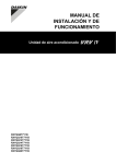
For all the models a piping diagram and outlook drawing are
available. Depending on the model type some components in the
main component list may not be existing in the unit.
Opening the unit
To gain access to the unit, front plates need to be opened as follows:
RXYQQ8~12
Main components (see figure 1, figure 2, figure 3, figure 4)
RXYQQ14~20
14x
1
2
3
4
5
6
7
8
9
10
11
12
13
14
15
16
17
18
14x
Once the front plates open, the electrical component box can be
accessed by removing the electrical component box cover as follows.
RXYQQ8~12
Main components in the unit
RXYQQ14~20
5.2.1.
Compressor (M1C)
Compressor (M2C)
Heat exchanger
Fan
Fan motor (M1F, M2F)
Accumulator
Expansion valve, main (Y1E)
Expansion valve, subcool heat exchanger (Y2E)
Subcool heat exchanger
Oil separator
Solenoid valve, oil accumulator (Y2S)
Solenoid valve, oil1 (Y3S)
Solenoid valve, oil2 (Y4S)
4-way valve, main (Y1S)
Electrical component box
Service port, refrigerant charge
Stop valve, liquid
Stop valve, gas
RXYQQ* (8~12 HP)
Piping diagram
See figure 1.
Outlook drawing
See figure 3.
6x
2x
5.2.2.
RXYQQ* (14~20 HP)
Piping diagram
See figure 2.
For service purposes, the push buttons on the main PCB need to be
accessed. To access these push buttons, the electrical component
box cover does not need to be opened. See "13. Making field
settings" on page 28.
Outlook drawing
See figure 4.
DANGER: Electrical shock
See "2. General safety precautions" on page 2.
DANGER: Do not touch piping and internal parts.
See "2. General safety precautions" on page 2.
Installation and operation manual
6
RXYQQ8~20T7Y1B
VRV IV System Air Conditioner
4P345099-1 – 2013.04
5.3.
Main components in the electrical component box
CAUTION
Appliance not accessible to the general public, install it in a
secured area, protected from easy access.
RXYQQ8~12
This appliance is intended to be used by expert or trained
users in shops, in light industry and on farms, or for
commercial use by lay persons.
1
3
6.1.
General precautions on installation
Select an installation site that meets the following requirements:
The foundation must be strong enough to support the weight of
the unit.
The floor is flat to prevent vibrations and noise generation and to
have sufficient stability.
2
4
The space around the unit is adequate for maintenance and
servicing (refer to "7.2. Service space" on page 9).
The space around the unit allows for sufficient air circulation.
There is no danger of fire due to leakage of inflammable gas.
The equipment is not intended for use in a potentially explosive
atmosphere.
Select the location of the unit in such a way that the sound
generated by the unit does not disturb anyone, and the location
is selected according the applicable legislation.
All piping lengths and distances have been taken into
consideration (refer to "9.5. System piping (length) limitations"
on page 13).
Take care that in the event of a water leak, water cannot cause
any damage to the installation space and surroundings.
When installing the unit in a small room, take measures in order
to keep the refrigerant concentration from exceeding allowable
safety limits in the event of a refrigerant leak, refer to
"18. Caution for refrigerant leaks" on page 47.
RXYQQ14~20
CAUTION
4
2 3 1
1 Main PCB.
2 Terminal block X1M: main terminal block which allows easy
connection of field wiring for power supply.
3 Terminal X1M on main PCB: terminal block for
transmission wiring.
4 Cable tie mountings: the cable tie mountings allow to fix
the field wiring with cable ties to the electrical component
box to ensure strain relief.
INFORMATION
For more details refer to the wiring diagram of the units.
The wiring diagram is located on the inside of the electrical
component box.
6.
Selecting an installation location
Excessive refrigerant concentrations in a closed room can
lead to oxygen deficiency.
NOTICE
The equipment described in this manual may cause
electronic noise generated from radio-frequency energy.
The equipment complies to specifications that are
designed to provide reasonable protection against such
interference. However, there is no guarantee that
interference will not occur in a particular installation.
It is therefore recommended to install the equipment and
electric wires keeping proper distances away from stereo
equipment, personal computers, etc.
3
2
5
(mm)
2
WARNING
4
Be sure to provide for adequate measures in order to
prevent that the unit is used as a shelter by small animals.
Small animals making contact with electrical parts can
cause malfunctions, smoke or fire. Please instruct the
customer to keep the area around the unit clean and clear.
This is a class A product. In a domestic environment this
product may cause radio interference in which case the
user may be required to take adequate measures.
3
4
6
1
1
2
3
4
5
6
Personal computer or radio
Fuse
Earth leakage protector
User interface
Indoor unit
Outdoor unit
In places with weak reception, keep distances of 3 m or more to
avoid electromagnetic disturbance of other equipment and use
conduit tubes for power and transmission lines.
RXYQQ8~20T7Y1B
VRV IV System Air Conditioner
4P345099-1 – 2013.04
Installation and operation manual
7
6.2.
The refrigerant R410A itself is nontoxic, non-flammable and is
safe. If the refrigerant should leak however, its concentration
may exceed the allowable limit depending on room size. Due to
this, it could be necessary to take measures against leakage.
Refer to "18. Caution for refrigerant leaks" on page 47.
Do not install in the following locations:
- Locations where sulphurous acids and other corrosive gases
may be present in the atmosphere. Copper piping and
soldered joints may corrode, causing refrigerant to leak.
- Locations where a mineral oil mist, spray or vapour may be
present in the atmosphere. Plastic parts may deteriorate and
fall off or cause water leakage.
- Locations where equipment that produces electromagnetic
waves is found. The electromagnetic waves may cause the
control system to malfunction, preventing normal operation.
- Locations where flammable gases may leak, where thinner,
gasoline and other volatile substances are handled, or where
carbon dust and other incendiary substances are found in the
atmosphere. Leaked gas may accumulate around the unit,
causing an explosion.
6.3.
Selecting a location in cold climates
NOTICE
When operating the unit in a low outdoor ambient
temperature, be sure to follow the instructions described
below.
To prevent exposure to wind and snow, install a baffle plate on the air
side of the outdoor unit:
1
When installing, take strong winds, typhoons or earthquakes into
account, improper installation may result in the unit turning over.
Weather related precautions
Select a place where the rain can be avoided as much as
possible.
Be sure that the air inlet of the unit is not positioned towards the
main wind direction. Frontal wind will disturb the operation of the
unit. If necessary, use a screen to block the wind.
Ensure that water cannot cause any damage to the location by
adding water drains to the foundation and prevent water traps in
the construction.
Do not install the unit in areas where the air contains high levels
of salt such as that near the ocean.
1 Baffle plate
In heavy snowfall areas it is very important to select an installation
site where the snow will not affect the unit. If lateral snowfall is
possible, make sure that the heat exchanger coil is not affected by
the snow (if necessary construct a lateral canopy). Install the unit
high enough from the ground to prevent burying in snow.
1
2
1 Construct a large canopy.
2 Construct a pedestal.
NOTICE
When operating the unit in a low outdoor ambient
temperature with high humidity conditions, make sure to
take precautions to keep the drainholes of the unit free by
using proper equipment. For more information contact your
local dealer.
Installation and operation manual
8
RXYQQ8~20T7Y1B
VRV IV System Air Conditioner
4P345099-1 – 2013.04
7.
Dimensions and service space
7.1.
Service space
The space around the unit is adequate for servicing and the minimum
space for air inlet and air outlet is available (refer to the figure below
and choose one of the possibilities).
Dimensions of outdoor unit
RXYQQ8~12
7.2.
766
b
b
729
c
aa
e
aa
d
c
e
d
4-15x22.5
b
b
c
e
1685
f
d
aa
aa
515
276
259
179
131
122
d
76
137
76
(mm)
b
b
97
765
c
e
107
272
328
373
c
e
f
930
aa
RXYQQ14~20
1076
729
d
765
276
259
179
131 122
515
76
76
137
(mm)
97
107
272
328
373
A+B
a≥50 mm
b≥100 mm
c≥50 mm
d≥500 mm
a≥200 mm
b≥300 mm
a≥10 mm
b≥300 mm
c≥10 mm
d≥500 mm
e≥20 mm
a≥50 mm
b≥100 mm
c≥50 mm
d≥500 mm
e≥100 mm
a≥200 mm
b≥300 mm
a≥10 mm
b≥300 mm
c≥10 mm
d≥500 mm
e≥20 mm
f≥600 mm
a≥50 mm
b≥100 mm
c≥50 mm
d≥500 mm
e≥100 mm
f≥500 mm
a≥10 mm
b≥300 mm
c≥10 mm
d≥500 mm
e≥20 mm
a≥50 mm
b≥100 mm
c≥50 mm
d≥500 mm
e≥100 mm
a≥10 mm
b≥500 mm
c≥10 mm
d≥500 mm
e≥20 mm
f≥900 mm
a≥50 mm
b≥500 mm
c≥50 mm
d≥500 mm
e≥100 mm
f≥600 mm
1685
4-15x22.5
A+B+C+D
a≥10 mm
b≥300 mm
c≥10 mm
d≥500 mm
1240
e≥400 mm
F
h1
500
1500
h2
(mm)
ABCD Sides along the installation site with obstacles
F Front side
Suction side
RXYQQ8~20T7Y1B
VRV IV System Air Conditioner
4P345099-1 – 2013.04
In case of an installation site where sides A+B+C+D have
obstacles, the wall heights of sides A+C have no impact on
service space dimensions. Refer to the figure above for impact
of wall heights of sides B+D on service space dimensions.
In case of an installation site where only the sides A+B have
obstacles, the wall heights have no influence on any indicated
service space dimensions.
Installation and operation manual
9
The installation space required on these drawings are for full
load heating operation without considering possible ice
accumulation.
If the location of the installation is in a cold climate, then all
dimensions above should be >500 mm to avoid accumulation of
ice in between the outdoor units.
INFORMATION
8.3.
Unpacking
CAUTION
To avoid injury, do not touch the air inlet or aluminium fins
of the unit.
Relief the unit from its packing material:
The service space dimensions in above figure are based
on cooling operation at 35°C ambient temperature
(standard conditions).
RXYQQ8~12
RXYQQ14~20
INFORMATION
Further specifications can be found in the technical
engineering data.
8.
8.1.
Inspecting, handling and unpacking
the unit
Inspection
At delivery, the unit must be checked and any damage must be
reported immediately to the carrier's claims agent.
8.2.
1
Take care not to damage the unit when removing the shrink foil with a
cutter.
Handling
When handling the unit, take into account the following:
WARNING
Fragile, handle the unit with care.
Tear apart and throw away plastic packaging bags so that
children will not play with them. Children playing with
plastic bags face danger of death by suffocation.
Keep the unit upright in order to avoid compressor
damage.
2
3
Choose on beforehand the path along which the unit is to be
brought in.
1
Remove the 4 bolts fixing the unit to its pallet.
2
Make sure that all accessories as mentioned in
"4.1. Accessories supplied with this unit" on page 4 are available
in the unit.
Bring the unit as close as possible to its final installation position
in its original package to prevent damage during transport.
2
4
2
1
8.4.
4
Installing the unit
Make sure the unit is installed level on a sufficiently strong base to
prevent vibration and noise.
4
NOTICE
3
When the installation height of the unit needs to be
increased, do not use stands to only support the corners.
3
1
2
3
4
4
Packaging material
Belt sling
Opening
Protector
Lift the unit preferably with a crane and 2 belts of at least 8 m
long as shown in the figure above.
Always use protectors to prevent belt damage and pay attention
to the position of the unit's centre of gravity.
A forklift can only be used for transport as long as the unit remains on
its pallet as shown above.
Installation and operation manual
10
P
P
X Not allowed
O Allowed
The height of the foundation must at least be 150 mm from the
floor.
In heavy snowfall areas, this height should be increased,
depending on the installation place and condition.
The unit must be installed on a solid longitudinal foundation
(steel beam frame or concrete) and make sure the base under
the unit is larger than the grey marked area.
NOTICE
Use a belt sling of ≤20 mm wide that adequately bears the
weight of the unit.
P
P
RXYQQ8~20T7Y1B
VRV IV System Air Conditioner
4P345099-1 – 2013.04
4
3
6 7
1 2
9.
5
AB
Refrigerant pipe size and allowable
pipe length
AA
General information
NOTICE
929
729
9.1.
The refrigerant R410A requires strict cautions for keeping
the system clean, dry and tight.
Clean and dry: foreign materials (including mineral
oils or moisture) should be prevented from getting
mixed into the system.
Tight: R410A does not contain any chlorine, does not
destroy the ozone layer, and does not reduce earth's
protection against harmful ultraviolet radiation. R410A
can contribute slightly to the greenhouse effect if it is
released. Therefore we should take special attention
to check the tightness of the installation.
(mm)
1
2
3
4
5
6
7
Hole for foundation bolt
Inner dimension of the base
Distance between foundation bolt holes
Depth of unit
Outer dimension of the base
Longitudinal foundation dimension
Distance between foundation bolt holes
8~12 HP
14~20 HP
AA
766
1076
AB
992
1302
Fasten the unit in place using four
foundation bolts M12. It is best to screw in
the foundation bolts until their length
remains 20 mm above the foundation
surface.
When existing field piping is re-used, the design pressure
of the piping has to be 33 bar (3.3 MPa) or higher.
20 mm
NOTICE
INFORMATION
The RXYQQ unit will limit the pressure on the field piping
to 33 bar. Inside the outdoor unit, the design pressure is
40 bar.
NOTICE
Prepare a water drainage channel around the
foundation to drain waste water from around the unit.
During heating operation and when the outdoor
temperatures are negative, the drained water from the
outdoor unit will freeze up. If the water drainage is not
taken care of, the area around the unit might be very
slippery.
9.2.
NOTICE
Piping and other pressure containing parts shall comply
with the applicable legislation and shall be suitable for
refrigerant. Use phosphoric acid deoxidised seamless
copper for refrigerant.
When installed in a corrosive
environment, use a nut with
plastic washer (1) to protect the
nut tightening part from rust.
NOTICE
1
8.5.
Method for removing transportation stay (only
Installation shall be done by a licensed installer, the choice
of materials and installation shall conform completely with
the applicable national and international codes.
for
RXYQQ14~20)
The yellow transportation stay installed over the compressor leg for
protecting the unit during transport must be removed. Proceed as
shown in the figure and procedure below.
1
Slightly loosen the fixing nut (A).
2
Remove the transportation stay (B) as shown in the figure below.
3
Tighten the fixing nut (A) again (12.3 N•m).
2
3 (12.3 N·m)
1
Selection of piping material
In Europe, EN 378 is the applicable standard that shall be
used.
Foreign materials inside pipes (including oils for fabrication)
must be ≤30 mg/10 m.
Temper grade: use piping with temper grade in function of the
pipe diameter as listed in table below.
Pipe Ø (mm)
Temper grade of piping material
≤15.9
O (annealed)
≥19.1
1/2H (half hard)
A
B
NOTICE
If the unit is operated with the transportation stay attached,
abnormal vibration or noise may be generated.
RXYQQ8~20T7Y1B
VRV IV System Air Conditioner
4P345099-1 – 2013.04
Installation and operation manual
11
9.3.
Selection of piping size
9.3.3.
Determine the proper size referring to following tables and reference
figure (only for indication).
Piping between refrigerant branch kit and indoor unit: E
Pipe size for direct connection to indoor unit must be the same as the
connection size of the indoor unit.
Piping outer diameter size
(mm)
Indoor unit capacity index
A
a
B
C y
x
B
B
D
b
Gas pipe
Liquid pipe
15, 20, 25, 32, 40, 50
12.7
6.4
63, 80, 100, 125
15.9
200
19.1
250
22.2
c
E
1
2
3
When the equivalent pipe length between outdoor and indoor
units is 90 m or more, the size of the main pipes (both gas side
and liquid side) must be increased. Depending on the length of
the piping, the capacity may drop, but even in such a case it is
possible to increase the size of the main pipes.
4
2
1
3
1~4 VRV DX indoor unit
a,b,c Indoor branch kit
x,y Outdoor multi connection kit
9.3.1.
1
2
3
4
5
Choose from the following table in accordance with the outdoor unit
total capacity type, connected downstream.
8
Liquid pipe
9.5
22.2
12~16
12.7
28.6
18~22
15.9
24
34.9
26~34
36~42
19.1
41.3
Choose from the following table in accordance with the indoor unit
total capacity type, connected downstream. Do not let the connection
piping exceed the refrigerant piping size chosen by the general
system model name.
Piping outer diameter size (mm)
Gas pipe
<150
15.9
150≤x<200
19.1
200≤x<290
22.2
290≤x<420
420≤x<640
28.6
HP Class
Liquid pipe
9.5
Gas side (mm)
8
19.1 → 22.2
10
22.2 → 25.4(a)
Liquid size (mm)
9.5 → 12.7
28.6(b)
12+14
12.7 → 15.9
16
28.6 → 31.8(a)
18~22
28.6 → 31.8(a)
15.9 → 19.1
34.9(b)
15.9 → 19.1
24
Piping between refrigerant branch kits: D
Indoor unit capacity
index
Outdoor unit
Main pipes
Increase
First refrigerant branch kit
Indoor unit
Size up
19.1
10
9.3.2.
Piping outer diameter size (mm)
Gas pipe
5
4
Piping between outdoor unit and (first) refrigerant
branch kit: A, B, C
Outdoor unit capacity
type (HP)
9.5
26~34
34.9 → 38.1(a)
36~42
41.3(b)
19.1 → 22.2
(a) If size is NOT available, increase is NOT allowed.
(b) Increase is NOT allowed.
The pipe thickness of the refrigerant piping shall comply with the
applicable legislation. The minimal pipe thickness for R410A
piping must be in accordance with the table below.
Pipe Ø (mm)
Minimal thickness t (mm)
6.4
0.4
9.5
0.5
12.7
12.7
0.7
15.9
15.9
0.9
640≤x<920
34.9
19.1
19.1
0.6(a)
>920
41.3
19.1
22.2
0.6
28.6
0.8
31.8
0.9
34.9
1.0
Example:
Downstream capacity for E=capacity index of unit 1
Downstream capacity for D=capacity index of unit 1+capacity index
of unit 2
38.1
41.3
1.1
(a) If annealed temper grade is 1.
The refrigerant pipes and branches must meet the condition of
design pressure 33 bar (3.3 MPa). If it is NOT possible to
confirm this, use the refrigerant branch as mentioned in this
chapter.
Confirm that the (pipe) thickness may NOT be less than the
required minimum thickness.
Installation and operation manual
12
RXYQQ8~20T7Y1B
VRV IV System Air Conditioner
4P345099-1 – 2013.04
In case the required pipe sizes (inch sizes) are not available, it is
also allowed to use other diameters (mm sizes), taken the
following into account:
- Select the pipe size nearest to the required size.
- Use the suitable adapters for the change-over from inch
to mm pipes (field supply).
In this case, the additional refrigerant calculation has to be
adjusted as mentioned in "14. Charging refrigerant" on page 30.
9.5.
System piping (length) limitations
9.5.1.
Piping length restrictions
Make sure to perform the piping installation within the range of the
maximum allowable pipe length, allowable level difference and
allowable length after branching as indicated below.
Definitions
Actual piping length: pipe length between outdoor(1) and indoor units.
9.4.
Selection of refrigerant branch kits
Refrigerant refnets
For piping example, refer to "9.3. Selection of piping size" on
page 12.
When using refnet joints at the first branch counted from the
outdoor unit side, choose from the following table in accordance
with the capacity of the outdoor unit (example: refnet joint a).
Outdoor unit capacity type (HP)
KHRQ22M29T9
12-22
KHRQ22M64T
24-42
KHRQ22M75T
Difference in height between outdoor and indoor units: H1.
Difference in height between indoor and indoor units: H2.
Difference in height between outdoor and outdoor units: H3.
For refnets joints other than the first branch (example refnet joint
b), select the proper branch kit model based on the total capacity
index of all indoor units connected after the refrigerant branch.
Indoor unit capacity index
2 pipes
<200
KHRQ22M20T
200≤x<290
KHRQ22M29T9
290≤x<640
KHRQ22M64T
≥640
KHRQ22M75T
Total piping length: total piping length from the outdoor(1) to all indoor
units.
2 pipes
8-10
Equivalent piping length(2): pipe length between outdoor(1) and
indoor units.
Concerning refnet headers, choose from the following table in
accordance with the total capacity of all the indoor units
connected below the refnet header.
Indoor unit capacity index
2 pipes
<200
KHRQ22M29H
200≤x<290
KHRQ22M29H
290≤x<640
KHRQ22M64H(a)
≥640
KHRQ22M75H
(a) If the pipe size above the refnet header is Ø34.9 or more, KHRQ22M75H is
required.
INFORMATION
Maximum 8 branches can be connected to a header.
How to choose an outdoor multi connection piping kit (needed if
the outdoor unit capacity type is 22 HP or more). Choose from
the following table in accordance with the number of outdoor
units.
Number of outdoor units
Branch kit name
2
BHFQ22P1007
3
BHFQ22P1517
NOTICE
Refrigerant branch kits can only be used with R410A.
(1)
(2)
RXYQQ8~20T7Y1B
VRV IV System Air Conditioner
4P345099-1 – 2013.04
If the system capacity is >20HP, re-read "the first outdoor branch as seen
from the indoor unit".
Assume equivalent piping length of refnet joint=0.5 m and refnet
header=1 m (for calculation purposes of equivalent piping length, not for
refrigerant charge calculations).
Installation and operation manual
13
9.5.2.
System containing VRV DX indoor units
System setup
Branch with refnet joint and refnet
header
Branch with refnet joint
Branch with refnet header
Single outdoor
i
a
b
a
A
c
d
B
h
C
i
1
e
D
j
2
E
k
3
g
f
F
l
4
G
m
5
p
n
6
A
c
7
H2
d
1
8
k
j
e
2
a
B
b
H1 H1
g
f
3
4
7
8
H2
h
5
H1
b
1
6
d
c
2
e
3
4
Example 1.2
Example 1.1
f
g
5
h
6
i
7
H2
Example 1.3
8
Multi outdoor
H3
H3
Indoor unit
a
Refnet joint
s
r
u
b
A
Refnet header
c
B
h
d
C
i
1
r
u
t
j
2
e
D
k
3
f
E
g
F
l
4
m
5
Example 2.1
Outdoor multi
connection piping
kit
A
7
c
8
B
b
p
n
6
a
H1
G
H3
t
s
d
1
j
e
2
f
3
g
4
h
5
H2
7
8
r
u
H1
k
b
6
a
c
1
t
s
H1
d
2
e
3
f
4
g
5
6
h
i
7
8
Example 3: with standard multi layout
r
s
t
u
Maximum allowable length
Between outdoor and indoor units
Actual piping length
120 m
Example 1.2
unit 6: a+b+h≤120 m
unit 8: a+i+k≤120 m
Example 1.1
unit 8: a+b+c+d+e+f+g+p≤120 m
Example 2.1
unit 8: a+b+c+d+e+f+g+p≤120 m
Example 1.3
unit 8: a+i≤120 m
Equivalent length(2)
150 m
—
—
—
Total piping length
300 m
Example 1.1
a+b+c+d+e+f+g+h+i+j+k+l+m+n+p≤300 m
—
—
Example 2.1
a+b+c+d+e+f+g+h+i+j+k+l+m+n+p≤300 m
Between outdoor branch and outdoor unit (only in case >20 HP)
Maximum allowable length after branch
Actual piping length
10 m
Example 3
r, s, t≤10 m; u≤5 m
The pipe length from the first refrigerant branch kit to the indoor unit
≤40 m.
Equivalent length
13 m
—
Example 1.1: unit 8: b+c+d+e+f+g+p≤40 m
Maximum allowable height difference
Example 1.2: unit 6: b+h≤40 m, unit 8: i+k≤40 m
H1
≤50 m (40 m) (if outdoor is located below indoor units)
Example 1.3: unit 8: i≤40 m
H2
≤15 m
H3
≤5 m
However, extension is possible if all below conditions are met. In this
case limitation can be extended up to 90 m.
1
2
3
b
a
A
c
B
h
1
d
C
i
2
e
D
j
3
f
E
k
4
g
F
l
G
m
5
p H1
n
6
7
H2
8
1 Outdoor units
2 Refnet joints (A~G)
3 Indoor unit (1~8)
Installation and operation manual
14
a.
The piping length between all indoor to the nearest branch kit is
≤40 m.
Example: h, I, j … p≤40 m
b.
It is necessary to increase the pipe size of the gas and liquid
piping if the pipe length between the first and the final branch kit
is over 40 m.
If the increased pipe size is larger than the pipe size of the main
pipe, then the pipe size of the main pipe has to be increased as
well.
RXYQQ8~20T7Y1B
VRV IV System Air Conditioner
4P345099-1 – 2013.04
Increase the pipe size as follows:
9.5 → 12.7; 12.7 → 15.9; 15.9 → 19.1; 19.1 → 22.2; 22.2 →
25.4(3); 28.6 → 31.8(3); 34.9 → 38.1(3)
Example: unit 8: b+c+d+e+f+g+p≤90 m and b+c+d+e+f+g
>40 m; increase the pipe size of b, c, d, e, f, g.
c.
d.
When the piping size is increased (step b), the piping length has
to be counted as double (except for the main pipe and the pipes
that are not increased in pipe size).
The total piping length has to be within limitations (see table
above).
Example:
a+b*2+c*2+d*2+e*2+f*2+g*2+h+i+j+k+l+m+n+p≤300 m.
The piping length difference between the nearest indoor from
first branch to the outdoor unit and farthest indoor to the outdoor
unit is ≤40 m.
Example: The farthest indoor unit 8. The nearest indoor unit 1 →
(a+b+c+d+e+f+g+p)–(a+h)≤40 m.
9.6.
Prohibited patterns: change to pattern 1 or 2.
1
1
2
2
1 To indoor unit
2 Piping between outdoor units
To avoid the risk of oil retention to the outmost outdoor unit,
always connect the stop valve and the piping between outdoor
units as shown in the 4 correct possibilities of the figure below.
Prohibited patterns: change to pattern 1 or 2.
Multi system piping installation
1
Front connection
Remove the front plate knock out holes to connect (see figure
below).
1
2
2
2
2
2
2
1 To indoor unit
2 Oil collects to the outmost outdoor unit
Change to configuration as in figures below
1
Bottom connection
Remove the knock out holes on the bottom frame and route the
piping under the bottom frame (see figure below).
1
2
1
2
2
1 To indoor unit
2 Oil collects to the outmost outdoor unit when the system
stops
PP
Correct configuration
To connect the piping between outdoor units, an optional multi
connection piping kit BHFQ22P1007/1517 is always required.
When installing the piping, follow the instructions in the
installation manual that comes with the kit.
Only proceed with piping work after considering the limitations
on installing listed here and in the chapter "10.2. Connecting the
refrigerant piping" on page 17 always referring to the installation
manual delivered with the kit.
9.6.2.
1
1
1
1 To indoor unit
If the piping length between the outdoor units exceeds 2 m,
create a rise of 200 mm or more in the gas line within a length of
2 m from the kit.
If ≤2 m
Possible installation patterns and configurations
2
The piping between the outdoor units must be routed level or
slightly upward to avoid the risk of oil retention into the piping.
Pattern 1
Pattern 2
1
2
1
2
1
2
1
2
P
1 To indoor unit
2 Piping between outdoor units
If >2 m
1 To indoor unit
2 Piping between outdoor units
(3)
1
!P
!P
PP
Precautions when connecting piping between outdoor
units (multiple outdoor unit system)
PP
9.6.1.
1
P
P
1 To indoor unit
2 Piping between outdoor units
If available on the site. Otherwise it cannot be increased.
RXYQQ8~20T7Y1B
VRV IV System Air Conditioner
4P345099-1 – 2013.04
Installation and operation manual
15
Example: passing piping out through the front.
NOTICE
There are restrictions on the refrigerant pipe connection
order between outdoor units during installation in case of a
multiple outdoor unit system. Install according to following
restrictions. The capacities of outdoor units A, B and C
must fulfill the following restriction conditions: A≥B≥C.
A
1 2
B
C
1
Use clean pipes only.
Hold the pipe end downwards when removing burrs.
Cover the pipe end when inserting it through a wall so that no
dust or dirt enters the pipe.
3
NOTICE
1 To indoor units
2 Outdoor unit multi connecting piping kit (first branch)
3 Outdoor unit multi connecting piping kit (second branch)
10. Precautions on refrigerant piping
Do not allow anything other than the designated refrigerant to
get mixed into the refrigerant cycle, such as air, nitrogen, etc. If
any refrigerant gas leaks while working on the unit, ventilate the
room thoroughly right away.
When the design pressure for the existing field piping (gas and
liquid piping) is at least 33 bar (3.3 MPa), then it is possible to
use the existing piping (please read "9. Refrigerant pipe size and
allowable pipe length" on page 11). Check also if the existing
piping (including branch piping) is compatible with the unit in
terms of materials and thickness and if the pipes and branch
piping are not corroded.
If the existing field piping does not comply with the conditions
above, replace the existing field piping with field piping which
meets the specified conditions.
Check if there was no compressor malfunction or similar issues
that could contribute to piping problems in the past. If there
where such problems, check that the appropriate repairs where
made, and if not, implement such repairs.
Use R410A only when adding refrigerant
Installation tools:
Make sure to use installation tools (gauge manifold, charge
hose, etc.) that are exclusively used for R410A installations to
withstand the pressure and to prevent foreign materials (e.g.,
mineral oils and moisture) from mixing into the system.
Vacuum pump:
- Use a 2-stage vacuum pump with a non-return valve.
- Make sure the pump oil does not flow oppositely into the
system while the pump is not working.
- Use a vacuum pump which can evacuate to –100.7 kPa
(5 Torr, –755 mm Hg).
1 Close the areas marked with "
".
(When the piping is routed from the
front panel.)
After all the piping has been connected, make sure there is
no gas leak. Use nitrogen to perform a gas leak detection.
10.1. Caution for brazing
Make sure to blow through with nitrogen when brazing. Blowing
through with nitrogen prevents the creation of large quantities of
oxidized film on the inside of the piping. An oxidized film
adversely affects valves and compressors in the refrigerating
system and prevents proper operation.
The nitrogen pressure should be set to 0.02 MPa (i.e., just
enough so it can be felt on the skin) with a pressure-reducing
valve.
1
2
3
6
1
2
3
4
5
6
4
5
6
Refrigerant piping
Part to be brazed
Taping
Hands valve
Pressure-reducing valve
Nitrogen
Do not use anti-oxidants when brazing the pipe joints. Residue can
clog pipes and break equipment:
Do not use flux when brazing copper-to-copper refrigerant
piping. Use phosphor copper brazing filler alloy (BCuP) which
does not require flux.
Flux has an extremely harmful influence on refrigerant piping
systems. For instance, if chlorine based flux is used, it will cause
pipe corrosion or, in particular, if the flux contains fluorine, it will
deteriorate the refrigerant oil.
Protection against contamination when installing pipes
Take measures to prevent foreign materials like moisture and
contamination from mixing into the system.
Installation period
Protection method
More than a month
Pinch the pipe
Less than a month
Regardless of the period
Pinch or tape the pipe
Block all gaps in the holes for passing out piping and wiring using
sealing material (field supply) (the capacity of the unit will drop and
small animals may enter the machine).
Installation and operation manual
16
RXYQQ8~20T7Y1B
VRV IV System Air Conditioner
4P345099-1 – 2013.04
10.2. Connecting the refrigerant piping
2
Connect the vacuuming/recovery unit to service ports of all stop
valves.
6
NOTICE
Installation shall be done by an installer, the choice of
materials and installation shall comply with the applicable
legislation. In Europe, EN 378 is the applicable standard
that shall be used.
A
1
4
2
1 Left-side connection
2 Front connection
3 Right-side connection
3
2
For side connections, the knockout hole on the bottom plate
should be removed:
1 Large knockout hole
2 Drill
3 Points for drilling
2
3
11
3
1
2
3
4
5
6
7
8
9
A
B
C
10
11
12
13
14
Installation of refrigerant piping is possible as front connection or side
connection (when taken out from the bottom) as shown in the figure
below.
1
8
12
C
10.2.1. Decide front or side (bottom) connection
10
B
Ensure that the field piping and connections are not
subjected to stress.
1
9
7
13
14
5
Gauge manifold
Nitrogen
Measuring instrument
Refrigerant R410A tank (siphon system)
Vacuum pump
Charge hose
Refrigerant charge port
Gas pipe stop valve
Liquid pipe stop valve
Valve A
Valve B
Valve C
Outdoor unit
To indoor unit
Stop valve
Field piping
Gas flow
Recover gas and oil from the pinched piping by using a recovery
unit.
CAUTION
3
Do not vent gases into the atmosphere.
4
When all gas and oil is recovered from the pinched piping,
disconnect the charge hose and close the service ports.
5
In case the pinched piping lower part looks like detail A in the
figure below, follow instructions as per procedure steps 7+8.
In case the pinched piping lower part looks like detail B in the
figure below, follow instructions as per procedure steps 6+7+8.
NOTICE
Precautions when knocking out knockout holes:
Be sure to avoid damaging the casing.
After knocking out the knockout holes, we recommend
you remove the burrs and paint the edges and areas
around the edges using repair paint to prevent rusting.
When passing electrical wiring through the knockout
holes, wrap the wiring with protective tape to prevent
damage as shown above.
3
1
2
3
4
2
Pinched piping
Stop valve
Service port
Point of melting the brazing
metal; cut pipe off just above
this brazing or marking point
10.2.2. Remove the pinched pipes
WARNING
Any gas or oil remaining inside the stop valve may blow off
the pinched piping.
Failure to observe the instructions in procedure below
properly may result in property damage or personal injury,
which may be serious depending on the circumstances.
Use the following procedure to remove the pinched piping:
1
Remove the valve cover and make sure that the stop valves are
fully closed.
A B
1
4
6
For stop valves, cut off the lower part of the smaller pinched
piping with an appropriate tool (e.g., pipe cutter, a pair of
nippers, …). Let the remaining oil drip out in case the recovery
was not complete.
1 Service port and service
port cover
2 Stop valve
3 Field piping connection
4 Stop valve cover
1
2
3
4
Wait until all oil is dripped out.
RXYQQ8~20T7Y1B
VRV IV System Air Conditioner
4P345099-1 – 2013.04
Installation and operation manual
17
7
Cut the pinched piping off with a pipe cutter just above the
brazing point or marking if there is no brazing point.
10.2.4. Branching the refrigerant piping
WARNING
For installation of the refrigerant branching kit, refer to the
installation manual delivered with the kit.
Never remove the pinched piping by
brazing.
Any gas or oil remaining inside the stop
valve may blow off the pinched piping.
8
±30°
Failure to observe the instructions in
procedure below properly may result in
property damage or personal injury, which may be serious
depending on the circumstances.
A
1
Wait until all oil is dripped out before continuing with the
connection of the field piping in case the recovery was not
complete.
1
B
10.2.3. Connecting refrigerant piping to the outdoor unit
INFORMATION
All local inter unit piping are field supplied except the
accessory pipes.
1 Horizontal surface
1 Mount the refnet joint so that it branches either horizontally or
vertically.
2 Mount the refnet header so that it branches horizontally.
NOTICE
Precautions when connecting field piping. Add brazing
material as shown in the figure.
Installation of the multi connection piping kit.
max
15 A
!
1
1
2
1
1
2
1
B
1
NOTICE
Be sure to use the supplied accessory pipes when
carrying out piping work in the field.
Be sure that the field installed piping does not touch
other pipes, the bottom panel or side panel. Especially
for the bottom and side connection, be sure to protect
the piping with suitable insulation, to prevent it from
coming into contact with the casing.
Connection from the stop valves to the field piping can be done by
using accessory pipes supplied as accessory.
>12
0
>50 mm
0m
m
NOTICE
Make sure that the onsite piping does not come in contact
with other piping, the bottom frame or side panels of the
unit.
The connections to the branch kits are the responsibility of the
installer (field piping).
1 Install the joints horizontally, so that the caution label (1)
attached to the joint comes to the top.
- Do not tilt the joint more than 15° (see view A).
- Do not install the joint vertically (see view B).
2 Make sure that the total length of the piping connected to the
joint is absolute straight for more than 500 mm. Only if a
straight field piping of more than 120 mm is connected, more
than 500 mm of straight section can be ensured.
3 Improper installation may lead to malfunction of the outdoor
unit.
Installation and operation manual
18
RXYQQ8~20T7Y1B
VRV IV System Air Conditioner
4P345099-1 – 2013.04
10.3. Guidelines for handling stop valve
10.3.1. Cautions on handling the stop valve
Make sure to keep both stop valves open during operation.
The figure below shows the name of each part required in
handling the stop valve.
The stop valve is factory closed.
10.3.3. Cautions on handling the stop valve cover
The stop valve cover is sealed where indicated by the arrow.
Take care not to damage it.
After handling the stop valve, make sure to tighten the stop
valve cover securely. For the tightening torque, refer to the table
below.
Check for refrigerant leaks after tightening the stop valve cover.
1 Service port and service
port cover
2 Stop valve
3 Field piping connection
4 Stop valve cover
1
2
3
10.3.4. Cautions on handling the service port
4
1
5
2
4
1
2
3
4
5
Service port
Cap
Hexagon hole
Shaft
Seal
3
Always use a charge hose equipped with a valve depressor pin,
since the service port is a Schrader type valve.
After handling the service port, make sure to tighten the service
port cover securely. For the tightening torque, refer to the table
below.
Check for refrigerant leaks after tightening the service port
cover.
10.3.5. Tightening torques
10.3.2. How to use the stop valve
Tightening torque N•m (turn clockwise to close)
Opening the stop valve
Shaft
1
Remove the valve cover.
2
Insert a hexagon wrench into the stop valve and turn the stop
valve counterclockwise.
3
When the stop valve cannot be turned any further, stop turning.
The valve is now open.
To fully open the Ø19.1 or Ø25.4 gas line stop valve, turn the
hexagonal wrench until a torque between 27 and 33 N•m is achieved.
Inadequate torque may cause leakage of refrigerant and breakage of
the stop valve cap.
Stop valve
size (mm)
Valve body
Ø9.5
5.4~6.6
Ø12.7
8.1~9.9
Ø15.9
13.5~16.5
6 mm
23.0~27.0
27.0~33.0
8 mm
22.5~27.5
Ø19.1
Ø25.4
Hexagonal
wrench
Cap (valve
lid)
Service port
13.5~16.5
4 mm
18.0~22.0
11.5~13.9
10.4. Leak test and vacuum drying
It is very important that all refrigerant piping work is done before the
units (outdoor or indoor) are powered on.
When the units are powered on, the expansion valves will initialize.
This means that they will close. Leak test and vacuum drying of field
piping and indoor units is impossible when this happens.
2
3
1
Therefore, there will be explained 2 methods for initial installation,
leak test and vacuum drying.
Refrigerant piping works are
finished?
4
No
Finish piping work
Yes
The indoor units and/or
outdoor unit were already
powered ON?
NOTICE
Pay attention that mentioned torque range is applicable for
opening Ø19.1 and Ø25.4 gas line stop valves only.
Yes
No
Use procedure
"10.4.2. Installation of
refrigerant piping, leak test,
vacuuming before electrical
installation is done (regular
installation method)" on
page 20.
Closing the stop valve
1
Remove the valve cover.
2
Insert a hexagon wrench into the stop valve and turn the stop
valve clockwise.
3
When the stop valve cannot be turned any further, stop turning.
The valve is now closed.
Use procedure
"10.4.3. Installation of
refrigerant piping, leak test,
vacuuming after electrical
installation is done on any
indoor or outdoor unit" on
page 20.
Closing direction
Liquid side
RXYQQ8~20T7Y1B
VRV IV System Air Conditioner
4P345099-1 – 2013.04
Gas side
Installation and operation manual
19
10.4.1. General guidelines
Use a 2-stage vacuum pump with a non-return valve which can
evacuate to a gauge pressure of –100.7 kPa (5 Torr absolute,
–755 mm Hg).
Connect the vacuum pump to the service port of all stop valves
to increase efficiency (refer to "10.4.4. Setup" on page 20).
10.4.4. Setup
6
1
NOTICE
Do not purge the air with refrigerants. Use a vacuum pump
to evacuate the installation.
When all piping work is complete, it is necessary to:
Check for any leakages in the refrigerant piping.
Perform vacuum drying to remove all moisture, air or nitrogen in
the refrigerant piping.
If there is a possibility of moisture being present in the refrigerant
piping (for example, rainwater may have entered the piping), carry
out the vacuum drying procedure below until all moisture has been
removed.
All piping inside the unit has been factory tested for leaks.
Only field installed refrigerant piping needs to be checked. Therefore,
make sure that all the outdoor unit stop valves are firmly closed
before performing leak test or vacuum drying.
5
C
See "10.4.4. Setup" on page 20 and "10.4. Leak test and vacuum
drying" on page 19.
Which valves?
Valve A
Close
Valve B
Open
Valve C
Open
Liquid side stop valve
Close
Gas side stop valve
Close
NOTICE
The connections to the indoor units and all indoor units
should also be leak and vacuum tested. Keep any possible
(field supplied) field piping valves open as well.
Refer to the indoor unit installation manual for more details.
Leak test and vacuum drying should be done before the
power supply is set to the unit. If not, see also the flow
chart earlier described in this chapter (see "10.4. Leak test
and vacuum drying" on page 19).
NOTICE
Make sure that all indoor units connected to the
outdoor unit are powered on.
Wait until the outdoor unit has finished the initialisation
to apply setting [2-21].
When all piping work is complete, it is necessary to:
State of valves
Performing the airtightness test and
vacuum drying (Valve A must always
be shut. Otherwise the refrigerant in
the unit will pour out.)
Apply outdoor unit setting [2-21]=1 (refer to "15.2. Monitoring function
and field settings" on page 37) before starting leak test and
vacuuming. This setting will open field expansion valves to guarantee
a R410A piping pathway.
Make sure that all (field supplied) field piping valves
are OPEN (not outdoor unit stop valves!) before you
start leak test and vacuuming.
11
12
13
14
15
State of the valves A, B, and C and
the stop valve
10.4.3. Installation of refrigerant piping, leak test, vacuuming
after electrical installation is done on any indoor or
outdoor unit
10
Pressure reducing valve
Nitrogen
Measuring instrument
Refrigerant R410A tank (siphon system)
Vacuum pump
Charge hose
Refrigerant charge port
Gas line stop valve
Liquid line stop valve
Outdoor unit
To indoor unit
Stop valve
Field piping
Gas flow
Stop valve service port
Valve A
Valve B
Valve C
NOTICE
Make sure that all (field supplied) field piping valves are
OPEN (not outdoor unit stop valves!) before you start leak
test and vacuuming.
10
B
3
1
2
3
4
5
6
7
8
9
10
11
12
13
14
15
A
B
C
10.4.2. Installation of refrigerant piping, leak test, vacuuming
before electrical installation is done (regular installation
method)
10
8
9
4
2
A 7
10.4.5. Leak test
The leak test must satisfy the specifications of EN 378-2:
1
Vacuum leak test:
1.1 Evacuate the system from the liquid and gas piping to
–100.7 kPa (5 Torr) for more than 2 hours.
Check for any leakages in the refrigerant piping.
1.2 Once reached, turn off the vacuum pump and check that the
pressure does not rise for at least 1 minute.
Perform vacuum drying to remove all moisture, air or nitrogen in
the refrigerant piping.
1.3 Should the pressure rise, the system may either contain
moisture (see vacuum drying below) or have leaks.
If there is a possibility of moisture being present in the refrigerant
piping (for example, rainwater may have entered the piping), first
carry out the vacuum drying procedure below until all moisture has
been removed.
All piping inside the unit has been factory tested for leaks.
Only field installed refrigerant piping needs to be checked. Therefore,
make sure that all the stop valves are firmly closed before performing
leak test or vacuum drying.
2
Pressure leak test:
2.1 Break the vacuum by pressurizing with nitrogen gas to a
minimum gauge pressure of 0.2 MPa (2 bar). Never set the
gauge pressure higher than the maximum operation pressure of
the system, i.e. 3.3 MPa (33 bar).
2.2 Test for leaks by applying a bubble test solution to all piping
connections.
2.3 Discharge all nitrogen gas.
See "10.4.4. Setup" on page 20 and "10.4. Leak test and vacuum
drying" on page 19.
Installation and operation manual
20
RXYQQ8~20T7Y1B
VRV IV System Air Conditioner
4P345099-1 – 2013.04
NOTICE
Make sure to use a recommended bubble test solution
from your wholesaler. Do not use soap water, which may
cause cracking of flare nuts (soap water may contain salt,
which absorbs moisture that will freeze when the piping
gets cold), and/or lead to corrosion of flared joints (soap
water may contain ammonia which causes a corrosive
effect between the brass flare nut and the copper flare.
If there is a possibility that condensation on the stop valve might
drip down into the indoor unit through gaps in the insulation and
piping because the outdoor unit is located higher than the indoor
unit, this must be prevented by sealing up the connections. See
below figure.
2
1
10.4.6. Vacuum drying
To remove all moisture from the system, proceed as follows:
1
Evacuate the system for at least 2 hours to a target vacuum of
–100.7 kPa.
2
Check that, with the vacuum pump turned off, the target vacuum
is maintained for at least 1 hour.
3
Should you fail to reach the target vacuum within 2 hours or
maintain the vacuum for 1 hour, the system may contain too
much moisture.
4
In that case, break the vacuum by pressurizing with nitrogen gas
to a gauge pressure of 0.05 MPa (0.5 bar) and repeat steps 1 to
3 until all moisture has been removed.
12. Electrical wiring work
5
The outdoor stop valves can now be opened, and/or additional
refrigerant can be charged (see "14.4. Method for adding
refrigerant" on page 32).
12.1. Precautions on electrical wiring work
1 Insulation material
2 Caulking etc.
WARNING
INFORMATION
After opening the stop valve, it is possible that the pressure
in the refrigerant piping does not rise. This might be
caused by e.g., the closed state of the expansion valve in
the outdoor unit circuit, but does not present any problem
for correct operation of the unit.
NOTICE
The connections to the indoor units and all indoor units
should also be leak and vacuum tested. Keep, if existing,
all (field supplied) field valves to the indoor units open as
well.
Leak test and vacuum drying should be done before the
power supply is set to the unit. If not, see "10.4. Leak test
and vacuum drying" on page 19 for more information.
Electrical installation. All field wiring and components must
be installed by a licensed electrician and must comply with
the applicable legislation.
NOTICE
Electrical wiring work recommendations. To persons in
charge of electrical wiring work: Do not operate the unit
until the refrigerant piping is complete. "10.4. Leak test and
vacuum drying" on page 19. Running the unit before the
piping is ready will break the compressor.
For the existing power supply and transmission wiring, check that the
specifications match the requirements as described in this chapter
and that other parts (especially terminals) do not appear to have
deteriorated. Implement appropriate procedures (e.g., replacement) if
required.
DANGER: Electrical shock
11. Pipe insulation
See "2. General safety precautions" on page 2.
After finishing the leak test and vacuum drying, the piping must be
insulated. Take into account the following points:
Make sure to insulate the connection piping and refrigerant
branch kits entirely.
Be sure to insulate the liquid and gas piping (for all units).
Use heat resistant polyethylene foam which can withstand a
temperature of 70°C for liquid piping and polyethylene foam
which can withstand a temperature of 120°C for gas piping.
Reinforce the insulation on the refrigerant piping according to
the installation environment.
Ambient temperature
Humidity
≤30°C
75% to 80% RH
Minimum thickness
15 mm
>30°C
≥80% RH
20 mm
Condensation might form on the surface of the insulation.
RXYQQ8~20T7Y1B
VRV IV System Air Conditioner
4P345099-1 – 2013.04
Installation and operation manual
21
WARNING
A main switch or other means for disconnection,
having a contact separation in all poles, must be
incorporated in the fixed wiring in accordance with the
applicable legislation.
Use only copper wires.
All field wiring must be carried out in accordance with
the wiring diagram supplied with the unit and the
instructions given below.
Never squeeze bundled cables and be sure that it
does not come in contact with the non-insulated
piping and sharp edges. Be sure no external pressure
is applied to the terminal connections.
Power supply wires must be attached securely.
If the power supply has a missing or wrong N-phase,
equipment will break down.
Be sure to establish an earth. Do not earth the unit to
a utility pipe, surge absorber, or telephone earth.
Incomplete earth may cause electrical shock.
EN/IEC 61000-3-11(4) provided that the system impedance Zsys
is less than or equal to Zmax.
EN/IEC 61000-3-12(5) provided that the short-circuit power Ssc
is greater than or equal to the minimum Ssc value.
At the interface point between the user's supply and the public
system. It is the responsibility of the installer or user of the equipment
to ensure, by consultation with the distribution network operator if
necessary, that the equipment is connected only to a supply with
respectively:
Zsys less than or equal to Zmax.
Ssc greater than or equal to the minimum Ssc value.
Minimum Ssc
value (kVA)
RXYQQ8
—
1216
RXYQQ10
—
564
RXYQQ12
—
615
RXYQQ14
—
917
RXYQQ16
—
924
RXYQQ18
—
873
Be sure to use a dedicated power circuit, never use a
power supply shared by another appliance.
RXYQQ20
—
970
RXYQQ22
—
1179
When installing the earth leakage protector be sure
that it is compatible with the inverter (resistant to high
frequency electric noise) to avoid unnecessary
opening of the earth leakage protector.
RXYQQ24
—
2140
RXYQQ26
—
1532
RXYQQ28
—
1539
RXYQQ30
—
1488
RXYQQ32
—
1848
RXYQQ34
—
1797
RXYQQ36
—
1894
RXYQQ38
—
2750
RXYQQ40
—
2052
RXYQQ42
—
2412
Be sure to install an earth leakage protector in
accordance with the applicable legislation. Failure to
do so may cause electric shock or fire.
As this unit is equipped with an inverter, installing a
phase advancing capacitor not only will deteriorate
power factor improvement effect, but also may cause
a capacitor abnormal heating accident due to highfrequency waves. Therefore, never install a phase
advancing capacitor.
Be sure to install the required fuses or circuit
breakers.
Do not operate until refrigerant piping work is
completed. (If operated before completion of the
piping work, the compressor may break down.)
Never remove a thermistor, sensor, etc., when
connecting power wiring and transmission wiring.
(If operated without thermistor, sensor, etc., the
compressor may break down.)
This equipment complies with respectively:
Zmax(Ω)
Point of attention regarding quality of the public electric power
supply
The reversed phase protection detector of this
product only functions when the product starts up.
Consequently reversed phase detection is not
performed during normal operation of the product.
The reversed phase protection detector is designed to
stop the product in the event of an abnormality when
the product is started up.
Replace two of the three phases (L1, L2, and L3)
during reverse-phase protection abnormality.
If there exists the possibility of reversed phase after a
momentary black out and the power goes on and off
while the product is operating, attach a reversed
phase protection circuit locally. Running the product in
reversed phase can break the compressor and other
parts.
INFORMATION
Multi units are standard combinations.
12.2. Internal wiring – Parts table
Refer to the wiring diagram sticker on the unit. The abbreviations
used are listed below:
A1P.........................Printed circuit board (main)
A2P/A5P.................Printed circuit board (noise filter)
A3P/A6P.................Printed circuit board (inv)
A4P/A7P.................Printed circuit board (fan)
BS1~BS3................Push button switch (A1P) (mode, set, return)
C32,C66 .................Capacitor (A3P, A6P)
C47,C48 .................Capacitor
DS1,DS2 ................DIP switch (A1P)
E1HC, E2HC ..........Crankcase heater
F1U,F2U.................Fuse (250 V, 3.15 A, T) (A1P)
F101U.....................Fuse (A4P, A7P)
F400U.....................Fuse (A2P, A5P)
F410U~F412U........Fuse (A2P, A5P)
F601U.....................Fuse (A6P)
HAP ........................Pilot lamp (A1P) (service monitor - green)
K1M ........................Magnetic contactor (A3P, A6P)
K1R ........................Magnetic relay (A3P, A6P)
K3R ........................Magnetic relay (Y3S) (A2P, A5P, A6P)
(4)
(5)
Installation and operation manual
22
European/International Technical Standard setting the limits for voltage
changes, voltage fluctuations and flicker in public low-voltage supply
systems for equipment with rated current ≤75 A.
European/International Technical Standard setting the limits for harmonic
currents produced by equipment connected to public low-voltage systems
with input current >16 A and ≤75 A per phase.
RXYQQ8~20T7Y1B
VRV IV System Air Conditioner
4P345099-1 – 2013.04
K4R........................ Magnetic relay (Y2S)
WHT ...................... White
K5R........................ Magnetic relay (Y4S)
YLW ....................... Yellow
K6R........................ Magnetic relay (Y5S)
K7R........................ Magnetic relay (E1HC)
Connector for optional accessories:
K8R........................ Magnetic relay (E2HC)
X14A...................... Connector (drain pan heater)
K10R...................... Magnetic relay (option)
X37A...................... Connector (power adapter)
K11R...................... Magnetic relay (Y1S)
X66A...................... Connector (remote switching cool/heat selector)
L1R~L3R ............... Reactor
M1C, M2C ............. Motor (compressor)
INFORMATION
M1F,M2F................ Motor (fan)
The wiring diagram on the outdoor unit is only for the
outdoor unit. For the indoor unit or optional electrical
components, refer to the wiring diagram of the indoor unit.
PS.......................... Switching power supply (A1P, A3P, A6P)
Q1LD ..................... Leakage detection circuit (A1P)
Q1RP..................... Phase reversal detection circuit (A1P)
R1 .......................... Resistor
12.3. System overview of field wiring
R2, R3 ................... Resistor (A3P, A6P)
Field wiring consists of power supply (always including earth) and
indoor-outdoor communication (= transmission) wiring.
R24 ........................ Resistor (current sensor) (A4P, A7P)
R77 ........................ Resistor (current sensor) (A3P, A6P)
R78 ........................ Resistor (A3P, A6P)
Examples:
1
R313 ...................... Resistor (current sensor)
4
R865, R867 ........... Resistor
3
R1T........................ Thermistor (air) (A1P)
4
4
2
R21T, R22T ........... Thermistor (discharge) (M1C, M2C, discharge)
R3T........................ Thermistor (accumulator)
R4T........................ Thermistor (heat exc. liq. pipe)
1
R5T........................ Thermistor (subcool liq. pipe)
2
8
7
8
7
R6T........................ Thermistor (heat exc. gas pipe)
3
R7T........................ Thermistor (heat exc.de-icer)
R8T........................ Thermistor (M2C body)
8
S1NPH................... Pressure sensor (high)
S1NPL ................... Pressure sensor (low)
1
2
3
4
5
6
7
8
S1PH~S4PH.......... Pressure switch (high)
SE1~SE3............... 7-segment display
T1A ........................ Current sensor
V1R........................ Power module (A3P, A6P)
V1R........................ Power module (A4P, A7P)
V2R........................ Power module
5
8
6
8 5
8
6
8 5
8
6
Field power supply (with earth leakage protector)
Main switch
Earth connection
Outdoor unit
Indoor unit
User interface
Power supply wiring (sheathed cable) (230 V)
Transmission wiring (sheathed cable) (16 V)
Power supply 3N~ 50 Hz
Power supply 1~ 50 Hz
Earth wiring
X1A~X4A............... Connector (M2F, M1F)
X3A, X5A, X6A ...... Connector (check the residual charge)
X1M ....................... Terminal strip (power supply)
X1M ....................... Terminal strip (control) (A1P)
12.4. Opening and closing the electrical component box
Y1E........................ Electronic expansion valve (main)
Y2E........................ Electronic expansion valve (injection)
CAUTION
Y1S........................ Solenoid valve (main)
Do not apply excessive force when opening the
electronic component box cover. Excessive force can
deform the cover, resulting in entering of water to
cause equipment failure.
When closing the electrical component box cover,
make sure that the sealing material on the lower back
side of the cover is not caught and bend towards the
inside.
Y2S........................ Solenoid valve (accumulator oil return)
Y3S........................ Solenoid valve (oil 1)
Y4S........................ Solenoid valve (oil 2)
Z1C~Z7C............... Noise filter (ferrite core)
Z1F ........................ Noise filter (with surge absorber)
L1,L2,L3................. Live
N ............................ Neutral
............... Field wiring
................. Terminal strip
RXYQQ8~12
......................... Connector
......................... Terminal
.......................... Protective earth (screw)
2x
BLK........................ Black
BLU........................ Blue
BRN ....................... Brown
RXYQQ14~20
GRN....................... Green
GRY....................... Grey
ORG ...................... Orange
PNK ....................... Pink
RED ....................... Red
RXYQQ8~20T7Y1B
VRV IV System Air Conditioner
4P345099-1 – 2013.04
6x
Installation and operation manual
23
12.6. Routing
1
2
It is important to keep the power supply and the transmission wiring
separated from each other. In order to avoid any electrical
interference the distance between both wiring should always be at
least 25 mm.
3
4
5
1
2
3
4
5
12.6.1. Transmission wiring routing
The transmission wiring outside the unit should be wrapped and
routed together with the field piping.
Electrical component box cover
Front side
Power supply terminal block
Sealing material
Moisture and dirt could enter
Field piping can be routed from front or bottom of the unit (going left
or right). Refer to "10.2. Connecting the refrigerant piping" on
page 17.
X Not allowed
O Allowed
Rules for transmission wiring routing
Be sure to follow the limits below. If the unit-to-unit cables are
beyond these limits, it may result in malfunction of transmission:
- Maximum wiring length: 1000 m.
- Total wiring length: 2000 m.
- Maximum inter unit wiring length between outdoor units:
30 m.
- Transmission wiring to cool/heat selector: 500 m.
- Maximum number of branches: 16.
Maximum number of independent interconnectable systems: 10.
Up to 16 branches are possible for unit-to-unit cabling. No
branching is allowed after branching (see figure below).
12.5. Requirements
The power supply must be protected with the required safety devices,
i.e. a main switch, a slow blow fuse on each phase and an earth
leakage protector in accordance with the applicable legislation.
Selection and sizing of the wiring should be done in accordance with
the applicable legislation based on the information mentioned in the
table below.
Minimum circuit
ampere
Recommended
fuses
RXYQQ8
16.1 A
20 A
RXYQQ10
22.0 A
25 A
RXYQQ12
24.0 A
32 A
RXYQQ14
27.0 A
32 A
RXYQQ16
31.0 A
40 A
RXYQQ18
35.0 A
40 A
RXYQQ20
39.0 A
50 A
RXYQQ22
46.0 A
63 A
RXYQQ24
46.0 A
63 A
RXYQQ26
51.0 A
63 A
RXYQQ28
55.0 A
63 A
RXYQQ30
59.0 A
80 A
RXYQQ32
62.0 A
80 A
RXYQQ34
66.0 A
80 A
RXYQQ36
70.0 A
80 A
RXYQQ38
76.0 A
100 A
RXYQQ40
81.0 A
100 A
RXYQQ42
84.0 A
100 A
1
NOTICE
When using residual current operated circuit breakers, be
sure to use a high-speed type 300 mA rated residual
operating current.
8
2
24
7
2
6
2
7
2
3
2
1
2
3
4
5
6
7
8
A
Outdoor unit
Indoor unit
Main line
Branch line 1
Branch line 2
Branch line 3
No branch is allowed after branch
Central user interface (etc...)
Transmission wiring between outdoor unit and indoor
unit(s)
B Transmission wiring between outdoor units
Never connect the power supply to transmission wiring terminal
block. Otherwise the entire system may break down.
Never connect 400 V to the terminal block of the transmission
wiring. Doing so will break the entire system:
- The wiring from the indoor units must be connected to the
F1/F2 (In-Out) terminals on the PC board in the outdoor unit.
- After installing the transmission wires inside the unit, wrap
them along with the on-site refrigerant pipes using finishing
tape, as shown in figure below.
1
Installation and operation manual
4
5
2
INFORMATION
If the total transmission wiring exceeds these limits, it may result in
communication error.
1
B
A
For all models:
Phase and frequency: 3N~ 50 Hz
Voltage: 380-415 V
Transmission line section: 0.75~1.25 mm2, maximum length is 1000 m.
Multi units are standard combinations.
1
3
2
5
4
RXYQQ8~20T7Y1B
VRV IV System Air Conditioner
4P345099-1 – 2013.04
1
2
3
4
5
Liquid pipe
Gas pipe
Insulator
Transmission wiring (F1/F2)
Finishing tape
RXYQQ14~20
7
For the above wiring, always use vinyl cords with 0.75 to
1.25 mm2 sheath or cables (2-core wires). (3-core wire cables
are allowable for the cooler/heater changeover user interface
only.)
6
2
NOTICE
Be sure to keep the power line and transmission line
apart from each other. Transmission wiring and power
supply wiring may cross, but may not run parallel.
Transmission wiring and power supply wiring may not
touch internal piping (except INV PCB cooling pipe) in
order to avoid wire damage due to high temperature
piping.
1
A
Firmly close the lid and arrange the electrical wires so
as to prevent the lid or other parts from coming loose.
2
Transmission wiring routing to the unit and inside the unit.
Transmission wiring can be routed through the front side only:
Fix transmission wire with tie wrap to low voltage wiring. See
figures below, item 6.
Fix transmission wire with tie wrap to heat exchanger fixing plate
(through oblong hole). See figures below, item 2.
Possible transmission wire entrance hole (close hole to avoid
bugs/dirt from entering). See figures below, item 4.
Possible transmission wire entrance hole (close hole to avoid
bugs/dirt from entering). Fix transmission wiring to pipe
insulation with tie wraps. See figures below, item 5.
Inside the electronic component box, the transmission wire
should be fixed on several locations with tie wraps to low voltage
wiring. See figures below, items 2 and 6.
A
4+5
Transmission wiring
Fix wiring with tie wrap
Possible power supply wire entrance hole(6)
Possible transmission wire entrance hole(6)
Possible transmission wire entrance hole.(6) Fix wiring to
pipe insulation with tie wraps
6 Inside the electronic component box, the wiring should be
fixed on several locations with tie wraps to the factory
mounted low voltage wiring.
7 Factory mounted low voltage wiring
RXYQQ8~12
6
7
6
4 33
1
2
3
4
5
12.6.2. Power supply wiring routing
Power supply wire routing to the unit and inside the unit. The power
supply wiring can be routed from the front and left side.
Left side. The metal conduit hole on the left (D) can be opened
as follows:
2
4
A
2
1
1
3
2
1
2
3
4
A
4+5
4 3 3
(6)
RXYQQ8~20T7Y1B
VRV IV System Air Conditioner
4P345099-1 – 2013.04
Power supply inside a conduit
Conduit
Power supply wire
Knockout hole
Knockout hole has to be removed. Close the hole to avoid small animals
or dirt from entering.
Installation and operation manual
25
Front side. In order to route the power supply from the front side,
the available knockout holes (C) can be used:
RXYQQ14~20
Fix the power supply cable to the foreseen wire clips with a
tie wrap. See figures below, item 2.
Fix the power supply cable to the heat exchanger fixing plate
(through oblong hole). See figures below, item 2.
X1M
Front plate: possible power supply wire entrance hole (close
hole to avoid bugs/dirt from entering). See figures below,
item 3.
2
Side plate: possible power supply wire entrance hole (close
hole to avoid bugs/dirt from entering). Use conduit. See
figures below, item 4.
RXYQQ8~12
1
A
X1M
2
2
A
2
A
33
5 3+4
1
2
3+4
5
1
2
12.6.3. Precautions when knocking out knockout holes
A
5 3+4
Power supply wire
Fix wiring with tie wrap
Possible power supply wire entrance hole(7)
Alternative power supply routing
3 3
To punch a knockout hole, hit on it with a hammer.
After knocking out the holes, we recommend removing any burrs
and paint the edges and areas around the holes using repair
paint to prevent rusting.
When passing electrical wiring through the knockout holes.
prevent damage to the wires by wrapping the wiring with
protective tape, putting the wires through field supplied
protective wire conduits at that location, or install suitable field
supplied wire nipples or rubber bushings into the knockout
holes.
1
1
2
3
4
(7)
Installation and operation manual
26
2
3
4
Knockout hole
Burr
Remove burrs
If there are any possibilities that small animals enter the
system through the knockout holes, plug the holes with
packing materials (to be prepared on-site)
Knockout hole has to be removed. Close the hole to avoid small animals
or dirt from entering.
RXYQQ8~20T7Y1B
VRV IV System Air Conditioner
4P345099-1 – 2013.04
12.7. Connection
12.7.2. Connection of wiring to terminals
This chapter gives an explanation how to route and connect the
wiring within the unit.
Transmission wiring in outdoor unit
1
2
3
2
3
12.7.1. Connection of transmission wiring to the system
5
In case of single outdoor unit installation
4
5
A1P
F1 F2 F1 F2 Q1 Q2
F1 F2 F1 F2 Q1 Q2
4
TO IN/D UNIT TO OUT/D UNIT TO MULTI UNIT
5
1
4
5
L1
F1 F2
2
F1 F2
L2
L3
N
F1 F2
4
3
F1 F2
1
2
3
4
5
F1 F2
F1 F2
Outdoor unit PCB board (A1P)
Use the conductor of sheathed wire (2 wire) (no polarity)
Terminal board (field supply)
Indoor unit
Outdoor unit
4
5
1 Fix to the indicated plastic brackets using field supplied
clamping material
2 Wiring between the units (indoor-outdoor) (F1/F2 left)
3 Internal transmission wiring (Q1/Q2)
4 Plastic bracket
5 Field supplied clamps
In case of multi outdoor unit installation
1
2
3
A1P
Care should be taken for connecting the wires to the terminal block.
F1 F2 F1 F2 Q1 Q2
6
5
1
2
3
4
5
6
Q1 Q2
4
Q1 Q2
4
Unit A (master unit)
Unit B (slave unit)
Unit C (slave unit)
Inter unit transmission wiring (Q1/Q2)
Outdoor-indoor unit transmission (F1/F2)
Outdoor-other system transmission (F1/F2)
The interconnecting wiring between the outdoor units in the
same piping system must be connected to the Q1/Q2 (Out Multi)
(4) terminals. Connecting the wires to the F1/F2 terminals
results in system malfunction.
See the table below for the tightening torque of the transmission
wiring terminals.
Screw size
Tightening torque (N•m)
M3.5 (A1P)
0.80~0.96
Never connect the power supply to transmission wiring terminal
block. Otherwise the entire system may break down.
Be careful about polarity of the transmission wiring.
Power supply
The power supply must be clamped to the plastic bracket using field
supplied clamp material.
The green and yellow striped wire must be used for earthing only
(refer to the figure below).
RXYQQ8~12
5
6
The wiring for the other systems must be connected to the F1/F2
(Out-Out) (6) terminals of the PCB board in the outdoor unit to
which the interconnecting wiring for the indoor units is
connected.
The base unit is the outdoor unit to which the interconnecting
wiring for the indoor units is connected.
7
10
1 3 2
4
RXYQQ14~20
11
8
9
5
6
1 3 2
4
1
2
3
4
5
6
RXYQQ8~20T7Y1B
VRV IV System Air Conditioner
4P345099-1 – 2013.04
7
10
11
8
9
Power supply (380~415 V - 3N~ 50Hz)
Fuse
Earth leakage protector
Earth wire
Power supply terminal block
Connect each power wire: RED to L1, WHT to L2, BLK to
L3 and BLU to N
Installation and operation manual
27
7 Earth wire (GRN/YLW)
8 Clamp the power supply to the plastic bracket using a field
supplied clamp to prevent external force being applied to
the terminal.
9 Clamp (field supplied)
10 Cup washer
11 When connecting the earth wire, it is recommended to
perform curling.
INFORMATION
Connecting the power supply to multiple outdoor units
To connect the power supply for multiple outdoor units to each other,
ring tongues have to be used. No bare cable can be used.
The ring washer which is standard provided should be removed in
that case.
Attaching both cables to the power supply terminal should be done as
indicated.
Installation and routing in case the cool/heat selector is
used: refer to installation manual of the cool/heat selector.
L1 L2 L2 N
NOTICE
When routing earth wires, secure clearance of 25 mm
or more away from compressor lead wires. Failure to
observe this instruction properly may adversely affect
correct operation of other units connected to the same
earth.
When connecting the power supply, the earth
connection must be made before the current-carrying
connections are established. When disconnecting the
power supply, the current-carrying connections must
be separated before the earth connection is. The
length of the conductors between the power supply
stress relief and the terminal block itself must be as
such that the current-carrying wires are tautened
before the earth wire is in case the power supply is
pulled loose from the stress relief.
NOTICE
To continue the configuration of the VRV IV replacement heat pump
system, it is required to give some input to the logic board of the unit.
This chapter will describe how manual input is possible by operating
the push buttons/DIP switches on the logic board and reading the
feedback from the 7 segment displays.
For VRV IV replacement heat pump system it is alternatively possible
to make several commissioning field settings through a personal
computer interface (for this, option EKPCCAB* is required). The
installer can prepare the configuration (off-site) on PC and afterwards
upload the configuration to the system. How to connect the cable is
described in "13.3. Connecting the PC configurator to the outdoor
unit" on page 30.
The contents of the actual settings is discussed and explained in
"15.2. Monitoring function and field settings" on page 37.
Precautions when laying power wiring:
13. Making field settings
Do not connect wiring of different thicknesses to the
power terminal block (slack in the power wiring may
cause abnormal heat).
13.1. Accessing the push buttons on the logic board
When connecting wiring which is the same thickness,
do as shown in the figure below.
It is not required to open the complete electronic component box to
access the push buttons on the logic board and read out the 7
segment display(s).
To access you can remove the front inspection cover of the front plate
(see figure). Now you can open the inspection cover of the electrical
component box front plate (see figure). You can see the three push
buttons and the three 7 segment displays and DIP switches.
For wiring, use the designated power wire and
connect firmly, then secure to prevent outside
pressure being exerted on the terminal board.
Use an appropriate screwdriver for tightening the
terminal screws. A screwdriver with a small head will
damage the head and make proper tightening
impossible.
1
Over-tightening the terminal screws may break them.
2
See the table below for tightening torque for the
terminal screws.
2x
3
Tightening torque (N•m)
M8 (Power terminal block)
M8 (Ground)
M3 (Inter-unit wiring terminal block)
5.5~7.3
0.8~0.97
NOTICE
Recommendations when connecting the earth wire
1 Service cover
2 Main PCB with 3 seven segment display and 3 push
buttons
3 Electrical component box service cover
Operate the switches and push buttons with an insulated stick (such
as a closed ball-point pen) to avoid touching of live parts.
Wire it so that it comes through the cut out section of the
cup washer. (An improper earth connection may prevent a
good earthing from being achieved.)
Make sure to re-attach the inspection cover into the electronic
component box cover and to close the front plate's inspection cover
after the job is finished. During operation of the unit the front plate of
the unit should be attached. Settings are still possible to be made
through the inspection opening.
Installation and operation manual
28
RXYQQ8~20T7Y1B
VRV IV System Air Conditioner
4P345099-1 – 2013.04
Location of the segment displays, buttons and DIP switches:
1
2
When above situation cannot be confirmed after 12 min, the
malfunction code can be checked on the indoor unit user interface
and the outdoor unit segment display. Solve the malfunction code
accordingly. The communication wiring should be checked at first.
INFORMATION
DS1 DS2
BS1 BS2 BS3
Be sure to turn the power on at least 6 hours before
operation in order to have power running to the crank case
heater.
X27A
BS1 MODE
BS2 SET
BS3 RETURN
DS1, DS2
for changing the set mode
for field setting
for field setting
DIP switches
1 7 segment displays (3x)
2 Push buttons
Accessing modes
BS1 is used to change the mode you want to access.
Access mode 1
Push BS1 one time. Segment indication changes to:
Access mode 2
Push BS1 for at least 5 seconds. Segment indication changes
to:
Segment display indications:
Off
Blinking
On
NOTICE
Make sure that all outside panels, except for the service
cover on the electrical component box, are closed while
working.
INFORMATION
Close the lid of the electrical component box firmly before
turning on the power.
If you get confused in the middle of the process, push BS1.
Then it returns to idle situation (no indication on segment
displays: blank, refer to "Functions of the push button
switches which are located on the outdoor PCB (A1P)" on
page 29).
13.2. Operating the push buttons and DIP switches on
the logic board
13.2.1. Operating the push buttons
By operating the push buttons it is possible to:
Perform special actions (automatic refrigerant charge, testrun,
etc).
Perform field settings (demand operation, low noise, etc).
Below procedure explains how to operate the push buttons to reach
the required mode in the menu, select the correct setting and modify
the value of the setting. This procedure can be used any time special
settings and regular field setting are discussed in this manual (see
"15.2. Monitoring function and field settings" on page 37).
Setting definition: [A-B]=C; A=mode; B=setting; C=setting value. A, B
and C are numerical values for field settings. Parameter C has to be
defined. It can be a chosen from a set (0, 1, 2, 3, 4, 5, …) or regarded
as an ON/OFF (1 or 0) depending on the contents. This is informed
when the field setting is explained (see "15.2. Monitoring function and
field settings" on page 37).
INFORMATION
Mode 1
Mode 1 is used to set basic settings and to monitor the status of the
unit ("15.2. Monitoring function and field settings" on page 37).
Changing and access the setting in mode 1:
Once mode 1 is selected (push BS1 1 time), you can select the
wanted setting. It is done by pushing BS2. Accessing the
selected setting's value is done by pushing BS3 1 time.
To quit and return to the initial status, press BS1.
Example:
Checking the content of parameter [1-10] (to know how many indoor
units are connected to the system).
[A-B]=C in this case defined as: A=1; B=10; C=the value we want to
know/monitor:
Make sure the segment indication is as during normal operation
(default situation when shipped from factory).
Push BS1 1 time; result segment display:
During special operation (e.g., automatic refrigerant
charging, test run, etc.) or when an malfunction happened,
information will contain letters and numerical values.
Functions of the push button switches which are located on the
outdoor PCB (A1P)
Turn on the power supply of the outdoor unit and all indoor units.
When the communication between indoor units and outdoor unit(s) is
established and normal, the segment indication state will be as below
(default situation when shipped from factory).
Result: mode 1 is accessed.
Push BS2 10 times; result segment display:
Result: mode 1 setting 10 is addressed.
Push BS3 1 time; the value which is returned (depending on the
actual field situation), is the amount of indoor units which are
connected to the system.
Result: mode 1 setting 10 is addressed and selected, return
value is monitored information
To leave the monitoring function, push BS1 1 time, you will
return to the default situation when shipped from factory.
When turning on the power supply: flashing as indicated. First checks
on power supply are executed (1~2 min).
When no trouble occurs: lighted as indicated (8~10 min).
Ready for operation: blank display indication as indicated.
RXYQQ8~20T7Y1B
VRV IV System Air Conditioner
4P345099-1 – 2013.04
Installation and operation manual
29
Mode 2 is used to set field settings of the outdoor unit and system.
Changing and access the setting in mode 2:
Once mode 2 is selected (push BS1 for more than 5 seconds),
you can select the wanted setting. It is done by pushing BS2.
Accessing the selected setting's value is done by pushing BS3 1
time.
To quit and return to the initial status, press BS1.
Changing the value of the selected setting in mode 2:
- Once mode 2 is selected (push BS1 for more than 5
seconds) you can select the wanted setting. It is done by
pushing BS2.
- Accessing the selected setting's value is done by pushing
BS3 1 time.
- Now BS2 is used to select the required value of the selected
setting.
- When the required value is selected, you can define the
change of value by pushing BS3 1 time.
- Press BS3 again to start operation according to the chosen
value.
13.3. Connecting the PC configurator to the outdoor
unit
Connection of the optional PC configurator cable to the outdoor unit
has to be done on A1P. Connect the EKPCCAB* cable to the 5-pin
blue connector X27A.
CAUTION
Works executed on the outdoor unit are best done under
dry weather conditions to avoid water ingress.
H JST
Mode 2
2
3
4
5
1
2
X27A
A1P
7A
X2
Example:
Checking the content of parameter [2-18] (to define the high static
pressure setting of the outdoor unit's fan).
1 PC
2 Cable (EKPCCAB*)
3 Outdoor unit main PCB
[A-B]=C in this case defined as: A=2; B=10; C=the value we want to
know/change
Make sure the segment indication is as during normal operation
(default situation when shipped from factory).
Push BS1 for over 5 seconds; result segment display:
14. Charging refrigerant
Result: mode 2 is accessed.
14.1. Precautions
3
Push BS2 18 times; result segment display:
NOTICE
Refrigerant cannot be charged until field wiring has
been completed.
Refrigerant may only be charged after performing the
leak test and the vacuum drying.
When charging a system, care shall be taken that its
maximum permissible charge is never exceeded, in
view of the danger of liquid hammer.
Result: mode 2 setting 18 is addressed.
Push BS3 1 time; the value which is returned (depending on the
actual field situation), is the status of the setting. In the case of
[2-18], default value is "0", which means the function is not
active.
Result: mode 2 setting 18 is addressed and selected, return
value is the current setting situation.
To change the value of the setting, push BS2 till the required
value appears on the segment indication. When achieved,
define the setting value by pushing BS3 1 time. To start
operation according to the chosen setting, confirm again by
pushing BS3.
Charging with an unsuitable substance may cause
explosions and accidents, so always ensure that the
appropriate refrigerant R410A is charged.
Refrigerant containers shall be opened slowly.
To leave the monitoring function, push BS1 2 times, you will
return to the default situation when shipped from factory.
Always use protective gloves and protect your eyes
when charging refrigerant.
When the refrigerant system is to be opened,
refrigerant must be treated according to the applicable
legislation.
13.2.2. Operating the DIP switches
By operating the DIP switches it is possible to:
1
2-4
What to do with DIP switch DS1
DANGER: Electrical shock
COOL/HEAT selector (refer to the manual of the cool/heat
selector switch)
OFF=not installed=factory setting
See "2. General safety precautions" on page 2.
NOT USED
DO NOT CHANGE THE FACTORY SETTING
What to do with DIP switch DS2
1-4
To avoid compressor breakdown. Do not charge the refrigerant
more than the specified amount.
This outdoor unit is factory charged with refrigerant and
depending on pipe sizes and pipe lengths some systems require
additional charging of refrigerant. See "14.3. Calculating the
additional refrigerant charge" on page 31.
In case re-charge is required, refer to the nameplate of the unit.
It states the type of refrigerant and necessary amount.
NOT USED
DO NOT CHANGE THE FACTORY SETTING
Installation and operation manual
30
RXYQQ8~20T7Y1B
VRV IV System Air Conditioner
4P345099-1 – 2013.04
14.2. Important information regarding the refrigerant
used
This product contains fluorinated greenhouse gases covered by the
Kyoto Protocol. Do not vent gases into the atmosphere.
Refrigerant type:
R410A
GWP(1) value:
1975
(1) GWP=global
warming potential
Please fill in with indelible ink:
a the factory refrigerant charge of the product,
b the additional refrigerant amount charged in the field and,
a+b the total refrigerant charge
on the fluorinated greenhouse gases label supplied with the product.
The filled out label must be adhered on the inside of the product and
in the proximity of the product charging port (e.g., on the inside of the
service cover).
14.3. Calculating the additional refrigerant charge
NOTICE
The refrigerant charge of the system must be less than
100 kg. This means that in case the calculated total
refrigerant charge is equal to or more than 95 kg you must
divide your multiple outdoor system into smaller
independent systems, each containing less than 95 kg
refrigerant charge. For factory charge, refer to the unit
name plate.
14.3.1. How to calculate the additional refrigerant to be charged
Additional refrigerant to be charged=R (kg). R should be rounded off
in units of 0.1 kg.
R=[(X1 x Ø22.2) x 0.37+(X2 x Ø19.1) x 0.26+(X3 x Ø15.9) x 0.18+(X4
x Ø12.7) x 0.12+(X5 x Ø9.5) x 0.059+(X6 x Ø6.4) x 0.022 ]+A
X1...6 =Total length (m) of liquid piping size at Øa
HP
4
1
A parameter
(kg)
Total indoor unit
capacity CR(a)
2
Piping
length≤30 m
50%≤CR≤105%
0
105%<CR≤130%
0.5
1
50%≤CR≤70%
0
0.5
3
6
5
1 Factory refrigerant charge of the product: see unit name
plate
2 Additional refrigerant amount charged in the field
3 Total refrigerant charge
4 Contains fluorinated greenhouse gases covered by the
Kyoto protocol
5 Outdoor unit
6 Refrigerant cylinder and manifold for charging
INFORMATION
National implementation of EU regulation on certain
fluorinated greenhouse gases may require to provide the
appropriate official national language on the unit.
Therefore,
an
additional
multilingual
fluorinated
greenhouse gases label is supplied with the unit.
Sticking instructions are illustrated on the backside of that
label.
Piping
length>30 m
8
10+12
14+16
18+20
0.5
70%<CR≤85%
0.3
0.5
1.0
85%<CR≤105%
0.7
1
1.5
105%<CR≤130%
1.2
1.5
2.0
(a) CR=Connection ratio.
INFORMATION
When using multi models, add the sum of individual
HP modules.
Piping length is considered the distance from the
outdoor unit to the farthest indoor unit.
When using metric piping, please take into account following table
concerning the weight factor to be allocated. It should be substituted
in the formula for R.
Inch piping
Metric piping
size (Ø) (mm)
Weight factor
size (Ø) (mm)
6.4
0.022
6
Weight factor
0.018
9.52
0.059
10
0.065
12.7
0.12
12
0.097
15.9
0.18
15
0.16
16
0.18
19.1
0.26
18
0.24
22.2
0.37
22
0.35
When selecting indoor unit, following table with connection ratio (CR)
limitation has to be respected: 50%≤CR≤130%. More detailed
information can be found in technical engineering data.
RXYQQ8~20T7Y1B
VRV IV System Air Conditioner
4P345099-1 – 2013.04
Installation and operation manual
31
14.4. Method for adding refrigerant
INFORMATION
If it is not possible to determine exact piping lengths of the existing field piping, it is difficult to calculate the additional refrigerant charge
exactly as explained above. In such a case, make an estimation based on the known lengths and diameters by using the formula as in
"14.3.1. How to calculate the additional refrigerant to be charged" on page 31 and add the additional refrigerant charge by using the
automatic refrigerant charge function (in cooling mode) ONLY. The unit will provide feedback as explained in this chapter, when the
required refrigerant charge is reached or not.
Make sure that the automatic refrigerant charge (in cooling mode) ambient temperature conditions are fulfilled. See also the information
table in "A. Adding refrigerant by using the automatic charging function" on page 35.
14.4.1. Flow chart
Step 1
• Calculate additional refrigerant
charge amount: R (kg) (see
"14.3. Calculating the
additional refrigerant charge"
on page 31)
Refrigerant overcharge happened
• Recover refrigerant to reach
R=Q
• Go to step 4a
R<Q
Step 2+3
• Open valve C to field piping via
liquid stop valve
• Execute pre-charging amount:
Q (kg)
• Close valve C if no additional
refrigerant can be charged
R=Q
Step 4a
• Close valve C
• Charging is finished
• Fill in the amount on the
additional refrigerant charge
label
• Go to test run (see "15.4. Test
operation" on page 43)
R>Q
You want to execute automatic
refrigerant charge?
B
A
NO
YES
Step 4b+5
Manual refrigerant charging
method (in cooling operation)
Step 4b+5
Automatic refrigerant charging
method
Step 6B
Activate field setting [2-20]=1
Unit will start manual refrigerant
charging operation.
Step 6A
• Push 1x BS2: "888"
• Push BS2 for more than 5
seconds "t01" pressure
equalisation
Step 6B
• Open valve A
• Charge remaining amount of
refrigerant P (kg)
R=Q+P
Depending on ambient conditions,
the unit will decide to perform
autocharge operation in heating
or cooling mode.
Step 6B
• Close valve A
• Push BS3 to stop manual
charging
• Charging is finished
• Fill in the amount on the
additional refrigerant charge
label
• Go to test run (see "15.4. Test
operation" on page 43)
Continued on next page >>
Installation and operation manual
32
Continued on next page >>
RXYQQ8~20T7Y1B
VRV IV System Air Conditioner
4P345099-1 – 2013.04
<< Continuation of previous page
<< Continuation of previous page
Heating charging
("t22" startup control)
("t23" waiting for stable heating)
Cooling charging
("t02" startup control)
("t03" waiting for stable cooling)
"t23" is flashing
• Push BS2 within 5 minutes
• Open valve A
"t03" is flashing
• Push BS2 within 5 minutes
• Open valve A
Display show "t03" and low
pressure value with an interval of
1 second.
Refrigerant will be charged
automatically.
"PE"=charging nearly finished
"P9"=charging finished
Display show "t23" and low
pressure value with an interval of
1 second.
• Add additional refrigerant
amount P (kg)
• Close valve A
• Push BS3 to stop operation
• Ending code "t26" will appear
OR
P (kg) was added during
autocharge
R=Q+P
•
•
•
•
Close valve A
Push BS1 to leave program
Charging is finished
Fill in the amount on the
additional refrigerant charge
label
• Go to test run (see "15.4. Test
operation" on page 43)
• Push BS2
• TA check will be performed
•
•
•
•
"t0X" will appear
Push BS1
Charging is finished
Fill in the amount on the
additional refrigerant charge
label
• Go to test run (see "15.4. Test
operation" on page 43)
During grey
conditions
Following codes appear: "E-2"
(indoor temperature out of range)
and "E-3" (outdoor temperature
out of range)
• Push BS1 to leave program
• Charging is finished
• Fill in the amount on the
additional refrigerant charge
label
• Go to test run (see "15.4. Test
operation" on page 43)
If following codes appear: "E-2"
(indoor temperature out of range)
and "E-3" (outdoor temperature
out of range)
In this case, perform automatic
charging procedure again.
See figure "Location of valves" on page 34; for more information refer to the text in this chapter.
Be sure to charge the specified amount of refrigerant in liquid state.
Since this refrigerant is a mixed refrigerant, adding it in gas form may
cause the refrigerant composition to change, preventing normal
operation.
Before charging, check whether the refrigerant cylinder is
equipped with a siphon tube or not.
Charge the liquid
refrigerant with the
cylinder in upright
position.
NOTICE
Charging with an unsuitable substance may cause
explosions and accidents, so always make sure that the
appropriate refrigerant (R410A) is charged. Refrigerant
containers must be opened slowly.
Charge the liquid
refrigerant with the
cylinder in upside-down
position.
Be sure to use tools exclusively for R410A to ensure required
pressure resistance and to prevent foreign materials from mixing
into the system.
RXYQQ8~20T7Y1B
VRV IV System Air Conditioner
4P345099-1 – 2013.04
Installation and operation manual
33
CAUTION
When charging a system, charging over
permissible quantity can cause liquid hammer.
the
Always use protective gloves and protect your eyes
when charging refrigerant.
When the refrigerant charging procedure is done or
when pausing, close the valve of the refrigerant tank
immediately. If the tank is left with the valve open, the
amount of refrigerant which is properly charged may
get off point. More refrigerant may be charged by any
remaining pressure after the unit has stopped.
To speed up the process of pre-charging refrigerant for large
systems, it is recommended to first charge a portion of the refrigerant
before performing automatic or manual charging. This step is
included in below procedure. This step can be skipped, charging will
take longer in such a case.
Follow the steps as described below and take into account whether
you want to use the automatic charge function or not.
1
Calculate the additional amount of refrigerant to be added using
the formula mentioned in "14.3. Calculating the additional
refrigerant charge" on page 31.
2
The first 10 kg of additional refrigerant can be charged without
outdoor unit operation.
If the additional refrigerant amount is smaller than 10 kg,
perform the pre-charging procedure as explained in step 3 and
4a below.
If the additional refrigerant charge is larger than 10 kg, perform
step 3 till the end of the procedure.
3
Pre-charging can be done without compressor running by
connecting the refrigerant bottle only to the liquid stop valve
service port (open valve C). Make sure that the stop valves are
closed (valve A and B+liquid line stop valve+gas line stop
valve+equalizer line stop valve).
NOTICE
If the power of some units is turned off, the charging
procedure cannot be finished properly.
In case of a multiple outdoor system, turn on the
power of all outdoor units.
Make sure to turn ON the power 6 hours before
starting the operation. This is necessary to warm the
crankcase by the electric heater.
If operation is performed within 12 minutes after the
indoor and outdoor units are turned on, the
compressor
will
not
operate
before
the
communication is established in a correct way
between outdoor unit(s) and indoor units.
Location of valves
6
1
Make sure all connected indoor units are recognised
(see "15.2. Monitoring function and field settings" on
page 37).
Close the front panel before any refrigerant charge
operation is executed. Without the front panel
attached the unit cannot judge correctly whether it is
operating properly or not.
2
In case of maintenance and the system (outdoor unit+field
piping+indoor units) does not contain any refrigerant any
more (e.g., after refrigerant reclaim operation), the unit has
to be charged with its original amount of refrigerant (refer
to the nameplate on the unit) by pre-charging before the
automatic charging function can be started.
4
14.4.2. Charging method
As explained during vacuum drying method, once vacuum drying is
finished, additional refrigerant charging can start.
10
B
5
C
11
12
13
14
15
Pressure reducing valve
Nitrogen
Measuring instrument
Refrigerant R410A tank (siphon system)
Vacuum pump
Charge hose
Refrigerant charge port
Gas line stop valve
Liquid line stop valve
Outdoor unit
To indoor unit
Stop valve
Field piping
Gas flow
Stop valve service port
Valve A
Valve B
Valve C
a) If the calculated additional refrigerant amount is reached by
above pre-charging procedure, close valve C.
b) If the total amount of refrigerant could not be charged by precharging, then close valve C and go to step 5. Follow step 6
depending on the chosen charging method.
If the total additional refrigerant amount was reached in
step 4 (by pre-charging only), record the amount of
refrigerant that was added on the additional refrigerant
charge label provided with the unit and attach it on the
back side of the front panel.
Adding refrigerant by using the automatic refrigerant charging
function.
See "A. Adding refrigerant by using the automatic charging
function" on page 35. This method uses an automated method
for charging refrigerant.
Adding refrigerant by using the manual refrigerant charging
function.
See "B. Adding refrigerant by using the manual charging
function" on page 36. This method uses a manual method for
charging refrigerant.
10
INFORMATION
There are two methods to charge additional refrigerant. Use the
selected method following the described procedure below.
3
1
2
3
4
5
6
7
8
9
10
11
12
13
14
15
A
B
C
NOTICE
10
8
9
4
Before starting charging procedures, check if the
segment display indication of the outdoor unit A1P
PCB is as normal (see "Functions of the push button
switches which are located on the outdoor PCB
(A1P)" on page 29). If a malfunction code is present,
see "15.5. Malfunction code list" on page 44.
A 7
Perform the test procedure as described in "15.4. Test
operation" on page 43.
5
After pre-charging, perform the refrigerant charge operation as
shown below and charge the remaining refrigerant of the
additional charging amount through valve A.
Open the liquid and gas side stop valves. Valves A, B and C
must remain closed!
A flow chart is available which gives an overview of the possibilities
and actions to be taken (see "14.4.1. Flow chart" on page 32).
Installation and operation manual
34
RXYQQ8~20T7Y1B
VRV IV System Air Conditioner
4P345099-1 – 2013.04
INFORMATION
For a multi outdoor unit system, it is not required to
connect all charge ports to a refrigerant tank.
The refrigerant will be charged with ±22 kg in 1 hour time
at an outdoor temperature of 30°C DB or with ±6 kg at an
outdoor temperature of 0°C DB.
If you need to speed up in case of a multiple outdoor
system, connect the refrigerant tanks to each outdoor unit.
NOTICE
The refrigerant charging port is connected to the
piping inside the unit. The unit's internal piping is
already factory charged with refrigerant, so be careful
when connecting the charge hose.
After adding the refrigerant, do not forget to close the
lid of the refrigerant charging port. The tightening
torque for the lid is 11.5 to 13.9 N•m.
A.
In order to ensure uniform refrigerant distribution, it
may take the compressor ±10 minutes to start up after
the unit has started operation. This is not a
malfunction.
Adding refrigerant by using the automatic charging function
INFORMATION
The automatic refrigerant charging has limits as described
below. Out of these limits, the system cannot operate the
automatic refrigerant charging:
Outdoor temperature: 0°C DB~43°C DB.
Indoor temperature: 10°C DB~32°C DB.
Total indoor unit capacity: ≥80%.
6A The remaining additional refrigerant charge can be charged by
operating the outdoor unit by means of the automatic refrigerant
charge operation mode.
Depending on the ambient limitation conditions (see above), the
unit will automatically decide which operation mode will be used
to fulfill the automatic refrigerant charge: cooling or heating. If
above conditions are fulfilled, cooling operation will be selected.
If not, heating.
Procedure
Idle (default) screen is shown.
Push BS2 once, indication "888".
Push BS2 for more than 5 seconds, wait while the unit is
preparing for operation. Segment display indication: "t01"
(pressure control is executed):
- In case heating operation is started: indication "t22" till
"t23" will be displayed (start up control; waiting stable
heating operation).
- In case cooling operation is started: indication "t02" till
"t03" will be displayed (start up control; waiting stable
cooling operation).
When "t23" or "t03" starts flashing (ready for charging), push
BS2 within 5 minutes. Open valve A. If BS2 is not pushed
within 5 minutes, a malfunction code will appear:
- heating operation: "t26" will be flashing. Push BS2 to
restart the procedure.
- cooling operation: malfunction code "P2" will appear.
Push BS1 to abort and restart the procedure.
RXYQQ8~20T7Y1B
VRV IV System Air Conditioner
4P345099-1 – 2013.04
Heating (middle segment indicates "2")
Charging will continue, the segment indication intermittently
shows the current low pressure value and the status indication
"t23".
When the remaining additional refrigerant amount is charged,
close valve A immediately and push BS3 to stop charging
operation.
After BS3 is pushed, the ending code "t26" will appear. When
BS2 is pushed, the unit will check whether the ambient
conditions are favourable to execute the test run.
- if "t01", "t02", or "t03" appears, push BS1 to finish the
automatic charging function procedure. The ambient
conditions are favourable to execute the test run.
- if the unit indicates "E-2", or "E-3", the ambient conditions are
NOT favourable to execute the test run. Push BS1 to finish
the automatic charging procedure.
INFORMATION
In case a malfunction code occurred during this automatic
charging procedure, the unit will stop and indicate "t26"
flashing. Push BS2 to restart the procedure.
Cooling (middle segment indicates "0")
Automatic charging will continue, the segment indication shows
the current low pressure value and the status indication "t03"
intermittent.
If the segment indication/user interface of indoor unit shows "PE"
code, charging is almost finished. When the unit stops operating,
close valve A immediately and check whether the segment
indication/user interface of indoor unit shows "P9". This indicates
the automatic charging in cooling program was finished
successfully.
INFORMATION
When the charging amount is little, the "PE" code may not
be displayed, but instead the "P9" code will be displayed
immediately.
When the required (calculated) additional refrigerant
amount is already charged before "PE" or "P9" indication
appears, close valve A and wait till "P9" is displayed.
If during the cooling operation for the automatic refrigerant
charge the ambient conditions go beyond the allowable for this
operation mode, the unit will indicate on the segment display the
de "E-2" in case indoor temperature is out of range or "E-3" in
case the outdoor temperature is out of range. In this case, when
the additional refrigerant charging was not finished, step 6A. has
to be repeated.
INFORMATION
When a malfunction is detected during the procedure
(e.g, in case of closed stop valve), a malfunction code
will be displayed. In that case, refer to
"15.5. Malfunction code list" on page 44 and solve the
malfunction accordingly. Resetting the malfunction
can be done by pushing BS1. The procedure can be
restarted from 6A).
Aborting the automatic refrigerant charge is possible
by pushing BS1. The unit will stop and return to idle
condition.
Installation and operation manual
35
Perform the test procedure as described in "15.4. Test operation" on
page 43.
B.
15. Start-up and configuration
Adding refrigerant by using the manual charging function
INFORMATION
6B The remaining additional refrigerant charge can be charged by
operating the outdoor unit by means of the manual refrigerant
charge operation mode:
It is important that all information in this chapter is read
sequentially by the installer and that the system is
configured as applicable.
Turn on the power of the indoor units and outdoor unit.
Take all the precautions mentioned in "start-up and
configuration" into account.
Activate outdoor unit setting [2-20]=1 to start manual
refrigerant charge mode. Refer to page 38 for details.
Result: The unit will start operation. Valve A can be opened.
Charging of remaining additional refrigerant can be done.
When the remaining calculated additional refrigerant amount
is added, close valve A and push BS3 to stop the manual
refrigerant charging procedure.
DANGER: Electrical shock
See "2. General safety precautions" on page 2.
15.1. Checks before initial start up
After the installation of the unit, first check the following items. Once
all below checks are fulfilled, the unit must be closed, only then can
the unit be powered up.
INFORMATION
1
The manual refrigerant charge operation will automatically
stop within 30 minutes. If charging is not completed after
30 minutes, perform the additional refrigerant charging
operation again.
Installation
Check that the unit is properly installed, to avoid abnormal
noises and vibrations when starting up the unit.
2
Field wiring
Be sure that the field wiring has been carried out according to
the instructions described in the chapter "12. Electrical wiring
work" on page 21, according to the wiring diagrams and
according to the applicable legislation.
3
Power supply voltage
Check the power supply voltage on the local supply panel. The
voltage must correspond to the voltage on the identification label
of the unit.
4
Earth wiring
Be sure that the earth wires have been connected properly and
that the earth terminals are tightened.
5
Insulation test of the main power circuit
Using a megatester for 500 V, check that the insulation
resistance of 2 MΩ or more is attained by applying a voltage of
500 V DC between power terminals and earth. Never use the
megatester for the transmission wiring.
6
Fuses, circuit breakers, or protection devices
Check that the fuses, circuit breakers, or the locally installed
protection devices are of the size and type specified in the
chapter "12. Electrical wiring work" on page 21. Be sure that
neither a fuse nor a protection device has been bypassed.
7
Internal wiring
Visually check the electrical component box and the inside of the
unit on loose connections or damaged electrical components.
8
Pipe size and pipe insulation
Be sure that correct pipe sizes are installed and that the
insulation work is properly executed.
9
Stop valves
Be sure that the stop valves are open on both liquid and gas
side.
10
Damaged equipment
Check the inside of the unit on damaged components or
squeezed pipes.
11
Refrigerant leak
Check the inside of the unit on refrigerant leakage. If there is a
refrigerant leak, try to repair the leak. If the repair is
unsuccessful, call your local dealer. Do not touch any refrigerant
which has leaked out from refrigerant piping connections. This
may result in frostbite.
12
Oil leak
Check the compressor for oil leakage. If there is an oil leak, try
to repair the leak. If the repairing is unsuccessful, call your local
dealer.
13
Air inlet/outlet
Check that the air inlet and outlet of the unit is not obstructed by
paper sheets, cardboard, or any other material.
Perform the test procedure as described in "15.4. Test operation" on
page 43.
INFORMATION
When a malfunction is detected during the procedure
(e.g., in case of closed stop valve), a malfunction
code will be displayed. In that case, refer to
"15.5. Malfunction code list" on page 44 and solve the
malfunction accordingly. Resetting the malfunction
can be done by pushing BS3. The procedure can be
restarted from 6B).
Aborting the manual refrigerant charge is possible by
pushing BS3. The unit will stop and return to idle
condition.
Information which may occur during additional refrigerant charging
procedures:
P8: Indoor unit freeze up prevention
Action: Close valve A immediately. Reset malfunction by pushing
BS1. Retry auto charge procedure.
P2: Abnormal low pressure drop
Action: Close valve A immediately. Reset malfunction by pushing
BS1. Check following items before retry auto charge procedure:
- Check if the gas side stop valve is opened correctly.
- Check if the valve of the refrigerant cylinder is opened.
- Check if the air inlet and outlet of the indoor units are not
obstructed.
E-2: Indoor temperature is out of range.
E-3: Outdoor temperature is out of range.
Other malfunction code: close valve A immediately. Confirm the
malfunction code and take corresponding action, "15.5. Malfunction
code list" on page 44.
14.4.3. Checks after adding refrigerant
Are the stop valves for liquid and gas open?
Is the amount of refrigerant, that has been added, recorded on
the refrigerant charge label?
NOTICE
Make sure to open all stop valves after (pre-) charging the
refrigerant.
Operating with the stop valves closed will damage the
compressor.
Installation and operation manual
36
RXYQQ8~20T7Y1B
VRV IV System Air Conditioner
4P345099-1 – 2013.04
14
15
Additional refrigerant charge
The amount of refrigerant to be added to the unit shall be written
on the included "Added refrigerant" plate and attached to the
rear side of the front cover.
[1-2]=
Installation date and field setting
Be sure to keep record of the installation date on the sticker on
the rear of the upper front panel according to EN60335-2-40 and
keep record of the contents of the field setting(s).
[1-0]=
[1-5]=
No indication=undefined situation
0=outdoor unit is master unit
1=outdoor unit is slave 1 unit
2=outdoor unit is slave 2 unit
[1-6]=
[1-10]=
[1-13]=
shows the current Tc target parameter position
shows the total number of connected indoor units
shows the total number of connected outdoor units (in
case of multiple outdoor system).
It can be convenient to check if the total number of
outdoor units which are installed matches the total
number of outdoor units which are recognized by the
system. In case there is a mismatch, it is advised to
check the communication wiring path between outdoor
and outdoor units (Q1/Q2 communication line).
1=unit is currently operating under low noise
restrictions
[1-17]=
shows the latest malfunction code.
[1-18]=
shows the 2nd last malfunction code.
0=unit is currently not operating under low noise
restrictions
[1-19]=
shows the 3rd last malfunction code.
When the latest malfunction codes were reset by
accident on an indoor unit user interface, they can be
checked again through this monitoring settings. For the
content or reason behind the malfunction code see
"15.5. Malfunction code list" on page 44, where most
relevant malfunction codes are explained. Detailed
information about malfunction codes can be consulted
in the service manual of this unit.
Low noise operation reduces the sound generated by
the unit compared to nominal operating conditions.
Low noise operation can be set in mode 2. There are
two methods to activate low noise operation of the
outdoor unit system.
The first method is to enable an automatic low noise
operation during night time by field setting. The unit will
operate at the selected low noise level during the
selected time frames.
The second method is to enable low noise operation
based on an external input. For this operation an
optional accessory is required.
RXYQQ8~20T7Y1B
VRV IV System Air Conditioner
4P345099-1 – 2013.04
shows the current Te target parameter position
It can be convenient to check if the total number of
indoor units which are installed match the total number
of indoor units which are recognized by the system. In
case there is a mismatch, it is advised to check the
communication wiring path between outdoor and indoor
units (F1/F2 communication line).
shows the status of low noise operation
0=unit is currently not operating under power
consumption limitation
Refer to "15.3. Energy saving and optimum operation"
on page 40 for more details about the contents of this
value
Master, slave 1 and slave 2 indications are relevant in
multiple outdoor unit system configurations. The
allocation of which outdoor unit is master, slave 1 or
slave 2 are decided by the unit's logic.
The master unit should be used to input field
settings in mode 2.
[1-1]=
Refer to "15.3. Energy saving and optimum operation"
on page 40 for more details about the contents of this
value
shows whether the unit you check is a master, slave 1
or slave 2 unit
power
The second method is to enable power consumption
limitation based on an external input. For this operation
an optional accessory is required.
Mode 1 can be used to monitor the current situation of the outdoor
unit. Some field setting contents can be monitored as well.
Below the settings in mode 1 are explained.
under
The first method is to enable a forced power
consumption limitation by field setting. The unit will
always operate at the selected power consumption
limitation.
Below relevant Monitoring mode (mode 1) and Field setting mode
(mode 2) settings are explained in detail. How to access them, how to
change the value of the settings and how to confirm them is
explained in "13. Making field settings" on page 28. In that chapter,
an example is given on how to make a setting. It is advised to check
this procedure before accessing, checking and changing below
settings.
15.2.1. Mode 1
1=unit is currently operating
consumption limitation
Power consumption limitation can be set in mode 2.
There are two methods to activate power consumption
limitation of the outdoor unit system.
The operation of the outdoor unit can further be defined by changing
some field settings. Next to making field settings it is also possible to
confirm the current operation parameters of the unit.
Making settings is done via the master outdoor unit.
Power consumption limitation reduces the power
consumption of the unit compared to nominal operating
conditions.
15.2. Monitoring function and field settings
Once the default situation of the segment indication is confirmed (see
"13. Making field settings" on page 28), the mode 1 and mode 2 can
be accessed.
shows the status of power consumption limitation
operation
[1-40]=
shows the current cooling comfort setting. See
"15.3. Energy saving and optimum operation" on
page 40 for more details about this setting.
[1-41]=
shows the current heating comfort setting. See
"15.3. Energy saving and optimum operation" on
page 40 for more details about this setting.
Installation and operation manual
37
15.2.2. Mode 2
Change [2-9]=0, 1, 3 or 6 in function of required
operation method during heating.
Mode 2 is used to change the field settings of the system. Consulting
the current field setting value and changing the current field setting
value is possible.
In general, normal operation can be resumed without special
intervention after changing field settings.
For more information and advice about the impact of
these settings, see "15.3. Energy saving and optimum
operation" on page 40.
[2-12]=
Some field settings are used for special operation (e.g., 1 time
operation, recovery/vacuuming setting, manual adding refrigerant
setting, etc.). In such a case, it is required to abort the special
operation before normal operation can restart. It will be indicated in
below explanations.
[2-0]=
If the system needs to be running under low noise
operation or under power consumption limitation
conditions when an external signal is sent to the unit,
this setting should be changed. This setting will only be
effective when the optional external control adaptor
(DTA104A61/62) is installed.
Cool/Heat selection setting
Cool/Heat selection setting is used in case the optional
Cool/Heat selector (KRC19-26A and BRP2A81) is
used. Depending on the outdoor unit setup (single
outdoor unit setup or multi outdoor unit setup), the
correct setting should be chosen. More details on how
to use the Cool/Heat selector option can be found in the
manual of the Cool/Heat selector.
Default value=0.
To activate this function change [2-12]=1.
[2-18]=
0=Each individual outdoor unit can select
Cool/Heat operation (by Cool/Heat selector if
installed), or by defining master indoor user
interface (see "6.4. Setting the master user
interface" on page 55).
1=Master unit decides Cool/Heat operation when
outdoor units are connected in multiple system
combination(a)
2=Slave unit for Cool/Heat operation when outdoor
units are connected in multiple system
combination(a)
Default value=0.
To activate this function change [2-18]=1.
[2-20]=
Default value=0.
To activate this function change [2-20]=1.
Te target temperature during cooling operation
To stop the manual additional refrigerant charge
operation (when the required additional refrigerant
amount is charged), push BS3. If this function was not
aborted by pushing BS3, the unit will stop its operation
after 30 minutes. If 30 minutes was not sufficient to add
the needed refrigerant amount, the function can be
reactivated by changing the field setting again.
Default value=0
Value
[2-8]
Te target
0
Auto (default)
2
6
3
7
4
8
5
9
6
10
7
11
[2-21]=
Default value=0.
To activate function change [2-21]=1.
For more information and advice about the impact of
these settings, see "15.3. Energy saving and optimum
operation" on page 40.
To stop the refrigerant recovery/vacuuming mode, push
BS3. If BS3 is not pushed, the system will remain in
refrigerant recovery/vacuuming mode.
Tc target temperature during heating operation
[2-22]=
Default value=0
Refrigerant recovery/vacuuming mode
In order to achieve a free pathway to reclaim refrigerant
out of the system or to remove residual substances or to
vacuum the system it is necessary to apply a setting
which will open required valves in the refrigerant circuit
so the reclaim of refrigerant or vacuuming process can
be done properly.
Change [2-8]=0, 2~7 in function of required operation
method during cooling.
[2-9]=
Manual additional refrigerant charge
In order to add the additional refrigerant charge amount
in a manual way (without automatic refrigerant charging
functionality), following setting should be applied.
Further instructions regarding the different ways to
charge additional refrigerant into your system can be
found in chapter "14.4. Method for adding refrigerant"
on page 32.
Change [2-0]=0, 1 or 2 in function of required
functionality.
[2-8]=
Fan high static pressure setting
In order to increase the static pressure the outdoor unit
fan is delivering, this setting should be activated. For
details about this setting, see technical specifications.
Default value=0.
Enable the low noise function and/or power
consumption limitation via external control adaptor
(DTA104A61/62)
Automatic low noise setting and level during night time
Value
[2-9]
Tc target
0
Auto (default)
1
41
3
43
By changing this setting, you activate the automatic low
noise operation function of the unit and define the level
of operation. Depending on the chosen level, the noise
level will be lowered (3: Level 3<2: Level2<1: Level1).
The start and stop moments for this function are defined
under setting [2-26] and [2-27].
6
46
Default value=0.
To activate function change [2-22]=1, 2 or 3.
Installation and operation manual
38
RXYQQ8~20T7Y1B
VRV IV System Air Conditioner
4P345099-1 – 2013.04
[2-25]=
Low noise operation level via the external control
adaptor
[2-31]=
If the system needs to be running under low noise
operation conditions when an external signal is sent to
the unit, this setting defines the level of low noise that
will be applied (3: Level 3<2: Level 2<1: Level 1).
Power consumption limitation level (step 2) via the
external control adaptor (DTA104A61/62).
If the system needs to be running under power
consumption limitation conditions when an external
signal is sent to the unit, this setting defines the level
power consumption limitation that will be applied for
step2. The level is according to the table.
This setting will only be effective when the optional
external control adaptor (DTA104A61/62) is installed
and the setting [2-12] was activated.
Default value=1.
Change [2-31]=1, 2 or 3 in function of required
limitation.
Default value=2.
To activate function change [2-25]=1, 2 or 3.
[2-26]=
Low noise operation start time
Value
[2-31]
Power consumption limitation
(approximately)
1
40% (default)
2
50%
3
55%
Change [2-26]=1, 2 or 3 in function of required timing.
Default value=2.
Value
[2-26]
Start time automatic low noise
operation (approximately)
1
20h00
2
22h00 (default)
3
24h00
[2-32]=
If the system always needs to be running under power
consumption limitation conditions, this setting activates
and defines the level power consumption limitation that
will be applied continuously. The level is according to
the table.
This setting is used in conjunction with setting [2-22].
[2-27]=
Low noise operation stop time
Default value=0 (OFF).
Default value=3.
Value
[2-27]
Stop time automatic low noise
operation (approximately)
1
6h00
2
7h00
3
8h00 (default)
Power consumption limitation level (step 1) via the
external control adaptor (DTA104A61/62).
Value
[2-32]
Restriction reference
0
Function not active (default)
1
Follows [2-30] setting
2
Follows [2-31] setting
Change [2-32]=0, 1 or 2 in function of required
limitation.
This setting is used in conjunction with setting [2-22].
[2-30]=
Forced, all time, power consumption limitation operation
(no external control adaptor is required to perform
power consumption limitation).
[2-73]=
If the system needs to be running under power
consumption limitation conditions when an external
signal is sent to the unit, this setting defines the level
power consumption limitation that will be applied for
step1. The level is according to the table.
When the system is using non-R410A VRV DX indoor
units, the system needs to get the proper input
according to the table below.
Default value=0
Value
[2-73]
Indoor unit type which can be used
0
R410A VRV DX indoor units
1
non-R410A VRV DX units
Default value=3.
Change [2-30]=1, 2, 3, 4, 5, 6, 7 or 8 in function of
required limitation.
Value
[2-30]
Power consumption limitation
(approximately)
1
60%
2
65%
3
70% (default)
4
75%
5
80%
6
85%
7
90%
8
95%
Remark:
[2-81]=
A combination of R410A and non-R410A VRV DX
indoor units cannot be used.
The list of compatible non-R410A indoor units is
restricted to the models mentioned in "3.2.1. Indoor
unit combinations" on page 3.
Cooling comfort setting.
Default value=1
Value
[2-81]
Cooling comfort setting
0
Eco
1
Mild (default)
2
Quick
3
Powerful
Change [2-81]=0, 1, 2 or 3 in function of required
limitation.
This setting is used in conjunction with setting [2-8].
For more information and advice about the impact of
these settings, see "15.3. Energy saving and optimum
operation" on page 40.
RXYQQ8~20T7Y1B
VRV IV System Air Conditioner
4P345099-1 – 2013.04
Installation and operation manual
39
[2-82]=
Heating comfort setting.
Default value=1
Value
[2-82]
Heating comfort setting
0
Eco
1
Mild (default)
2
Quick
3
Powerful
To activate this setting under cooling operation: change field
setting [2-8] to the appropriate value, matching the
requirements of the pre-designed system containing a high
sensible solution.
Change [2-82]=0, 1, 2 or 3 in function of required
limitation.
This setting is used in conjunction with setting [2-9].
For more information and advice about the impact of
these settings, see "15.3. Energy saving and optimum
operation" on page 40.
(a) It is necessary to use the optional external control adaptor for outdoor unit
(DTA104A61/62). See the instruction delivered with the adaptor for further details.
15.3. Energy saving and optimum operation
15.3.1. Three main operation methods are available:
Te target
3
7
4
8
5
9
6
10
7
11
Value
[2-9]
Te target
1
41
3
43
15.3.2. Several comfort settings are available
Basic
The refrigerant temperature is fixed independent from the
situation. It corresponds to the standard operation which is
known and can be expected from/under previous VRV systems:
For each of above modes a comfort level can be selected. The
comfort level is related to the timing and the effort (energy
consumption) which is put in achieving a certain room temperature by
temporarily changing the refrigerant temperature to different values in
order to achieve requested conditions more quickly.
To activate this operation method under cooling operation:
change field setting [2-8]=2.
To activate this operation method under heating operation:
change field setting [2-9]=6.
Value
[2-8]
To activate this setting under heating operation: change field
setting [2-9] to the appropriate value, matching the
requirements of the pre-designed system containing a high
sensible solution.
This VRV IV replacement heat pump system is equipped with
advanced energy saving functionality. Depending on the priority,
emphasises can be put on energy saving or comfort level. Several
parameters can be selected, resulting in the optimal balance between
energy consumption and comfort for the particular application.
Several patterns are available and explained below. Modify the
parameters to the needs of your building and to realize the best
balance between energy consumption and comfort.
Hi-sensible/economic (cooling/heating)
The refrigerant temperature is set higher/lower (cooling/heating)
compared to basic operation. The focus under high sensible
mode is comfort feeling for the customer.
The selection method of indoor units is important and has to be
considered as the available capacity is not the same as under
basic operation. For details concerning to Hi-sensible
applications, please contact your dealer.
Automatic
The refrigerant temperature is set depending on the outdoor
ambient conditions. As such adjusting the refrigerant
temperature to match the required load (which is also related to
the outdoor ambient conditions).
E.g., when your system is operating in cooling, you do not need
as much cooling under low outdoor ambient temperatures (e.g.,
25°C) as under high outdoor ambient temperatures (e.g., 35°C).
Using this idea, the system automatically starts increasing its
refrigerant temperature, automatically reducing the delivered
capacity and increasing the system's efficiency.
To activate this operation method under cooling operation:
change field setting [2-8]=0 (default).
E.g., when your system is operating in heating, you do not need
as much heating under high outdoor ambient temperatures (e.g.,
15°C) as under low outdoor ambient temperatures (e.g., –5°C).
Using this idea, the system automatically starts decreasing its
refrigerant temperature, automatically reducing the delivered
capacity and increasing the system's efficiency.
Powerful
Overshoot (during heating operation) or undershoot (during
cooling operation) is allowed compared to the requested
refrigerant temperature, in order to achieve the required room
temperature very fast. The overshoot is allowed from the start up
moment.
In case of cooling operation the evaporating temperature is
allowed to go down to 3°C on temporary base depending on the
situation.
In case of heating operation the condense temperature is
allowed to go up to 49°C on temporary base depending on the
situation.
When the request from the indoor units becomes more
moderate, the system will eventually go to the steady state
condition which is defined by the operation method above.
To activate the powerful comfort setting under cooling
operation, change field setting [2-81]=3.
This setting is used in conjunction with setting [2-8].
To activate the powerful comfort setting under heating
operation, change field setting [2-82]=3.
This setting is used in conjunction with setting [2-9].
To activate this operation method under heating operation:
change field setting [2-9]=0 (default).
Installation and operation manual
40
RXYQQ8~20T7Y1B
VRV IV System Air Conditioner
4P345099-1 – 2013.04
Quick
Overshoot (during heating operation) or undershoot (during
cooling operation) is allowed compared to the requested
refrigerant temperature, in order to achieve the required room
temperature very fast. The overshoot is allowed from the start up
moment.
In case of cooling operation the evaporating temperature is
allowed to go down to 6°C on temporary base depending on the
situation.
In case of heating operation the condense temperature is
allowed to go up to 46°C on temporary base depending on the
situation.
When the request from the indoor units becomes more
moderate, the system will eventually go to the steady state
condition which is defined by the operation method above.
To activate the quick comfort setting under cooling operation,
change field setting [2-81]=2.
This setting is used in conjunction with setting [2-8].
To activate the quick comfort setting under heating operation,
change field setting [2-82]=2.
This setting is used in conjunction with setting [2-9].
Mild
Overshoot (during heating operation) or undershoot (during
cooling operation) is allowed compared to the requested
refrigerant temperature, in order to achieve the required room
temperature very fast. The overshoot is not allowed from the
start up moment. The start up occurs under the condition which
is defined by the operation mode above.
In case of cooling operation the evaporating temperature is
allowed to go down to 6°C on temporary base depending on the
situation.
In case of heating operation the condense temperature is
allowed to go up to 46°C on temporary base depending on the
situation.
When the request from the indoor units becomes more
moderate, the system will eventually go to the steady state
condition which is defined by the operation method above.
The start up condition is different from the powerful and quick
comfort setting.
To activate the mild comfort setting under cooling operation,
change field setting [2-81]=1.
This setting is used in conjunction with setting [2-8].
To activate the mild comfort setting under heating operation,
change field setting [2-82]=1.
This setting is used in conjunction with setting [2-9].
Eco
The original refrigerant temperature target, which is defined by
the operation method (see above) is kept without any correction,
unless for protection control.
To activate the mild comfort setting under cooling operation,
change field setting [2-81]=0.
This setting is used in conjunction with setting [2-8].
To activate the mild comfort setting under heating operation,
change field setting [2-82]=0.
This setting is used in conjunction with setting [2-9].
RXYQQ8~20T7Y1B
VRV IV System Air Conditioner
4P345099-1 – 2013.04
Installation and operation manual
41
Example: Automatic mode during cooling
Example: Automatic mode during heating
E
E
100%
100%
A
B
A
70%
50%
B
Te
Tc
49°C
C
D
C
46°C
6°C
3°C
35°C
F
D
A Actual load curve
B Virtual load curve (initial capacity automatic mode)
C Virtual target value (initial evaporation temperature value
automatic mode)
D Required evaporation temperature value
E Load factor
F Outside air temperature
Te Evaporating temperature
Quick
Powerful
Mild
2°C
F
A Virtual load curve (default automatic mode peak capacity)
B Load curve
C Virtual target value (initial condensation temperature value
automatic mode)
D Design temperature
E Load factor
F Outside air temperature
Tc Condensing temperature
Quick
Powerful
Mild
Room temperature evolution:
Room temperature evolution:
A
D
E
F
F
E
D
A
B
C
A
B
C
D
E
F
Indoor unit set temperature
Operation start
Operating time
Mild
Quick
Powerful
Installation and operation manual
42
B
C
A
B
C
D
E
F
Indoor unit set temperature
Operation start
Operating time
Mild
Quick
Powerful
RXYQQ8~20T7Y1B
VRV IV System Air Conditioner
4P345099-1 – 2013.04
No matter which control is selected, variations on the behaviour of
the system are still possible due to protection controls to keep the
unit operating under reliable conditions. The intentional target,
however, is fixed and will be used to obtain the best balance between
energy consumption and comfort, depending on the application type.
NOTICE
To protect the compressor, be sure to turn on the power
supply 6 hours before starting operation.
15.4.2. Test operation
15.4. Test operation
After installation and once the field settings are defined, the installer
is obliged to verify correct operation. Therefore a test run must be
performed according to the procedures described below.
15.4.1. Precautions before starting test operation
During test operation, the outdoor unit and the indoor units will start
up:
Make sure that the preparations of all indoor units are finished
(field piping, electrical wiring, air purge, ...). See installation
manual of the indoor units for details.
CAUTION
The procedure below describes the test operation of the complete
system. This operation checks and judges following items:
Check of wrong wiring (communication check with indoor units).
Check of the stop valves opening.
Judgement of piping length.
On top of this system test operation, indoor units operation should
also be checked separately.
Make sure to carry out the system test operation after the first
installation. Otherwise, the malfunction code U3 will be displayed
on the user interface and normal operation or individual indoor
unit test run cannot be carried out.
Abnormalities on indoor units cannot be checked for each unit
separately. After the test operation is finished, check the indoor
units one by one by performing a normal operation using the
user interface. Refer to the indoor unit installation manual for
more details concerning the individual test run.
Do not insert fingers, rods or other objects into the air inlet
or outlet. When the fan is rotating at high speed, it will
cause injury.
CAUTION
INFORMATION
Do not perform the test operation while working on the
indoor units.
It may take 10 minutes to achieve a uniform
refrigerant state before the compressor starts.
During the test operation, the refrigerant running
sound or the magnetic sound of a solenoid valve may
become loud and the display indication may change.
These are not malfunctions.
When performing the test operation, not only the outdoor
unit, but the connected indoor unit will operate as well.
Working on an indoor unit while performing a test operation
is dangerous.
Procedure
CAUTION
During tests never pressurize the appliances with a
pressure higher than the maximum allowable
pressure (as indicated on the nameplate of the unit).
If refrigerant gas leaks, ventilate the area immediately.
Toxic gas may be produced if refrigerant gas comes
into contact with fire.
1
Close all front panels in order to not let it be the cause of
misjudgement (except the electrical component box inspection
opening service cover).
2
Make sure all field settings you want are set;
"15.2. Monitoring function and field settings" on page 37.
3
Turn ON the power to the outdoor unit and the connected indoor
units.
Never directly touch any accidental leaking
refrigerant. This could result in severe wounds caused
by frostbite.
NOTICE
Be sure to turn on the power 6 hours before operation in
order to have power running to the crankcase heater and
to protect the compressor.
Test run is possible for ambient temperatures between
–20°C and 35°C.
4
DANGER: Do not touch piping and internal parts.
See "2. General safety precautions" on page 2.
DANGER: Electrical shock
See "2. General safety precautions" on page 2.
Provide a logbook and machine card.
In accordance with the applicable legislation, it may be
necessary to provide a logbook with the equipment containing at
least: info on maintenance, repair work, results of tests, stand-by
periods, …
INFORMATION
Note that during the first running period of the unit,
required power input may be higher. This phenomenon
originates from the compressor that requires a 50 hour run
elapse before reaching smooth operation and stable power
consumption. Reason is that the scroll is made out of iron
and that it takes some time to smooth the surfaces that
make contact.
RXYQQ8~20T7Y1B
VRV IV System Air Conditioner
4P345099-1 – 2013.04
see
Make sure the default (idle) situation is existing; see
"13.2. Operating the push buttons and DIP switches on the logic
board" on page 29. Push BS2 for 5 seconds or more. The unit
will start test operation.
The test operation is automatically carried out, the outdoor
unit display will indicate "t01" and the indication "Test
operation" and "Under centralized control" will display on the
user interface of indoor units.
Steps during the automatic system test run procedure:
- "t01": control before start up (pressure equalization)
- "t02": cooling start up control
- "t03": cooling stable condition
- "t04": communication check
- "t05": stop valve check
- "t06": pipe length check
- "t07": refrigerant amount check
- "t09": pump down operation
- "t10": unit stop
During the test operation, it is not possible to stop the unit
operation from a user interface. To abort the operation, press
BS3. The unit will stop after ±30 seconds.
Installation and operation manual
43
5
Check the test operation results on the outdoor unit segment
display.
- Normal completion: no indication on the segment display
(idle)
- Abnormal completion: indication of malfunction code on the
segment display
Refer to "15.4.3. Correcting after abnormal completion of the
test operation" on page 44 to take actions for correcting the
abnormality. When the test operation is fully completed,
normal operation will be possible after 5 minutes.
15.4.3. Correcting after abnormal completion of the test
operation
The test operation is only completed if there is no malfunction code
displayed on the user interface or outdoor unit segment display. In
case of a displayed malfunction code, perform correcting actions as
explained in the malfunction code table. Carry out the test operation
again and confirm that the abnormality is properly corrected.
15.5. Malfunction code list
In case of a displayed malfunction code, perform correcting actions
as explained in the malfunction code table.
After correcting the abnormality, press BS3 to reset the malfunction
code and retry operation.
The malfunction code which is displayed on the outdoor unit will
indicate a main malfunction code and a sub code. The sub code
indicates more detailed information about the malfunction code. The
malfunction code will be displayed intermittent.
Example:
Main code
Sub code
With an interval of 1 second, the display will switch between main
code and sub code.
INFORMATION
Refer to the installation manual of the indoor unit for other
detailed malfunction codes related to indoor units.
Below table gives an overview of the malfunction codes which may appear.
Malfunction code
Main
code
E3
Sub code
Master/slave 1/slave 2
01/03/05
02/04/06
13/14/15
18
Contents
High pressure switch was activated (S1PH, S2PH, S3PH,
S4PH) - A1P (X3A; X4A; X2A)
• Refrigerant overcharge
• Stop valve closed
Stop valve closed (liquid)
• Refrigerant overcharge
• Stop valve closed
Solution
Check stop valve situation or abnormalities in (field) piping or
airflow over air cooled coil.
• Check refrigerant amount+recharge unit
• Open stop valves
Open liquid stop valve
• Check refrigerant amount+recharge unit
• Open stop valves
E4
01/02/03
Low pressure malfunction:
• Stop valve closed
• Refrigerant shortage
• Indoor unit malfunction
E9
01/05/08
Electronic expansion valve malfunction (subcool) (Y2E) - A1P
(X21A)
Check connection on PCB or actuator
04/07/10
Electronic expansion valve malfunction (main) (Y1E) - A1P
(X23A)
Check connection on PCB or actuator
01/03/05
Discharge temperature too high (R21T/R22T):
• Stop valve closed
• Refrigerant shortage
• Open stop valves
• Check refrigerant amount+recharge unit
20/21/22
Compressor casing temperature too high (R8T):
• Stop valve closed
• Refrigerant shortage
• Open stop valves
• Check refrigerant amount+recharge unit
F3
•
•
•
•
Open stop valves
Check refrigerant amount+recharge unit
Check the user interface's display or
Transmission wiring between the outdoor unit and the
indoor unit
F6
02
H9
01/02/03
Ambient temperature sensor malfunction (R1T) - A1P (X18A)
Check connection on PCB or actuator
J3
16/22/28
Discharge temperature sensor malfunction (R21T): open
circuit - A1P (X29A)
Check connection on PCB or actuator
17/23/29
Discharge temperature sensor malfunction (R21T): short
circuit - A1P (X29A)
Check connection on PCB or actuator
18/24/30
Discharge temperature sensor malfunction (R22T): open
circuit - A1P (X29A)
Check connection on PCB or actuator
19/25/31
Discharge temperature sensor malfunction (R22T): short
circuit - A1P (X29A)
Check connection on PCB or actuator
47/49/51
Compressor casing temperature sensor malfunction (R8T):
open circuit - A1P (X29A)
Check connection on PCB or actuator
48/50/52
Compressor casing temperature sensor malfunction (R8T):
short circuit - A1P (X29A)
Check connection on PCB or actuator
• Refrigerant overcharge
• Stop valve closed
• Check refrigerant amount+recharge unit
• Open stop valves
J5
01/03/05
Suction temperature sensor malfunction (R3T) - A1P (X30A)
Check connection on PCB or actuator
J6
01/02/03
De-icing temperature sensor malfunction (R7T) - A1P (X30A)
Check connection on PCB or actuator
J7
06/07/08
Liquid temperature sensor (after subcool HE) malfunction
(R5T) - A1P (X30A)
Check connection on PCB or actuator
J8
01/02/03
Liquid temperature sensor (coil) malfunction (R4T) - A1P
(X30A)
Check connection on PCB or actuator
J9
01/02/03
Gas temperature sensor (after subcool HE) malfunction (R6T)
- A1P (X30A)
Check connection on PCB or actuator
Installation and operation manual
44
RXYQQ8~20T7Y1B
VRV IV System Air Conditioner
4P345099-1 – 2013.04
Malfunction code
Main
code
JA
Sub code
Master/slave 1/slave 2
Contents
Solution
06/08/10
High pressure sensor malfunction (S1NPH): open circuit A1P (X32A)
Check connection on PCB or actuator
07/09/11
High pressure sensor malfunction (S1NPH): short circuit A1P (X32A)
Check connection on PCB or actuator
06/08/10
Low pressure sensor malfunction (S1NPL): open circuit - A1P
(X31A)
Check connection on PCB or actuator
07/09/11
Low pressure sensor malfunction (S1NPL): short circuit - A1P
(X31A)
Check connection on PCB or actuator
14
Transmission outdoor unit - inverter: INV1 transmission
trouble - A1P (X20A, X28A, X40A)
Check connection
19
Transmission outdoor unit - inverter: FAN1 transmission
trouble - A1P (X20A, X28A, X40A)
Check connection
24
Transmission outdoor unit - inverter: FAN2 transmission
trouble - A1P (X20A, X28A, X40A)
Check connection
30
Transmission outdoor unit - inverter: INV2 transmission
trouble - A1P (X20A, X28A, X40A)
Check connection
01/02/03
INV1 unbalanced power supply voltage
Check if power supply is within range
07/08/09
INV2 unbalanced power supply voltage
Check if power supply is within range
01/05/07
Reversed power supply phase malfunction
Correct phase order
04/06/08
Reversed power supply phase malfunction
Correct phase order
01/08/11
INV1 voltage power shortage
Check if power supply is within range
02/09/12
INV1 power phase loss
Check if power supply is within range
22/25/28
INV2 voltage power shortage
Check if power supply is within range
23/26/29
INV2 power phase loss
Check if power supply is within range
U3
03
Malfunction code: System test run not yet executed (system
operation not possible)
Execute system test run
U4
01
Faulty wiring to Q1/Q2 or indoor - outdoor
Check (Q1/Q2) wiring
03
Faulty wiring to Q1/Q2 or indoor - outdoor
Check (Q1/Q2) wiring
04
System test run abnormal ending
Execute test run again
01
Warning: faulty wiring to Q1/Q2
Check Q1/Q2 wiring
02
Malfunction code: faulty wiring to Q1/Q2
JC
LC
P1
U1
U2
U7
11
• Too many indoor units are connected to F1/F2 line
• Bad wiring between outdoor and indoor units
Check Q1/Q2 wiring
Check indoor unit amount and total capacity connected
U9
01
System mismatch. Wrong type of indoor units combined
(R410A, R407C).
Indoor unit malfunction.
Check if other indoor units have malfunction and confirm
indoor unit mix is allowed.
UA
18
Connection malfunction over indoor units or type mismatch
(R410A, R407C).
Check if other indoor units have malfunction and confirm
indoor unit mix is allowed.
31
Wrong unit combination (multi system)
Check if unit types are compatible
49
Wrong unit combination (multi system)
Check if unit types are compatible
UH
01
Auto address malfunction (inconsistency)
Check if transmission wired unit amount matches with
powered unit amount (by monitor mode) or wait till
initialisation is finished.
UF
01
Auto address malfunction (inconsistency)
Check if transmission wired unit amount matches with
powered unit amount (by monitor mode) or wait till
initialisation is finished.
05
Stop valve closed or wrong (during system test run)
Open stop valves
INFORMATION
References can be found on the wiring diagram.
RXYQQ8~20T7Y1B
VRV IV System Air Conditioner
4P345099-1 – 2013.04
Installation and operation manual
45
Information code
Main code
Contents
Solution
Auto charging related
P2
Unusual low pressure on suction line
Close valve A immediately. Push BS3 to reset. Check
following items before retrying autocharge procedure:
• Check if the gas side stop valve is opened correctly.
• Check if the valve of the refrigerant cylinder is opened.
• Check if the air inlet and outlet of the indoor unit are not
obstructed.
P8
Freeze-up prevention indoor unit
Close valve A immediately. Push BS3 to reset. Retry
autocharge procedure.
PE
Automatic charging nearly finished
Prepare for autocharge stopping
P9
Automatic charging finished
Finish autocharge mode
16. Operation of the unit
Once the unit is installed and test operation of outdoor unit and
indoor units is finished, the operation of the system can start.
For operating the indoor unit, the user interface of the indoor unit
should be switched ON. Refer to the indoor unit operation manual for
more details.
17.2. Service precautions
DANGER: Electrical shock
See "2. General safety precautions" on page 2.
CAUTION
When performing service to inverter equipment:
17. Maintenance and service
1
Do not open the electrical component box cover for 10
minutes after the power supply is turned off.
2
Measure the voltage between terminals on the
terminal block for power supply with a tester and
confirm that the power supply is shut off.
In addition, measure points as shown in the figure
below, with a tester and confirm that the voltage of the
capacitor in the main circuit is less than 50 V DC.
17.1. Maintenance introduction
In order to ensure optimal operation of the unit, a number of checks
and inspections should be carried out on the unit at regular intervals,
preferably yearly.
This maintenance shall be carried out by the installer or service
agent.
RXYQQ8~12
X3A
RXYQQ14~20
RED
BLK
X6A (A6P)
X5A (A3P)
3
To prevent damaging the PC-board, touch a noncoated metal part to eliminate static electricity before
pulling out or plugging in connectors.
4
Pull out junction connectors X1A, X2A (X3A, X4A) for
the fan motors in the outdoor unit before starting
service operation on the inverter equipment. Be
careful not to touch the live parts.
(If a fan rotates due to strong wind, it may store
electricity in the capacitor or in the main circuit and
cause electric shock.)
5
After the service is finished, plug the junction
connector back in. Otherwise the malfunction code E7
will be displayed on the user interface or on the
outdoor unit segment display and normal operation
will not be performed.
For details refer to the wiring diagram labelled on the back
of the electrical component box cover.
Pay attention to the fan. It is dangerous to inspect the unit
while the fan is running. Make sure to turn off the main
switch and to remove the fuses from the control circuit
located in the outdoor unit.
Installation and operation manual
46
RXYQQ8~20T7Y1B
VRV IV System Air Conditioner
4P345099-1 – 2013.04
1 Direction of the refrigerant flow
2 Room where refrigerant leak has occurred (outflow of all
the refrigerant from the system)
NOTICE
Play it safe. For protection of the PCB, touch the switch
box casing by hand in order to eliminate static electricity
from your body before performing service.
Pay special attention to places, such as basements etc., where
refrigerant can stay, since refrigerant is heavier than air.
17.3. Service mode operation
18.3. Procedure for checking maximum concentration
Refrigerant recovery operation/vacuuming operation is possible by
applying setting [2-21]. Refer to "13.2. Operating the push buttons
and DIP switches on the logic board" on page 29 for details how to
set mode 2.
Check the maximum concentration level in accordance with steps 1
to 4 below and take whatever action is necessary to comply.
1
When vacuuming/recovery mode is used, check very carefully what
should be vacuumed/recovered before starting. See installation
manual of the indoor unit for more information about vacuuming and
recovery.
Amount of
refrigerant in a
single unit system
(amount of
refrigerant with
which the system
is charged before
leaving the factory)
17.3.1. Vacuuming method
1
When the unit is at standstill, set the unit in [2-21]=1.
2
When confirmed, the indoor and outdoor unit expansion valves
will fully open.
At that moment the segment display indication=t.01 and the user
interface of all indoor units indicate TEST (test operation) and
(external control) and the operation will be prohibited.
3
Evacuate the system with a vacuum pump.
4
Press BS3 to stop vacuuming mode.
Calculate the amount of refrigerant (kg) charged to each system
separately.
+
Additional charging
amount (amount of
refrigerant added
locally in
accordance with
the length or
diameter of the
refrigerant piping)
=
Total
amount of
refrigerant
(kg) in the
system
NOTICE
Where a single refrigerant facility is divided into 2 entirely
independent refrigerant systems, use the amount of
refrigerant with which each separate system is charged.
2
17.3.2. Refrigerant recovery operation method
This should be done by a refrigerant reclaimer. Follow the same
procedure as for vacuuming method.
Calculate the volume of the room (m3) where the indoor unit is
installed.
In a case such as the following, calculate the volume of (A), (B)
as a single room or as the smallest room.
A Where there are no smaller room divisions:
18. Caution for refrigerant leaks
18.1. Introduction
The installer and system specialist shall secure safety against
leakage according to local regulations or standards. The following
standards may be applicable if local regulations are not available.
B Where there is a room division, but there is an opening
between the rooms sufficiently large to permit a free flow of
air back and forth.
This system uses R410A as refrigerant. R410A itself is an entirely
safe non-toxic, non-combustible refrigerant. Nevertheless care must
be taken to ensure that air conditioning facilities are installed in a
room which is sufficiently large. This assures that the maximum
concentration level of refrigerant gas is not exceeded, in the unlikely
event of major leak in the system and this in accordance to the local
applicable regulations and standards.
18.2. Maximum concentration level
1
The maximum charge of refrigerant and the calculation of the
maximum concentration of refrigerant is directly related to the
humanly occupied space in to which it could leak.
2
1 Opening between the rooms
2 Partition
(Where there is an opening without a door or where there
are openings above and below the door which are each
equivalent in size to 0.15% or more of the floor area.)
The unit of measurement of the concentration is kg/m3 (the weight in
kg of the refrigerant gas in 1 m3 volume of the occupied space).
Compliance to the local applicable regulations and standards for the
maximum allowable concentration level is required.
According to the appropriate European Standard, the maximum
allowed concentration level of refrigerant to a humanly space for
R410A is limited to 0.44 kg/m3.
3
Calculating the refrigerant density using the results of the
calculations in steps 1 and 2 above.
Total volume of refrigerant in
the refrigerant system
Size (m3) of smallest room in
which there is an indoor unit
installed
1
2
RXYQQ8~20T7Y1B
VRV IV System Air Conditioner
4P345099-1 – 2013.04
≤
Maximum concentration
level (kg/m3)
If the result of the above calculation exceeds the maximum
concentration level, a ventilation opening to the adjacent room
shall be made.
Installation and operation manual
47
4
Calculate the refrigerant density taking the volume of the room
where the indoor unit is installed and the adjacent room.
Install ventilation openings in the door of adjacent rooms until
the refrigerant density is smaller than the maximum
concentration level.
RXYQQ8 RXYQQ10 RXYQQ12 RXYQQ14
Safety devices
•
•
•
•
High pressure switch
Fan driver overload protector
Inverter overload protector
PC board fuse
(a) Nominal cooling capacities are based on indoor temperature 27°C DB and
19°C WB, outdoor temperature 35°C DB, equivalent refrigerant piping: 5 m, level
difference: 0 m.
(b) Nominal cooling capacities are based on indoor temperature 20°C DB, outdoor
temperature 7°C DB and 6°C WB, equivalent refrigerant piping: 5 m, level
difference: 0 m.
(c) Actual number of units depends on the connection ratio restriction for the system
(50%≤CR≤130%).
(d) Nominal at 230 V.
(e) Sound values are measured in a semi-anechoic room.
(f) Sound power level is an absolute value that a sound generates.
(g) Sound pressure level is a relative value depending on the distance and acoustic
environment. For more details, refer to sound level drawings in the technical data
book.
19. Disposal requirements
Dismantling of the unit, treatment of the refrigerant, of oil and of other
parts must be done in accordance with relevant local and national
legislation.
20. Unit specifications
RXYQQ16 RXYQQ18 RXYQQ20
Casing material
INFORMATION
Painted galvanised steel
Dimensions h x w x d
For technical and electrical details of multi
combinations, see technical engineering data.
unit
1685x1240x765
(mm)
Weight
305
314
Operation range
20.1. General technical specifications
• cooling (min./max.)
(°C)
–5/43
• heating (min./max.)
(°C)
–20/21
Cooling(a)
RXYQQ8 RXYQQ10 RXYQQ12 RXYQQ14
Casing material
Painted galvanised steel
(mm)
Dimensions h x w x d
Weight
187
194
305
Operation range
• cooling (min./max.)
(°C)
–5/43
• heating (min./max.)
(°C)
–20/21
Cooling
(kW)
• EER
50.0
56.0
3.46
3.40
3.03
50.0
56.0
63.0
3.91
3.89
3.71
Heating(b)
• capacity
(kW)
• COP
• category
2
• Most critical part
28.0
33.5
40.0
4.30
3.84
3.73
3.64
25.0
31.5
37.5
45.0
• type
4.54
4.27
4.12
4.02
• treatment
Heating
Accumulator
• PS*V
22.4
(b)
415
(bar*l)
492.5
Maximum number of indoor
units connected(c)
64
Heat exchanger
• capacity
(kW)
• COP
PED
cross fin
anti corrosion
Fan
• category
2
• Most critical part
• type
Accumulator
• PS*V
415
64
• output/pcs
cross fin
• treatment
anti corrosion
• type
162
2
175
185
223
1
• model
2
brushless DC
750
(W)
261
2
brushless DC
750
(W)
2
• model
1
• motor
251
• quantity
propeller
• quantity
Compressor
inverter
• type
• crankcase heater
hermetically sealed scroll
compressor
33
(W)
Sound level (nominal)(e)
• sound power(f)
(dBA)
• sound pressure(g)
(dBA)
86
64
88
65
66
Refrigerant
• quantity
1
• model
2
inverter
• type
• crankcase heater
Sound level
260
Compressor
Fan
• output/pcs
2
(m3/min)
• model
• type
(m3/min)
• air flow rate(d)
• motor
Heat exchanger
• air flow rate(d)
propeller
• quantity
325
(bar*l)
Maximum number of indoor
units connected(c)
pressure(g)
hermetically sealed scroll compressor
Refrigerant oil
33
Safety devices
(W)
(dBA)
• type
78
79
81
58
(dBA)
R410A
• charge (factory)
(nominal)(e)
• sound power(f)
• sound
45.0
PED
(a)
• capacity
(kW)
• EER
1685x1240
x765
1685x930x765
• capacity
10.4
11.7
11.8
Synthetic (ether) oil
•
•
•
•
High pressure switch
Fan driver overload protector
Inverter overload protector
PC board fuse
61
Refrigerant
• type
• charge (factory)
R410A
(kg)
Refrigerant oil
Installation and operation manual
48
5.9
6
6.3
10.3
Synthetic (ether) oil
RXYQQ8~20T7Y1B
VRV IV System Air Conditioner
4P345099-1 – 2013.04
20.2. Electrical specifications
RXYQQ8 RXYQQ10 RXYQQ12 RXYQQ14
Power supply
• name
Y1
• phase
3N~
• frequency
• Voltage
(Hz)
50
(V)
380-415
Current
• nominal running
current (RLA)(a)
(A)
• starting current
(MSC)(b)
(A)
• minimum circuit
amps (MCA)(c)
(A)
• Maximum fuse
amps (MFA)(d)
(A)
• Total overcurrent
amps (TOCA)(e)
(A)
• Full load amps
(FLA)(f)
(A)
Voltage range
7.2
10.2
12.7
15.4
24.0
27.0
≤MCA
16.1
22.0
20
25
32
17.3
24.6
1.2
1.3
35.4
1.5
1.8
380-415 ±10%
(V)
Wiring connections
• for power supply
5G
• for connection to
indoor unit
2 (F1/F2)
Power supply intake
both indoor and outdoor unit
(a) RLA is based on indoor unit temperature 27°C DB and 19°C WB, outdoor
temperature 35°C DB.
(b) MSC=the maximum current during startup of the compressor. VRV IV uses only
inverter compressors. MCA must be used to select the correct field wiring size.
The MCA can be regarded as the maximum running current.
(c) MCA must be used to select the correct field wiring size. The MCA can be
regarded as the maximum running current.
(d) MFA is used to select the circuit breaker and the ground fault circuit interrupter
(earth leakage circuit breaker).
(e) TOCA means the total value of each OC set.
(f) FLA=nominal running current fan
Voltage range: units are suitable for use on electrical systems where voltage
supplied to unit terminal is not below or above listed range limits.
Maximum allowable voltage range variation between phases is 2%.
RXYQQ16 RXYQQ18 RXYQQ20
Power supply
• name
Y1
• phase
3N~
• frequency
• Voltage
(Hz)
50
(V)
380-415
Current
• nominal running
current (RLA)(a)
(A)
• starting current
(MSC)(b)
(A)
• minimum circuit
amps (MCA)(c)
(A)
• Maximum fuse
amps (MFA)(d)
(A)
• Total overcurrent
amps (TOCA)(e)
(A)
• Full load amps
(FLA)(f)
(A)
Voltage range
(V)
18.0
20.8
26.9
≤MCA
31.0
35.0
39.0
40
50
35.7
42.7
2.6
380-415 ±10%
Wiring connections
• for power supply
5G
• for connection to
indoor unit
2 (F1/F2)
Power supply intake
both indoor and outdoor unit
RXYQQ8~20T7Y1B
VRV IV System Air Conditioner
4P345099-1 – 2013.04
Installation and operation manual
49
Operation manual
1.
Definitions
1.1.
Contents
Page
1. Definitions................................................................................ 50
1.1.
1.2.
Warnings in this manual are classified according to their severity and
probability of occurrence.
Meaning of warnings and symbols............................................... 50
Meaning of used terms ................................................................ 50
DANGER
Indicates an imminently hazardous situation which, if not
avoided, will result in death or serious injury.
2. Introduction.............................................................................. 51
2.1.
2.2.
General information ..................................................................... 51
System layout .............................................................................. 53
3. Before operation ...................................................................... 53
WARNING
4. User interface .......................................................................... 53
Indicates a potentially hazardous situation which, if not
avoided, could result in death or serious injury.
5. Operation range....................................................................... 53
6. Operation procedure................................................................ 53
6.1.
6.2.
6.3.
6.4.
6.5.
Cooling, heating, fan only, and automatic operation .................... 53
Program dry operation ................................................................. 54
Adjusting the air flow direction ..................................................... 54
Setting the master user interface ................................................. 55
Precautions for group control system or two user interface control
system.......................................................................................... 55
CAUTION
Indicates a potentially hazardous situation which, if not
avoided, may result in minor or moderate injury. It may also
be used to alert against unsafe practices.
7. Energy saving and optimum operation .................................... 55
8. Maintenance ............................................................................ 56
8.1.
8.2.
Meaning of warnings and symbols
NOTICE
Maintenance after a long stop period (e.g., at the beginning of the
season) ........................................................................................ 56
Maintenance before a long stop period (e.g., at the end of the
season) ........................................................................................ 56
Indicates situations that may result in equipment or
property-damage accidents only.
9. Symptoms that are not air conditioner troubles ....................... 56
10. Troubleshooting ....................................................................... 58
INFORMATION
11. After-sales service and warranty ............................................. 58
This symbol identifies useful tips or additional information.
11.1. Warranty period............................................................................ 58
11.2. After-sales service ....................................................................... 58
11.3. Shortening of "maintenance cycle" and "replacement cycle" needs
to be considered in following situations ....................................... 59
11.4. Malfunction codes ........................................................................ 59
Some types of danger are represented by special symbols:
Electric current.
Thank you for purchasing this Daikin VRV IV replacement system.
Danger of burning and scalding.
The original instructions are written in English. All other languages
are translations of the original instructions.
CAREFULLY READ THESE INSTRUCTIONS BEFORE
OPERATING THE UNIT. THEY WILL TELL YOU HOW TO
USE THE UNIT PROPERLY. KEEP THIS MANUAL IN A
HANDY PLACE FOR FUTURE REFERENCE.
1.2.
This appliance is not intended for use by persons,
including children, with reduced physical, sensory or
mental capabilities, or lack of experience and knowledge,
unless they have been given supervision or instruction
concerning use of the appliance by a person responsible
for their safety. Children shall be supervised to ensure that
they do not play with the appliance.
Operation manual:
WARNING
Dealer:
This unit contains electrical and hot parts.
Before operating the unit, be sure the installation has
been carried out correctly by an installer. If you feel
unsure about operation, contact your installer for
advice and information.
Meaning of used terms
Installation manual:
Instruction manual specified for a certain product or application,
explaining how to install, configure and maintain it.
Instruction manual specified for a certain product or application,
explaining how to operate it.
Maintenance instructions:
Instruction manual specified for a certain product or application,
which explains (if relevant) how to install, configure, operate and/or
maintain the product or application.
Sales distributor for products as per the subject of this manual.
Installer:
Technical skilled person who is qualified to install products as per the
subject of this manual.
User:
Person who is owner of the product and/or operates the product.
Service company:
Qualified company which can perform or coordinate the required
service to the unit.
Applicable legislation:
All international, European, national and local directives, laws,
regulations and/or codes which are relevant and applicable for a
certain product or domain.
Installation and operation manual
50
RXYQQ8~20T7Y1B
VRV IV System Air Conditioner
4P345099-1 – 2013.04
Accessories:
Equipment which is delivered with the unit and which needs to be
installed according to instructions in the documentation.
WARNING
If you detect any abnormality such as smell of fire,
turn off the power supply and call your dealer for
instructions.
Do not place objects in direct proximity of the outdoor
unit and do not let leaves and other debris accumulate
around the unit. Leaves are a hotbed for small
animals which can enter the unit. Once in the unit,
such animals can cause malfunctions, smoke or fire
when making contact with electrical parts.
Ask your dealer for improvement, repair, and
maintenance. Incomplete improvement, repair, and
maintenance may result in a water leakage, electric
shock and fire.
Do not insert fingers, rods or other objects into the air
inlet or outlet. When the fan is rotating at high speed,
it will cause injury.
Never let the indoor unit or the user interface get wet.
It may cause an electric shock or a fire.
Never use a flammable spray such as hair spray,
lacquer or paint near the unit. It may cause a fire.
For future modifications or expansions of your system:
A full overview of allowable combinations (for future
system extensions) is available in technical engineering
data and should be consulted. Contact your installer to
receive more information and professional advice.
Never touch the air outlet or the horizontal blades
while the swing flap is in operation. Fingers may
become caught or the unit may break down.
Never replace a fuse with a fuse of a wrong ampere
ratings or other wires when a fuse blows out. Use of
wire or copper wire may cause the unit to break down
or cause a fire.
To prevent refrigerant leak, contact your dealer. When
the system is installed and runs in a small room, it is
required to keep the concentration of the refrigerant, if
by any chance coming out, below the limit. Otherwise,
oxygen in the room may be affected, resulting in a
serious accident.
The refrigerant in the air conditioner is safe and
normally does not leak. If the refrigerant leaks in the
room, contact with a fire of a burner, a heater or a
cooker may result in a harmful gas.
Turn off any combustible heating devices, ventilate
the room and contact the dealer where you purchased
the unit.
Do not use the air conditioner until a service person
confirms that the portion where the refrigerant leaks is
repaired.
Improper installation or attachment of equipment or
accessories could result in electric shock, short circuit,
leaks, fire or other damage to the equipment.
Be sure to use only accessories and spare parts
made by Daikin which are specifically designed for
use with the equipment and have them installed by a
professional.
Ask your dealer to move and reinstall the air
conditioner. Incomplete installation may result in a
water leakage, electric shock, and fire.
Do not place a flammable spray bottle near the air
conditioner and do not use sprays. Doing so may
result in a fire.
Before cleaning, be sure to stop the operation, turn
the breaker off or pull out the supply cord. Otherwise,
an electric shock and injury may result.
Do not operate the air conditioner with wet hands. An
electric shock may result.
Do not place appliances which produce open fire in
places exposed to the air flow from the unit or under
the indoor unit. It may cause incomplete combustion
or deformation of the unit due to the heat.
Do not wash the air conditioner with water. Electric
shock or fire may result.
Optional equipment:
Equipment which can optionally be combined to the products as per
the subject of this manual.
Field supply:
Equipment which needs to be installed according to instructions in
this manual, but which are not supplied by Daikin.
2.
2.1.
Introduction
General information
The indoor unit part of VRV IV replacement heat pump system can
be used for heating/cooling applications. The type of indoor unit
which can be used depends on the outdoor units series.
NOTICE
In general following type of indoor units can be connected to a
VRV IV replacement heat pump system (not exhaustive list,
depending on outdoor unit model and indoor unit model
combinations):
VRV direct expansion (DX) indoor units for R410A.
AHU (air to air applications): EKEXV-kit+EKEQ-box are
required, depending on application.
VRV direct expansion (DX) indoor units for non-R410A.
See "3.2.1. Indoor unit combinations" on page 3.
Airhandling unit connection in pair to VRV IV replacement heat pump
outdoor unit is supported.
Airhandling unit connection in multi to VRV IV replacement heat
pump outdoor unit is supported, even combined with VRV direct
expansion indoor unit(s).
For more specifications, see technical engineering data.
RXYQQ8~20T7Y1B
VRV IV System Air Conditioner
4P345099-1 – 2013.04
Installation and operation manual
51
WARNING
NOTICE
Do not install the air conditioner at any place where
flammable gas may leak out. If the gas leaks out and
stays around the air conditioner, a fire may break out.
Never put any objects into the air inlet or outlet.
Objects touching the fan at high operating speed can
be dangerous.
In order to avoid electric shock or fire, make sure that
an earth leak detector is installed.
Be sure the air conditioner is electrically earthed. In
order to avoid electric shock, make sure that the unit
is grounded and that the earth wire is not connected
to gas or water pipe, lightning conductor or telephone
earth wire.
Never press the button of the user interface with a
hard, pointed object. The user interface may be
damaged.
Never pull or twist the electric wire of the user
interface. It may cause the unit to malfunction.
Never inspect or service the unit by yourself. Ask a
qualified service person to perform this work.
Do not use the air conditioner for other purposes. In
order to avoid any quality deterioration, do not use the
unit for cooling precision instruments, food, plants,
animals or works of art.
After a long use, check the unit stand and fitting for
damage. If damaged, the unit may fall and result in
injury.
Do not place items which might be damaged by
moisture under the indoor unit. Condensation may
form if the humidity is above 80%, if the drain outlet is
blocked or the filter is polluted.
Arrange the drain hose to ensure smooth drainage.
Incomplete drainage may cause wetting of the
building, furniture etc.
Do not place the controller exposed to direct sunlight.
The LCD display may get discoloured, failing to
display the data.
Do not wipe the controller operation panel with
benzine, thinner, chemical dust cloth, etc. The panel
may get discoloured or the coating peeled off. If it is
heavily dirty, soak a cloth in water-diluted neutral
detergent, squeeze it well and wipe the panel clean.
Wipe it with another dry cloth.
Do not operate the air conditioner when using a room
fumigation-type insecticide. This could cause the
chemicals to become deposited in the unit, which
could endanger the health of those who are
hypersensitive to chemicals.
Do not place a flower vase or anything containing
water on the unit. Water may enter the unit, causing
an electric shock or fire.
Avoid placing the controller in a spot which can be
splashed with water. Water entering the machine may
cause an electric leak or may damage the internal
electronic parts.
CAUTION
It is not good for your health to expose your body to
the air flow for a long time.
In order to avoid injury, do not remove the fan guard of
the outdoor unit.
To avoid oxygen deficiency, ventilate the room
sufficiently if equipment with burner is used together
with the air conditioner.
Do not allow anyone to climb on the outdoor unit or
avoid placing any object on it. Falling or tumbling may
result in injury.
Never expose little children, plants or animals directly
to the air flow.
Do not let children play on and around the outdoor
unit. If they touch the unit carelessly, it may result in
injury.
Never touch the internal parts of the controller.
Do not remove the front panel. Some parts inside are
dangerous to touch and appliance problems may
happen. For checking and adjusting the internal parts,
contact your dealer.
Do not touch the heat exchanger fins. These fins are
sharp and could result in cutting injuries.
Installation and operation manual
52
RXYQQ8~20T7Y1B
VRV IV System Air Conditioner
4P345099-1 – 2013.04
2.2.
6.
System layout
Your VRV IV replacement heat pump series outdoor unit can be as
follows:
1
5
2
3
Operation procedure
Operation procedure varies according to the combination of
outdoor unit and user interface.
To protect the unit, turn on the main power switch 6 hours before
operation.
If the main power supply is turned off during operation, operation
will restart automatically after the power turns back on again.
3
6.1.
4
1
2
3
4
5
3.
4
VRV IV replacement heat pump outdoor unit
Refrigerant piping
VRV direct expansion (DX) indoor unit
User interface (dedicated depending on indoor unit type)
Cool/Heat changeover remote control switch
Before operation
This operation manual is for the following systems with standard
control. Before initiating operation, contact your dealer for the
operation that corresponds to your system type and mark. If your
installation has a customized control system, ask your dealer for the
operation that corresponds to your system.
Changeover cannot be made with a user interface whose
display shows
"change-over under centralized control"
(refer to installation and operation manual of the user interface).
When the display
"change-over under centralized
control" flashes, refer to "6.4. Setting the master user interface"
on page 55.
The fan may keep on running for about 1 minute after the
heating operation stops.
The air flow rate may adjust itself depending on the room
temperature or the fan may stop immediately. This is not a
malfunction.
6.1.1.
1
Heating and cooling (air to air).
Fan only operation (air to air).
Cooling operation
Heating operation
Fan only operation
Dedicated functions exist depending on the type of indoor unit, refer
to dedicated installation/operation manual for more information.
2
Press the ON/OFF button on the user interface.
The operation lamp lights up and the system starts operating.
6.1.2.
4.
For systems without cool/heat changeover remote
control switch
Press the operation mode selector button on the user interface
several times and select the operation mode of your choice.
Operation modes (depending on indoor unit type):
Cooling, heating, fan only, and automatic
operation
User interface
For systems with cool/heat changeover remote control
switch
Overview of the changeover remote control switch
1
This operation manual will give a non-exhaustive overview of the
main functions of the system.
1
Detailed information on required actions to achieve certain functions
can be found in the dedicated installation and operation manual of
the indoor unit.
2
FAN ONLY/AIR CONDITIONING
SELECTOR SWITCH
Set the switch to
for fan only operation
for heating or cooling operation.
or to
COOL/HEAT CHANGEOVER SWITCH
Set the switch to
for cooling or to
for heating.
Refer to the operation manual of the installed user interface.
2
5.
Operation range
Use the system in the following temperature and humidity ranges for
safe and effective operation.
Outdoor temperature
–5~43°C DB
–20~21°C DB
–20~15.5°C WB
Indoor temperature
21~32°C DB
14~25°C WB
15~27°C DB
Indoor humidity
Operating the changeover remote control switch
1
Select operation mode with the cool/heat changeover switch as
follows:
Cooling operation
Heating operation
Fan only operation
≤80%(a)
(a) To avoid condensation and water dripping out of the unit.
If the temperature or the humidity is beyond these conditions, safety devices may
be put in action and the air conditioner may not operate.
1
1
1
Above operation range is only valid in case direct expansion indoor
units are connected to the VRV IV system.
1
2
RXYQQ8~20T7Y1B
VRV IV System Air Conditioner
4P345099-1 – 2013.04
1
Press the ON/OFF button on the user interface.
The operation lamp lights up and the system starts operating.
Installation and operation manual
53
Adjustment
Starting the system
For programming temperature, fan speed and air flow direction refer
to the operation manual of the user interface.
1
Press the operation mode selector button on the user interface
several times and select
(program dry operation).
2
Press the ON/OFF button of the user interface. The operation
lamp lights up and the system starts operating.
3
Press the air flow direction adjust button (only for Double-flow,
Multi-flow, Corner, Ceiling-suspended and Wall-mounted). Refer
to "6.3. Adjusting the air flow direction" on page 54 for details.
Stopping the system
3
Press the ON/OFF button on the user interface once again.
The operation lamp goes out and the system stops operating.
NOTICE
Do not turn off power immediately after the unit stops, but
wait for at least 5 minutes.
6.1.3.
Stopping the system
4
Explanation of heating operation
Press the ON/OFF button of the user interface once again. The
operation lamp goes out and the system stops operating.
NOTICE
It may take longer to reach the set temperature for general heating
operation than for cooling operation.
The following operation is performed in order to prevent the heating
capacity from dropping or cold air from blowing.
Do not turn off power immediately after the unit stops, but
wait for at least 5 minutes.
6.2.2.
Defrost operation
In heating operation, freezing of the outdoor unit's air cooled coil
increases over time, restricting the energy transfer to the
outdoor unit's coil. Heating capability decreases and the system
needs to go into defrost operation to be able to deliver enough
heat to the indoor units: the indoor unit will stop fan operation,
the refrigerant cycle will reverse and energy from inside the
building will be used to defrost the outdoor unit coil.
In order to prevent cold air from blowing out of an indoor unit at
the start of heating operation, the indoor fan is automatically
stopped. The display of the user interface shows
. It
may take some time before the fan starts. This is not a
malfunction.
6.2.
The heating capacity drops when the outside
temperature falls. If this happens, use another heating
device together with the unit. (When using together
with appliances that produce open fire, ventilate the
room constantly).
Do not place appliances that produce open fire in
places exposed to the air flow from the unit or under
the unit.
It takes some time to heat up the room from the time
the unit is started since the unit uses a hot-air
circulating system to heat the entire room.
If the hot air rises to the ceiling, leaving the area
above the floor cold, we recommend that you use the
circulator (the indoor fan for circulating air). Contact
your dealer for details.
Program dry operation
The function of this program is to decrease the humidity in your
room with minimal temperature decrease (minimal room
cooling).
The micro computer automatically determines temperature and
fan speed (cannot be set by the user interface).
1
Select cooling operation mode with the cool/heat changeover
remote control switch.
2
Press the operation mode selector button on the user interface
several times and select
(program dry operation).
3
Press the ON/OFF button of the user interface. The operation
lamp lights up and the system starts operating.
4
Press the air flow direction adjust button (only for Double-flow,
Multi-flow, Corner, Ceiling-suspended and Wall-mounted). Refer
to "6.3. Adjusting the air flow direction" on page 54 for details.
Stopping the system
5
Press the ON/OFF button of the user interface once again. The
operation lamp goes out and the system stops operating.
NOTICE
Do not turn off power immediately after the unit stops, but
wait for at least 5 minutes.
6.3.
Adjusting the air flow direction
Refer to the operation manual of the user interface.
6.3.1.
Movement of the air flow flap
Double flow+multi-flow units
Corner units
Ceiling suspended units
The system does not go into operation if the room temperature
is low (<20°C).
6.2.1.
For systems without cool/heat changeover remote
control switch
Installation and operation manual
54
1
Starting the system
INFORMATION
1
The indoor unit will indicate defrost operation on the displays
.
Hot start
For systems with cool/heat changeover remote control
switch
Wall-mounted units
RXYQQ8~20T7Y1B
VRV IV System Air Conditioner
4P345099-1 – 2013.04
For the following conditions, a micro computer controls the air flow
direction which may be different from the display.
COOLING
HEATING
• When the room temperature is
lower than the set temperature.
• When starting operation.
• When the room temperature is
higher than the set temperature.
6.5.
This system provides two other control systems beside individual
control system (one user interface controls one indoor unit). Confirm
the following if your unit is of the following control system type:
Group control system
One user interface controls up to 16 indoor units. All indoor units
are equally set.
Two user interface control system
Two user interfaces control one indoor unit (in case of group
control system, one group of indoor units). The unit is
individually operated.
• At defrost operation.
• When operating continuously at horizontal air flow direction.
• When continuous operation with downward air flow is performed at the
time of cooling with a ceiling-suspended or a wall-mounted unit, the micro
computer may control the flow direction, and then the user interface
indication will also change.
The air flow direction can be adjusted in one of the following ways:
The air flow flap itself adjusts its position.
The air flow direction can be fixed by the user.
Automatic
and desired position
NOTICE
Contact your dealer in case of changing the combination or
setting of group control and two user interface control
systems.
.
NOTICE
The movable limit of the flap is changeable. Contact
your dealer for details. (only for double-flow, multiflow,
corner, ceiling-suspended and wall-mounted).
Avoid operating in the horizontal direction
. It
may cause dew or dust to settle on the ceiling or flap.
Precautions for group control system or two user
interface control system
7.
Energy saving and optimum operation
Observe the following precautions to ensure the system operates
properly.
Adjust the air outlet properly and avoid direct air flow to room
inhabitants.
Adjust the room temperature properly for a comfortable
environment. Avoid excessive heating or cooling.
Prevent direct sunlight from entering a room during cooling
operation by using curtains or blinds.
Ventilate often.
Extended use requires special attention to ventilation.
Keep doors and windows closed. If the doors and windows
remain open, air will flow out of your room causing a decrease in
the cooling or heating effect.
Be careful not to cool or heat too much. To save energy, keep
the temperature setting at a moderate level.
Never place objects near the air inlet or the air outlet of the unit.
It may cause deterioration in the effect or stop the operation.
Turn off the main power supply switch to the unit when the unit is
not used for longer periods of time. If the switch is on, it
consumes electricity.
Before restarting the unit, turn on the main power supply switch
6 hours before operation to ensure smooth running. (Refer to
"Maintenance" in the indoor unit manual.)
The displays of slave user interfaces show
(change-over
under centralized control) and slave user interfaces automatically
follow the operation mode directed by the master user interface.
When the display shows
(time to clean the air filter), ask a
qualified service person to clean the filters. (Refer to
"Maintenance" in the indoor unit manual.)
Only the master user interface can select heating or cooling mode.
Keep the indoor unit and user interface at least 1 m away from
televisions, radios, stereos, and other similar equipment. Failing
to do so may cause static or distorted pictures.
Do not place items under the indoor unit, they may be damaged
by water.
Condensation may form if the humidity is above 80% or if the
drain outlet gets blocked.
6.4.
Setting the master user interface
1
2
2
3
3
1 VRV heat pump outdoor unit
2 VRV direct expansion (DX) indoor unit
3 User interface (dedicated depending on indoor unit type)
When the system is installed as shown in the figure above, it is
necessary to designate one of the user interfaces as the master user
interface.
6.4.1.
1
2
How to designate the master user interface
Press the operation mode selector button of the current master
user interface for 4 seconds. In case this procedure was not yet
performed, the procedure can be executed on the first user
interface operated.
The display showing
(change-over under centralized
control) of all slave user interfaces connected to the same
outdoor unit flashes.
Press the operation mode selector button of the controller that
you wish to designate as the master user interface. Then
designation is completed. This user interface is designated as
the master user interface and the display showing
(change-over under centralized control) vanishes. The displays
of other user interfaces show
(change-over under
centralized control).
Your system is equipped with advanced energy saving functionality.
Depending on the priority emphasises can be put on energy saving or
comfort level. Several parameters can be selected, resulting in the
optimal balance between energy consumption and comfort for your
particular application.
Several patterns are available and roughly explained below. Contact
your installer or dealer for advice or to modify the parameters to the
needs of your building.
Detailed information is given for the installer in the installation
manual. He can help you to realize the best balance between energy
consumption and comfort.
RXYQQ8~20T7Y1B
VRV IV System Air Conditioner
4P345099-1 – 2013.04
Installation and operation manual
55
Three main operation methods are available:
8.
The refrigerant temperature is fixed independent from the situation. It
corresponds to the standard operation which is known and can be
expected from/under previous VRV systems.
Maintenance
Basic
CAUTION
Pay attention to the fan.
Automatic
It is dangerous to inspect the unit while the fan is running.
Be sure to turn off the main switch before executing any
maintenance task.
The refrigerant temperature is set depending on the outdoor ambient
conditions. As such adjusting the refrigerant temperature to match
the required load.
E.g., when your system is operating in cooling, you do not need as
much cooling under low outdoor temperatures (e.g., 25°C) as under
high outdoor temperatures (e.g., 35°C). Using this idea, the system
automatically starts increasing its refrigerant temperature,
automatically reducing the delivered capacity and increasing the
system's efficiency.
8.1.
Maintenance after a long stop period (e.g., at the
beginning of the season)
Check and remove everything that might be blocking inlet and
outlet vents of indoor units and outdoor units.
The refrigerant temperature is set higher (cooling) compared to basic
operation. The focus under high sensible mode is comfort feeling for
the customer.
Clean air filters and casings of indoor units(8). Refer to the
operation manual supplied with the indoor units for details on
how to proceed and make sure to install cleaned air filters back
in the same position.
The selection method of indoor units is important and has to be
considered as the available capacity is not the same as under basic
operation. For details concerning to Hi-sensible applications, please
contact your installer.
Turn on the power at least 6 hours before operating the unit in
order to ensure smoother operation. As soon as the power is
turned on, the user interface display appears.
8.2.
Hi-sensible
Available comfort settings
Maintenance before a long stop period (e.g., at the
end of the season)
Let the indoor units run in fan only operation for about half a day
in order to dry the interior of the units. Refer to "6.1. Cooling,
heating, fan only, and automatic operation" on page 53 for
details on fan only operation.
Powerful
Turn off the power. The user interface display disappears.
Quick
Mild
Eco
Clean air filters and casings of indoor units(8). Refer to the
operation manual supplied with the indoor units for details on
how to proceed and make sure to install cleaned air filters back
in the same position.
For each of above modes a comfort level can be selected. It is related
to the timing and the effort (energy consumption) which is put in
achieving a certain room temperature by temporarily changing the
refrigerant temperature to different values:
9.
Symptoms that are not air conditioner
troubles
Following symptoms are not air conditioner troubles:
Symptom 1: The system does not operate
The air conditioner does not start immediately after the ON/OFF
button on the user interface is pressed. If the operation lamp
lights, the system is in normal condition. To prevent overloading
of the compressor motor, the air conditioner starts 5 minutes
after it is turned ON again in case it was turned OFF just before.
The same starting delay occurs after the operation mode
selector button was used.
If "Under Centralized Control" is displayed on the user interface,
pressing the operation button causes the display to blink for a
few seconds. The blinking display indicates that the user
interface cannot be used.
The system does not start immediately after the power supply is
turned on. Wait one minute until the micro computer is prepared
for operation.
Symptom 2: Cool/Heat cannot be changed over
When the display shows
(change-over under centralized
control), it shows that this is a slave user interface.
When the cool/heat changeover remote control switch is
installed and the display shows
(change-over under
centralized control), this is because cool/heat changeover is
controlled by the cool/ heat changeover remote control switch.
Ask your dealer where the remote control switch is installed.
(8) Contact your installer or maintenance person to clean air filters
and casings of the indoor unit. Maintenance tips and
procedures for cleaning are provided in the
installation/operation manuals of dedicated indoor units.
Installation and operation manual
56
RXYQQ8~20T7Y1B
VRV IV System Air Conditioner
4P345099-1 – 2013.04
Symptom 3: Fan operation is possible, but cooling and heating
do not work
Immediately after the power is turned on. The micro computer is
getting ready to operate and is performing a communication
check with all indoor units. Please wait 12 minutes (max.) till this
process is finished.
Symptom 8.2: Indoor unit, outdoor unit
A continuous low hissing sound is heard when the system is in
cooling or defrost operation. This is the sound of refrigerant gas
flowing through both indoor and outdoor units.
A hissing sound which is heard at the start or immediately after
stopping operation or defrost operation. This is the noise of
refrigerant caused by flow stop or flow change.
Symptom 4: The fan strength does not correspond to the setting
The fan speed does not change even if the fan speed
adjustment button in pressed. During heating operation, when
the room temperature reaches the set temperature, the outdoor
unit goes off and the indoor unit changes to whisper fan speed.
This is to prevent cold air blowing directly on occupants of the
room. The fan speed will not change, even when another indoor
unit is in heating operation, if the button is pressed.
Symptom 5: The fan direction does not correspond to the
setting
The fan direction does not correspond with the user interface
display. The fan direction does not swing. This is because the
unit is being controlled by the micro computer.
Symptom 6: White mist comes out of a unit
Symptom 8.3: Outdoor unit
Symptom 9: Dust comes out of the unit
When humidity is high during cooling operation
If the interior of an indoor unit is extremely contaminated, the
temperature distribution inside a room becomes uneven. It is
necessary to clean the interior of the indoor unit. Ask your dealer
for details on cleaning the unit. This operation requires a
qualified service person.
Immediately after the cooling operation stops and if the room
temperature and humidity are low. This is because warm
refrigerant gas flows back into the indoor unit and generates
steam.
Symptom 6.2: Indoor unit, outdoor unit
"
This is the case immediately after the main power supply switch
is turned on and means that the user interface is in normal
condition. This continues for one minute.
Symptom 13: The compressor in the outdoor unit does not stop
after a short heating operation
This is to prevent refrigerant from remaining in the compressor.
The unit will stop after 5 to 10 minutes.
Symptom 14: The inside of an outdoor unit is warm even when
the unit has stopped
Symptom 7: The user interface display reads "U4" or "U5" and
stops, but then restarts after a few minutes
This is because the user interface is intercepting noise from
electric appliances other than the air conditioner. The noise
prevents communication between the units, causing them to
stop. Operation automatically restarts when the noise ceases.
During operation.
The speed of the fan is controlled in order to optimise product
operation.
Symptom 12: The display shows "
The unit can absorb the smell of rooms, furniture, cigarettes,
etc., and then emit it again.
Symptom 11: The outdoor unit fan does not spin
When the system is changed over to heating operation after
defrost operation. Moisture generated by defrost becomes
steam and is exhausted.
When the unit is used for the first time in a long time.
This is because dust has gotten into the unit.
Symptom 10: The units can give off odours
Symptom 6.1: Indoor unit
When the tone of operating noise changes.
This noise is caused by the change of frequency.
This is because the crankcase heater is warming the
compressor so that the compressor can start smoothly.
Symptom 15: Hot air can be felt when the indoor unit is stopped
Several different indoor units are being run on the same system.
When another unit is running, some refrigerant will still flow
through the unit.
Symptom 8: Noise of air conditioners
Symptom 8.1: Indoor unit
A "zeen" sound is heard immediately after the power supply is
turned on.
The electronic expansion valve inside an indoor unit starts
working and makes the noise. Its volume will reduce in about
one minute.
A continuous low "shah" sound is heard when the system is in
cooling operation or at a stop.
When the drain pump (optional accessories) is in operation, this
noise is heard.
A "pishi-pishi" squeaking sound is heard when the system stops
after heating operation.
Expansion and contraction of plastic parts caused by
temperature change make this noise.
A low "sah", "choro-choro" sound is heard while the indoor unit is
stopped.
When another indoor unit is in operation, this noise is heard. In
order to prevent oil and refrigerant from remaining in the system,
a small amount of refrigerant is kept flowing.
RXYQQ8~20T7Y1B
VRV IV System Air Conditioner
4P345099-1 – 2013.04
Installation and operation manual
57
10. Troubleshooting
11. After-sales service and warranty
If one of the following malfunctions occur, take the measures shown
below and contact your dealer.
11.1. Warranty period
WARNING
Stop operation and shut off the power if anything
unusual occurs (burning smells etc.).
Leaving the unit running under such circumstances may
cause breakage, electric shock or fire. Contact your dealer.
The system must be repaired by a qualified service person:
If a safety device such as a fuse, a breaker or an earth leakage
breaker frequently actuates or the ON/OFF switch does not
properly work.
Measure: Turn off the main power switch.
If water leaks from the unit.
Measure: Stop the operation.
The operation switch does not work well.
Measure: Turn off the power.
If the user interface display indicates the unit number, the
operation lamp flashes and the malfunction code appears.
Measure: Notify your installer and report the malfunction code.
If the system does not properly operate except for the above
mentioned cases and none of the above mentioned malfunctions is
evident, investigate the system according to the following
procedures.
1
If the system does not operate at all:
This product includes a warranty card that was filled in by the
dealer at the time of installation. The completed card has to be
checked by the customer and stored carefully.
If repairs to the air conditioner are necessary within the warranty
period, contact your dealer and keep the warranty card at hand.
11.2. After-sales service
11.2.1. Recommendations for maintenance and inspection
Since dust collects when using the unit for several years,
performance of the unit will deteriorate to some extent. As taking
apart and cleaning interiors of units requires technical expertise and
in order to ensure the best possible maintenance of your units, we
recommend to enter into a maintenance and inspection contract on
top of normal maintenance activities. Our network of dealers has
access to a permanent stock of essential components in order to
keep your air conditioner in operation as long as possible. Contact
your dealer for more information.
When asking your dealer for an intervention, always state:
The complete model name of the air conditioner.
The manufacturing number (stated on the nameplate of the unit).
The installation date.
The symptoms or malfunction, and details of the defect.
Check if there is no power failure.
Wait until power is restored. If power failure occurs during
operation, the system automatically restarts immediately
after the power supply is recovered.
WARNING
Check if no fuse has blown or breaker has worked.
Change the fuse or reset the breaker if necessary.
2
If the system goes into fan only operation, but as soon as it goes
into heating or cooling operation, the system stops:
Check if air inlet or outlet of outdoor or indoor unit is not blocked
by obstacles. Remove any obstacle and make it well-ventilated.
Check if the user interface display shows
(time to clean the
air filter). (Refer to "17. Maintenance and service" on page 46
and "Maintenance" in the indoor unit manual.)
3
The system operates but cooling or heating is insufficient:
Check if air inlet or outlet of outdoor or indoor unit is not
blocked by obstacles.
Remove any obstacle and make it well-ventilated.
Do not modify, disassemble, remove, reinstall or
repair the unit yourself as incorrect dismantling or
installation may cause an electric shock or fire.
Contact your dealer.
In case of accidental refrigerant leaks, make sure
there are no naked flames. The refrigerant itself is
entirely safe, non-toxic and non-combustible, but it will
generate toxic gas when it accidentally leaks into a
room where combustible air from fan heaters, gas
cookers, etc. is present. Always have qualified service
personnel confirm that the point of leakage has been
repaired or corrected before resuming operation.
11.2.2. Recommended inspection and maintenance cycles
Be aware that the mentioned maintenance and replacement cycles
do not relate to the warranty period of the components.
Check if the air filter is not clogged (refer to "Maintenance" in
the indoor unit manual).
Table 1: "Inspection Cycle" and "Maintenance Cycle" list
Check the temperature setting.
Check for open doors or windows. Shut doors and windows
to prevent wind from coming in.
Normal use without frequent starting and stopping of the unit.
Depending on the model, we recommend not starting and
stopping the machine more than 6 times/hour.
Check if there are too many occupants in the room during
cooling operation. Check if the heat source of the room is
excessive.
Operation of the unit is assumed to be 10 hours/day and 2,500
hours/year.
Table 1
Table 1 assumes the following conditions of use:
Check the fan speed setting on your user interface.
Check if direct sunlight enters the room. Use curtains or
blinds.
Check if the air flow angle is proper.
If after checking all above items, it is impossible to fix the problem
yourself, contact your installer and state the symptoms, the complete
model name of the air conditioner (with manufacturing number if
possible) and the installation date (possibly listed on the warranty
card).
Installation and operation manual
58
Component
Inspection
cycle
Maintenance cycle
(replacements and/or
repairs)
Electric motor
20,000 hours
PCB
25,000 hours
Heat exchanger
Sensor (thermistor, etc.)
User interface and switches
Drain pan
5 years
1 year
5 years
25,000 hours
8 years
Expansion valve
20,000 hours
Solenoid valve
20,000 hours
RXYQQ8~20T7Y1B
VRV IV System Air Conditioner
4P345099-1 – 2013.04
11.4. Malfunction codes
NOTICE
1
Table 1 indicates main components. Refer to your
maintenance and inspection contract for more details.
2
Table 1 indicates recommended intervals of
maintenance cycles. However, in order to keep the
unit operational as long as possible, maintenance
work may be required sooner. Recommended
intervals can be used for appropriate maintenance
design in terms of budgeting maintenance and
inspection fees. Depending on the content of the
maintenance and inspection contract, inspection and
maintenance cycles may in reality be shorter than
listed.
11.3. Shortening of "maintenance cycle" and
"replacement cycle" needs to be considered in
following situations
The unit is used in locations where:
Heat and humidity fluctuate out of the ordinary.
Power fluctuation is high (voltage, frequency, wave distortion,
etc.) (the unit cannot be used if power fluctuation is outside the
allowable range).
Bumps and vibrations are frequent.
Dust, salt, harmful gas or oil mist such as sulphurous acid and
hydrogen sulfide may be present in the air.
The machine is started and stopped frequently or operation time
is long (sites with 24 hour air-conditioning).
Recommended replacement cycle of wear parts
Table 2: "Replacement Cycle" list
Component
Inspection
cycle
Maintenance cycle
(replacements and/or
repairs)
Air filter
5 years
High efficiency filter
1 year
Fuse
1 year
Crankcase heater
10 years
8 years
NOTICE
Table 2: "Replacement Cycle" list indicates main
components. Refer to your maintenance and
inspection contract for more details.
Table 2:
"Replacement
Cycle"
list
indicates
recommended intervals of replacement cycles.
However, in order to keep the unit operational as long
as possible, maintenance work may be required
sooner. Recommended intervals can be used for
appropriate maintenance design in terms of budgeting
maintenance and inspection fees. Contact your dealer
for details.
INFORMATION
Damage due to taking apart or cleaning interiors of units by
anyone other than our authorised dealers may not be
included in the warranty.
Moving and discarding the unit
Contact your dealer for removing and reinstalling the total unit.
Moving units requires technical expertise.
This unit uses hydrofluorocarbon. Contact your dealer when
discarding this unit. It is required by law to collect, transport and
discard
the
refrigerant
in
accordance
with
the
"hydrofluorocarbon collection and destruction" regulations.
RXYQQ8~20T7Y1B
VRV IV System Air Conditioner
4P345099-1 – 2013.04
In case a malfunction code appears on the indoor unit user interface
display, contact your installer and inform the malfunction code, the
unit type, and serial number (you can find this information on the
nameplate of the unit).
For your reference, a list with malfunction codes is provided. You can,
depending on the level of the malfunction code, reset the code by
pushing the ON/OFF button. If not, ask your installer for advice.
Malfunction
code
Main code
Contents
A0
External protection device was activated
A1
EEPROM failure (indoor)
A3
Drain system malfunction (indoor)
A6
Fan motor malfunction (indoor)
A7
Swing flap motor malfunction (indoor)
A9
Expansion valve malfunction (indoor)
AF
Drain malfunction (indoor unit)
AH
Filter dust chamber malfunction (indoor)
AJ
Capacity setting malfunction (indoor)
C1
Transmission malfunction between main PCB and sub PCB
(indoor)
C4
Heat exchanger thermistor malfunction (indoor; liquid)
C5
Heat exchanger thermistor malfunction (indoor; gas)
C9
Suction air thermistor malfunction (indoor)
CA
Discharge air thermistor malfunction (indoor)
CE
Movement detector or floor temperature sensor malfunction
(indoor)
CJ
User interface thermistor malfunction (indoor)
E1
PCB malfunction (outdoor)
E2
Current leakage detector was activated (outdoor)
E3
High pressure switch was activated
E4
Low pressure malfunction (outdoor)
E5
Compressor lock detection (outdoor)
E7
Fan motor malfunction (outdoor)
E9
Electronic expansion valve malfunction (outdoor)
F3
Discharge temperature malfunction (outdoor)
F4
Abnormal suction temperature (outdoor)
F6
Refrigerant overcharge detection
H3
High pressure switch malfunction
H4
Low pressure switch malfunction
H7
Fan motor trouble (outdoor)
H9
Ambient temperature sensor malfunction (outdoor)
J1
Pressure sensor malfunction
J2
Current sensor malfunction
J3
Discharge temperature sensor malfunction (outdoor)
J4
Heat exchanger gas temperature sensor malfunction
(outdoor)
J5
Suction temperature sensor malfunction (outdoor)
J6
De-icing temperature sensor malfunction (outdoor)
J7
Liquid temperature sensor (after subcool HE) malfunction
(outdoor)
J8
Liquid temperature sensor (coil) malfunction (outdoor)
J9
Gas temperature sensor (after subcool HE) malfunction
(outdoor)
JA
High pressure sensor malfunction (S1NPH)
JC
Low pressure sensor malfunction (S1NPL)
L1
INV PCB abnormal
L4
Fin temperature abnormal
L5
Inverter PCB faulty
L8
Compressor over current detected
L9
Compressor lock (startup)
Installation and operation manual
59
Malfunction
code
Main code
Contents
LC
Transmission outdoor unit - inverter: INV transmission
trouble
P1
INV unbalanced power supply voltage
P2
Autocharge operation related
P4
Fin thermistor malfunction
P8
Autocharge operation related
P9
Autocharge operation related
PE
Autocharge operation related
PJ
Capacity setting malfunction (outdoor)
U0
Abnormal low pressure drop, faulty expansion valve
U1
Reversed power supply phase malfunction
U2
INV voltage power shortage
U3
System test run not yet executed
U4
Faulty wiring indoor/outdoor
U5
Abnormal user interface - indoor communication
U7
Faulty wiring to outdoor/outdoor
U8
Abnormal main-sub user interface communication
U9
System mismatch. Wrong type of indoor units combined.
Indoor unit malfunction.
UA
Connection malfunction over indoor units or type mismatch
UC
Centralized address duplication
UE
Malfunction in communication centralized control device indoor unit
UF
Auto address malfunction (inconsistency)
UH
Auto address malfunction (inconsistency)
12. Important information regarding the
refrigerant used
This product contains fluorinated greenhouse gases covered by the
Kyoto Protocol. Do not vent gases into the atmosphere.
Refrigerant type:
GWP
(1)
(1)
value:
R410A
1975
GWP=global warming potential
Periodical inspections for refrigerant leaks may be required
depending on European or local legislation. Please contact your local
dealer for more information.
Installation and operation manual
60
RXYQQ8~20T7Y1B
VRV IV System Air Conditioner
4P345099-1 – 2013.04
0000000S*
Copyright 2013 Daikin
*4P345099-1
4P345099-1 2013.04