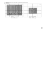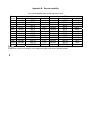
1
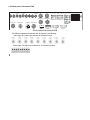
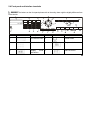
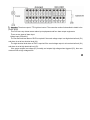
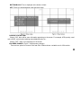
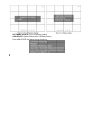
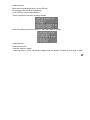
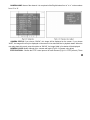
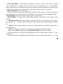
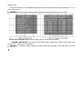
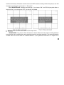
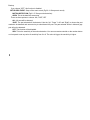
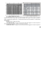
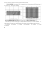
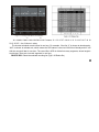
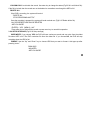
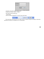
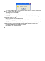
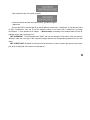
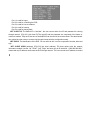
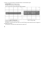
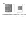
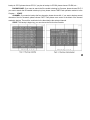
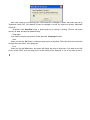
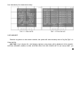
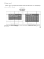
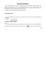
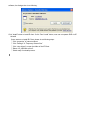
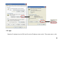
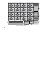
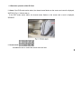
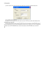
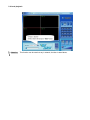
User’s manual for DVR
*This manual is tailored for MPEG4-100FPS/120FPS 9-channel and 16-channel digital video recorder
*This manual takes 16-channel digital video recorder as example
1
Before operation, we strongly advise you to read the user manual and keep it properly for later using.
This manual is an operation guide but not quality warranty. We may reserve the rights of amending the
typographical errors, inconsistencies with the latest version, software upgrades and product improvements,
interpretation and modification. These changes will be published in the latest version without special
notification.
2
Table of Contents
Digital Video Recorder (DVR) Introduction ..................................................................................................... 6
1.1 Product introduction .......................................................................................................................... 6
1.2 Features of this DVR ......................................................................................................................... 6
Installation Notice ......................................................................................................................................... 10
2.1 Check the accessories in the carton ............................................................................................... 10
2.2 Install the HDD ................................................................................................................................ 10
2.2.1 Install reminder...................................................................................................................... 10
2.2.2 Install tool ...............................................................................................................................11
2.2.3 Install process ........................................................................................................................11
2.3 Back panel and interface terminals ................................................................................................. 16
2.3.1 Back panel of 16-channel DVR ............................................................................................. 16
2.3.2 Back panel of 9-channel DVR ............................................................................................... 20
2.4 Front panel and interface terminals ................................................................................................. 21
2.5 Remote controller description.......................................................................................................... 24
2.6 Alarm cable connection ................................................................................................................... 28
Basic operation guide................................................................................................................................... 31
3.1 How to start the DVR....................................................................................................................... 31
3.2 Login and setup the system ............................................................................................................ 32
3
3.2.1 SETUP-SYSTEM .................................................................................................................. 35
3.2.2 SETUP-LIVE ......................................................................................................................... 40
3.2.3 SETUP-REC ......................................................................................................................... 43
3.2.4 SETUP-STORAGE ............................................................................................................... 51
3.2.5 SETUP-NETWORK............................................................................................................... 52
3.2.6 SETUP-SENSOR/ALARM .................................................................................................... 61
3.2.7 SETUP-AUDIO...................................................................................................................... 65
3.3 Function .......................................................................................................................................... 66
3.3.1 STATUS ................................................................................................................................ 66
3.3.2 AUDIO................................................................................................................................... 67
3.3.3 BACKUP& VIEW BACKUP ................................................................................................... 68
3.3.4 PAN/TILT............................................................................................................................... 75
3.3.5 ZOOM/FOCUS...................................................................................................................... 75
3.3.6 SEQUENCE .......................................................................................................................... 76
3.3.7 LOG LIST.............................................................................................................................. 77
3.4 Search record.................................................................................................................................. 79
3.5 SPOT .............................................................................................................................................. 84
Appendix ...................................................................................................................................................... 86
Appendix A Main Standard & Parameter chart.................................................................................... 86
Appendix B Record capability............................................................................................................. 90
4
Appendix C
The meaning of some abbreviation ................................................................................. 91
5
Digital Video Recorder (DVR) Introduction
1.1 Product introduction
This DVR is designed specially for CCTV system. It adopts embedded processor and embedded
operating system working with the high-powered code and decode chip. In addition, absorbing advanced IT
technology makes the system more stable, such as the audio code and decode technology, big capacity hard
disk, complying with the TCP/IP protocol,SoC, etc…
It is a stand alone unit, but also works on internet, to allow customer to have remote surveillance. It is
ideal for middle-risk to high-risk site surveillance system. Due to its good performance, it is widely installed
and used in Banks Industry, Telecommunication System, Electricity Power department, Law System,
factories, storehouses and uptowns, etc…
1.2 Features of this DVR
General
Video output: CVBS, S-VIDEO, VGA and SPOT monitor
Triplex operation : view/record/playback/remote operate at the same time
6
Various recording resolutions, D1,Half D1 and CIF
Support channel security by hiding live display
Display the local record state and the basic information
Remote controller equipped
Support two level password control: administrator and common user
Operation log recording and searching
Video system (PAL or NTSC) can be detected automatically and selected manually
Recording list can be deleted one by one or by all and locked to protect the important records
Support water mark technology
Format
Standard MPEG-4 compression format
Storage
Support to carry up to four IDE HDD simultaneously (Or three IDE HDD and one IDE DVD-RW/CD-RW)
Backup
Auto-play software automatically packed in backup files, and Auto-water-mark check in backup files to
assure files’ authenticness
Support backup via USB 2.0 to USB flash memory, or CDRW,DVD-RW to CD-R/DVD-R respectively
Support remote backup by “Net Client” through LAN or internet
Record and playback
Record modes: Manual, Sensor detection, Timer, Motion detection and Continuous
7
Support HDD recycle
Up to 16CH playback, fast forward(2X,4X,8X,16,32X,64X and 128X)and slow forward modes;
play the record frame by frame; jog shuffle to forward/backward function, which is including frame rate
adjusting
Support remote playback in “Net Client” through LAN or internet
Three record search mode: time search, event search, file search
Alarm
9/16 alarm inputs and 4 alarm outputs, TTL alarm output
PTZ control
Support decoder which communicates with RS485
Support speed dome
Support PTZ through network
Communication port
RS 485 equipped
Network
Support TCP/IP protocol
Support wide bandwidth network through modem (PPPOE)
Support static IP and dynamic IP (DHCP)
On time preview/playback/monitoring with audio signal through network
Support control PTZ camera through the network
8
Support IE browser, for remote view (automatically download active-x )
9
Installation Notice
Attention: Before connecting to the other equipments, please make sure that the device is powered off.
Do not hot plug in!
2.1 Check the accessories in the carton
Check accessories when you receive the machine, to make sure you have all the parts. Normally it shall
contain: a remote controller, a power cable, a CD-Rom with “Net Client” software, screws for installing HDD
2.2 Install the HDD
2.2.1 Install reminder
Please affirm the size of HDD needed and choose the suitable ones to install. If the origin DVR does not
have HDD, let the professional install/uninstall the device.
10
2.2.2 Install tool
One cross-screwdriver
2.2.3 Install process
⑴ Open the DVR by screwdriver
⑵ Set one as master and the other as slave if two HDDs are connected to one ATA interface!!!
Attention: Same HDD connected to parallel cable can not be set as master+master or slave+slave,
must be master+slave!!!
HDD setup: Take the HDD of Maxtor (DiamondMax Plus 8 ATA/133 40GB) as example.
Read the jumper cutline in the rear of HDD
Cap limit
CS Enable
DS(MASTER)
No jumper=DS(SLAVE)
11
Jump line area
The picture blow is the connection section of the HDD.
Jump line area
Jump line according to the cutline above
MASTER
SLAVE
The sequence of read/write data from HDD
The ATA interface which is near the motherboard center is the secondary interface, the next ATA
interface which is near the motherboard fringe is the primary interface. The sketch is in the following.
The HDD names that are shown in the DVR system are HDD A/B/C/D. The master HDD connected to
12
primary ATA interface is HDD A, the slave is HDD B. The master HDD connected to secondary ATA interface
is HDD C, the slave is HDD D.
The record sequence: HDD A→HDD B→HDD C→HDD D
Overwrite sequence: The sequence is irrespective with HDD. The DVR over write HDD from the oldest
record file when HDD is full.
Motherboard
⑶ Operation
① Put the HDD into the HDD fixation rack. If the user wants to install more than two HDD, please
install the HDD into the rack below first.
Fix the HDD by two screws on both sides
③ Connect the HDD cable. There are three interfaces on cable and each of them can be connected with
the master HDD or the slave HDD, motherboard. (There are 39 pins in two rows, 20 pins are in one row and
13
19 pins are in the other row). Make sure pins are plugged into interface exactly.
④ Connect the power supply to HDD
Sketch map of installation
Close the device cover and lock it by screws
Attention: ⒈ Please format the HDD before you using.
⒉ If the user wants to connect the CD/DVD driver to the ATA interface, please choose
the secondary interface, that is near the center of the motherboard. Furthermore, the CD/DVD driver
must be set as master, and the HDD which is connected to same ATA interface with the
CD-RW/DVD-RW must be set as slave.
⒊ Any CD/DVD driver connected to DVR must be set as master, containing USB CD/DVD
driver and IDE CD/DVD driver.
⒋ The CD/DVD driver connected to ATA interface can be viewed in the STATUS or STORAGE
menu of DVR, the CD/DVD driver connected to USB interface can not be viewed in the menu of DVR.
⒌ The CD/DVD driver is optional, depending on the user. If user connects CD/DVD driver to
ATA interface, the max number of HDD that connects to ATA interface is three.
14
1
2
First, put the HDD into the HDD fixation rack
Second, fix the HDD by two screws on both sides
4
3
Third, connect the HDD cable
Fourth, connect the power supply to HDD
Sketch map of installation
15
2.3 Back panel and interface terminals
Attention: The interfaces on the back panel please refer to the real object, there might be slightly
difference from below sketch.
2.3.1 Back panel of 16-channel DVR
CAM1
CAM2
CAM9
CAM10
CAM3
CAM4
CAM5
CAM11 CAM12 CAM13
CAM6
CAM14
CAM7
CAM8 AUDIO IN 1 AUDIO IN 2
ALARM OUT
ALARM IN
1 2 3 4 5 6 7 8 1 2 3 4
CAM15 CAM16 AUDIO IN 3 AUDIO IN 4
9 10 11 12 13 14 15 16
SPOT OUT
VIDEO OUT
S VIDEO
16
+
-
GND
RS-485
AUDIO OUT
LAN
Num
COM
USB
VGA
Back panel of 16-channel DVR
Icon
RS-232
Description
1
Video input 1-16
2
Spot output
3
Video output
4
S video output
5
Audio output
17
18
6
LAN port
7
Audio in 1-4
8
Alarm input1-16
9
Alarm output
10
Fan vent
11
Power plug
12
USB port
13
VGA port
14
RS 232 port(Null)
15
RS485 port
19
2.3.2 Back panel of 9-channel DVR
CAM1
CAM3
CAM2
SPOT OUT
CAM4
VIDEO OUT
AUDIO IN 1 AUDIO IN 2
CAM9
CAM7
CAM5
CAM6
S VIDEO
CAM8
ALARM IN
1 2 3 4 5 6 7 8 9
ALARM OUT
1 2 3 4
AUDIO IN 3 AUDIO IN 4
AUDIO OUT
COM
+
-
GND
RS-485
LAN
USB
VGA
Back panel of 9-channel DVR
The difference between 9-channel and 16-channel is as following:
Video input: The video input channel of 9-channel is nine.
Alarm input: The alarm input channel of 16-channel is sixteen.
20
RS-232
2.4 Front panel and interface terminals
Attention: The buttons on the front panel please refer to the entity, there might be slightly difference from
below sketch.
1
14
11
1
2
3
P/T
4
5
6
Z/F
12
7
8
9
AUDIO
7
MODE
BACKUP
0
Power
Number
4
Icon
5
6
LED
27
26
16
23
REC
17
MENU
2
28
15
13
FUNCTION
8
9
SEARCH
PLAY
10
Icon
STOP
FF
REV
INFOR
USB
18
21
19
22
20
25
24
Description
Number
Description
1
CD-RW/DVD-RW
2
Power button
3
Number button
4
Sequence button
5
Display
mode
shift button
6
Pan/Tilt control
21
7
Zoom/Focus
control
8
Audio on/off button
9
Backup button
10
Menu button
11
Function button
12
Status button
13
Leftward
14
Upward
15
Enter button
16
Rightward
17
Downward
18
Record button
19
Shuttle: to control
the DVR to play
the record frame
by frame.
20
Shuttle: to control the
playback speed
21
Search button
22
Play button
22
23
Fast Reverse
24
Fast forward
25
Stop
26
Remote
receiver
27
USB port
28
LED indicator lights, for
power,
HDD
and
backup, network status,
playback status and
record
status
respectively.
controller
Attention:
The CD-RW/DVD-RW is optional, depending on the user. If the user connects
CD-RW/DVD-RW to the ATA interface, the max number of HDD that connects to the ATA interface is three.
LED indicator lights:
The first light is on when the DVR is powered on;
The second light flickers when HDD is written or read;
The third light is on when backup in DVR;
The fourth light is on when a computer connects with the DVR via network;
The fifth light is on when the DVR is playing back;
The sixth light is on when the DVR is recording.
23
2.5 Remote controller description
Put the Battery into the Remote controller:
Open the battery cover of Remote controller
Put in two AAA batteries and make sure that they are not inserted upside down.
Put back the battery cover
The entire view of remoter controller
The buttons description:
Number
1
24
Icon
Description
Record button: Press this button to start recording if the DVR does not
record. Press this button to stop recording if the DVR is recording.
2
Backup button: Press this button, the DVR enters the backup menu
(Fig3.3.7 USB backup). The details will be given in Chapter 3.3.3:
BACKUP
3
Information button: Press this button to display status information of
the DVR on the screen (Fig3.3.2 Status view).
4
Number button: These number buttons are used for selecting channels
and other functions.
5
Full-Screen display mode. You can use CH+ or CH- button to switch the
channel. This also can be done by pressing number buttons.
6
Four-Screen display mode.
7
Sixteen-Screen display mode
8
Nine-Screen display mode
9
Menu button: Press this button to enter the setup menu (Fig3.2.2 Setup
menu), or return to previous menu level, or exit menu.
25
26
10
Search button: Press this button to enter to recording search page
11
Upward
12
Leftward
13
Rightward
14
Downward
15
SR is for Reverse when the DVR plays record while SF is for Forward
16
Change the channel one by one, “-” is used to change the channel from
16 to 1, and “+” is for changing the channel from 1 to 16
17
Fast reverse(There are seven options of speed to choose: 2X, 4X, 8X,
16X, 32X, 64X, 128X )
18
Play
19
Fast forward(There are seven options of speed to choose: 2X, 4X, 8X,
16X, 32X, 64X, 128X )
20
Stop
21
Zoom/Focus control
22
Pan/Tilt control
23
Audio switch
24
Log file button
25
Picture in picture: select the channel to display as small picture first, and
then press PIP button to enter PIP mode, the background picture is the
next channel. For example, If the user selects channel 10 first, and then
press PIP button, the screen will display as the Fig2.1.1 PIP showing. If
the display mode is PIP now, press the number button to select the small
picture.
26
Spot button: This button enable or disable the video output to call
monitor (spot monitor) in sequence.
27
POP: press this button first, and then press number button to select the
channel of big picture. For example: press POP button first, and then
press 5, the screen will display as the Fig2.1.2 POP showing.
28
Sequence button: press this button to make the DVR display channels in
turn.
If the Remote controller does not work, please check out the followings
27
Whether the battery’s anode and cathode are in the correct position or not
The battery is ran out of
Whether there is barrier between the Remote controller and DVR or not
Whether there are some signals transmitted by other devices disturbing the Remote controller or not
Attention: If the possibilities above are excluded, please contact with vendor to change the remote
controller
11
5
6
7
8
10
9
Fig2.1.1 PIP
2.6 Alarm cable connection
Example of alarm output connection:
28
10
11
Fig2.1.2 POP
12
Attention: The alarm output is TTL high level control. The connection method is described in details in the
picture above.
This DVR can carry sixteen sensor alarm input equipments and four alarm output equipments.
There are two types of alarm input:
Voltage input (5V and 0V)
The low electrical level alarm of DVR is required if the usual voltage output is at high electrical level (5V)
and alarm is set at low electrical level (0V).
The high electrical level alarm of DVR is required if the usual voltage output is at low electrical level (0V)
and alarm is set at high electrical level (5V).
If the sensor outputs low voltage (0V) normally, and outputs high voltage when triggered (5V), then user
must set DVR as high voltage alarm.
29
Open/Close input
N.O: Normal open. It will be closed when triggered. DVR must be set as low voltage alarm;
N.C: Normal close. It will be opened when triggered. DVR must be set as high voltage alarm.
30
Basic operation guide
3.1 How to start the DVR
Attention: Before power on the machine, please make sure the power input (110V/220V) of DVR is
eligible for local power supply, if not, please move the red flipper to the correct input.
If the power indicator light is off, please do as the following:
If the DVR is not connected to the AC source, please connect it. Afterwards the DVR will be powered
immediately. However, if the problem is remaining, please do as the next step.
Switch up the power supply in the back panel, the DVR will start.
The power indicator light is on DVR is powered on, and the word — “Loading……” appears on the screen.
That indicates the DVR is initializing and will enter the live preview soon.
A password is required to access to the menu, you can not enter the next level menu until you type in
correct password. In order to avoid password being spied, the password you input is displayed as “*” while
you are inputting the password.
Only administrator, access the menu with administrator password can setup and modify the configuration,
change administrator password and normal user password.
Normal user can view the live image and playback record by inputting normal user password when
31
machine is initialised. (The detail of admin password and user password are described in chapter 3.2.1
SETUP-SYSTEM).
Input default password-“0000” to visit the setup menu if you start the DVR, assuming that you have not
changed the password or you have recovered the default setting.
The date, time and channel name are displayed on the screen.
Symbol
Meaning
LIVE
Live state
REC
Record(Manual or continuous)
R
A
Alarm record
R
M
Motion record
HDD
The use ratio of HDD
V-LOSS
Video loss
USB
USB equipment connected
Press the number key to enter the single-screen mode. If you want to view the image from channel 1 to
channel 16, please press the corresponding number key. For example: To see the picture in channel 3, press
the key 3; to see the picture in channel 13, press the key 10+ first and press the key 3 second.
3.2 Login and setup the system
The menu structure chart:
32
ADMIN PASSWORD
USER PASSWORD
PASSWORD CHECK
SYSTEM
TIME SETUP
SEQUENCE DWELL[FULL]
SEQUENCE DWELL[QUAD]
CAMERA NAME
CAMERA STATUS
LIVE
CAMERA COLOR
PTZF PROTOCOL
PTZF ID
TIME FORMAT
TIME OSD FORMAT
TIME STAMP FORMAT
CURRENT STATUS VIEW
VGA PREQ CHANGE
SOFTWARE UPDATE
DEFAULT SETUP
SPOT DWELL
MENU
SPOT QUAD DWELL
REC PROPERTY
VIDEO STANDARD
REC OPTION
RECORD
EVENT REC
TYPE
STORAGE
NETWORK
NET PASSWORD
DELETE REC
NET CLIENT PORT
LOCK/UNLOCK REC
NET CLIENT ID
DELETE ALL REC
NET DVR ID
SENSOR TYPE
NET CLIENT ADDR
NETWORK THROUGHPUT
SENSOR/ALARM
SCHEDULE REC
ALARM MOTION MANAGER
ALARM SENSOR MANAGER
ALARM BUZZER
ALARM OUTPUT
AUDIO
ALARM OUT PERIOD
33
There are two users in the origin DVR system. One is Admin which has highest priority to set system’s
configuration and whose password is “0000”, the other is common user which is just allowed to see the live
play and the playback picture. And it does not have the right to change its password, which is done by Admin
users.
Operation:
Press the Menu key and enter the ADMIN password, and then you will see the setup menu (Fig3.2.1
Setup menu). Use the “Up” “Down” “Right” and “Left” to shift cursor, the item selected will be displayed in
yellow.
34
Press the “Enter” key to enter the sub-menu and press the “Menu” key to get back to the main menu.
3.2.1 SETUP-SYSTEM
The menu is as above: (Fig3.2.2 System setup)
ADMIN PASSWORD: Administrator password is initialized as “0000”, only the administrator has the right
to change it which is comprised of four numbers between 0 and 9 (Fig3.2.3 Setup admin password).
USER PASSWORD: Common user password is initialized as “0000” as well. However, only the
35
administrator is authorized to change it which is comprised of four numbers between 0 and 9.
PASSWORD CHECK: If you choose “ON”, users have to input the password before entering menu. You
can setup the DVR’s configuration if you enter the administrator password. And the common user password
just allows you to the check the live image or saved record; if you choose “OFF”, there is no limitation on
configuration. Anyone can enter the system directly without password. (Fig3.2.4 Password check)
TIME SETUP: Use the “Up” “Down” “Left” and “Right” buttons to move the cursor and use the number key
in panel or remote controller to modify the value. If the DVR is recording or playing back the visit to this menu
is not allowed unless the recording or playing back is stopped. (Fig3.2.5 Time setup)
TIME FORMAT: YY/MM/DD: Asian format, Year/Month/Day; DD/MM/YY: European
Day/Month/Year; MM/DD/YY: American format, Month/Day/Year. (Fig3.2.6 Time format)
TIME OSD FORMAT: Time format of live-image.
TOP-WHITE: Time is displayed on top in white
TOP-BLACK: Time is displayed on top in black
BOTTOM-WHITE: Time is displayed at the bottom in white
BOTTOM-BLACK: Time is displayed at the bottom in black
OFF: There is no time displayed in the live-image.
TIME STAMP FORMAT: Time format of plays back mode.
TOP-WHITE: Time is displayed on top in white
TOP-BLACK: Time is displayed on top in black
BOTTOM-WHITE: Time is displayed at the bottom in white
36
format,
BOTTOM-BLACK: Time is displayed at the bottom in black
OFF: There is no time displayed in the play back mode.
CURRENT STATUS VIEW:
Choose “ON”, there will be some information appearing on the screen. For example, HDD quantity, used
ratio of HDD, record mode including manual/alarm/motion etc…
Choose “OFF”, there is no information on the screen.
VGA PREQ CHANGE: (Fig3.2.7 VGA frequency change)
There are two options to choose: 50Hz and 60Hz. Please choose a suitable one for VGA monitor.
37
SOFTWARE UPDATE: (Fig3.2.8 Software update)
USB UPDATE: Update firmware from USB flash memory
Press USB UPDATE and below screen will pop up
38
Update firmware:
Make sure the updating firmware is in the USB disk
Do not power off the DVR during updating;
Press “ENTER” button to start updating.
Then the system will check the updating firmware
When the updating firmware is found O.K., the system starts to update.
Update process:
Erase the former file;
Check the space for update;
When the space is ready, the software update starts, the percent of update is in the right. It takes
39
about two minutes to update.
When the erase, blank check and update are done, system will check the new program which is
written just now.
After the program check is done, the system will restart. So far, USB update is over.
NETWORK UPDATE: The update information is in network, please choose this option
Server IP: The IP address of the network where the firmware is in.
File name: The file name of the firmware.
After filled in the two options above, move cursor to “UPDATE”, press “ENTER” button to begin update
from network. It is the same with USB update that the DVR will restart when the software update completed.
Attention: Please make sure the IP address and the file name are correct.
DEFAULT SETUP: recover the origin configuration setup.
3.2.2 SETUP-LIVE (Fig3.2.9 Setup live)
SEQUENCE DWELL(FULL):Setup the interval period of single channel switching, there are 9 options for
users, from 0 second to 9 seconds.
SEQUENCE DWELL(QUAD):Setup the interval period of four-channel switching, there are 9 options for
users, from 0 second to 9 seconds.
40
CAMERA NAME: Name of the channel. It is comprised of the English letters from “a” to “z” or the numbers
from “0” to “9”.
CAMERA STATUS: If you choose “SHOW”, this image will be displayed on the screen. If you choose
“HIDE”, the image will not only be displayed on the screen in live status but also in playback status. When the
user plays back this record, setup this option as “SHOW”, the image hided in live status will be displayed.
CAMERA COLOR: Modify channel color, contrast and bright. (Fig3.2.10 Camera color adjust)
PTZF PROTOCOL: Choose the PTZF control protocol for each channel (Fig3.2.11 PTZF protocol). There
41
are seventeen options for users: PELCO_D-2400, PELCO_D-9600, PELCO_P-4800, PELCO_P-9600,
SCC641-9600, SCC641-19200, SK2161-9600, CNB_102-9600, ADTECH-4800, 15-CD51M-2400, Chubb
iSD-9600, COP1-2400, COP1-4800, COP1-9600, COP1-19200, COP2-9600, 15-CD51M-2400,
DSC230-9600
PTZF ID: Setup the PTZF address, you can choose from “000” to “255”.
SPOT DWELL: 16 channel pictures circulate from 1 to 16. Press “Enter” button to get access to the
configuration setup menu to modify the interval time between two channels switch. The user can use the
number buttons to choose the options—from“0” to “9” seconds. (Fig3.2.12 Spot dwell)
42
SPOT QUAD DWELL: Channel-switching circulates from quad 1 to quad 4 (The order is: channel
1,2,3,4→channel 5,6,7,8 →channel 9,10,11,12→channel 13,14,15,16→channel 1,2,3,4→…), press “Enter”
button to get access to the configuration setup menu to modify the interval time between two sets of pictures
switching. The user can use the number buttons to choose the options—from“0” to “9” seconds.
VIDEO STANDARD: Setup the video style.
There are four options to choose: AUTO-DETECT, SWITCH, NTSC, and PAL. The DVR can detect the
video automatically if you set this option as AUTO-DETECT, you can also set the video standard manually.
3.2.3 SETUP-REC: Setup the parameter of record (Fig3.2.13 Setup record)
REC-PROPERTY: It contains REC RESOLUTION, QUALITY and RATE (Fig3.2.14 Setup record
property).
REC RESOLUTION: Higher the resolution is, clearer the picture is. The resolution from low to high is:
PAL:360*288(CIF),(720*288)HalfD1, (720*576) D1; NTSC: (360*240) CIF, (720*240) HalfD1, (720*480)
D1.
QUALITY: There will be four options to choose: low, normal, high and best. Higher the quality value is,
better the picture is.
RATE: The frame rate. If you choose 8, the picture recording rate is 8 frames per second.
The maximum of RATE is different when the REC RESOLUTION is different. For example:
The record resolution is 720*576(PAL)/720*480(NTSC), there are five frame rates to choose: 0, 1, 2, the
maximum is 2.
The record resolution is 720*288(PAL)/720*240(NTSC), there are six frame rates to choose: 0, 1, 2, 4, the
43
maximum is 4.
The record resolution is 360*288(PAL)/360*240(NTSC), there are seven frame rates to choose: 0, 1, 2, 4,
8, the maximum is 8.
Attention: These three factors above decide the quality of picture and the use ratio of HDD.
SETUP- REC OPTIONS: Setup of record option (Fig3.2.15 Setup record option)
RECORD CONTINUOUS: If you choose “ON”, DVR records continuously in HDD recycle mode. If you
choose “OFF”,this function is disabled.
Attention: In Continuous mode, Manual and Alarm record are activated at the same time, the DVR
44
records continuously. If the alarm record occurred, the DVR remains recording continuously and you can find
the alarm event through “event search” or “file search”.
PLAY DEINTERLACE: Interlace scan and play. If you choose “ON”, the DVR will play back after an
internal of line. If you choose the “OFF”, this function is disabled.
Attention: This function is more useful in VGA output mode.
WATER MARK: If you choose “ON”, this function is active. Water mark can protect recording files from
being modified, as the modification can be technically traced by checking watermark. The system will add the
invisible code to the record when the “WATER MARK” is on; the particular introduction is in Chapter 3.3.3
45
Backup.
If you choose “OFF”, this function is disabled.
SETUP-REC-EVENT: Setup of the event record (Fig3.2.16 Setup event record)
MOTION DETECTION (Fig3.2.17 Setup motion detection):
AREA: This is the detection area setup
There are three options to choose: ALL, PART, OFF
ALL: All area will be detected.
PART: The part selected will be detected. Use the “Up” “Down” “Left” and “Right” to choose the part
needed to be detected and use enter key to select/cancel the part. The part selected will be in blue and gray
part will not be detected.
OFF: This function will be disabled.
SEN: This is the sensitivity of the motion detection. You can use remote controller or the number button
on front panel to set any value of sensitivity from 0 to 9. The value is bigger, the sensitivity is higher.
46
[SETUP-REC-EVENT(S/D)]
Fig3.2.18 Setup sensor detection
SENSOR DETECTION: Each channel matches a relevant Sensor, for example, Channel 2 is linked to
Sensor 4, if the Sensor 4 gives alarm, the alarm information will be given on the picture by channel 2
(Fig3.2.18 Setup sensor detection), the “□” means that the channel can not be detected, “V” means that the
channel can be.
OPTIONS: (Fig3.2.19 Setup record time)
POST-RECORD TIME: The length of the record time after alarm triggered. You have five options to
choose: 10 seconds, 30 seconds, 1 minute, 5 minutes and 10 minutes.
PRE-RECORD TIME: The length of the record time before alarm triggered. You have five options to
47
choose: 2 seconds, 4 seconds, 6 seconds, 8 seconds and10 seconds.
POP-UP SCREEN: If you choose “ON”, the image will be in full screen when the DVR gives alarm. If
you choose “OFF”, this function is disabled.
SETUP-SCHEDULE-REC: Setup of schedule record (Fig3.2.20 Setup schedule record)
Press enter key to visit the menu (Fig3.2.21 Setup schedule record time). “O” means unselected, “V”
means selected. Use enter key to switch the status and use menu key to get back to upper level menu.
SU: Sunday
MO: Monday
TU: Tuesday
WE: Wednesday
TH: Thursday
FR: Friday
SA: Saturday
48
[SCHEDULE REC-CH 4]
SU
MO
TU
WE
TH
FR
SA
ALL DAY
AL
Fig3.2.21 setup schedule record time
2
1
“0 1 2 3 4 5 6 7 8 9 0 1 2 3 4 5 6 7 8 9 0 1 2 3” means: “0 1 2 3 4 5 6 7 8 9 10 11 12 13 14 15 16 17 18 19
20 21 22 23”— the 24 hours in a day.
The shortest schedule record interval is one hour. For example, if the first “2” is chosen at abscissa axis,
“MO” is chosen at ordinate axis, which means the DVR starts to record at 2:00 AM on Monday and till 3:00
AM; the record will last for one hour. The record file in HDD is divided into many segments, whose length is
ten minutes. There are six record segments in one hour.
DELETE REC: Delete the selected recording list (Fig3.2.22 Delete file)
49
Press enter key to visit the menu, information is given below (Fig3.2.23 Information of deletion)
“DELETE FILE 0171 200 60407_170000 15AS D U
ARE YOU SURE?
[ENTER]→ YES [MENU]→ NO”
Press enter key to delete this record or press menu key to quit deleting
“0171 200 60407_170000” is a record name.
“U” means unlock, if “U” is displaced by “L”, this record is locked and can not be removed. Please refer to
Appendix C for the abbreviations explain.
50
LOCK/UNLOCK: Lock/unlock the record. Use enter key to change the status (Fig3.2.24 Lock/Unlock file).
If the file is locked, then the record can not be deleted or overwritten even though the HDD is full.
DELETE ALL:
If the DVR is recording, the system will remind
“DELETE ALL
STOP RECORDING AND TRY”
Once the recording is stopped, the system will send reminder as: (Fig3.2.25 Delete all the file)
“ALL RECORDED FILES WILL BE DELETES
ARE YOU SURE?
[ENTER]→ YES [MENU]→ NO”
Press enter key to delete all the record or press menu key to cancel this operation.
3.2.4 SETUP-STORAGE (Fig3.2.26 Setup storage)
OVER WRITE: If you choose YES, the DVR will have continuous record and over write from the oldest
file when HDD is full. The DVR overwrites file from the oldest file. If you choose NO, the DVR will stop
recording when the HDD is full.
FORMAT: Use the “Up” and “Down” key to choose HDD that you want to format. A hint pops up after
pressing “enter”.
“DISK HDD-*
MOUNTED
ARE YOU SURE?
51
[ENTER]→ YES [MENU]→ NO”
(* represents A,B,C,D)
Press enter key to format the HDD, Press menu key to cancel this operation.
Attention: The format time depends on the HDD capability, bigger HDD takes longer time. Normally, a
40G HDD takes about eighty seconds. If CD/DVD driver connected to ATA interface, there will be three HDDs
and one CD-ROM displayed.
3.2.5 SETUP-NETWORK (Fig3.2.27 Setup network)
TYPE:
52
STATIC: Static IP address. Push “Up” “Down” “left” “Right” to move the cursor among the digits and
push ADD or DEC key to modify the IP address. (Fig3.2.28 Setup static IP).
DYNAMIC: Dynamic IP address. Press enter key to visit the menu, the system will display “Please
wait” for a while. Then, the IP address which is assigned by network will be displayed on the screen. If the
DVR failed to connect the network, it will display the information below: (Fig3.2.29 DHCP setting failing)
DHCP SETTING FAIL
CHECK YOUR NETWORK
Attention: If the network DVR is connected to one of the following items, we recommend use Dynamic.
53
The local area network has DHCP server
The DVR can get IP address automatically from internet
PPPOE: Connect to network by ADSL modem. “Name” is your ADSL account and “Auth” is your
password.
DDNS (Fig 3.2.30 DDNS)
54
Dynamic domain service. To use this function, user need to get a domain from the ISP, whose protocol
is packed in this DVR, as above list .Please note that the actual ISP list may be different from each Vendor,
please consult your local vendor on how to get the domain if different from below example. Take the
“dns2p.com” as example to introduce:
Register
Register in the web.
Fill out the IE address column with www.dns2p.com and Click
to enter the website. Click “New
user” in the right of home page to register. For example: User ID is “abc”, password is “123456”.
55
Login
Return to home page after registering successfully. Click “Account manager” in the right of home page to
login.
56
Username is User ID set before, which is “abc”.
Password is set before, which is “123456”.
Click “Enter” button after filling out.
Domain setup
Click the “Domain management” in the left to setup the domain.
Enter the domain in the blank and click “submit” button, the system will pop up a dialogue to show that
add domain successful. For example, set “dvr” as the domain.
57
The length of probationary period is one month. If user wants to use it over one month, please click the
“Buy now” in the right of home page to pay for it.
Setup in the DVR (Fig 3.2.30 DDNS)
DOMAIN: The domain is set in chapter 3. —Domain setup. According to the example before, the
domain is “dvr.dns2p.com”.
USER ID: The user name of register, which is ser in chapter 1. —Register in the web. According to the
example before, the user ID is “abc”.
GROUP ID: The name of the computer workgroup.
PASSWORD: The password is set in chapter 1. —Register in the web. According to the example
before, the password is “123456”.
ACTIVATE: Choose the name of website. According to the example before, the website is “dns2p.com”.
Then the DVR begins to connect to network and the system displays a sentence—“PLEASE WAIT”.
About two minutes later, the result is displayed in the screen.
If the connection is OK, the system prompts:
58
If the connection fails, the system prompts:
Check the network and the information before, and then try again.
Application
Connect the DVR to internet and fill out the IE address column with “*.dns2p.com” to visit the web client
of DVR. Furthermore, user can fill out the address column of net client with “*.dns2p.com” to remote
surveillance. “*” is the domain set in chapter —Domain setup. According to the example before, fill the IE
address column with “dvr.dns2p.com”.
NET PASSWORD:The initial password is “0000”, the user can change it in this menu. If the user name is
“NetUser” when the user login in the computer through network, the corresponding password is set in this
menu.
NET CLIENT PORT: Distribute net client port for each function. If router is used in the network, the router’s
port which is displayed in this menu must be opened.
59
Port 1 is used for logon;
Port 2 is used for controlling the DVR;
Port 3 is used for live surveillance;
Port 4 is used for backup;
Port 5 is used for playing back.
NET CLIENT ID: The default ID is “NetUser”, the user can set other four ID and password for viewing
through network. (Fig3.2.31 Net client ID).The login-ID and the password are composed of the letters or
number at random. Only the ID set here or the default ID can be used in the remote viewer. The administrator
can restrict the other users to remote view through internet with this configuration setup.
NET DVR ID: The identification of the DVR. You can edit it at will, it can be composed of number, letter and
sign.
NET CLIENT ADDR (address) (Fig3.2.32 Net client address): Fill those options with the network
information needed. Use the “Up” “Down” “Left” “Right” and enter key to fill the blank. “<000.000.000.000>”
means that any IP address can access the DVR through network. The user can set ten IP address to restrict
60
other IP access the DVR.
NETWORK THROUGHPUT: To setup the transfer speed of DVR in the network. There are nine options to
choose: unlimited, 64KBPS, 128KBPS, 256KBPS, 512KBPS, 1MBPS, 2MBPS, 4MBPS, 10MBPS. User can
choose the option according to the demand (Fig3.2.33 Setup net work throughput).
3.2.6 SETUP-SENSOR/ALARM (Fig3.2.34 Setup sensor/alarm)
SENSOR TYPE
Press enter to visit the next level menu and there are two options to choose: NO and NC.
“NO” means normal open. If “NO” is chosen, the DVR will alarm if the alarm at low level.
61
“NC” means normal close. If “NC” is chosen, the DVR will give the alarm if the alarm is at high level.
ALARM MOTION MANAGER (Fig3.2.35 Alarm motion manager)
“□” means unselected, “V” means selected, “Abscissa” means the channel number, “Ordinate” means
annunciator number.
Every channel is able to trigger multiple alarms. For example, if user selects alarm 1, alarm 2 and alarm 3
for channel 1, then once there is motion detected in channel 1, alarm 1, alarm 2, and alarm 3 send alarm
signal in the same time.
Every alarm can work for multiple channels. For example, if user selects channel 1, channel 2 and
62
channel 3 for alarm 1, then any of the 3 channel detects motion event, alarm 1 will send signal.
ALARM SENSOR MANAGER (Fig3.2.36 Alarm sensor manager)
“□” means unselected, “V” means selected, “Abscissa” means the sensor number and “Ordinate” means
annunciator number.
Every sensor is able to trigger multiple alarms. For example, if user selects alarm 1, alarm2 and alarm 3
for sensor 1, then once sensor 1 is activated, alarm 1, alarm 2 and alarm 3 send alarm signal in the same
time.
Every alarm can work for multiple sensors. For example, if user selects sensor 1, sensor 2 and sensor 3
63
for alarm 1, any of the 3 sensors is activated, the alarm 1 will send alarm signal.
ALARM BUZZER (Fig3.2.37 Alarm buzzer)
ON: Start the buzzer when DVR gives alarm
OFF: The buzzer will not be triggered when DVR is alarming
ALARM OUTPUT (Fig3.2.38 Alarm output)
ON: Alarm on. Only when the alarm output is on, the DVR will give alarm when the sensor is triggered or
the motion event occurs.
OFF: Alarm off. The DVR will not send alarm when output is off.
64
ALARM OUT PERIOD (Fig3.2.39 Alarm output period)
Alarm continuing time. There are five options to choose: 30 seconds, 1 minute, 3 minutes, 10minutes and
Continuous.
3.2.7 SETUP-AUDIO
“■” means unselected, “V” means selected, “Abscissa” means the channel number and “Ordinate”
means audio output number. (Fig3.2.40 Audio output)
65
There are four audio input ports and one audio output port in all. One audio input matches one channel.
For example, if user selects audio A for channel 1, channel 1 will record audio A.
3.3 Function
Press the Function button to enter the basic function menu (Fig3.3.1 Function menu), which contains the
following items:
STATUS
AUDIO
BACKUP
PAN/TILT
ZOOM/FOCUS
LOG LIST
3.3.1 STATUS
Press the Info button on the remote controller, the screen will display the firmware version number, HDD
status, Network status and record information. (Fig3.3.2 Status view) If CD/DVD driver connected to ATA
66
interface, there will be three HDDs and one CD-ROM displayed.
[STATUS]
S/W VER: V1.0.10-tv_16
(06/05/08 10:07)
[HDD] A: 150G(63%) B: NONE
C: NONE
D: NONE
NETWORK:
MAC: 00.0E.B5.00.06.32
DDNS: SERVER (null) FAIL
[REC]
SIZE
720*576
CH RA QUAL CH RA QUAL CH RA QUAL CH RA QUAL
1 2 BEST 5 2 BEST 9 2 BEST 13 2 BEST
2 2 BEST 6 2 BEST 10 2 BEST 14 2 BEST
3 2 BEST 7 2 BEST 11 2 BEST 15 2 BEST
4 2 BEST 8 2 BEST 12 2 BEST 16 2 BEST
Fig3.3.2 Status view
3.3.2 AUDIO
AUDIO ON: Activate the audio output; MUTE: Disable the audio output
67
3.3.3 BACKUP& VIEW BACKUP
Backup
Press the Backup button (Fig3.3.3 Setup backup). This DVR support five media types: CD-R, CD-RW,
DVD-R, DVD- RW, USB-MEMORY (Contain USB disk and mobile hard disk), and support backup to
DVD-RW, CD-RW, internally and as well as USB externally. Please refer to list of compatible DVD-RW,
CD-RW, which may be updated at times.
MEDIA TYPE: Press Enter button to access the next menu (Fig3.3.4 Setup media type), if you plan to
68
backup in CD-R, please choose CD-R; if you plan to backup in CD-RW, please choose CD-RW, etc…
BACKUP BASE: If you want to search the file needed to backup by file name, please choose FILE; if
you want to search the file needed to backup by time, please choose TIME. Each operation method is in the
Chapter— START.
CHANNEL: If you want to backup the four channels, please choose ALL, if you want to backup several
channels of the four channels, please choose PART. Then please move cursor to the blank of the channel
needed to backup. There will be a white dot in the blank before the selected channel.
START: The backup’s beginning; you can choose the file from the file table.
69
If the backup base is “FILE”, the “START” choose menu is as Fig3.3.5 Backup start (file) showing.
If the backup base is “TIME”, the “START” choose menu is as Fig3.3.6 Backup start (calendar) and
Fig3.3.7 Backup start (time) showing. First, choose the date, second, choose the time.
[BACKUP-TIME]
USB BACKUP
USB BACKUP
HOUR:
MIN:
: : 000000
TIME
50%
Fig3.3.8 USB Backup process
END: The backup’s end, the setup method is the same as the START.
After the setup of MEDIA TYPE, FILE FORMAT, BACKUP BASE, CHANNEL, START, END finished, the
DVR is ready to backup.
BACKUP
Press the BACKUP button, the DVR begins to backup; there is a schedule of backup progress on the
70
screen in the same time with backup. The USB backup process is as the Fig3.3.8 USB backup process
showing, that is the same as backup with the CD/DVD driver.
When the backup is over, a dialogue box will pop up. If the user backup in the USB memory, the sentence
in the dialogue box is as following:
“FLASH
BACKUP OK”
So far, the backup is completed.
Cancel
If the user wants to change the backup file, please move cursor to “CANCEL” and press “ENTER” button
to cancel the file selected before.
Attention:
Only the CD-R or CD-RW can be used when the user backup file with CD driver;
Only the CD-R, CD-RW, DVD-R or DVD-RW can be used when the user backup file
with DVD driver.
View backup
The software to view the backup recording is packed automatically in the file.
Icon of the backup viewer:
— “Backup_viewer”
Brief introduction of buttons
71
: Play
: Stop
: Step backward
: Pause
: Fast backward
: Step forward
: Fast forward
: Verify the record is changed or not
: Snap shot
: Volume control
: Number button
/
/
/
:1-channel/4-channel/9-channel/16-channel mode
You can use number button to choose the channel which you want to see.
The main menu of the Backup viewer:
72
Particular introduction of W.M Check, SnapShot.
W.M Check (Water Mark Check)
When the backup file is paused, click this button to check water mark:
73
After a few minute, the result will pop up. If the backup file is changed or moved, the system will pop up
“Watermark Check Fail”, if the backup file was not changed or moved, the system will prompt “Watermark
Check Ok”.
SnapShot: Click SnapShot button, a picture pops up for saving or printing. The user can select
directory to save, and also can print it directly.
Snap Again:
If you want to snap the next picture, Please press the “Snap Again” button.
Save:
When you click the “OK” button, a dialog box pops up for saving place. Fill the file name and choose the
file type, then click “Save” of the dialog box.
Print:
When you click the Print button, the system will display the setup of the printer. If you want to print this
picture, press PRINT, then the dialog box of printer setup will be displayed. If you do not want to print it,
74
please press CANCEL.
3.3.4 PAN/TILT
Move cursor to PAN/TILT in the function menu, press Enter button to access this menu (Fig3.3.9
PAN/TILT) to control the Fast Speed Dome. The particular operation is as following:
Switch to the channel which connects to the Fast Speed Dome video output. Through the “Up” “Down”
“Left” “Right” button to control the Fast Speed Dome to swing up, down, left or right, press “Enter” button to
stop swinging.
The user can also enter this menu directly by pressing the PT button on the front panel or the remote
controller.
3.3.5 ZOOM/FOCUS
Move cursor to ZOOM/FOCUS in the function menu, press Enter button to access this menu (Fig3.3.10
ZOOM/FOCUS) to control the Fast Speed Dome. The particular operation is as following:
Switch to the channel which connects to the Fast Speed Dome video output. Through the “Up” “Down”
button to control the Fast Speed Dome to zoom-in and zoom out each. Through “Left” “Right” button to
control Fast Speed Dome’s short and long focus each.
The user can also enter this menu directly by pressing the PT button on the front panel or the remote
75
controller.
PAN/TILT
ZOOM/FOCUS
Z+
F+
AUTOPAN
ENTER
<<Ch1>>
Fig 3.3.9 PAN/TILT
FZ<<Ch1>>
Fig3.3.10 ZOOM/FOCUS
3.3.6 SEQUENCE
Press “SEQ” button to enter the sequence play status.
If the current menu is the image of a single channel, press “SEQ” button to play the sixteen channels
one by one circularly.
If the current menu is the image of sixteen channels, press “SEQ” button to play the sixteen channels
76
four channels by four channels circularly.
3.3.7 LOG LIST
Press the Log button on the remote controller, the system will enter the setup menu of log file (Fig3.3.11
Setup log file).
LOG FILE: If you choose ALL, the following options in the picture will be displayed, which contains:
MOTION, SENSOR, ALARM, V-LOSS, SYSTEM, HDD, FLIE, DB, POWER, NET. If you choose PART, you
77
should choose the option needed manually. There is a white dot in the blank after the option selected.
FROM: The beginning time of the log file, you can use the number key to change the time.
TO: The end time of the log file, you can use the number key to change the time.
Press the OK if you setup above over, the system will enter the event log view (Fig3.3.12 Event log view):
Use “Up” “Down” to move the cursor to the log file needed. If there are too much log list, user can use “<”
button to page up, use “>” button to page down, use “《” button to jump to the last list, and press “》” button to
jump to the first list. Press “Enter” button to see the explanation. (Fig3.3.13 Explanation) Press “Enter” button
again to return to the event log list menu.
EVENT EXPLAIN
1818 060704: 151610 FL DEL: / hdd b/ 20060629_081000_nCm.ps
The particular introduction of each word above:
1818: The number of the deleted file.
060704: The date to delete the file.
151610: The time to delete the file.
FL: It means that file loss event occurred.
DEL: It means that the file was deleted.
Hdd: It means the file was deleted from the hard disk.
20060629_081000_nCm.ps: The file name.
78
3.4 Search record
Press the “Search” button on the remote controller, there are three search modes which will be displayed
on the screen (Fig3.4.1 Search)
TIME SEARCH
EVENT SEARCH
FILE SEARCH
Attention: Search all recording by time search or file search, search all event recording by event
79
search.
TIME SEARCH:
Attention: All the record can be searched in this menu.
Operation:
Date choose:
Press enter to access the CALENDAR TIME menu, Use “Up” “Down” “Left” “Right” to move cursor to the
date needed to search.(Fig3.4.1 Date choose). The time which had event record is shown as yellow font.
<<2006-05>>: Year-Month
<<: Backward, when the cursor moves to this sign, it will be in yellow, then press enter to make the month
backward. For example: the current time is 2006-05, press Enter once, the time will be changed to
2006-04.Press enter again, the time will be changed to 2006-03.
>>: Forward, when the cursor moves to this sign, it will be in yellow, then press enter to make the month
forward. For example: the current time is 2006-05, press Enter once, the time will be changed to 2006-06.
Press enter again, the time will be changed to 2006-07.
Time choose
Below the Year-Month setup, there is the calendar of one month under the Year-Month setup. The date
in green has record file, press enter to approach the time choose menu. (Fig3.4.2 Time choose).
The time displayed in green has record file. Use “Up” “Down” “Left” “Right” to move to the idiographic
time—hour and minute.
Press “Enter” to play the record after the time has been selected.
80
Press Enter button to view the record chosen, the “Forward” “Backward” “Play/pause” buttons can be
used to control the record. Press “stop” button to get back to live picture.
EVENT SEARCH
Attention: Only the alarm event and motion event record can be searched in this menu.
Operation:
Select the date, whose method is the same as TIME SEARCH. The time which had event record is
shown as yellow font.
Press “Enter” to access the event menu after selecting time. (Fig3.4.3 Event choose).
Analyze the record information. Take one of the event records information as example.
The meaning of the words:
“0691 060517:113145 FL MD 06”
“0691”: Serial number
“060517”: Date, the first and the second stand for year, the third and the fourth stand for month, the fifth
and the sixth stand for day. “060517” means may 17th, 2006.
“113145”: Time, the first and the second stand for hour, the third and the fourth stand for minute, the fifth
and the sixth stand for second. “113145” means 11:31:45.
“MD”: Motion detection.
“06”: The length of record time.
Select the record and press “Enter” button to view this record.
Use “Up” “Down” to choose the event record, press enter button to view the record chosen, The
81
“Forward” “Backward” “Play/pause” buttons can be used to control the record. Press “stop” button to get back
to live picture.
If there are too many event lists, user can move to the page needed though “PGUP” “PGDN” “LAST”
“FIRST”, the meaning of these signs and shortcut keys are in the following table.
[SEARCH-TIME]
HOUR:
MIN:
TIME: 00: 00: 00
Fig3.4.2 Time choose
82
Sign
Meaning
Shortcut key
PGUP
Page up, to the frontal
Right button
PGDN
Page down, to the next
Left button
LAST
To the last page
Backward button
FIRST
To the first page
Forward button
FILE SEARCH
Attention: All the record can be searched in this menu.
Operation:
Select the date, whose method is the same as TIME SEARCH. The time which had event record is
shown as yellow font.
Press “Enter” to access the play file list. (Fig3.4.4 File search)
Analyze the record information. Take one of the file records information as example.
The meaning of the words:
“194 20060517_113206 46S D L W”
“194”: Serial number
“20060517”: Date, the ex-four digitals stand for year, the fifth and the sixth stand for month, the seventh
and the eighth stand for day. “2006060517” means may 17th, 2006.
“46S”: The length of record time.
“D”: Resolution, D means the 720*576 in PAL or 720*480 in NTSC. Please refer to Appendix C for the
abbreviations explain.
“L”: Lock. Please refer to Appendix C for the abbreviations explain.
“W”: Water mark. If the option of “water mark” is set as “ON’, the word of “w” would be displayed in the file
search menu.
83
Select the record and press “Enter” button to view this record.
Use “Up” “Down” to choose the file record, Press enter button to view the record chosen, the “Forward”
“Backward” “Play/pause” buttons can be used to control the record. Press “stop” button to back to live picture
If the event file list is too much, user can move to the page needed though “PGUP” “PGDN” “LAST”
“FIRST”, the meaning of these signs and shortcut keys is in the table above.
The record was divided into many sections automatically. The default length of one section is ten minutes
(600 Seconds). Length may be shorter than 1 hour, depending on actual motion recording, alarm recording
and schedule setup.
3.5 SPOT
Connect the DVR to a SPOT monitor by the SPOT port first, and then press the “SPOT” button on the
remote controller to setup. (Fig3.5.1 SPOT setup)
There are four options to choose: CHANNEL, SEQ SINGLE, SEQ QUAD and SEQ STOP.
If you choose “CHANNEL”, then you should choose the channel number in the blank below. The spot
monitor will output the image of the channel chosen all along.
If you choose “SEQ SINGLE”, the spot monitor will output images of all the channels circularly one by
one.
If you choose “SEQ QUAD”, the spot monitor will output images of all the channels circularly by quad.
If you choose “SEQ STOP”, the spot monitor stops sequence playing.
84
Attention: There is no setup menu in the screen of spot monitor.
85
Appendix
Appendix A Main Standard & Parameter chart
Model
16Channel
VIDEO
Input Channel
16CH
Input Level
1.0Vp-p±10% Composite, 75Ohm Balanced
Video Standard
Auto / NTSC / PAL
Main TV Out
1.0Vp-p Composite, 75Ohm Balanced
Screen Split Control
1, 16Screen
Screen Rotation Control
1~9Seconds
Display
Resolution
NTSC
720(H)x480(V)
PAL
720(H)x576(V)
NTSC
Speed
PAL
86
Live
480FPS
Playback 120FPS
Live
400FPS
Playback 100FPS
Function
Auto Sequence Screen Split, PIP
AUDIO
Compression
ADPCM
Audio In / Out
4CH /1CH
Input Level
TBD(0.5~1.4Vp-p@20Kohm)
RECORDING
Compression
Resolution
Speed
MPEG4
NTSC
720(H)x480(V), 720(H)x240(V), 360(H)x240(V)
PAL
720(H)x576(V), 720(H)x288(V), 360(H)x288(V)
NTSC
PAL
360 x240
Max 120FPS
720 x240
Max 60FPS
720 x480
Max 30FPS
360 x288
Max 100FPS
720 x288
Max 50FPS
720 x576
Max 25FPS
Data Size
2~5KB(CIF)
Mode
Continuous, Schedule, Motion detection, Sensor
Schedule
24Groups per day by an hour
Pre-Alarm
5~10Seconds
HDD
Internal Storage
Max. 4HDD
87
Speed
5400RPM, 7200RPM
Type
EIDE compatible
SEARCHING & PLAYBACK
Searching Method
Time, Event, File
REMOTE SURVEILLANCE
Monitoring Environment
Client Software, Web Browser
ALARM
Sensor Input
16Ports
Alarm Output
4 TTL-Out(Programmable), Terminal
Motion Detection
Available For Each Camera Multi Detection Level
CONNECTOR
Video Input
BNC 16Ports
Main Monitor Output
BNC 1Port
Spot Monitor Output
BNC 1Port
S-Video (Main TV)
BNC 1Port (4Pins mini DIN)
VGA Output
BNC 1 Port (15Pins female DSUB)
Audio Input (Mono)
RCA 4 Audio Jack (Live Only)
Audio Output (Mono)
RCA 1Port
External Control (RS-232C)
OK
Firmware Upgrade
USB 2.0
88
External Control (RS-422/485)
Terminal Block
Sensor Input
Terminal Block
Alarm Output
Terminal Block
PTZ (RS-485)
2Pins Terminal Block
Ethernet
RJ-45, 10/100Mbps
USB 2.0
2Ports
ELECTRICAL
Power Source
115~230VAC (50~60Hz)
Power Consumption
TBD(App. 50 ~ 60Watt)
BACKUP
Digital Backup
Network, External CD/DVD RAM, USB Storage
External CD/DVD RW
USB 2.0
OTHERS
OS
Embedded Linux
Duplexer or Triplex
Triplex
Control Device
Front key, Remote controller
PTZF
By menu
OSD Language
Multiple
Dimension
295mm(W)x75mm(H)x215mm(D)
Attention: This chart takes 16-channel DVR as example.
89
Appendix B
Record capability
--how much capability does record engross per hour
PAL
NTSC
Picture
Capability
Total Frame Rate Capability Resolution Total Frame Rate
Quality Resolution
Best
720*576
3.80G
720*480
3.75G
25F/S
30F/S
High
720*576
1.91G
720*480
2.34G
25F/S
30F/S
Normal
720*576
0.96G
720*480
1.20G
25F/S
30F/S
Low
720*576
0.83G
720*480
0.80G
25F/S
30F/S
Best
720*288
4.10G
720*240
3.94G
50F/S
60F/S
High
720*288
2.60G
720*240
2.42G
50F/S
60F/S
Normal
720*288
1.28G
720*240
1.40G
50F/S
60F/S
Low
720*288
0.98G
720*240
0.83G
50F/S
60F/S
Best
360*288
3.42G
360*240
3.62G
100F/S
120F/S
High
360*288
2.25G
360*240
2.27G
100F/S
120F/S
Normal
360*288
1.21G
360*240
1.25G
100F/S
120F/S
Low
360*288
1.05G
360*240
0.98G
100F/S
120F/S
Note: The above figures are from our tests which are just for user’s reference. Different definition and
stabilization (object’s movement) of the images will make some kind of different results.
90
Appendix C
The meaning of some abbreviation
Words
Meaning
Words
Meaning
D
720*576(PAL)/720*480(NTSC)
H
720*288(PAL)/720*240(NTSC)
C
360*288(PAL)/720*240(NTSC)
NT
The event of network
U
Unlock
L
lock
MD
Motion detection
SD
Sensor detection
PW
The event of power on occurred
VL
Video loss
AL
Alarm
DB
The data base recurred or united
HD
The event about HDD occurred
TM
Time change
SY
The event of system setup or the system
reset
FL
The event of file occur or get rid of
DVR
Digital video recorder
DEL
Deletion event
91
MPEG4 Standalone DVR Password reset instruction:
To the password reset,
Press : [INFOR] + [AUDIO] + [SEARCH] + [STOP] + [4X4] on the remote control.
Select password reset and press [ENTER].
The password will be reset to 0000
Manual
Of
Remote surveillance
*This manual is tailored for 4/9/16 channels digital video recorder
*This manual takes 16-channel digital video recorder as example
1
Table of Contents
1 IE remote operation..................................................................................................................................... 3
1.2 Login ................................................................................................................................................. 5
1.3 Particular operation of the IE Client................................................................................................... 9
2 Remote software operation ....................................................................................................................... 16
2.1 Main screen and the buttons description......................................................................................... 16
2.2 Connection ...................................................................................................................................... 20
2.3 Live ................................................................................................................................................. 21
2.4 Remote playback ............................................................................................................................ 22
2.5 Backup ............................................................................................................................................ 24
2.6 Local playback ................................................................................................................................ 26
2.7 Volume Control................................................................................................................................ 27
2.8 Snap shot ........................................................................................................................................ 28
2.9 Option.............................................................................................................................................. 30
2.10 Disconnect and exit ....................................................................................................................... 30
2
Remote live surveillance
This DVR supports remote surveillance through LAN, Intranet and Internet. After connected to the
network, the DVR function as a server. Any connected computer, via Internet or LAN, can view the live
surveillance, control PTZ in the active-x file downloaded from IE browser, and can playback/backup the
recording files from the client software installed in the computer
The DVR supports three remote users’ login simultaneously.
1 IE remote operation
IE remote operation refer to the active-x file downloaded from IE browser, herein after is abbreviated as
“IE-CLIENT”
Functions: Live video and audio;
Remote PTZF control.
1.1 Install/uninstall IE-CLIENT
Install
If it is the first time to use IE-client in one computer or the operation system of computer is reinstalled, fill
the IP address of DVR in IE address column and press enter or click
, the system will require installing this
3
software, the dialogue box is as following:
Click “Install” button to install IE client. If click “Don’t install” button, user can not operate DVR via IE.
Uninstall
If user wants to uninstall IE-Client, please do as following steps:
① Click “properties” of internet explorer
② Click “Settings” of “Temporary Internet files”
③ Click “view objects” to open the folder of the IE-Client
④ Delete “VS_MK2Web control”.
⑤ Sketch map of uninstall process:
4
1.2 Login
Read the IP address from the DVR and fill out the IE address column with it. Then press enter or click
5
to visit the Web Client of DVR and a dialog box pops up (Fig 1.1.1 Login).
ID, password and Port have been set in the Network setup of DVR
6
Enable Overlay: If user’s VGA card supports overlay function, the display performance works better with
this option selected. Users have to disable this function unless user’s VGA card supports it.
Enable Audio: If this option is selected, the live audio will be transmitted to the long-distance surveillance
PC.
1, 2, 3, 4, 5, 6, 7, 8, 9, 10, 11, 12, 13, 14, 15, and 16: The channel selected is displayed on the screen. If
the DVR is 4-channel, please choose the channel from 1 to 4; if the DVR is 9-channel, please choose the
channel from 1 to 9; if the DVR is 16-channel, please choose the channel from 1 to 16. If the user wants to
see nothing but channel one, he/she can also choose channel one only.
After all the options above are collocated over, press “OK” button and the screen will display the live
picture. The main menu of 4-channel and 9-channel is the same as 16-channel, the following picture takes
16-channel as example. (Fig1.1.2 Live surveillance)
7
192.168.0.155
192.168.0.155
CAM1
CAM1
2006-07-10192.168.0.155
2006-07-10
192.168.0.155
11:28:01AM CAM2
CAM2
11:28:01AM
4FPS
4FPS
95KBPS
95KBPS
192.168.0.155
192.168.0.155
CAM1
CAM5
4FPS
LIVE 95KBPS
LIVE
95KBPS
2006-07-10 192.168.0.155
2006-07-10
192.168.0.155
11:28:01AM CAM2
11:28:01AM CAM6
4FPS
4FPS
95KBPS
95KBPS
192.168.0.155
192.168.0.155
CAM1
CAM9
4FPS
95KBPS
LIVE
LIVE 95KBPS
2006-07-10 192.168.0.155
11:28:01AM
2006-07-10 192.168.0.155
CAM2
11:28:01AM CAM10
4FPS
95KBPS
4FPS
95KBPS
192.168.0.155
CAM1
192.168.0.155
CAM13
4FPS
LIVE 95KBPS
LIVE 192.168.0.155
95KBPS
2006-07-10
11:28:01AM
CAM2
2006-07-10 192.168.0.155
11:28:01AM CAM14
4FPS
95KBPS
4FPS
95KBPS
4FPS
4FPS
4FPS
4FPS
LIVE 95KBPS
4FPS
LIVE 95KBPS
2006-07-10
2006-07-10192.168.0.155
192.168.0.155
11:28:01AM CAM3
11:28:01AM CAM3
2006-07-10
2006-07-10192.168.0.155
192.168.0.155
11:28:01AM CAM4
11:28:01AM CAM4
2006-07-10
2006-07-10
11:28:01AM
11:28:01AM
4FPS
4FPS
LIVE
LIVE 95KBPS
95KBPS
2006-07-10 192.168.0.155
2006-07-10
192.168.0.155
11:28:01AM CAM3
11:28:01AM CAM7
4FPS
4FPS
LIVE
LIVE95KBPS
95KBPS
2006-07-10 192.168.0.155
2006-07-10
192.168.0.155
11:28:01AM CAM4
11:28:01AM CAM8
2006-07-10
2006-07-10
11:28:01AM
11:28:01AM
4FPS
4FPS
95KBPS
LIVE
LIVE 95KBPS
2006-07-10 192.168.0.155
2006-07-10 CAM3
11:28:01AM
192.168.0.155
11:28:01AM CAM11
4FPS
4FPS
LIVE 95KBPS
LIVE 95KBPS
2006-07-10 192.168.0.155
2006-07-10CAM4
11:28:01AM
192.168.0.155
11:28:01AM CAM12
LIVE
LIVE
2006-07-10
2006-07-10
11:28:01AM
11:28:01AM
4FPS
4FPS
LIVE 95KBPS
LIVE192.168.0.155
95KBPS
2006-07-10
2006-07-10 CAM3
192.168.0.155
11:28:01AM CAM15
4FPS
LIVE 95KBPS
4FPS
LIVE192.168.0.155
95KBPS
2006-07-10
11:28:01AM
2006-07-10CAM4
192.168.0.155
11:28:01AM CAM16
LIVE
LIVE
2006-07-10
11:28:01AM
2006-07-10
11:28:01AM
4FPS
LIVE 95KBPS
4FPS
LIVE 95KBPS
LIVE
LIVE
4FPS
LIVE 95KBPS
4FPS
LIVE 95KBPS
6
5
LIVE
LIVE
4
1
Fig1.1.2 Live surveillance
8
7
2
3
1.3 Particular operation of the IE Client
⑴ Alarm: If the DVR sends motion alarm, the channel name flashes on the screen and a word is displayed,
“MOTION” (Fig1.1.3 Motion alarm).
If the DVR sends sensor alarm, the channel name flashes on the screen and a word is displayed,
“SENSOR”.
⑵ Screen mode:
It enables the user to control the screen mode and size.
9
Button
Screen mode
1-channel
4-channel
6-channel
8-channel
10
Screen
9-channel
10-channel
13-channel
16-channel
⑶ Rotation/Next
: Rotation. If you press this button, the picture will be displayed from channel 1 to channel 16
in turn. This button will be in yellow when it is selected
11
: Next. Switch the pictures from current channel to next channel.
⑷ Sound volume
: The volume is from low to high when the bar is shifted from left to right. You can click
and
or drag the bar to tune.
the
⑸ PTZ
With the PTZ camera, the user can change PAN, TILT, ZOOM, FOCUS and IRIS in remote site.
①
This button is for PAN/TILT and ZOOM adjustment. The button of
ZOOM-IN and the button of
②
12
makes
is for ZOOM-OUT.
This button is for the FOCUS adjustment,
and
mean short and long each.
③
: This button is for the IRIS adjustment. If the light situation of the area where camera is
located is too strong, press
is located is too weak, press
④
to decrease volume of light, and the light situation of the area where camera
to increase amount of light.
: Press this button to set the PTZF (Fig1.1.4 PTZF setting)
Internal: If the PC is connected to the DVR in the same local area network, you have to choose Internal
and do not need to reset the configuration.
External: If the PC is connected to the DVR through Internet, you have to choose External and setup the
PTZF Controller and Address of each channel.
Channel: Choose the channel which is connected with speed dome camera.
PTZ Controller: Choose the PTZF protocol, which is the same as the protocol set in Fast speed dome
and DVR. The protocol set in the PTZF PROTOCOL, which is the submenu of the LIVE menu in the DVR.
Address: Choose the PTZF address, which is the same as the address set in Fast speed dome and DVR.
The address set in the PTZF ID, which is the submenu of the LIVE menu in the DVR.
Take the channel 1 as example:
If the PTZF protocol set in the DVR is PELCO_D-2400, it means that the protocol is PELCO_D and the
baud rate is 2400kbps. If the PTZF ID set in the DVR is 01.Press the “Add” button to save the configuration,
the PTZF setting is as fig1.1.4 PTZF setting showing.
13
In the same way, the protocol set in the Fast speed dome should be PELCO_D, the baud rate should be
2400kpbs, and the address should be 01.
⑹ Channel
You can choose the channel directly which you want to see through the number button from 1 to 16.
14
⑺ Disconnect/Connect
: Press this to terminate the connection between DVR and the IE client.
: Press this button to regain the connection between DVR and IE client.
Attention: These two buttons do not appear at the same time. When “Disconnect” shows, it means the IE
client is connected with DVR, when “Connect” shows, it means the IE client not connected.
15
2 Remote software operation
Remote software refers to Network Client, hereinafter abbreviated as “Net Client”
Function:
Live video and audio;
Remote PTZF control;
Remote playback and record.
2.1 Main screen and the buttons description
The main menu of the 4-channel and 9-channel are the same as 16-channel, the following picture takes
16-channel as example:
16
CAM1
CAM2
2006 07 10 10:52:14
CAM5
CAM3
2006 07 10 10:52:14
CAM6
CAM4
2006 07 10 10:52:14
CAM7
2006 07 10 10:52:14
CAM8
10
2006 07 10 10:52:14
CAM9
2006 07 10 10:52:14
CAM10
2006 07 10 10:52:14
CAM11
2006 07 10 10:52:14
CAM12
9
2006 07 10 10:52:14
CAM13
2006 07 10 10:52:14
CAM14
2006 07 10 10:52:14
CAM15
2006 07 10 10:52:14
CAM16
6
2006 07 10 10:52:14
2006 07 10 10:52:14
2006 07 10 10:52:14
8
7
2006 07 10 10:52:14
5
17
The button description:
Number
18
Icon
Description
Function
Live control
Press this button to view the live
picture of the DVR, and the user can
control the PTZF equipment in the
same time.
Remote-playback
Press this button to playback the
record in the DVR via network.
File backup
Press this button to backup the
file from the DVR to computer.
Local-playback
Press this button to play the file
in the mobile disk or local disk of the
computer.
Volume Control
Adjust the volume.
Snap shot
Catch the picture of the record.
Connect/ Disconnect
Option
Select Channel
Select display mode:
full screen / Quad /
9-channel / 16-channel
Connect/disconnect
the
connection between DVR and Net
Client.
Setup the options, such as:
control port, initial mode, and audio
connect.
Choose the desired channel.
Choose 1CAM to view the full
display of the channel selected,
choose 4CAM to view quad
displayed in the full screen, choose
9CAM to view the live picture of 9
channels in the full screen, choose
16CAM to view the live picture of 16
channels in the full screen.
19
2.2 Connection
(1) Click “connect” icon in the main window of the Net Client to enter the connection setup menu.
(2) Input Address & ID / Password.
The address is the IP address of the DVR, which is set in the TYPE menu, which is the submenu of the
NETWORK menu of the DVR.
The ID and the password are set in the NET CLIENT ID, which is the submenu of the NETWORK menu of
the DVR. Besides the four sets of the ID and password, the user can user “Netuser” as ID, the corresponding
password is set in NET PASSWORD menu, which is the submenu of the NETWORK menu of the DVR.
20
(3) Then, click “Connect” button.
2.3 Live
Press LIVE button in the main window of the Net Client, the live picture would display in the screen and
the PTZF control button displays at the same time, whose meaning is showing in the following picture.
PAN/TILT controller: Click the direction button to swing the Fast speed dome. For example, click leftward
button, the camera of the Fast speed dome will swing to left.
Zoom controller: Click the “+” button to zoom in and click “-” button to zoom out.
Focus controller: Click “+” button to lengthen the focus and click “-” button to shorten the focus of the
camera.
21
2.4 Remote playback
And then, use the following button to control playback.
22
: Stop
: Pause
: Reverse by frame
: Play
: Fast Backward
: Forward by frame
: Fast forward
Attention: ⒈ The date is around by red line is today;
⒉ The date which had record is shown as boldface.
⒊ The time which had record is shown as the design of blue alternate with white
grillwork below the hour and minute axes.
23
2.5 Backup
And then, a dialogue box pops up and the backup begins.
24
The backup file name, backup progress and the size of the backup file are shown in the dialogue box.
When the backup progress is over, this dialogue box will disappear. The backup file is the special format
which can be played by the Net Client only.
Attention: The speed of the network and the size of the backup file decide the length of the backup time
together.
25
2.6 Local playback
Attention:
26
This function can be used not any in network, but also in stand-alone;
The file recorded by this DVR is postscript file, whose suffix is “.ps”. Any postscript file in the
HDD or CD/DVD can be played back, containing the HDD or CD/DVD driver connected to ATA and USB
interface of computer.
2.7 Volume Control
: The audio is disabled.
: The audio is on. The volume is from low to high when the bar is shifted from
left to right.
27
2.8 Snap shot
: Capture the picture of the record and the live picture.
Select the channel whose picture is ready for saving or printing first.
And then, press the “Snapshot” button. A window pops up for saving or printing. The user can select
directory to save, and also print it directly. If you want to snap the next picture, please press the “Snap
Again” button.
28
29
2.9 Option
Press
button to setup the “control port”, “stream port”, “initial mode” and “audio connect”.
Control port/stream port: The port must be set as the same with the DVR, and these ports should be
opened.
Initial mode: If the DVR is 4-channel, please choose 4; if the DVR is 9-channel, please choose 9; If the
DVR is 16-channel, please choose 16.
Audio connect: Only this option is chosen, there is audio output in the Net Client.
2.10 Disconnect and exit
When the connection to DVR has been built up, the
button is changed to
button. If you
want to disconnect the connection, press this button. A dialogue box pops up——“Are you sure?” Press
“Yes” to disconnect, press “No” to return to the previous menu.
Click
30
button to exit this client program. A dialogue box will pop up——“Do you really want to Exit?
(Y/N)”.Press “Y” key on keyboard or click “Yes” button to exit. Press “N” key on keyboard or click “No” button
to return to the main menu.
Attention: These two buttons do not appear at the same time. When “Disconnect” shows, it means the
net client is connected with DVR, when “Connect” shows, it means the net client not connected.
31