1
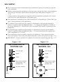
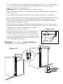
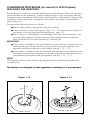
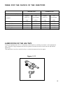
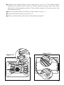
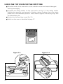
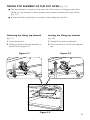
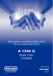
INSTALLATION and SERVICE INSTRUCTIONS
USE and CARE INSTRUCTIONS
A 726 G
DUAL FUEL COOKER
distributed by
DèLonghi
Pty Ltd
Dear Customer,
Thank you for having purchased and given your
preference to our product.
The safety precautions and recommendations reported
below are for your own safety and that of others. They
will also provide a means by which to make full use of
the features offered by your appliance.
Please keep this booklet in a safe place. It may be
useful in future, either to yourself or to others in the
event that doubts should arise relating to its operation.
This appliance must be used only for the task it has
explicitly been designed for, that is for cooking
foodstuffs. Any other form of usage is to be considered
as inappropriate and therefore dangerous.
The manufacturer declines all responsibility in the
event of damage caused by improper, incorrect or
illogical use of the appliance or be faulty installation.
Important:
This appliance is designed and manufactured solely for the cooking of domestic
(household) food and is not suitable for any non domestic application and therefore should not be used in a commercial environment.
The appliance guarantee will be void if the appliance is used within a non domestic environment i.e. a semi commercial, commercial or communal environment.
PRODUCT LABEL
2
FIRST TIME USE THE OVEN
It is advised to follow these instructions:
Clean the interior of the oven with cloth soaked in water and detergent
(neutral) then dry carefully.
■ Fit the wire racks as described at chapter “Use and care”.
■ Insert shelves and tray.
■ Switch on the empty oven on max to eliminate grease tracks from the heating
elements.
■
IMPORTANT PRECAUTIONS AND RECOMMENDATIONS FOR
USE OF ELECTRICAL APPLIANCES
Use of any electrical appliance implies the necessity to follow a series of fundamental
rules. In particular:
■ Never touch the appliance with wet hands or feet;
■
do not operate the appliance barefooted;
The appliance is not intended for use by young children or infirm persons
with supervision
■ Young children should be supervised to ensure they do not play with the
appliance
The manufacturer cannot be held responsible for any damages caused by improper,
incorrect or illogical use of the appliance.
■
3
IMPORTANT PRECAUTIONS AND RECOMMENDATIONS
After having unpacked the appliance, check to ensure that it is not damaged.
In case of doubt, do not use it and consult your supplier or a professionally qualified technician.
Packing elements (i.e. plastic bags, polystyrene foam, nails, packing straps, etc.) should not
be left around within easy reach of children, as these may cause serious injuries.
■
Do not attempt to modify the technical characteristics of the appliance as this
may become dangerous to use.
■
Do not carry out cleaning or maintenance operations on the appliance without
having previously disconnected it from the electric power supply.
■
After use, ensure that the knobs are in off position.
■
Do not allow children or other incapable people to use the appliance without
supervision.
■
During and after use of the cooker, certain parts will become very hot. Do not
touch hot parts.
■
Keep children away from the cooker when it is in use.
■
Some appliances are supplied with a protective film on steel and aluminium parts.
This film must be removed before using the appliance.
■
Fire risk! Do not store flammable material in the oven.
■
Make sure that electrical cables connecting other appliances in the proximity of
the cooker cannot come into contact with the hob or become entrapped in the
oven door.
■
Do not line the oven walls with aluminium foil. Do not place baking trays or the
drip tray on the base of the oven chamber.
■
The manufacturer declines all liability for injury to persons or damage to property
caused by incorrect or improper use of the appliance.
■
IMPORTANT NOTE: This appliance shall not be used as a space
heater, especially if installed in marine craft or caravans.
This cooker has been designed and constructed in accordance with the following
codes and specifications:
AGA101 (AS 4551) Approval Requirements for Domestic Gas cooking appliances
AS/NZS 3350-1
General Requirements for Domestic electrical appliances
AS/NSZ 3350-2-6
Particular Requirements for Domestic electrical cooking appliances
AS/NSZ 1044
Electromagnetic Compatibility Requirements.
4
1
INSTALLATION
CAUTION:
■
■
■
■
■
■
This appliance must be installed in accordance with these installation
instructions.
This appliance shall only be serviced by authorized personnel.
This appliance is to be installed only by an authorised person.
Incorrect installation, for which the manufacturer accepts no responsibility,
may cause personal injury of damage.
Always disconnect the cooker from mains power supply before carrying out
any maintenance operations or repairs.
In the room where the cooker is installed, there must be enough air to
allow the gas to burn correctly, according to the current local regulations.
ELECTRICAL REQUIREMENTS
The appliance must be connected to the mains checking that the voltage corresponds to the value given in the rating plate and that the electrical cable sections can withstand the load specified on the plate.
■ The appliance must be connected directly to the mains placing a two pole
switch with minimum opening between the contacts of 3 mm between the
appliance and the mains.
■ The power supply cable must not touch the hot parts and must be positioned so
that it does not exceed 50°C above ambient.
■ Once the appliance has been installed, the switch or socket must always be
accessible.
■ If the supply cord is damaged it must be replaced by the manufacturer or
it’s Service Agent or a similarly qualified person in order to avoid a hazard.
■
WARNING: This cooker must be connected to electrical supply using
V105 insulated cable.
N.B. The connection of the appliance to earth is mandatory.
If the installation requires alterations to the domestic electrical system call a qualified
electrician.
He should also check that the socket cable section is suitable for the power drawn by
the appliance.
5
CONNECTING THE FEEDER
CABLE
FEEDER CABLE SECTION
type “H05RR-F”
To connect the feeder cable to the cooker it is necessary to:
230 -240 V
■
Remove the 2 screws that hold
shield A behind the cooker.
■
Open completely the cable
clamp D.
■
Insert the feeder cable into the
cable save P. The supply cable
must be of a suitable size for the
current requirements of the appliance.
■
Connect the phase and earth
cables to terminal B.
■
Pull the feeder cable and block it
with the cable clamp D.
■
Re-mount shield A.
3 x 2,5 mm2 (**)
(**) – Connection with wall box connection.
Figure 1.1
230 V
L1 N PE
(L2)
N.B. The earth conductor must be
left about 3 cm longer than the
others.
Figure 1.2
B
A
D
P
6
CLEARANCES
Installation clearances and protection of combustible surfaces shall comply with
the current local regulations eg. AG 601 (AS 5601) Gas Installations code.
Installation shall comply with the dimension in Fig 1.3 bearing in mind that
Overhead Clearances
In no case shall the clearances between the highest part of the cooker be less than
600mm or for an overhead exhaust fan 750mm. AII other downward facing combustible surfaces less than 600mm above the cooker surface shall be protected for the
full width of the cooking surface in accordance with the standards noted above. In no
case shall the clearance be less than 450mm.
Rear and Side Clearances
Where the dimensions from the periphery of the nearest burner to any vertical combustible surface is less than 200mm the surface shall be protected in accordance with
the standards to a height of not less than 150mm above the cooking surface for the
full width or depth of the cooking surface
Where the dimensions from the periphery of the nearest burner to any horizontal combustible surface is less than 200 mm, the horizontal surface shall be greater than
10 mm below the surface of the hob, or the horizontal surface requirement above.
Protection of combustible surfaces.
The standards above specify that where required protection shall ensure that the surface temperature of the combustible surface does not exceed 65°C above room temperature.
If the cooker is located on a pedestal it is necessary to provide safety
measures to prevent falling out.
450 mm
650 mm
Figure 1.3
200 mm
500 mm
Cooker overall dimensions [mm]
• height: min 903 - max 908
• width: 700
• depth: 600
7
BACKGUARD
Before installing the cooker, assemble the backguard “C” (fig. 1.4).
■
Before assembling remove any protective film/adhesive tape.
■
Remove the two spacers “A” and the screw “B” from the rear of the cooktop.
■
Assemble the backguard as shown in figure 1.4 and fix it by screwing the central screw “B” and the spacers “A”.
Figure 1.4
B
A
8
C
MOVING THE COOKER
WARNING
When raising cooker to upright position always ensure two people carry out
this manoeuvre to prevent damage to the adjustable feet (fig. 1.5).
Figure 1.5
WARNING
Be carefull: do not lift the cooker
by the door handle when raising
to the upright position (fig. 1.6).
WARNING
When moving cooker to its final position DO NOT DRAG (fig. 1.7).
Lift feet clear of floor (fig. 1.5).
Figure 1.6
Figure 1.7
9
ADJUSTABLE FEET
■
Before installing the cooker level the appliance by screwing or unscrewing the
six adjustable feet fitted below.
Figure 1.8
WARNING!
For safety reasons unscrew
the feet (from screwed position) to the maximum extent
of 5 mm (fig. 1.8).
ANTI-TILT BRACKET
1. The anti-tilt bracket has to be attached as shown on figure below, it has to be fixed
on the floor and on the rear wall by no. 4 (four) suitable screws (not supplied).
2. After fixing the anti-tilt bracket, slide cooker into place. Be sure the rear right foot
slides under the anti-tilt bracket attached.
Figure 1.9
Dotted line showing the position
of the cooker when installed
ANTI-TILT BRACKET
FIXING
=
=
223
Foot of
cooker
10
Anti-tilt
bracket
GAS SUPPLY:
■
The connection must be executed by an authorised person according to the relevant standards.
■
Before connecting the appliance to the gas main, mount the brass conical adaptor
onto the gas inlet pipe, upon which the gasket has been placed (figures 1.10 1.11).
Conical adaptor and gasket are supplied with the appliance (packed with conversion kit for use with Natural gas or Propane gas).
■
This appliance is suitable for use with Natural Gas or Propane gas. (Check the “gas
type” sticker attached to the appliance).
■
For Natural Gas models the gas supply is connected to the pressure regulator
which is supplied with the appliance (fig. 1.11). Adjust the regulator to obtain a
test point pressure of 1 kPa with the two semi-rapid (SR) burners operating at the
maximum.
■
For Propane gas models the gas supply is connected to the test point adaptor
which is supplied with the appliance (fig. 1.10) and ensure that the supply pressure is regulated to 2.75 kPa.
■
The connection must be made at the rear of appliance. If the connection pipe
cross the cooker, it must be positioned under the cooker rear protection (fig. 1.12).
■
IMPORTANT: Use two spanners to tighten or loosen the connecting pipe (fig. 1.13)
Figure 1.10
Figure 1.11
Gas connection for
PROPANE GAS
Gas connection for
NATURAL GAS
Gas inlet pipe
Gas inlet pipe
Nipple
Nipple
Gasket
Gasket
Brass conical adaptor
(Thread tight: use
suitable seal)
Test
point
Brass conical adaptor
(Thread tight: use
suitable seal)
Test point adaptor
Gas regulator
Test
point
11
1. After connecting the gas supply, check the piping and connections for leaks using
a soap and water solution. The presence of bubbles indicates a leak, tighten or
replace connections as appropriate.
Warning: Do not use any naked flame to check for leaks.
2. Adjust the test point pressure or supply pressure to the value which is appropriate
for the gas type.
3. The operation of the appliance must be tested when installation is completed.
4. Turn on the appliance gas controls and light each burner individually and in combination. Check for a well defined blue flame without any yellow tipping. If any
abnormality is evident then check that the burner cap is located properly and the
injector nipple is aligned correctly.
5. Check the minimum burner setting by quickly rotating the gas control knob from
the maximum to the minimum position, the flame must not go out. If adjustment is
required carry out the “minimum burner setting
adjustment" procedure described
Figure 1.13
6. If satisfacfory performance cannot be obtained, the
installer shall check the installation and notify the
local gas supply authority for a gas supply problem,
or if it is an appliance problem, our Customer Service
Centre should be called to obtain the nearest authorized DeLonghi Service Agent.
WARNING, This appliance IS NOT SUITABLE for
installation with a hose assembly.
Figure 1.12
cooker
rear protection
gas pipe
12
CONVERSION PROCEDURE (to convert to LPG Propane)
REPLACING THE INJECTORS
This appliance is suitable for use with Natural gas or Propane gas (check the “gas type”
sticker attached to the appliance). A label stating the type of gas used after replacing
the injectors must be attached at the rear of the appliance, in proximity of the gas inlet
connection. The nominal gas consumption and injector size details are provided in
table at page 15.
To replace the injectors proceed as follows:
■ Remove pan supports and burners from the cooktop.
■ Using a spanner, remove the injector J (fig. 1.14 - 1.15) and replace it with one
according to the gas type (see following tables - page 15).
■ Affix to the rear of the appliance, in proximity of the gas inlet connections, the
warning label (supplied with the conversion kit) stating that the cooker has
been converted for use with Propane gas / Natural gas.
IMPORTANT
■ If the cooker is suitable for use with Natural gas and must be converted for use
with Propane gas, before connecting to gas main remove the appliance gas
regulator and replace with test point adaptor (see fig. 1.10 - 1.11)
■ If the cooker is suitable for use with Propane gas and must be converted for use
with Natural gas, before connecting to the gas main remove the appliance test
point adaptor and replace with gas regulator (see figs. 1.10 - 1.11).
NOTE:
Gas regulator and test point adaptor are supplied with the appliance (packed with
conversion kit)
The burners are designed so that regulation of primary air is not required.
Figure 1.14
Figure 1.15
J
J
13
MINIMUM BURNER SETTING ADJUSTMENT
Check whether the flame spreads to all burner ports when the burner is lit with the gas
tap set to the minimum position. If some ports do not light, increase the minimum gas
rate setting.
Check whether the burner remains lit even when the gas tap is turned quickly from
the maximum to the minimum position. If the burner does not remain lit, increase the
minimum gas rate setting.
The procedure for adjusting the minimum gas rate setting is described below.
Turn on the burner
■ Turn the tap to the MINIMUM position
■ Take off the knob
■ With a small flat screwdriver turn the screw “F” (fig. 1.16) to the correct regulation.
■
Normally for Propane gas, the regulation screw is tightened up.
Figure 1.16
F
14
TABLE FOR THE CHOICE OF THE INJECTORS
Natural gas
1.0
Test Point Pressure [kPa]
BURNER
Propane gas
2.75
Injector
Orifice Dia.
Gas
Consumption
Injector
Orifice Dia.
Gas
Consumption
[mm]
[MJ/h]
[mm]
[MJ/h]
Auxiliary (A)
0.85
3.60
0.53
3.60
Semi-rapid (SR)
1.12
6.30
0.70
6.30
Rapid (R)
1.45
10.60
0.91
10.60
Triple ring (TC)
1.65
13.30
0.95
11.90
LUBRICATION OF THE GAS TAPS
If the gas tap becomes stiff, it is necessary to dismantle it carefully and clean it with petroleum
spirit. Specialist high temperature resistant grease should be used to lubricate the tap before
replacing.
The operations must be carried out by an authorised person/service agent.
Figure 1.17
15
12
USE and CARE
CAUTION:
■
This appliance must be used only for the task it has explicitly been designed for,
that is for domestic cooking of foodstuffs. Any other form of usage is to be considered as inappropriate and therefore dangerous.
■
Do NOT place combustible materials or products on this appliance at any time.
■
Do NOT spray aerosols in the vicinity of this appliance while it is in use.
Please note: This appliance incorporates a safety cooling fan which you will hear
operating whenever the oven or grill are in use. This fan is to reduce the external
temperature of the appliance and cool the internal components.
16
GREASE FILTER (BOTTOM MAIN OVEN ONLY)
A special screen is provided at the back of the multifunction main oven to catch
grease particles, mainly when meat is being roasted (fig. 2.1).
■ When baking pastry etc. this filter should be removed.
■
■
Always clean the filter after cooking as any solid residues on it might adversely
affect the oven performance.
Figure 2.1
17
USING THE BOTTOM MAIN OVEN FOR THE FIRST TIME
Slide off the sliding shelves to the oven wall by unscrewing the 2 screws as in Fig.
2.3. The grill is secured to the rear wall of the oven on a hinge system that allows
it to be lowered to allow proper access when cleaning the oven ceiling (fig. 2.2).
■ Clean the inside of the oven with a cloth soaked in water and neutral detergent
and dry thoroughly.
■
Figure 2.2
18
Assemble the sliding shelves on the oven wall as in Fig. 2.3. The sliding shelves
facilitate the insertion and removal of shelves during cooking; they stop when
pulled out to the maximum position. These shelves support all accessory trays and
are dishwasher safe.
■ Slide in the grease filter on the back of the oven as in Fig. 2.1.
■
■
Position the shelf and tray as per Fig. 2.4.
■
Switch on the bottom main oven as described at page 30.
Figure 2.4
Figure 2.3
19
USING THE TOP OVEN FOR THE FIRST TIME
Clean the inside of the oven with a cloth soaked in water and neutral detergent
and dry thoroughly.
■ Assemble the sliding shelves on the oven wall as in Fig. 2.5. The sliding shelves
facilitate the insertion and removal of shelves during cooking; they stop when
pulled out to the maximum position. These shelves support all accessory trays and
are dishwasher safe.
■ Position the shelf and tray as per Fig. 2.6.
■
■
Switch on the oven as described at page 27.
Figure 2.5
20
Figure 2.6
TILTING TOP ELEMENT OF THE TOP OVEN
■
■
(fig. 2.9)
The top element is secured to the rear wall of the oven on a hinge system that
allows it to be lowered to allow proper access when cleaning the oven ceiling
(fig. 2.9).
In the front the top element is secured to the ceiling by a hook A.
Unlocking the tilting top element
Locking the tilting top element
(fig. 2.7)
(fig. 2.8)
1. Open the hook A.
2. Gently pull down the top element as
shown in the figure 2.9.
1. Gently lift up the top element.
2. Close the hook A on the top element
bar.
Figure 2.7
Figure 2.8
A
2
A
1
1
2
A
Figure 2.9
21
CONTROL PANEL
Figure 2.10
10
11
MAIN OVEN
TOP OVEN
A
9
8
7
6
5
4
CONTROL PANEL - Controls description
1. Front right rapid burner control knob (3)
2. Rear right semi-rapid burner control knob (2)
3. Central triple-ring burner control knob (4)
4. Rear left semi-rapid burner control knob (2)
5. Front left auxiliary burner control knob (1)
6. Conventional oven switch/thermostat knob (top oven)
7. Multifunction oven thermostat knob (bottom main oven)
8. Multifunction oven switch knob (bottom main oven)
9. Electronic programmer (bottom main oven only)
10. Indicator light (bottom oven)
11. Indicator light (top oven)
22
3
2
1
13
GAS HOB
Figure 3.1
2
2
4
1
GAS BURNERS
1.
2.
3.
4.
Auxiliary burner (A)
Semi-rapid burner (SR)
Rapid burner (R)
Triple ring burner (TC)
3
Natural Gas
MJ/h
Propane gas
MJ/h
3.6
6.3
10.6
13.3
3.6
6.3
10.6
11.9
Note:
The electric ignition is incorporated in the knobs.
The appliance has a safety valve system fitted, the flow of gas will be stopped if and
when the flame should accidentally go out.
23
LIGHTING GAS BURNERS
FITTED WITH SAFETY VALVE DEVICE AND ELECTRONIC IGNITION
Figure 3.2
■
Check that the electricity is
switched on to allow spark ignition.
■
Make sure that all controls are
turned to zero.
■
The gas flow to the burner is
controlled by taps with safety
cutout device. If the burner
flame should go out, the safety
cut-off valve will automatically
stop the gas flow. The switch for
the electric ignition is incorporated in the knobs.
■
You control the flow by turning the knob indicator to line up with the following
symbols:
– Symbol
24
●
: tap closed (burner off)
– Symbol
: High (maximum)
– Symbol
: Low (minimum)
■
To ignite automatically, push the required knob down and turn it to maximum,
keeping the knob down until the burner lights. When the flame is lit, wait for
about ten second with the knob down (safety cut-off activation delay).
■
You can control the temperature by the knob to “High” from “minimum”.
■
To switch off, turn the knob clockwise until you hear the safety click.
■
Note that, if you are using a burner at the minimum setting, you turn the knob
clockwise past the maximum setting before reaching the off position.
■
Whenever the lighting of the burners is difficult due to peculiar conditions of
the gas features or supply, it is advised to repeat the ignition with the knob on
“minimum” position.
■
If when lighting any of the burners an abnormal flame appears, switch the
burner off and relight using the minimum setting.
■
If the flame is still not correct, turn the burner off and call our Customer Service
center for your nearest Authorized DeLonghi Service Agent.
■
In the case of a mains failure light the burner with a match or lighted taper.
CHOICE OF BURNER
The burner must be chosen according to the diameter of the pans and energy
required.
For optimum efficiency use a wok or pan no smaller than 230mm diameter.
Figure 3.3
do not use pans with concave or convex bases
Burners
Pan diameter
Auxiliary
Semi-rapid
Rapid
Triple ring
Wok
12 - 14 cm
16 - 24 cm
24 - 26 cm
26 - 28 cm
max 36 cm
Saucepans with handles which are excessively heavy, in relationship to the weight
of the pan, are safer as they are less likely to tip.
Pans which are positioned centrally on burners are more stable than those which
are offset.
It is far safer to position the pan handles in such a way that they cannot be
accidentally knocked.
When deep fat frying fill the pan only one third full of oil.
DO NOT cover the pan with a lid and DO NOT leave the pan unattended.
In the unfortunate event of a fire, leave the pan where it is and turn off all
controls.
Place a damp cloth or correct fitting lid over the pan to smother the flames.
DO NOT use water on the fire.
Leave the pan to cool for at least 30 minutes.
25
CORRECT USE OF TRIPLE-RING BURNER
■
The flat-bottomed pans are to be placed directly onto the pan-support.
■
To use the WOK, you must place the wok stand in the CORRECT position as
shown in Fig. 3.4 - 3.5.
IMPORTANT:
The special grille for wok pans (fig. 3.5) MUST BE PLACED ONLY over the pan-rest for
the triple-ring burner.
26
Figure 3.4
Figure 3.5
WRONG
CORRECT
41
CONVECTIONAL OVEN
(Top oven)
NOTE:
Upon first use, it is advisable to operate
the oven at the maximum temperature
(knob on MAX position) for 60 minutes
to eliminate any traces of grease from
the electrical resistance.
WARNING:
The door is hot use the handle.
GENERAL FEATURES
OPERATING PRINCIPLES
The convection oven is equipped with 2
electrical heating elements (upper and
lower) for normal oven cooking.
Heating and cooking in this oven are
obtained by normal convection. The
heat is produced by the upper and
lower heating elements.
The input of the elements is:
– Upper element,
700 W
– Lower element,
1000 W
Attention: the oven door becomes
very hot during operation.
Keep children away.
125
MAX 250
100
75
Figure 4.1
22
5
27
0
200
175
15
SWITCH and TEMPERATURE SELECTOR KNOB (Fig. 4.1)
Rotate the knob clockwise to set the oven for one of the following functions:
OFF. As per fig. 4.1
By setting the knob to this position, only the oven light comes on (15 W).
The light remains on whilst any of the cooking temperature are selected.
50
to
250
MAX
The upper and lower heating elements are switched on.
The oven temperature can be set between 50° C and MAX position.
It is necessary to preheat the oven before introducing the foods to be cooked.
The set temperature has been reached when the temperature indicator light
goes off.
COOKING ADVICE
STERILIZATION
Sterilization of foods to be preserved, in full and hermetically sealed jars, is done in the
following way:
a. Set the thermostat knob to position 185 °C and preheat the oven.
b. Fill the dripping pan with hot water.
c. Set the jars onto the dripping pan making sure they do not touch each other and
the door and set the thermostat knob to position 135 °C.
When sterilization has begun, that is, when the contents of the jars start to bubble,
turn off the oven and let cool. Check your recycle book for full instructions.
28
REGENERATION
Set the switch/thermostat knob to position 150° C.
Bread becomes fragrant again if wet with a few drops of water and put into the oven
for about 10 minutes at the highest temperature.
ROASTING
To obtain classical roasting, it is necessary to remember:
– that it is advisable to maintain a temperature between 180° and 200 °C.
– that the cooking time depends on the quantity and the type of foods.
OVEN COOKING
Before introducing the food, preheat the oven to the desired temperature.
For a correct preheating operation, it is advisable to remove the tray from the oven
and introduce it together with the food, when the oven has reached the desired temperature.
See Cooking Chart at page 41 for recommended cooking temperature.
Check the cooking time and turn off the oven 5 minutes before the theoretical time to
recuperate the stored heat.
29
51
MULTIFUNCTION OVEN (Bottom main oven)
NOTE:
To eliminate traces of grease in manufacture it is necessary to pre-heat the
oven at the maximum temperature.
• For 60 minutes in the
position,
for 30 minutes in the
position,
and for another 15 minutes in the
position.
GENERAL FEATURES
As its name indicates, this is an oven that
presents particular features from an operational point of view.
In fact, it is possible to insert 7 different
programs to satisfy every cooking need.
The 7 positions, thermostatically controlled, are obtained by 4 heating elements which are:
– Bottom element
– Top element
– Grill element
– Circular element
1300 W
1000 W
2000 W
2200 W
IMPORTANT
To open the bottom left door operate as
indicated in fig. 5.1
Figure 5.1
30
WARNING:
The door is hot, use the handle.
OPERATING PRINCIPLES
Heating and cooking in the MULTIFUNCTION oven are obtained in the following ways:
a. by normal convection
The heat is produced by the upper
and lower heating elements.
b. by forced convection
The fan draws in air contained within
the oven housing at the rear of the
oven and forces it over the circular
heating element. The hot air envelops
the food in the oven giving faster and
more even cooking before it is drawn
back into the housing to repeat the
cycle. It is possible to cook several
dishes simultaneously due to the even
distribution of heat within the oven.
c. by forced semi-convection
The heat produced by the top and
bottom heating elements is distributed throughout the oven by the fan.
d. by radiant heat
The food is grilled by the infra red grill
element.
e. by radiant heat and ventilation
The food is grilled by the grill element
is distributed throughout the oven
f. by ventilation
The food is defrosted by using the fan
only function without heat.
Figure 5.3
75
50
Figure 5.2
100
250
200
1
25
225
175
150
THERMOSTAT
(Fig. 5.2)
This only sets the cooking temperature and does not switch the oven on.
Rotate clockwise until the required temperature is reached (from 50 to 250°C).
The elements will turn ON or OFF automatically according to the energy need which is
determined by the thermostat.
FUNCTION SELECTOR KNOB
(Fig. 5.3)
Rotate the knob clockwise to set the oven for one of the following functions:
OVEN LIGHT
By setting the knob to this position, only the oven light comes on (15 W).
The light remains on whilst any of the cooking temperature are selected.
TRADITIONAL CONVECTION COOKING
The upper and lower heating elements are switched on. The heat is diffused by
natural convection and the temperature must be set between 50° C and 250° C.
It is necessary to preheat the oven before adding the foods to be cooked.
Recommended for:
For foods which require the same cooking temperature both internally and externally,
i. e. roasts, spare ribs, meringue, etc.
31
GRILLING
The infra-red heating element is switched on. The heat is diffused by radiation.
Use with the oven door closed and the thermostat knob to between 50° and 225°C.
Note: It is recommended that you do not grill for longer than 30 minutes at
any one time.
Attention: the oven door becomes very hot during operation. Keep children
away.
For correct use see “USE OF THE GRILL”
Recommended for:
Intense grilling action for cooking with a broiler; browning, crisping, “au gratin”, toasting,
etc.
DEFROSTING FROZEN FOODS
Only the oven fan is on. To be used with the temperature knob on “●” because the other
positions will have no effect. The defrosting is done by simple ventilation without heat.
Recommended for:
To rapidly defrost frozen foods; 1 kilogram requires about one hour.
The defrosting times vary according to the quantity and type of foods to be defrosted.
HOT AIR COOKING
The circular element and the fan are on. The heat is diffused by forced convection
and the temperature must be set between 50° and 250 °C.
It is not necessary to preheat the oven.
Recommended for:
For foods that must be well done on the outside and tender or rare on the inside,
i. e. lasagna, lamb, roast beef, whole fish, etc.
32
VENTILATED GRILL COOKING
The infra-red ray grill and the fan are on.
The heat is mainly diffused by radiation and the fan then distributes it throughout the oven.
The temperature must be regulated between 50° and 200°C maximum with the thermostat knob. It is necessary to preheat the oven for about 5 minutes.
Use with the oven door closed.
Note: It is recommended that you do not grill for longer than 30 minutes at
any one time.
Attention: the oven door becomes very hot during operation.
Keep children away.
For correct use see “GRILLING AND “AU GRATIN”.
Recommended for:
For grill cooking when a fast outside browning is necessary to keep the juices in, i. e. veal
steak, steak, hamburger, etc.
THAWING AND WARMING UP
The upper element and the circular element connected in series, are switched on; also the
fan is on. The heat is diffused by forced convection with the most heat being produced by
the upper element.
The temperature must be set between 50° and 140 °C.
Recommended for:
To keep foods hot after cooking. To slowly heat already cooked foods.
CONVECTION COOKING WITH VENTILATION
The upper and lower heating elements and the fan turn on.
The heat coming from the top and bottom is diffused by forced convection.
The temperature must be set between 50° and 250 °C.
Recommended for:
For foods of large volume and quantity which require the same internal and external
degree of cooking; for ie: rolled roasts, turkey, legs, cakes, etc.
33
COOKING ADVICE
STERILIZATION
Sterilization of foods to be preserved, in full and hermetically sealed jars, is done in the
following way:
a. Set the switch to position
.
b. Set the thermostat knob to position 185 °C and preheat the oven.
c. Fill the dripping pan with hot water.
d. Set the jars onto the dripping pan making sure they do not touch each other and
the door and set the thermostat knob to position 135 °C.
When sterilization has begun, that is, when the contents of the jars start to bubble,
turn off the oven and let cool.
Check your recycle book for full instructions.
REGENERATION
Set the switch to position
and the thermostat knob to position 150° C.
Bread becomes fragrant again if wet with a few drops of water and put into the oven
for about 10 minutes at the highest temperature.
ROASTING
To obtain classical roasting, it is necessary to remember:
– that it is advisable to maintain a temperature between 180° and 200 °C.
– that the cooking time depends on the quantity and the type of foods.
SIMULTANEOUS COOKING OF DIFFERENT FOODS
The MULTI-FUNCTION oven set on position
gives simultaneous cooking of
and
different foods.
Different foods such as fish, cake and meat can be cooked together without mixing the
smells and flavours.
This is possible since the fats and vapours are oxidized while passing through the electrical
element and therefore are not deposited onto the foods.
The only precautions to follow are:
– The cooking temperatures of the different foods must be as close to as possible, with a
maximum difference of 20° - 25 °C.
– The introduction of the different dishes in the oven must be done at different times in
relation to the cooking times of each one.
This type of cooking saves time and energy.
34
GRILLING AND “AU GRATIN”
As the hot air completely covers the food to be cooked, grilling may be done with
the food on rack in the oven. The knob should be switched to position
.
Set the thermostat knob between 50°C and 200°C maximum and after having preheated the oven, simply place the food on the grid.
Close the door and let the oven operate until grilling is done.
Adding a few dabs of butter before the end of the cooking time gives the golden “au
gratin” effect.
Grilling with the oven door closed.
It is recommended that you do not grill for longer than 30 minutes at any
one time.
ATTENTION: the oven door becomes very hot during operation.
Keep children away.
USE OF THE GRILL
Set the function selector knob to position
and the thermostat knob between 50°C and
225°C maximum.
Leave to warm up for approximately 5 minutes with the door closed.
Introduce the food to be cooked, positioning the grill pan as close to the grill as possible.
Insert the drip pan under the rack to collect the cooking juices.
Always grill with the oven door closed.
Grilling with the oven door closed and do not for longer than 30 minutes at any
one time.
Attention: the oven door becomes very hot during operation.
Keep children away.
OVEN COOKING
Before introducing the food, preheat the oven to the desired temperature.
For a correct preheating operation, it is advisable to remove the tray from the oven
and introduce it together with the food, when the oven has reached the desired temperature.
See Cooking Chart at page 41 for recommended cooking temperature.
Check the cooking time and turn off the oven 5 minutes before the theoretical time to
recuperate the stored heat.
35
ELECTRONIC PROGRAMMER
(Bottom main oven only)
The electronic programmer is a device which groups together the following functions:
■ 24 hours clock with illuminated display
■ Timer (up to 23 hours and 59 minutes)
■ Program for automatic oven cooking
■ Program for semi-automatic oven cooking
Description of the buttons:
Timer
Cooking time
End of cooking time
simultaneously: Switching to manual and program reset
Minus function to decrease the number shown on the display or to change the
buzzer frequency
Plus function to increase the number shown on the display
Description of the illuminated symbols:
A flashing: Programmer in automatic position but not programmed
A always illuminated: Programmer in automatic position with program inserted.
Automatic cooking taking place
Timer in operation
and A flashing: Program error.
(The time of day lies between the calculated cooking start and end time).
Note:
Select a function by pressing the respective button and, in 5 seconds, set the required
time with the
/
buttons (“one-hand” operation).
A power cut makes the clock go to zero and cancels the set programs.
Figure 5.4
A
36
SETTING TIME OF DAY
(fig. 5.5)
The programmer is provided with an electronic clock
with luminous figures showing the hour and minutes.
The first time the oven is connected up to the electricity supply and after a power cut, three zeroes will flash
on the programmer display. To adjust the time, the
two buttons
must be pressed simultaneously
and then the button
or
until the correct time is
set. Setting speed automatically increases if you keep
the setting buttons pressed.
Figure 5.5
MANUAL OPERATION
Figure 5.6
To use the oven manually, i.e. without the programmer, you must cancel the flashing A by pressing the
two buttons
simultaneously (the letter A will go
out and the symbol
will come on).
CANCELLING A PROGRAMME
If the letter A is not flashing (which means that a
cooking program has already been set) by pressing the
two buttons
simultaneously you will cancel the
program and switch to manual.
If the oven is on, you must switch it off manually.
37
MINUTE MINDER
Figure 5.7
The minute counter function consists simply of an
acoustic signal which can be set for a maximum of 23
hours 59 minutes. If the letter A is flashing, press the
two buttons
simultaneously.
To set the time, press button
and then button
or
until the required time appears on the display
(Fig. 5.7). The symbol
will come on.
Countdown will begin immediately and can be seen
on the display at any time by simply pressing button
.
When the time expires, the symbol
will go out and
an intermittent acoustic signal will come on which can
be switched off by pressing any of the buttons.
AUDIBLE SIGNAL
The audible signal sounds at the end of a minute minder cycle or of a cooking programme for a period of 7
minute.
The signal can be cancelled by pressing any function
button.
Pressing the
button without having previously
selected a function the frequency of the signal
change. You can choose from three variations.
The selected signal is audible as long as the
button
is pressed.
38
Figure 5.8
SEMI-AUTOMATIC COOKING
This automatically switches the oven off after the required
cooking time. There are two methods of semi-automatic
cooking:
1° METHOD: Programming the cooking time
Figure 5.9
A
(Fig. 5.9)
– Set the cooking time by pressing button
and then
button
to move forward or
to move back if you
have gone beyond the required time.
The letter A and the symbol
will appear.
2° METHOD: Programming the end of cooking
time (Fig. 5.10)
– Set the end of cooking time by pressing button
then button
to move forward or
to move
back if you have gone beyond the required time.
The letter A and the symbol
will appear.
and
Figure 5.10
A
Having programmed according to one of the above
methods, set the temperature and function via the function selector and thermostat knob (see specific chapters).
The oven will come on immediately and when the set
time or programmed end of cooking time expires, it will
automatically switch off.
During cooking the letter A and the symbol
remains
on; press button
to display the remaining time until
end of cooking or press button
to display the end of
cooking time.
The cooking program can be cancelled at any time by
pressing the two buttons
simultaneously.
At the end of cooking, the oven switch off, the symbol
go out, the letter A flash and the acoustic signal come
on - this can be switched off by pressing any of the buttons.
Reset the function selector and thermostat knob and set
the programmer to manual by pressing the two buttons
simultaneously.
39
AUTOMATIC COOKING
To cook in the oven in automatic mode follow the instructions below:
1. Set the cooking time
2. Set the end of cooking time
3. Set the cooking temperature and function
These operations are carried out as follows:
1. Set the cooking time by pressing button
and then
to move forward or
to move back if you have
gone beyond the required time (fig. 5.11).
The letter A and the symbol
appear.
2. Press button ; the cooking time already added to the
clock time appear.
Set the end of cooking time by pressing button
; if
you go beyond the required time, you can go back by
pressing button .
The symbol
go out and the letter A remains on
(fig. 5.12). If during the setting the letter A begins to
flash on the display and the acoustic signal comes on,
this indicates a programming error, i.e. the cooking
cycle has been superimposed on the clock time. In this
case alter the end of cooking time or the cooking time
as above.
3. Set the cooking temperature and function via the function selector and thermostat knob (see specific chapters). The oven is now programmed and everything
will work automatically; the oven will come on as
required and finish cooking at the programmed time.
At the start of the cooking the symbol
appear.
During cooking the letter A and the symbol
remains
on; press button
to display the remaining time until
end of cooking or press button
to display the end of
cooking time.
The cooking program can be cancelled at any time by
pressing the two buttons
simultaneously.
At the end of cooking, the oven switch off, the symbol
go out, the letter A flash and the acoustic signal come
on - this can be switched off by pressing any of the buttons.
Reset the function selector and thermostat knob and set
the programmer to manual by pressing the two buttons
simultaneously.
Caution: If the electricity supply is cut off (the display numbers will flash), the clock will reset and all
the programs entered will be cancelled.
40
Figure 5.11
A
Figure 5.12
A
16
Cooking chart
RECOMMENDED COOKING TEMPERATURE
Food
°C
°F
Gas
Mark
Shelf
Position*
Cooking
Time (approx)
CAKES
Victoria sandwich
Small cakes/buns
Maidera cake
Fruit cake
Rich fruit cake
Scones
190
190
180
170
150
225
375
375
350
325
300
425
5
5
4
3
2
8-9
2 or 3
1 and 2
2 or 3
3
3 or 4
2
20-25 mins
15-20 mins
20 mins
13/4 hours
21/2 hours
8-10 mins
PASTRY
Puff
Short crust
Plate tarts
Quiches and flans
225
200
200-210
200-210
425
400
400-410
400-410
8-9
6
6
6
2
2
1 or 2
1 or 2
10-20 mins
20-30 mins
30-35 mins
40-45 mins
225
220
230
425
425
450
7-8
7
8
2
1 or 2
2
35-55 mins
15-20 mins
20 mins
190
190
190-200
190
190
180
150-170
375
375
375-400
375
375
350
300-325
5
5
5-7
5
5
4
2-3
2 or 3
2 or 3
2 or 3
2 or 3
2 or 3
2 or 3
2 or 3
20 mins/lb + 20 mins
25-30 mins/b + 25 mins
30 mins/lb + 30 mins
30 mins/b + 30 mins
30 mins/b + 30 mins
18-20 mins/b + 20 mins
11/2 2 hours
YEAST
Bread loaf
Bread rolls
Pizza dough
ROAST MEAT
Beef – Medium
Lamb
Pork
Veal
Chicken
Turkey up to 10lb
Stews/casseroles
N.B. For fan function reduce the temperature by 10-20°C. For any dish taking one
hour or over to cook, reduce the cooking
time by 10 minutes per hour.
* Shelf positions have been counted from
the top of the oven to the base.
A fan oven creates more even temperature
throughout, therefore the shelf positions are
not as critical.
41
71
Maintenance
Period
Daily
Monthly
3 - 4 Yearly
Cleaning and Maintenance
Description
• Clean gas cooktop as per instructions below
• Remove burner caps, burner rings & base and clean using
non abrasive detergent & rinse in cold water & dry thoroughly
before replacing back on hob
• Clean ignitor tip & thermocouple using damp soapy cloth
and dry thoroughly
• Contact your local authorized gas Service Agent to perform
a thorough check on all gas components on the gas cooker
GENERAL ADVICE
■
■
■
■
■
Before you begin cleaning, you must ensure that the appliance is
switched off.
It is advisable to clean when the appliance is cold and especially when
cleaning the enamelled parts.
Avoid leaving alkaline or acidic substances (lemon juice, vinegar, etc.) on the
surfaces.
Avoid using cleaning products with a chlorine or acidic base.
Do not use a steam cleaner because the moisture can get into the
appliance thus make it unsafe.
ENAMELLED PARTS
■
■
All of the enamelled parts must be washed only with a sponge and soapy
water or with non-abrasive products.
Dry, preferably, with chamois.
STAINLESS STEEL SURFACES (COATED)
■
■
42
The stainless steel front panels on this cooker (facia and oven doors) are
protected by a finger-print proof lacquer. To avoid damaging this lacquer, do
not clean the stainless steel with abrasive cleaners or abrasive cloths or
scouring pads.
ONLY SOAP/WARM WATER MUST BE USED TO CLEAN THE STAINLESS
STEEL SURFACES.
STAINLESS STEEL SURFACES (UNCOATED)
■
■
The hob + sides are made from un-coated stainless steel.
Can be cleaned with an appropriate stainless steel cleaner.
OVENS
■
■
The ovens with smooth enamel must be cleaned after every use, using
suitable products. Please note that after using the oven for 30 minutes on the
highest temperature eliminates most grime reducing it to ashes.
Do not use abrasive substances to clean the oven.
GAS TAPS
■
If the gas taps are not working properly, call our Customer Service Centre to
obtain the nearest Authorized De Longhi Service Agent.
GREASE FILTER (BOTTOM MAIN OVEN ONLY)
■
■
Clean the filter after any cooking! The grease filter can be removed for
cleaning and should be washed regularly in hot soapy water (see page 17).
Always dry the filter properly before fitting it back into the oven.
GRILL HEATING ELEMENT
■
The heating element is self-cleaning and does not require maintenance.
43
BURNERS
They can be removed and washed only with soapy water. Detergents can be used but must
not be abrasive or corrosive.
Do not use abrasive sponges or pads.
Do not put in dishwasher.
After each cleaning, make sure that the burner-caps, as well as the burners, have
been well wiped off and CORRECTLY POSITIONED.
It is essential to check that the burner flame distributor F and the cap C has been
correctly positioned (see fig. 7.1- 7.2) - failure to do so can cause serious problems.
Check that the electrode S (fig. 7.1) is always clean to ensure trouble-free sparking.
Check that the probe T (fig. 7.1) next to each burner is always clean to ensure correct
operation of the safety valves. Both the probe and ignition plug must be very carefully
cleaned.
Note:
The electrode S must be very carefully cleaned. To avoid damage to the
electric ignition do not use it when the burners are not in place.
Figure 7.1
Figure 7.2
C
F
S
T
44
TRIPLE RING BURNER
The triple ring burner must be correctly positioned (see fig. 7.5); the burner rib must be
located in position as shown by the arrow fig. 7.3).
The burner correctly positioned must not rotate (fig. 7.4).
Then position the cap A and the ring B (fig. 7.4 - 7.5).
Figure 7.3
Figure 7.5
Figure 7.4
A
B
45
REPLACING THE OVEN LIGHT
■
Before any maintenance is started involving electrical parts of the
appliance, it must be disconnected from the power supply.
■
Let the oven cavity and the heating elements cool down;
■
Switch off the electrical supply;
■
Unscrew the protective cover (fig. 7.6);
■
Unscrew and replace the bulb with a new one suitable for high temperatures
(300°C) having the following specifications: 230-240V 50 Hz, 15W, E14
■
Refit the protective cover
Note: Oven bulb replacement is not covered by your guarantee.
Figure 7.6
2
46
1
REMOVING THE BOTTOM OVEN DOOR
The oven door can easily be removed as follows:
■
Open the door.
■
Unscrew the 4 screws of the bottom hinge (fig. 7.7)
■
Hold the door and unscrew the 3 screws of the upper hinge (fig. 7.8).
■
Remove the door following the arrow C (fig. 7.7 - 7.8)
■
Rest the door on a soft surface.
■
To replace the door, repeat the above steps in reverse order.
Figure 7.8
Figure 7.7
c
c
47
REMOVING THE TOP OVEN
DOOR
Figure 7.9a
The oven doors can easily be removed as
follows:
■
Open the door to the full extent
(fig. 7.9a).
■
Open the lever “A” completely on
the left and right hinges (fig. 7.9b).
■
Hold the door as shown in
fig. 7.9.
■
Gently close the door (fig. 7.9)
until left and right hinge levers “A”
are hooked to part “B” of the door
(fig. 7.9b)
Figure 7.9b
A
■
Withdraw the hinge hooks from
their location following arrow “C”
(fig. 7.9d).
■
Rest the door on a soft surface.
■
To replace the door, repeat the
above steps in reverse order.
B
Figure 7.9c
Figure 7.9
Figure 7.9d
C
48
Service and Maintenance
If the ignition spark fails to ignite or does not light the gas, check the following
items before calling our Customer Service Centre to obtain the nearest Authorised
Service Agent:
■
■
■
Burner is reassembled and located correctly.
Spark electrode and white ceramic are clean and dry.
240 VAC power supply is connected.
Contact the local gas utility or our Customer Service Centre to obtain the nearest
Authorized Service Agent.
■
■
■
You can smell gas when all burners are turned on.
The burners do not remain alight at the minimum marked setting.
The burner flame is yellow or emits an unusual odour.
Note that a bi-annual inspection of the appliance by an authorized service agent
or your locate gas utility will ensure many years of trouble free operation of your
appliance.
49
WIRING DIAGRAM
PR
S2
S1
F1
1
1a
F2
E1
N/7
L/8
1a
2a
1
2
P3
3a
3
P1
4a
4
5a
5
6a
6
7a
7
8a
9
10a
10
11a
11
3
4
P2
8
9a
1
2
E2
*
A
Lf1
LF
C1
PA
S1
C
CIR
G
V
TL1
CF
S
TL3
TL2
T
1131533
Bottom main oven switch diagram
1 2 3 4 5
POSITION 0
M
6
7
8
9
L
N
10 11
1a 2a 3a 4a 5a 6a 7a 8a 9a 10a 11a
FUNCTION
1
40° )
Oven light
FUNCTION
2
80° )
Traditional convection cooking
FUNCTION
3
120° )
Grilling
FUNCTION
4
160° )
Defrosting frozen foods
FUNCTION
5
Hot air cooking
FUNCTION
6
Top oven switch diagram
1
200° )
7
280° )
8
320° )
Maintaining temperature after
cooking or slowly heating foods
FUNCTION
Convection cooking with ventilation
50
3
4
POSITION 0
240° )
P3
Ventilated grill cooking
FUNCTION
2
FUNCTION
1
30° )
Oven light
FUNCTION
2
50°-250° )
Traditional convection cooking
P1
P2
ELECTRIC DIAGRAM KEY
TOP
F2
E2
S2
Lf1
C1
S1
TL1
OVEN
Oven switch
Oven thermostat
Thermostat pilot lamp
Oven lamp
Top element
Bottom element
Thermal overload
BOTTOM OVEN
F1
Oven switch
E1
Oven thermostat
S1
Thermostat pilot lamp
PR
Oven programmer 1P
LF
Oven lamp
C
Top element
G
Grill element
V
Fan
S
Bottom element
CIR Circular element
TL2 Thermal overload
CF
TL3
M
T
Cooling fan
Thermal overload
Terminal block
Earth connection
Descriptions and illustrations in this booklet are given as simply indicative. The manufacturer reserves the right,
considering the characteristics of the models described here, at any time and without notice, to make eventual
necessary modifications for their construction or for commercial needs.
51
cod. 1102577 - ß2