1
53-1002180-10
31 March 2015
Brocade DCX 8510-8
Backbone
Hardware Installation Guide
© 2015, Brocade Communications Systems, Inc. All Rights Reserved.
ADX, Brocade, Brocade Assurance, the B-wing symbol, DCX, Fabric OS, HyperEdge, ICX, MLX, MyBrocade, OpenScript, The Effortless
Network, VCS, VDX, Vplane, and Vyatta are registered trademarks, and Fabric Vision and vADX are trademarks of Brocade
Communications Systems, Inc., in the United States and/or in other countries. Other brands, products, or service names mentioned may be
trademarks of others.
Notice: This document is for informational purposes only and does not set forth any warranty, expressed or implied, concerning any
equipment, equipment feature, or service offered or to be offered by Brocade. Brocade reserves the right to make changes to this document
at any time, without notice, and assumes no responsibility for its use. This informational document describes features that may not be
currently available. Contact a Brocade sales office for information on feature and product availability. Export of technical data contained in
this document may require an export license from the United States government.
The authors and Brocade Communications Systems, Inc. assume no liability or responsibility to any person or entity with respect to the
accuracy of this document or any loss, cost, liability, or damages arising from the information contained herein or the computer programs that
accompany it.
The product described by this document may contain open source software covered by the GNU General Public License or other open
source license agreements. To find out which open source software is included in Brocade products, view the licensing terms applicable to
the open source software, and obtain a copy of the programming source code, please visit http://www.brocade.com/support/oscd.
Contents
Preface..................................................................................................................................... 7
Document conventions......................................................................................7
Text formatting conventions.................................................................. 7
Command syntax conventions.............................................................. 7
Notes, cautions, and warnings.............................................................. 8
Brocade resources............................................................................................ 9
Contacting Brocade Technical Support.............................................................9
Document feedback........................................................................................ 10
About This Document.............................................................................................................. 11
Supported hardware and software.................................................................. 11
What’s new in this document.......................................................................... 11
Product Overview.................................................................................................................... 13
Product features..............................................................................................13
Hardware components.................................................................................... 14
Port side view of the device ............................................................... 15
Nonport side view of the device ......................................................... 16
Supported blades............................................................................................ 17
Chassis slots numbering................................................................................. 18
Port numbering................................................................................................18
High availability............................................................................................... 20
Reliability.........................................................................................................20
Serviceability................................................................................................... 21
Software features............................................................................................ 21
Security........................................................................................................... 22
Network manageability....................................................................................22
Device Installation.................................................................................................................. 25
Time and items required................................................................................. 25
Preparing for the installation........................................................................... 26
Unpacking and installing the device................................................................27
Items included with the device........................................................................ 28
Providing power to the device......................................................................... 29
Cable management.........................................................................................29
High-density cabling for the FC8-64 port blade...................................30
Qualified cables for the FC8-64 port blade......................................... 31
Cable types supported on the FC16-64 port blade............................. 32
Installing inter-chassis links (ICLs) .....................................................33
Rack installation options.........................................................................................................41
Initial Configuration................................................................................................................ 43
Configuring the device.................................................................................... 43
Establishing a serial connection to the device................................................ 44
Brocade DCX 8510-8 Backbone Hardware Installation Guide
53-1002180-10
3
Logging in to the serial console port............................................................. 45
Configuring the IP addresses........................................................................46
Logging off the serial console port and disconnecting the serial cable......... 47
Establishing an Ethernet connection to the device....................................... 47
Customizing a switch name.......................................................................... 47
Customizing a chassis name........................................................................ 48
Setting the domain ID....................................................................................48
Setting the date and time.............................................................................. 49
Setting the date.................................................................................49
Setting the time zone........................................................................ 49
Synchronizing local time................................................................... 50
Verifying the PID mode................................................................................. 51
Determining installed software licenses........................................................ 51
Installing transceivers and attaching cables................................................. 51
Installing SFP+ and mSFP transceivers and cables......................... 52
Qualified transceivers for the FC16-64 and CR16-x blades............. 52
Installing QSFP transceivers and cables.......................................... 53
Managing cables...........................................................................................54
Verifying correct operation and backing up the configuration....................... 55
Powering off the chassis............................................................................... 56
System Monitoring................................................................................................................57
Monitoring overview...................................................................................... 57
Determining the status of a port, application, or extension blade................. 62
FC8-32E port blade LEDs................................................................. 63
FC8-48E port blade LEDs................................................................. 64
FC8-64 port blade LEDs................................................................... 65
FC16-32 port blade LEDs................................................................. 66
FC16-48 port blade LEDs................................................................. 67
FC16-64 port blade LEDs................................................................. 68
FCOE10-24 FCoE blade LEDs......................................................... 69
FS8-18 encryption blade LEDs......................................................... 70
FX8-24 extension blade LEDs.......................................................... 71
Port, application, and extension blade power LED description......... 72
Port blade status LED description.....................................................72
FC ports status LED description....................................................... 72
GbE and 10-GbE ports status LED description................................ 74
Determining the status of a control processor blade (CP8).......................... 74
Determining the status of a core switch blade (CR16-8).............................. 76
Determining the status of a power supply..................................................... 78
Determining the status of a blower assembly............................................... 79
Determining the status of a WWN card.........................................................81
Removal and Replacement Procedures................................................................................. 85
Introduction................................................................................................... 85
ESD precautions........................................................................................... 85
Chassis door removal and replacement....................................................... 86
Time and items required................................................................... 86
Removing a chassis door..................................................................86
Replacing a chassis door.................................................................. 87
Cable management comb removal and replacement................................... 87
Time and items required................................................................... 87
Removing a cable management comb..............................................87
Replacing a cable management comb..............................................88
Port and application blade removal and replacement................................... 88
Time and items required................................................................... 89
4
Brocade DCX 8510-8 Backbone Hardware Installation Guide
53-1002180-10
Removing a blade............................................................................... 90
Replacing a blade............................................................................... 91
Blade filler panel removal and replacement.................................................... 92
Removing a filler panel........................................................................92
Replacing a filler panel........................................................................93
Control processor blade (CP8) removal and replacement.............................. 94
Time and items required..................................................................... 94
Faulty CP blade indicators.................................................................. 94
Recording critical device information.................................................. 95
Power-up procedure............................................................................96
Power-down procedure....................................................................... 98
Verifying operation of the new CP blade.............................................99
Completing the replacement............................................................. 102
Core switch blade (CR16-x) removal and replacement................................ 103
Time and items required................................................................... 104
Faulty core switch blade indicators................................................... 104
Removing a core switch blade (CR16-x)...........................................104
Replacing a core switch blade (CR16-x)...........................................105
Power supply removal and replacement....................................................... 106
Time and items required................................................................... 107
Identifying power supplies.................................................................107
Removing a power supply.................................................................107
Replacing a power supply................................................................. 108
Blower assembly removal and replacement................................................. 109
Time and items required................................................................... 109
Removing a blower assembly .......................................................... 109
Replacing a blower assembly........................................................... 110
WWN card removal and replacement........................................................... 110
Time and items required................................................................... 111
Using the wwnrecover utility..............................................................111
Verifying the need for replacement................................................... 112
Preparing for WWN card replacement.............................................. 113
Hot-swap replacement...................................................................... 113
Power-down replacement................................................................. 114
Removing the WWN card and WWN bezel (logo plate)....................116
Transceiver and fiber optic cable removal and replacement.........................118
Time and items required................................................................... 119
Items required................................................................................... 119
Removing an SFP+ transceiver........................................................ 119
Replacing an SFP+ transceiver.........................................................120
Removing and replacing an mSFP optical transceiver and cable.....121
Removing and replacing a QSFP and cable..................................... 122
Chassis removal and replacement................................................................124
Time and items required................................................................... 125
Faulty chassis indicators................................................................... 125
Recording critical device and SAN information................................. 125
Disconnecting from network and fabric............................................. 128
Removing components from the chassis.......................................... 129
Installing the replacement chassis.................................................... 129
Installing components into the new chassis...................................... 130
Downloading the configuration..........................................................131
Verifying correct operation of system................................................131
Reconnecting the system to the network and fabric......................... 132
Verifying correct configuration of the fabric.......................................133
Cable routing table............................................................................ 134
Diagnostics and Troubleshooting.......................................................................................... 137
Brocade DCX 8510-8 Backbone Hardware Installation Guide
53-1002180-10
5
Introduction................................................................................................. 137
Obtaining chassis and component status................................................... 137
Interpreting POST and boot results............................................................ 138
POST.............................................................................................. 138
Boot.................................................................................................139
Diagnostics..................................................................................................139
Troubleshooting.......................................................................................... 140
Application and Encryption Blades......................................................................................143
Introduction................................................................................................. 143
FS8-18 blade...............................................................................................143
FX8-24 blade...............................................................................................143
FCOE10-24 blade....................................................................................... 145
Limitations of FCOE10-24 blade..................................................... 146
Port Numbering Templates..................................................................................................147
CR16-8 core blade port numbering.............................................................148
FC8-32E port blade port numbering........................................................... 150
FC8-48E port blade port numbering........................................................... 151
FC8-64 port blade port numbering..............................................................152
FC16-32 port blade port numbering............................................................153
FC16-48 port blade port numbering............................................................154
FC16-64 port blade port numbering............................................................155
FCOE10-24 FCoE blade port numbering....................................................156
FS8-18 encryption blade port numbering....................................................157
FX8-24 extension blade port numbering.....................................................158
Regulatory Statements....................................................................................................... 159
BSMI statement (Taiwan)............................................................................159
Canadian requirements...............................................................................159
CE Statement..............................................................................................159
China ROHS............................................................................................... 160
FCC warning (US only)............................................................................... 160
Germany..................................................................................................... 160
KCC statement (Republic of Korea)............................................................160
VCCI statement...........................................................................................161
Brocade DCX 8510 Technical Specifications....................................................................... 163
Caution and Danger Notices................................................................................................177
Cautions......................................................................................................177
Danger Notices........................................................................................... 178
Index.................................................................................................................................. 183
6
Brocade DCX 8510-8 Backbone Hardware Installation Guide
53-1002180-10
Preface
● Document conventions......................................................................................................7
● Brocade resources............................................................................................................ 9
● Contacting Brocade Technical Support.............................................................................9
● Document feedback........................................................................................................ 10
Document conventions
The document conventions describe text formatting conventions, command syntax conventions, and
important notice formats used in Brocade technical documentation.
Text formatting conventions
Text formatting conventions such as boldface, italic, or Courier font may be used in the flow of the text
to highlight specific words or phrases.
Format
Description
bold text
Identifies command names
Identifies keywords and operands
Identifies the names of user-manipulated GUI elements
Identifies text to enter at the GUI
italic text
Identifies emphasis
Identifies variables
Identifies document titles
Courier font
Identifies CLI output
Identifies command syntax examples
Command syntax conventions
Bold and italic text identify command syntax components. Delimiters and operators define groupings of
parameters and their logical relationships.
Convention
Description
bold text
Identifies command names, keywords, and command options.
italic text
Identifies a variable.
value
In Fibre Channel products, a fixed value provided as input to a command
option is printed in plain text, for example, --show WWN.
Brocade DCX 8510-8 Backbone Hardware Installation Guide
53-1002180-10
7
Notes, cautions, and warnings
Convention
Description
[]
Syntax components displayed within square brackets are optional.
Default responses to system prompts are enclosed in square brackets.
{x|y|z}
A choice of required parameters is enclosed in curly brackets separated by
vertical bars. You must select one of the options.
In Fibre Channel products, square brackets may be used instead for this
purpose.
x|y
A vertical bar separates mutually exclusive elements.
<>
Nonprinting characters, for example, passwords, are enclosed in angle
brackets.
...
Repeat the previous element, for example, member[member...].
\
Indicates a “soft” line break in command examples. If a backslash separates
two lines of a command input, enter the entire command at the prompt without
the backslash.
Notes, cautions, and warnings
Notes, cautions, and warning statements may be used in this document. They are listed in the order of
increasing severity of potential hazards.
NOTE
A Note provides a tip, guidance, or advice, emphasizes important information, or provides a reference
to related information.
ATTENTION
An Attention statement indicates a stronger note, for example, to alert you when traffic might be
interrupted or the device might reboot.
CAUTION
A Caution statement alerts you to situations that can be potentially hazardous to you or cause
damage to hardware, firmware, software, or data.
DANGER
A Danger statement indicates conditions or situations that can be potentially lethal or
extremely hazardous to you. Safety labels are also attached directly to products to warn of
these conditions or situations.
8
Brocade DCX 8510-8 Backbone Hardware Installation Guide
53-1002180-10
Brocade resources
Brocade resources
Visit the Brocade website to locate related documentation for your product and additional Brocade
resources.
You can download additional publications supporting your product at www.brocade.com. Select the
Brocade Products tab to locate your product, then click the Brocade product name or image to open the
individual product page. The user manuals are available in the resources module at the bottom of the
page under the Documentation category.
To get up-to-the-minute information on Brocade products and resources, go to MyBrocade. You can
register at no cost to obtain a user ID and password.
Release notes are available on MyBrocade under Product Downloads.
White papers, online demonstrations, and data sheets are available through the Brocade website.
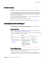
Contacting Brocade Technical Support
As a Brocade customer, you can contact Brocade Technical Support 24x7 online, by telephone, or by email. Brocade OEM customers contact their OEM/Solutions provider.
Brocade customers
For product support information and the latest information on contacting the Technical Assistance
Center, go to http://www.brocade.com/services-support/index.html.
If you have purchased Brocade product support directly from Brocade, use one of the following methods
to contact the Brocade Technical Assistance Center 24x7.
Online
Telephone
E-mail
Preferred method of contact for nonurgent issues:
Required for Sev 1-Critical and Sev
2-High issues:
[email protected]
• My Cases through MyBrocade
•
Continental US: 1-800-752-8061
• Software downloads and licensing •
tools
Europe, Middle East, Africa, and
Asia Pacific: +800-AT FIBREE
(+800 28 34 27 33)
• Knowledge Base
•
For areas unable to access toll
free number: +1-408-333-6061
•
Toll-free numbers are available in
many countries.
Please include:
•
Problem summary
•
Serial number
•
Installation details
•
Environment description
Brocade OEM customers
If you have purchased Brocade product support from a Brocade OEM/Solution Provider, contact your
OEM/Solution Provider for all of your product support needs.
• OEM/Solution Providers are trained and certified by Brocade to support Brocade® products.
• Brocade provides backline support for issues that cannot be resolved by the OEM/Solution Provider.
Brocade DCX 8510-8 Backbone Hardware Installation Guide
53-1002180-10
9
Document feedback
• Brocade Supplemental Support augments your existing OEM support contract, providing direct
access to Brocade expertise. For more information, contact Brocade or your OEM.
• For questions regarding service levels and response times, contact your OEM/Solution Provider.
Document feedback
To send feedback and report errors in the documentation you can use the feedback form posted with
the document or you can e-mail the documentation team.
Quality is our first concern at Brocade and we have made every effort to ensure the accuracy and
completeness of this document. However, if you find an error or an omission, or you think that a topic
needs further development, we want to hear from you. You can provide feedback in two ways:
• Through the online feedback form in the HTML documents posted on www.brocade.com.
• By sending your feedback to [email protected].
Provide the publication title, part number, and as much detail as possible, including the topic heading
and page number if applicable, as well as your suggestions for improvement.
10
Brocade DCX 8510-8 Backbone Hardware Installation Guide
53-1002180-10
About This Document
● Supported hardware and software.................................................................................. 11
● What’s new in this document.......................................................................................... 11
Supported hardware and software
This document includes information specific to the Brocade DCX 8510-8 running Brocade Fabric OS
version 7.0.0 and later.
What’s new in this document
The following changes have been made:
• Revised "WWN card removal and replacement" procedures due to new wwnrecover command.
• Revised "Verifying operation of the new CP blade" to add option of using the firmwaresync
command on the active CP blade to synchronize the firmware level on the replacement CP blade.
• Created "Installing inter-chassis links (ICL)" section, which includes considerations and
recommendations for using Brocade quad small form-factor pluggable QSFP transceivers and cables
for ICL connections.
• Added procedures for removing and replacing the Brocade 4x16 GFC 2 km QSFP transceiver to the
"Transceiver and cable removal and replacement" section.
• Revised the Technical Specifications section.
Brocade DCX 8510-8 Backbone Hardware Installation Guide
53-1002180-10
11
What’s new in this document
12
Brocade DCX 8510-8 Backbone Hardware Installation Guide
53-1002180-10
Product Overview
● Product features..............................................................................................................13
● Hardware components.................................................................................................... 14
● Supported blades............................................................................................................ 17
● Chassis slots numbering................................................................................................. 18
● Port numbering................................................................................................................18
● High availability............................................................................................................... 20
● Reliability.........................................................................................................................20
● Serviceability................................................................................................................... 21
● Software features............................................................................................................ 21
● Security........................................................................................................................... 22
● Network manageability....................................................................................................22
Product features
Key product features include the following:
• Up to 512 16-Gbps external ports in a single chassis , enabling high density SAN configurations with
reduced footprint.
• Support for 2, 4, 8, and 16-Gbps autosensing Fibre Channel ports. Trunking technology groups up to
eight ports to create high performance 128-Gbps ISL trunks between switches.
• 10-Gbps FC-type SFPs in 32/48-port 16-Gbps port blades, and 10-GbE SFPs in the FX8-24 and
FCOE10-24 application blades . The two types of SFPs are not interchangeable.
• The 10-Gbps ports can be manually configured on any port of the 32- and 48-port 16-Gbps port
blades.
• Support for many of the application, port blade, and control processor (CP) blades supported in the
Brocade DCX family of backbones (with the exception of the Core Switch Blade), thereby providing
flexible system configurations and fewer types of new blades.
• Beginning with Fabric OS v7.0.1, up to nine chassis can be connected with the use of 4x16-Gbps
quad SFP (QSFP) inter-chassis links (ICLs). Fabric OS v7.0.0 permits up to six chassis to be linked.
• Support for high-performance port blades running at 2, 4, 8, 10, or 16-Gbps, enabling flexible system
configuration.
• Redundant and hot-swappable control processor and core switch blades, power supplies, blower
assemblies, and WWN cards that enable a high availability platform and enable nondisruptive
software upgrades for mission-critical SAN applications.
• Universal ports that self-configure as E_Ports, F_Ports, EX_Ports and M_Ports (mirror ports). 10Gbps ports are E_Ports only.
• Diagnostic port (D_Port) functionality.
• In-flight data cryptographic (encryption/decryption) and data compression capabilities through the 16Gbps port blades when configured as ISLs.
• Fibre Channel over IP (FCIP) functionality through the FX8-24 blade.
• Fibre Channel over Ethernet (FCoE) capability through the FCOE10-24 blade.
Brocade DCX 8510-8 Backbone Hardware Installation Guide
53-1002180-10
13
Hardware components
Hardware components
The device has a modular and scalable mechanical construction that allows a wide range of flexibility
in installation, fabric design, and maintenance. The chassis can be mounted with the cables facing the
front of the equipment rack or to the rear, and consists of the following:
• Up to eight hot-swappable port blade assemblies that can be configured in a single chassis,
delivering up to 512 16-Gbps Fibre Channel ports .
• Two slots for control processor blades (CP8):
‐
A single active CP8 blade can control all the ports in the chassis.
‐
The standby CP8 blade assumes control of the chassis if the active CP fails.
• Two slots for core switch blades (CR16-8):
‐
‐
CR16-8 blade interconnects all port blades.
Inter-chassis link (ICL) connectors to connect to as many as nine neighboring chassis
using Fabric OS v7.0.1 or later. Only six chassis can be connected using Fabric OS v7.0.0.
‐
Both CR16-8 blades are active.
• Modular, hot-swappable port blades:
‐
32-port, 8-Gbps blades (FC8-32E)
‐
48-port, 8-Gbps blades (FC8-48E)
‐
64-port, 8-Gbps blades (FC8-64)
‐
32-port, 16-Gbps blades (FC16-32)
‐
48-port, 16-Gbps blades (FC16-48)
‐
64-port, 16-Gbps blades (FC16-64)
• Modular, hot-swappable application blades:
‐
FX8-24: 24-port (12 FC, 10 1-GbE, and 2 10-GbE) FCIP extension blade enabling long
distance communication over existing IP infrastructure.
‐
FCOE10-24: 24-port (24 10-GbE) CEE-based FCoE blade enabling enhanced connectivity
using existing Ethernet infrastructure. The FCoE blade can be used in the same chassis
with only the FC8-32E and FC16-32 port blade. The FCoE blade cannot be used with any
other FC port or application blades in the same chassis.
• Modular, hot-swappable encryption blades:
‐
FS8-18: 16-port, up to 4 blades per chassis, supporting in-flight data cryptographic
(encryption/decryption) and data-compression capabilities.
• Modular, hot-swappable field-replaceable units (FRUs):
‐
‐
Three blower assemblies.
Up to four power supplies (100-240 VAC autosensing).
‐
‐
‐
‐
At 110 VAC (nominal): Four power supplies are required for high availability.
220 VAC (nominal) is recommended for efficiency. Two or four power supplies
are provided depending on the quantity ordered. Refer to the power specifications
section in the Brocade DCX 8510 Technical Specifications on page 163 for
specific requirements for high availability.
‐
Redundant AC primary power connections ensure high availability. Each power
supply has its own connector, so the number of primary power connections is four
for optimum efficiency and redundancy.
Two WWN cards.
Blades use small form-factor pluggable (SFP+, mSFP, and QSFP) optical transceivers.
‐
‐
14
The 8-Gbps SFP+s and mSFPs auto-negotiate at 2, 4, and 8 Gbps.
The 10-Gbps speed must be manually set and requires special 10-Gbps FC SFP
+ transceivers.
Brocade DCX 8510-8 Backbone Hardware Installation Guide
53-1002180-10
Port side view of the device
‐
‐
The 16-Gbps SFP+ transceivers support speeds of 2, 4, 8, 10, and 16 Gbps.
The 16-Gbps QSFPs supported on FC16-64 port blade auto-negotiate at 4, 8, and
16 Gbps.
‐
The 16-Gbps QSFPs based inter-chassis link (ICL) on the core blades run at 64Gbps (four fixed 16-Gbps clustered in a single quad connector and cable).
• Blades are serviced from the port side of the chassis. Blowers, power supplies, and power cables are
serviced from the nonport side.
• World Wide Name (WWN) cards with status LEDs on the nonport side.
• Redesigned cable management comb and chassis door.
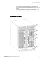
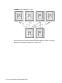
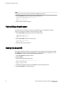
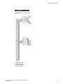
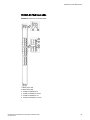
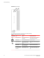
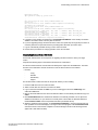
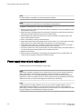
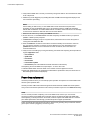
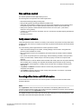
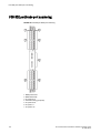
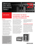
Port side view of the device
FIGURE 1 Port side of the Brocade DCX 8510-8 (sample configuration)
Brocade DCX 8510-8 Backbone Hardware Installation Guide
53-1002180-10
15
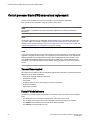
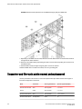
Nonport side view of the device
NOTE
Airflow is from the nonport side to the port side and out the exhaust vent.
1.
2.
3.
4.
5.
Exhaust vent
Core switch blade (CR16-8)
Control processor blade (CP8)
FC16-32 port blade
Cable management comb
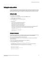
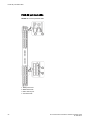
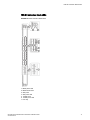
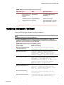
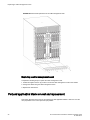
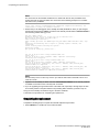
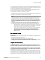
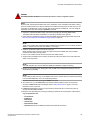
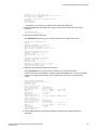
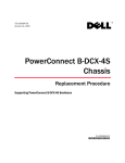
Nonport side view of the device
The following figure shows a sample configuration of the nonport side view of the Brocade DCX
8510-8.
FIGURE 2 Nonport side of the Brocade DCX 8510-8 (sample configuration)
1. WWN bezel (logo plate - WWN card behind)
2. Power supply
3. Blower assembly
16
Brocade DCX 8510-8 Backbone Hardware Installation Guide
53-1002180-10
Supported blades
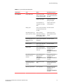
Supported blades
The following table summarizes the port, application, control processor, and core switch blades that are
supported in the device.
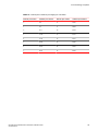
TABLE 1 Blades available for the device
Description
Name
Function
Control processor
blade
CP8
The CP8 blade contains the control plane for the chassis. There are
two CP8 blades for redundancy. This control processor blade is
compatible with the Brocade DCX 8510-8, Brocade DCX 8510-4,
Brocade DCX-4S, and Brocade DCX platforms.
Core switch blade
CR16-8
The CR16-8 blade contains the ASICs for switching between port
blades. Every port blade connects to each core switch blade. There
can be up to 512 16-Gbps or 8-Gbps total ports for port blades.
Each core switch blade connects to 128 backplane ports. Core
switch blades have additional front port connectivity to connect
multiple chassis and backplane connections for the storage server
blade. This core switch blade is compatible only with the Brocade
DCX 8510-8. Requires specific type of QSFP transceivers.
32-port 8-Gbps port
blade
FC8-32E
A 32-port Brocade port blade supporting 2, 4, and 8 Gbps Fibre
Channel port speeds. This port blade is compatible with the Brocade
Brocade DCX 8510-8 and Brocade DCX 8510-4 This blade requires
Fabric OS v7.0.1 or later to run in this chassis.
48-port 8-Gbps port
blade
FC8-48E
A 48-port Brocade port blade supporting 2, 4, and 8 Gbps Fibre
Channel port speeds. This port blade is compatible with the Brocade
DCX 8510-8 and Brocade DCX 8510-4. This blade requires Fabric
OS v7.0.1 or later to run in this chassis.
64-port 8-Gbps port
blade
FC8-64
A 64-port Brocade port blade supporting 2, 4, and 8 Gbps port
speeds with mSFPs. This port blade is compatible with the Brocade
DCX 8510-8, Brocade DCX 8510-4, Brocade DCX-4S, and Brocade
DCX platforms.
32-port 16-Gbps port
blade
FC16-32
A 32-port Brocade port blade supporting 2, 4, 8, 10, and 16 Gbps
Fibre Channel port speeds. The blade also supports port-based inflight encryption/decryption and compression/decompression. This
port blade is compatible with the Brocade DCX 8510-8 and Brocade
DCX 8510-4 and requires Fabric OS v7.0.0 or later to run in this
chassis.
48-port 16-Gbps port
blade
FC16-48
A 48-port Brocade port blade supporting 2, 4, 8, 10, and 16 Gbps
Fibre Channel port speeds. The blade also supports port-based inflight encryption/decryption and compression/decompression. This
port blade is compatible with the Brocade DCX 8510-8 and Brocade
DCX 8510-4 and requires Fabric OS v7.0.0 or later to run in this
chassis.
Brocade DCX 8510-8 Backbone Hardware Installation Guide
53-1002180-10
17
Chassis slots numbering
TABLE 1 Blades available for the device (Continued)
Description
Name
Function
64-port 16-Gbps port
blade
FC16-64
A 64-port Brocade port blade supporting 4, 8, and 16-Gbps Fibre
Channel port speeds. The blade also supports port-based in-flight
encryption/decryption and compression/decompression. This port
blade is compatible with the Brocade DCX 8510-8 and Brocade
DCX 8510-4 and requires Fabric OS v7.3.0 or later to run in this
chassis. Requires specific type of QSFP transceivers and those are
not the same as used in the core blades.
Fibre Channel over
Ethernet blade
FCOE10-24
The FCOE10-24 blade enables FCoE functionality over existing
Ethernet infrastructure utilizing CEE protocols. It has 24 10-GbE
ports available. This FCoE application blade is compatible with the
Brocade DCX 8510-8, Brocade DCX-4S, and Brocade DCX
platforms. This FCoE blade can be used in the same chassis with
only the FC8-32E and FC16-32 port blades. This FCoE blade
cannot be used with any other FC port blades or application blades
in the same chassis. Refer to the Fabric OS Release Notes for
limitations in using this blade.
Storage encryption
blade
FS8-18
The FS8-18 blade enables data cryptographic (encryption/
decryption) and data-compression capabilities for data-at-rest. It has
16 Fibre Channel optical SFP ports. This application blade is
compatible with the Brocade DCX 8510-8, Brocade DCX 8510-4,
Brocade DCX-4S, and Brocade DCX platforms and requires Fabric
OS v7.0.0 or later to run in the 8510-4 and 8510-8 chassis.
FCIP extension blade FX8-24
The FX8-24 blade enables FCIP functionality over existing IP
infrastructure. It has 12 FC ports, 10 1-GbE ports, and two 10-GbE
ports available. This application blade is compatible with the
Brocade DCX 8510-8, Brocade DCX 8510-4, Brocade DCX-4S, and
Brocade DCX platforms and requires Fabric OS v7.0.0 or later to
run in the DCX 8510-4 and DCX 8510-8 chassis.
Chassis slots numbering
The chassis slots are numbered and used for the following purpose.
•
•
•
•
•
Numbered 1 through 12, from left to right when facing the port side of the Brocade DCX 8510-8.
Slots 6 and 7 can be used only to install the control processor blades (CP8).
Slots 5 and 8 can be used only to install the core switch blades (CR16-8).
Slots 1-4 and 9-12 can be filled with port, application, or encryption blades.
Unused slots must be filled with blade filler panels to maintain adequate cooling.
Port numbering
The device uses the following port numbering method.
18
Brocade DCX 8510-8 Backbone Hardware Installation Guide
53-1002180-10
Product Overview
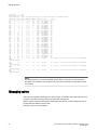
TABLE 2 Port numbering and trunking port groups
Blade
Port numbering
Trunking port groups
CR16-8 core
blade
• 0 through 7 from bottom to top on the left set
of ports.
• 8 through 15 from bottom to top on the right
set of ports.
• Trunk group 0: QSFP ports 0-3 and 8-11.
• Trunk group 1: QSFP ports 4-7 and
12-15.
Each connector is a group of four 16Gbps ports. For supported QSFPs, refer
to Qualified transceivers for the FC16-64
and CR16-x blades on page 52
NOTE
CR16-8 core blade
Individual FC ports within the same QSFP
port cannot form a trunk. A trunk has to
comprise of individual FC ports from
different QSFP ports.
FC8-32E port
blade
• 0 through 15 from bottom to top on the left set Trunk groups: 0-7, 8-15, 16-23, and 24-31.
of ports.
• 16 through 31 from bottom to top on the right
set of ports.
FC8-48E port
blade
• 0 through 23 from bottom to top on the left set
Trunk groups: 0-7, 8-15, 16-23, 24-31,
of ports
32-39, and 40-47.
• 24 through 47 from bottom to top on the right
set of ports.
FC8-64 port
blade
• 0 through 31 from bottom to top on the left set • Trunk groups: 0-7, 8-15, 16-23, 24-31,
of ports.
32-39, 40-47, 48-55, and 56-63.
• 32 through 63 from bottom to top on the right
(* - Octet 56-63 E_Port trunks are
set of ports.
permitted on the logical or base switch
only.)
FC16-32 port
blade
•
FC16-48 port
blade
•
FC16-64 port
blade
•
0 through 15 from bottom to top on the left set • Trunk groups: 0-7, 8-15, 16-23, and
of ports.
24-31.
• 16 through 31 from bottom to top on the right
set of ports.
0 through 23 from bottom to top on the left set • Trunk groups: 0-7, 8-15, 16-23, 24-31,
of ports.
32-39, and 40-47.
• 24 through 47 from bottom to top on the right
set of ports.
0 through 63 from bottom to top.
Trunk groups: 0-7, 8-15, 16-23, 24-31,
32-39, 40-47, 48-55, and 56-63.
These are QSFP ports 0-15. For supported
QSFPs, refer to Qualified transceivers for
the FC16-64 and CR16-x blades on page
52.
FCOE10-24
blade
•
0 through 23 in two vertical rows from bottom
left to top right.
Brocade DCX 8510-8 Backbone Hardware Installation Guide
53-1002180-10
N/A
19
High availability
TABLE 2 Port numbering and trunking port groups (Continued)
Blade
Port numbering
Trunking port groups
FS8-18 blade
• 16 FC ports: 0 through 15 from bottom to top.
• Two 10/100/1000 BaseT ports: GE0 and GE1
from the bottom.
•
•
FX8-24 blade
• FC ports labeled FC on the front panel: 0
• Trunk group 0: FC ports 0-1
through 11 in two vertical columns of six ports • Trunk group 1: FC ports 6-7
starting from the bottom left and bottom right
• Trunk group 2: FC ports 2-5 and 8-11
in the lower group of 12 ports.
• Two 10-GbE ports labeled 10GE on the front
panel: 0 and 1 in the left column just above
the FC ports.
• 1-GbE ports labeled GE on the front panel: 0
through 9 in both columns above the FC and
10GE ports.
Trunk group 0: FC ports 0-7
Trunk group 1: FC ports 8-15
High availability
The following features contribute to the high availability the device:
•
•
•
•
•
•
•
Redundant, hot-swappable FRUs, including blades, power supplies, blowers, and WWN cards
Enhanced data integrity on all data paths
Fabric Shortest Path First (FSPF) rerouting around failed links
Integration with Simple Network Management Protocol (SNMP) managers
Automatic control processor failover
Nondisruptive "hot" software code loads and activation
Easy configuration, save, and restore
The high availability software architecture provides a common framework for all applications that
reside on the system, allowing global and local states to be maintained through any component failure.
High availability elements consist of the High Availability Manager, the heartbeat, the fault/health
framework, the replicated database, initialization, and software upgrade.
The High Availability Manager controls access to the standby control processor, facilitates software
upgrades, prevents extraneous CP failover activity, closes and flushes streams, provides flow control
and message buffering, and supports a centralized active and standby state.
Reliability
The device uses the following error detection and correction mechanisms to ensure reliability of data:
• Error Detection and Correction over main control processor memory.
• Error Detection and Correction mechanism, which checks for encoder errors and fault isolation
(EDFI), such as cyclic redundancy checking (CRC), parity checking, checksum, and illegal address
checking.
• Power-on self-test (POST).
• Dual control processors that enable hot, nondisruptive fast firmware upgrades.
• One serial port and two Ethernet ports (on each control processor) for management and for service.
Offline control processor diagnostics and remote diagnostics simplify troubleshooting. The standby
20
Brocade DCX 8510-8 Backbone Hardware Installation Guide
53-1002180-10
Serviceability
control processor monitors diagnostics to ensure the system is operational should a failover be
necessary.
• Bus monitoring and control of blades and other field-replaceable units (FRUs).
Serviceability
The device provides the following features to enhance and ensure serviceability:
• Modular design with hot-swappable components.
• Flash memory that stores two firmware images per control processor.
• USB port on control processor blades for most tasks that formerly required an FTP/SCP server,
including software and firmware upgrades.
• Nonvolatile random-access memory (NVRAM), containing the OEM serial number, Brocade serial
number, revision information, and part number information.
• Background health-check daemon.
• Memory scrubber, self test, and bus ping to determine if a bus is not functioning.
• RASlog messages.
• SMI-S compliant.
• Hardware and software watchdog timers.
• Status LEDs.
• Predictive diagnostics analysis through Fabric Watch.
• SNMP (including version 3) integration with higher-layer managers.
Software features
The Fabric OS allows any Fibre Channel-compliant device to attach to the switches as long as it
conforms to the device login, name service, and related Fibre Channel standards. Each operating
environment requires that a Fibre Channel host bus adapter (HBA) be available with a standardscompliant driver for correct interface to the fabric.
Fabric OS consists of a set of embedded applications running on top of an embedded Linux operating
system kernel. Some of these applications include:
•
•
•
•
•
•
•
•
•
Name server
Alias server
Zone server
Simple Network Management Protocol (SNMP) agent
SMI-S compliant API
Syslog auditing
Reliable Commit Service (RCS)
NTP
Tasks to manage address assignment, routing, link initialization, fabric initialization, link shutdown,
the device shutdown, and the user interface
Brocade DCX 8510-8 Backbone Hardware Installation Guide
53-1002180-10
21
Security
Security
The following list highlights some of the key security features available in the device and in other
Brocade enterprise-class products running Fabric OS 7.0.1 or later. For details, contact your device
supplier and refer to the Brocade White Paper, "The Growing Need for Security in Storage Area
Networks."
•
•
•
•
•
•
•
•
•
•
•
•
•
•
•
•
•
•
•
•
•
•
•
•
•
•
•
•
•
•
•
•
•
•
DH-CHAP
SSHv2 (using AES, 3DES, RSA)
HTTPS (using AES)
SNMPv3
FC-SP
Secure RPC
Secure file copy (SCP)
Telnet disable
Telnet timeout
IP filters (block listeners)
Secure passwords (centralized control through RADIUS/CHAP)
Multiple user accounts (MUAs) (Up to 255)
Role-based access controls (RBACs)
Administrative domains/Virtual fabrics
Boot PROM password reset
Password hardening policies
Up front login in Web Tools
Login banner
Monitoring of attempted security breaches (through audit logging)
Monitoring of attempted security breaches (through Fabric Watch Security Class)
Fibre Channel security policies: DCC and SCC
Trusted Switch (FCS) for central security management
Management access controls (SNMPv3, Telnet, FTP, serial port, front panel)
Hardware-enforced zoning by WWN, domain/port ID, or both
Default zoning
RSCN suppression and aggregation
Configurable RSCN suppression by port
NTPv3 (to synchronize timestamps)
Event auditing
Change tracking
Firmware change alerts in Fabric Manager
Persistent port disable
Persistent domain ID
E_Port disable
Network manageability
The device has a single domain and is managed as a single element with Brocade Network Advisor.
The device responds to its own IP address and appears as a separate entity to the Telnet protocol and
SNMP.
22
Brocade DCX 8510-8 Backbone Hardware Installation Guide
53-1002180-10
Product Overview
All management interfaces, such as Telnet, Web Tools, standards-compliant SMI-S, and Management
Server, support a "port N within blade M" naming scheme.
The device supports SNMPv1 and SNMPv3. When SNMP devices send SNMP messages to a
management console running SAN management software, the information is stored in a management
information base (MIB). Fabric OS v7.0.0 and later supports the latest Fibre Alliance Fibre Channel
Management (FCMGMT) and Storage Management Initiative (SMI) MIBs, which allow common
information necessary for management software to provide information to a SAN administrator. Refer to
the Fabric OS MIB Reference for additional MIB information.
Brocade DCX 8510-8 Backbone Hardware Installation Guide
53-1002180-10
23
Network manageability
24
Brocade DCX 8510-8 Backbone Hardware Installation Guide
53-1002180-10
Device Installation
● Time and items required................................................................................................. 25
● Preparing for the installation........................................................................................... 26
● Unpacking and installing the device................................................................................27
● Items included with the device........................................................................................ 28
● Providing power to the device......................................................................................... 29
● Cable management.........................................................................................................29
Time and items required
You can set up and install the device in the following ways:
• As a standalone unit on a flat surface.
• In a 19-inch Electronic Industries Association (EIA) cabinet, using the 14U Rack Mount Kit that is
provided with the device.
• In a mid-mount telecommunications (Telco) rack, using the Mid-Mount Rack Kit available from your
device supplier.
This chapter describes how to set up the device as a standalone unit. For rack-mount installation
instructions, refer to the appropriate manual as described in the following table.
The following table describes the main installation and setup tasks, the estimated time required for
each, and the items required to complete the task for a device that is fully populated with FC16-64 port
blades. Configurations with fewer blades or ports require less time. These time estimates assume a
prepared installation site and appropriate power and network connectivity.
TABLE 3 Installation tasks, time, and items required
Installation task
Time estimate
Items required
Site preparation and unpacking
the device
30 minutes
1/2-in. socket wrench (to remove pallet bolts).
#2 Phillips screwdriver(for cable management comb).
Pallet jack.
Hydraulic lift or assisted lift, able to raise to a minimum of
140 cm (55 in.), with a minimum capacity of 115 kg (254
lb).
To know the weight of your device fully populated with the
required port blades, refer to the Brocade DCX 8510
Technical Specifications on page 163.
Installing rack mount kit or Port
Side Exhaust Kit
30 minutes
Mounting and securing the device 30 minutes
in rack
Brocade DCX 8510-8 Backbone Hardware Installation Guide
53-1002180-10
Refer to the one or more of the following documents:
•
•
14U Rack Mount Kit Installation Procedure
Mid-Mount Rack Kit (Backbone) Installation Procedure
25
Preparing for the installation
TABLE 3 Installation tasks, time, and items required (Continued)
Installation task
Time estimate
Items required
Installing power cables and
powering on the device
20 minutes
Power cables (provided in the device accessories kit).
Establishing serial connection,
logging in to the device, and
configuring IP addresses
20 minutes
Serial cable (provided in the accessory kit).
Workstation computer with a serial port or terminal server
port and a terminal emulator application (such as
HyperTerminal).
Ethernet IP addresses for the device and for both control
processor blades: total three addresses.
Installing an Ethernet cable,
20 minutes
opening a Telnet session, and
configuring the device domain ID,
date and time, and additional
system parameters. Verify and
back up configuration.
Installing transceivers as needed
Ethernet cabling (optional) for Telnet access.
Refer to the Fabric OS Administrator's Guide.
20-30 minutes or SFP+, mSFP, and QSFP optical transceivers as needed.
longer if you are
using high-density
port blades.
Attaching fiber-optic cables, cable 2-3 hours
ties, and cable guides
Fiber-optic cables, cable ties, and cable management
comb.
Preparing for the installation
Read the following sections before preparing to install the device.
• Caution and Danger Notices on page 177.
• Brocade DCX 8510 Technical Specifications on page 163; power supply specifications section and
plan for meeting the power supply standards based on your device configuration.
• Managing cables on page 54 and plan for cable management.
The following steps are required to ensure correct installation and operation.
1. Ensure that the following amount of space is available in the rack.
• 14 rack units (14U) high.
• 61.29 cm (24.09 inch) deep.
• 43.74 cm (17.22 inch) wide.
1U is equal to 4.45 cm (1.75 inches).
Plan to install the device with the nonport side facing the air-intake aisle. The device can be
installed facing either direction, if serviceability and cooling requirements are met.
2. Ensure that dedicated electrical branch circuits with the following characteristics are available:
• 200 - 240 VAC, 50-60 Hz, two branch circuits are recommended for high availability and
maximum blade usage when configured with 192 or more 16-Gbps ports.
• 200 - 240 VAC, 50-60 Hz, four branch circuits are recommended for high availability and
maximum blade usage when configured with 384 or more 16-Gbps ports.
26
Brocade DCX 8510-8 Backbone Hardware Installation Guide
53-1002180-10
Unpacking and installing the device
•
•
•
•
•
•
110 - 120 VAC, 50-60 Hz, four branch circuits are highly recommended.
Two or four cables for 200 - 240 VAC service; up to four cables for 110 - 120 VAC service
Protected by a circuit breaker in accordance with local electrical codes
Supply circuit, line fusing, and wire size adequate to the electrical rating on the chassis nameplate
Location close to the chassis and easily accessible
Grounded outlets installed by a licensed electrician and compatible with the power cords
CAUTION
Use a separate branch circuit for each power cord, which provides redundancy in case one of
the circuits fails.
3. Plan for cable management before installing the chassis.
Cables can be managed in a variety of ways, such as by routing cables below the chassis, to either
side of the chassis, through cable channels on the sides of the cabinet, or by using patch panels.
4. Ensure that the following is available for configuration of the device:
•
•
•
•
Workstation with an installed terminal emulator, such as HyperTerminal
Serial cable (provided)
Three Ethernet cables (including one spare)
Access to an FTP server for backing up the switch configuration or collecting supportsave output
data (optional)
• A Brocade USB stick for collecting supportsave output data (optional)
• Transceivers (copper and optical) and compatible cables
5. Ensure that the air intake and exhaust vents have a minimum of 5.1 cm (2 in.) of airspace.
6. Ensure that the air temperature on the air intake side is less than 40°C (104°F) during operation.
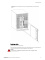
Unpacking and installing the device
Use the following procedure to unpack and install your device.
DANGER
A fully populated Brocade DCX 8510-8 (eight FC16-64 port cards, 512 ports) weighs
approximately 161.2 kg (355 lbs) and requires a hydraulic or assisted lift to install it.
1. Unpack the device.
a)
b)
c)
d)
Cut the bands that encircle the packaging.
Remove the lid and the kits and foam from the top of the chassis.
Lift the cardboard box off the chassis and remove the plastic bag from around the
chassis.Save the packing materials for use when returning the old chassis.
Leave the chassis on top of the plastic shipping tray if the chassis must be transported to
the installation location.
NOTE
The device packaging does not incorporate a wood pallet and pallet brackets. The chassis
sits on top of a plastic shipping tray.
2. Use a pallet jack or other assisted lift to transport the new chassis to the installation area. Doorways
must be wider than 36 in. (91 cm) to accommodate the chassis.
3. Remove the following items from the chassis and set aside.
Brocade DCX 8510-8 Backbone Hardware Installation Guide
53-1002180-10
27
Items included with the device
•
•
•
•
14U Rack Mount Kit
Accessory kit
Packing foam
Antistatic plastic
4. Remove the chassis door from the device.
5. Remove the cable management comb.
6. Use a lift to raise the chassis to the correct level. If installing the chassis in a cabinet, follow the
instructions provided by the rack kit manufacturer.
7. If applicable, lock the wheels of the lift.
8. Gently slide the chassis onto the final installation surface, ensuring that it remains supported during
the transfer.
9. Ensure that the chassis is oriented so that the nonport side has access to intake air (cool).
10.Reinstall the cable management comb.
11.Reinstall the door. The door must be installed to meet EMI compliance.
Items included with the device
The device ships with the following:
• The chassis, populated with:
‐
‐
‐
Control processor blades (CP8)
Core switch blades (CR16-8)
Port blades, application blades, and encryption blades (included based on customer
specification)
‐
Blade slot filler panels (for slots not filled by blades)
‐
WWN cards
‐
WWN bezel (logo plate)
‐
Power supplies
‐
Power supply filler panel (included if there are fewer than four power supplies)
‐
Blower assemblies
‐
Cable management comb
‐
Chassis door
• Accessory kit containing the following items:
‐
‐
‐
‐
A QuickStart Guide
ESD grounding strap
USB device
RS-232 serial cable. The RS-232 cable has an adapter at one end that can be removed to
provide an RJ-45 style connector.
• 14U Rack Mount Kit with instructions (includes rear brackets and bottom support rails)
Order the Brocade-branded optical transceivers (SFP+, mSFP, and QSFP). The device supports SWL,
LWL, and ELWL transceivers. The mSFPs and QSFPs are SWL transceivers only.
NOTE
For information about the SFP+, mSFP, and QSFP transceivers that are qualified for the device, refer
to Transceiver and fiber optic cable removal and replacement on page 118.
28
Brocade DCX 8510-8 Backbone Hardware Installation Guide
53-1002180-10
Providing power to the device
Providing power to the device
For this procedure, refer to the power supply specifications section in the Brocade DCX 8510 Technical
Specifications on page 163 for power supply requirements of your chassis.
Complete the following steps to provide power to the chassis.
DANGER
Make sure that the power source circuits are properly grounded, then use the power cord
supplied with the device to connect it to the power source.
1. Connect the AC power cords to the power supply assemblies. Two or four power cords are required
depending on electrical service and if the high availability option is selected.
2. Connect the power cords to a power source with voltage of 200 to 240 VAC, 47 to 63 Hz (normally
two power cords or as many as four) or optionally to a power source with voltage of 110 to 120 VAC,
47 to 63 Hz (up to four power cords).
NOTE
Use of the high-voltage line (200 to 240 VAC) is highly recommended because of better powerconversion efficiency. A Brocade DCX 8510-8 chassis fully loaded with 16 Gbps port blades (512
ports total) should be supplied with four power supplies connected to 200-240 VAC lines.
3. Switch the AC power switches on the power supplies to I. The AC power switches light green when
switched on and power is supplied.
The device performs a power-on self-test (POST) each time it is powered on. POST takes
approximately 10 minutes and is complete when the indicator light activity displays the operational
state. You can bypass POST by using the fastBoot command. You can also disable POST for
successive reboots on the device using the diagDisablePost command.
NOTE
Do not connect the switch to the network until the IP addresses are configured.
For information about LED patterns, refer to System Monitoring on page 57.
Cable management
The cable management comb (Port side view of the device on page 15) is attached to the chassis under
the chassis door and allows for simple cable management. The comb can be installed without service
disruption.
NOTE
The minimum radius to which a 50 micron cable can be bent under full tensile load is 5.1 cm (2 in.). For
a cable under no tensile load, that minimum is 3.0 cm (1.2 in.).
Brocade DCX 8510-8 Backbone Hardware Installation Guide
53-1002180-10
29
High-density cabling for the FC8-64 port blade
CAUTION
Before plugging a cable into to any port, be sure to discharge the voltage stored on the cable
by touching the electrical contacts to ground surface.
Cables can be organized and managed in a variety of ways, for example, using cable channels on the
sides of the cabinet or patch panels to minimize cable management. Following is a list of
recommendations:
NOTE
You should not use tie wraps with optical cables because they are easily overtightened and can
damage the optic fibers.
• Plan for rack space required for cable management before installing the switch.
• Leave at least 1 m (3.28 ft) of slack for each port cable. This provides room to remove and replace
the switch, allows for inadvertent movement of the rack, and helps prevent the cables from being
bent to less than the minimum bend radius.
• If you are using Brocade ISL Trunking, consider grouping cables by trunking groups. The cables
used in trunking groups must meet specific requirements, as described in the Fabric OS
Administrator’s Guide .
• For easier maintenance, label the fiber-optic cables and record the devices to which they are
connected.
• Keep LEDs visible by routing port cables and other cables away from the LEDs.
• Use Velcro ® type straps to secure and organize fiber-optic cables.
NOTE
Do not route the cables in front of the air exhaust vent, which is located at the top of the port side of
the chassis.
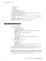
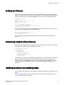
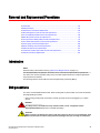
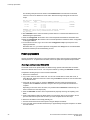
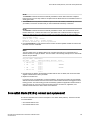
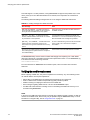
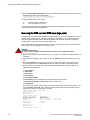
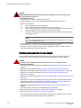
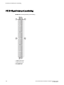
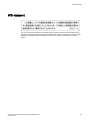
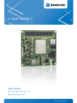
High-density cabling for the FC8-64 port blade
The FC8-64 high density port blade cannot use the standard LC cables because the pitch between
optics in the new mini-SFP (mSFP) transceiver is smaller than in standard SFPs. Patch cables and
panels can be used to attach standard size cabling to the blade if necessary. The following figure
illustrates the mSFP to SFP patch cable. Refer to "Best Practices Guide: High Density Cable
Management Solutions" (available at http://www.brocade.com ) for cable management guidelines for
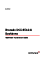
high-density port solutions, and cable and patch panel part numbers.
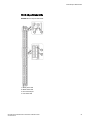
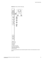
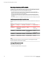
FIGURE 3 Cable design for the mSFP patch cables for the FC8-64 high density port blade
1. mSFP connector
2. Duplex clip (black)
30
Brocade DCX 8510-8 Backbone Hardware Installation Guide
53-1002180-10
Qualified cables for the FC8-64 port blade
3. 6 mm cable
4. SFP connector
Note that the duplex clip on the mSFP end of the cable is black for easier recognition. For a listing of the
qualified mSFP optical cables for the FC8-64 port blade, refer to Qualified cables for the FC8-64 port
blade on page 31.
If ISL Trunking is in use, group the cables by trunking group. The ports are color-coded to indicate
which ports can be used in the same ISL Trunking group: eight ports marked with solid black ovals
alternate with eight ports marked with oval outlines.
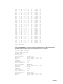
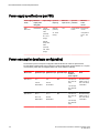
Qualified cables for the FC8-64 port blade
The following table lists the third-party cables that have been qualified for use with the mSFP
transceivers in the FC8-64 high density port blade.
TABLE 4 Qualified cables for mSFP connections for the FC8-64 high density port blade
Description
Length Corning part number
Patch cables - mSFP to LC
Molex part
number
S50502S5120XXXM (XXX
= length)
Amphenol part
number
943-99865-1XXXX
(XXXX = length)
mSFP LC - standard LC,
duplex, multi-mode, OM3,
50/125
1m
S50502S5120001M
106273-0525
943-99865-10001
mSFP LC - standard LC,
duplex, multi-mode, OM3,
50/125
2m
S50502S5120002M
106273-0526
943-99865-10002
mSFP LC - standard LC,
duplex, multi-mode, OM3,
50/125
3m
S50502S5120003M
106273-0527
943-99865-10003
mSFP LC - standard LC,
duplex, multi-mode, OM3,
50/125
5m
S50502S5120005M
106273-0528
943-99865-10005
mSFP LC - standard LC,
duplex, multi-mode, OM3,
50/125
10 m
S50502S5120010M
106273-0529
943-99865-10010
Patch cables - mSFP to mSFP
S5S502S5120XXXM (XXX
= length)
943-99866-1XXXX
(XXXX = length)
mSFP LC - mSFP LC, duplex,
multi-mode, OM3, 50/125
1m
S5S502S5120001M
106273-0560
943-99866-10001
mSFP LC - mSFP LC, duplex,
multi-mode, OM3, 50/125
2m
S5S502S5120002M
106273-0561
943-99866-10002
Brocade DCX 8510-8 Backbone Hardware Installation Guide
53-1002180-10
31
Cable types supported on the FC16-64 port blade
TABLE 4 Qualified cables for mSFP connections for the FC8-64 high density port blade (Continued)
Description
Length Corning part number
Molex part
number
Amphenol part
number
mSFP LC - mSFP LC, duplex,
multi-mode, OM3, 50/125
3m
S5S502S5120003M
106273-0562
943-99866-10003
mSFP LC - mSFP LC, duplex,
multi-mode, OM3, 50/125
5m
S5S502S5120005M
106273-0563
943-99866-10005
mSFP LC - mSFP LC, duplex,
multi-mode, OM3, 50/125
10 m
S5S502S5120010M
106273-0564
943-99866-10010
Trunk cables - mSFP to MTP
tbd
mSFP LC - MTP-female, 12
fiber, 12" breakout, OM3,
50/125
H93S5TE9-BMU-XXXM
(XXX = length)
943-99867-1XXXX
(XXXX = length)
mSFP LC - MTP-female, 12
fiber, 6" breakout, OM3,
50/125
2m
106272-0327
mSFP LC - MTP-female, 24
fiber, 12" breakout, OM3,
50/125
2m
106272-0328
Bag of clips (quantity 64)
TRIGGER-BP-NP
n/a
n/a
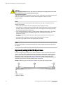
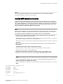
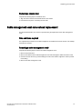
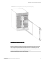
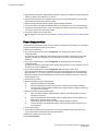
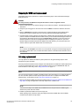
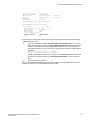
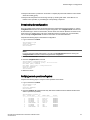
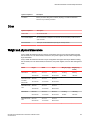
Cable types supported on the FC16-64 port blade
The FC16-64 port blade supports simplified cable management using QSFP cables. Each QSFP cable
has four links internally that run at 16-Gbps speed and the cables come in specific predetermined fixed
lengths.
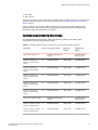
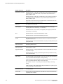
The FC16-64 port blade supports the following types of cables:
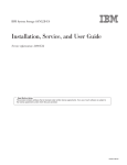
• QSFP to QSFP standard cables
• QSFP-SFP/LC Break-out/Split-out cables
32
Brocade DCX 8510-8 Backbone Hardware Installation Guide
53-1002180-10
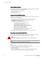
Installing inter-chassis links (ICLs)
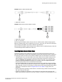
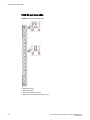
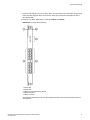
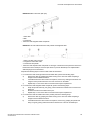
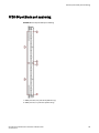
FIGURE 4 QSFP to QSFP standard cables
1. QSFP MTP connector
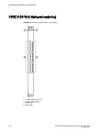
FIGURE 5 QSFP-SFP/LC Break-out/Split-out cables
1. QSFP MTP connector
2. SFP+ LC connectors
With the support for breakout cables, each port can be in a different mode. Inside the single physical
QSFP port, individual ports can be configured as an E_Port, F_Port or EX_Port. Also, each internal port
inside a single physical QSFP can be part of different Logical Switches.
With the support for breakout cables, trunking can be enabled on ports in a QSFP port group, with ports
connected through breakout cables at the other end.
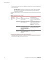
Installing inter-chassis links (ICLs)
Follow these guidelines when installing ICLs using fiber optic cables and transceivers. Refer to the
Fabric OS Administrator's Guide for the configuration procedure and requirements. Refer to "Removing
and replacing a QSFP and cable" in this hardware installation guide to install cables and transceivers.
• The QSFP ports on the core switch blades can be used only with an inter-chassis link (ICL) license.
After the addition or removal of a license, the license enforcement is performed on the ports only
when the portdisable and portenable commands are issued on the ports. An ICL license must be
installed on all Brocade Backbones forming the ICL connection. Up to nine neighboring Brocade
DCX 8510 series chassis can be connected with the MTP cables.
• An off-the-shelf MTP cable up to 100 meters can be used as an ICL cable when using the standard
SWL optics. The Brocade 2 km QSFP with LWL optics has an integrated 3 meter single-mode pigtail
with a male MTP connector for connectivity to a patch panel or female terminated MTP patch cable to
achieve up to 2 km distances. Refer to Using Brocade 2 km LWL QSFPs on page 38 for more
information.
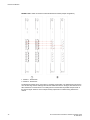
• Brocade supports fully populating a switch with ICL connections using a mixture of 50 and 100 meter
SWL optics and 2 km LWL optics.
• Following are examples of maximum ICL port connections in a DCX 8510 when using 2 km LWL
QSFPs. Note that limits are based on the number of buffers. If using ICLs for shorter distances, more
Brocade DCX 8510-8 Backbone Hardware Installation Guide
53-1002180-10
33
Device Installation
ICL ports can be connected. There are no limitations on number of ICL ports if all ICL distances are
a few hundred meters.
‐
‐
Up to 10 ICL ports can be used for 2 km distances when 16 buffer credits are configured
per virtual channel.
Up to 16 ICL ports can be used for 1,375 meter distances when 11 buffer credits are
configured per virtual channel.
The following table describes the connector port LED patterns and the recommended actions for those
patterns.
TABLE 5 ICL QSFP connector port LEDs
LED purpose
Color
Status
Recommended action
QSFP connector
status
No light (LED is No QSFP module, all four QSFP
off)
ports are disabled.
No action is required if QSFP not
present or verify that the QSFP is fully
inserted.
Steady amber
QSFP module is in, all four ports
have no signal/no sync.
No action required if QSFP only is
installed or ensure that the cable is
properly connected. If the LED
remains amber, consult the device
supplier.
Blinking amber
Port is disabled or faulted, FC link
activity, segmented, loopback
mode, also during transition
between MTP cable insertion and
confirmation.
Check for console messages or wait
for all four ports to come online.
Steady green
Both ends of MTP cable are in and
all ports are online. Full link is
established.
No action required.
The following figures illustrate types of MTP cables and transceivers:
• Separate MTP cable and transceiver. The transceiver is inserted into the blade port connector and
the cable plugs into a QSFP on the other end of the ICL.
34
Brocade DCX 8510-8 Backbone Hardware Installation Guide
53-1002180-10
Possible ICL configurations
1
2
MTP cable
Transceiver
FIGURE 6 MTP cable and transceiver
NOTE
If the fiber optic cables are not connected to transceivers, make sure the rubber gaskets are plugged
into the transceivers.
• Brocade 2 km LWL QSFP transceiver with integrated MTP cable. The transceiver is inserted into the
blade port connector and integrated cable plugs into a QSFP on the other end of the ICL, a patch
panel, or a patch cable.
1
2
3
MTP 1x12 fiber male connector
Integrated 3 meter MTP cable
Transceiver with pull-tab
FIGURE 7 2 km QSFP with integrated cable
• A third type of transceiver has a pull-tab to aid in removing the transceiver from the port connector
(like shown in previous illustration), but has a separate MTP cable that plugs into the transceiver.
The QSFP connectors on the core blades are labeled by trunk group (trunking is optional) for ease of
installation.
Possible ICL configurations
The following figures show acceptable cabling configurations for the ICL feature. The recommended
topology is the parallel type where there are four QSFP cables connected between any pair of Brocade
DCX 8510 series chassis. The full-mesh configuration is also supported. Each of two cores in one
chassis should be interconnected with each of two cores in the second chassis. This provides for interchassis link (ICL) trunking between chassis, ensuring redundancy. Parallel connections between core
blades are recommended.
Brocade DCX 8510-8 Backbone Hardware Installation Guide
53-1002180-10
35
Device Installation
FIGURE 8 QSFP cable connections for Brocade DCX 8510 chassis (sample configuration)
1. Chassis 1 - DCX 8510-8
2. Chassis 2 - DCX 8510-4
The DCX 8510 chassis can be connected in a core/edge configuration. The following figure shows two
core and four edge chassis. Although DCX 8510-8 chassis are shown in the figure, the chassis can be
either DCX 8510-4 or DCX 8510-8. The cabling scheme should follow the parallel example shown in
the previous figure. Each line in the example actually represents four cables running between the
chassis.
36
Brocade DCX 8510-8 Backbone Hardware Installation Guide
53-1002180-10
Device Installation
FIGURE 9 DCX 8510 core/edge ICL topology
The DCX 8510 chassis can also be connected in a full mesh configuration as shown in the following
figure. Although DCX 8510-8 chassis are shown in the figure, the chassis can be either DCX 8510-4 or
DCX 8510-8. In this example, the trunk groups are shown in color.
Brocade DCX 8510-8 Backbone Hardware Installation Guide
53-1002180-10
37
Using Brocade 2 km LWL QSFPs
FIGURE 10 DCX 8510 full mesh ICL topology
Using Brocade 2 km LWL QSFPs
Up to 10 ICL ports using the 2km ICL QSFP are supported in a DCX 8510 backbone switch at the two
km distance, which requires configuring 16 buffer credit per virtual channel. The 10 ICL limit is based
on the number of buffers. If the 2km QSFPs are used at shorter distances, then more ICLs can be
used.
The Brocade 2 km LWL QSFP, is a hot-swappable, low-voltage (3.3 V) digital diagnostic optical
transceiver that supports high-speed serial links over parallel single-mode optical fibers at signaling
rates up to 4×14.025 Gbps. The QSFP is integrated with a 3-meter ribbon fiber cable with a male MTP
1 x 12 connector. The QSFP supports 2 km link length on parallel single-mode fiber.
38
Brocade DCX 8510-8 Backbone Hardware Installation Guide
53-1002180-10
Device Installation
1
2
3
MTP 1 x 12 fiber male connector
Integrated 3 meter MTP cable
Transceiver with pull-tab
FIGURE 11 2 km LWL QSFP transceiver with integrated cable
Following are cabling options and recommendations:
• Connect the 3 meter integrated single mode transceiver cable directly to key-up/key-up MPO/MTP
female couplers in a patch panel or MTP female connectors on a patch cable.
• Use female-to-female patch cable with the following specifications:
‐
‐
‐
‐
Single-mode (not OM3 MMF or OMM MMF)
MTP/MPO 1 x 12 fiber
MTP female angled polished connector (APC)
Key-up/key-up connectors for polarity
FIGURE 12 Female-to-female patch cable for QFSP connections
Brocade DCX 8510-8 Backbone Hardware Installation Guide
53-1002180-10
39
Using Brocade 2 km LWL QSFPs
40
Brocade DCX 8510-8 Backbone Hardware Installation Guide
53-1002180-10
Rack installation options
The following rack mount kits can be used for the Brocade DCX 8510-8.
• 27-31 Inch 14U Rack Mount kit - XBR-DCX-0120
• 14U Rack Mount Kit (22-inch fixed-shelf brackets) - XBR-DCX-0152
• 14U Mid-Mount Rack Kit - XBR-DCX-0121
When installing this device in a rack, observe the following requirements:
• Ensure that the air intake and exhaust vents have a minimum of 5.1 cm (2 in.) of airspace.
• Ensure that the air temperature on the air intake side is less than 40°C (104°F) during operation.
Brocade DCX 8510-8 Backbone Hardware Installation Guide
53-1002180-10
41
Rack installation options
42
Brocade DCX 8510-8 Backbone Hardware Installation Guide
53-1002180-10
Initial Configuration
● Configuring the device.................................................................................................... 43
● Establishing a serial connection to the device................................................................ 44
● Logging in to the serial console port............................................................................... 45
● Configuring the IP addresses..........................................................................................46
● Logging off the serial console port and disconnecting the serial cable........................... 47
● Establishing an Ethernet connection to the device......................................................... 47
● Customizing a switch name............................................................................................ 47
● Customizing a chassis name.......................................................................................... 48
● Setting the domain ID......................................................................................................48
● Setting the date and time................................................................................................ 49
● Verifying the PID mode................................................................................................... 51
● Determining installed software licenses.......................................................................... 51
● Installing transceivers and attaching cables....................................................................51
● Managing cables............................................................................................................. 54
● Verifying correct operation and backing up the configuration......................................... 55
● Powering off the chassis................................................................................................. 56
Configuring the device
The device must be configured before it is connected to the fabric, and all of the configuration
commands must be entered through the active CP blade. The device configuration includes the
following parameters:
• IP address and subnet mask for the chassis
• IP addresses, host names, subnet masks, and gateway addresses for both control processor (CP)
blades
• Switch name
• Domain ID for the device (optional)
• WWN for the device
The device WWN is initially set by the factory to match the license ID (which is based on the chassis
serial number). The WWN can be changed but the license ID cannot be modified.
The configuration information is mirrored to the standby CP blade, which allows the current
configuration to remain available even if the active CP blade fails. The configuration information for the
device is stored in the WWN cards and the flash memory of the CP blades. The configuration can be
backed up to a workstation (uploaded) and then downloaded to the active CP blade if necessary.
NOTE
If the Brocade FS8-18 encryption blade is installed, refer to the Fabric OS Encryption Administrator’s
Guide for the procedures to configure the encryption functions.
The following figure illustrates the flow of the basic configuration tasks.
Brocade DCX 8510-8 Backbone Hardware Installation Guide
53-1002180-10
43
Establishing a serial connection to the device
FIGURE 13 Configuration tasks
Establishing a serial connection to the device
To establish a serial connection to the console port on the device, complete the following steps.
1. Verify that the device is powered on and that POST is complete by verifying that all power LED
indicators on the port, control processor, and core switch blades display a steady green light.
2. Remove the shipping cap from the CONSOLE port on the active CP. Use the serial cable provided
with the device to connect the CONSOLE port on the active CP to a computer workstation. The
active CP blade is indicated by an illuminated (blue) LED.
NOTE
The CONSOLE port is intended primarily for the initial setting of the IP address and for service
purposes.
44
Brocade DCX 8510-8 Backbone Hardware Installation Guide
53-1002180-10
Logging in to the serial console port
3. Access the device using a terminal emulator application (such as HyperTerminal in a Windows
environment or tip in a UNIX environment).
4. Disable any serial communication programs running on the workstation (such as synchronization
programs).
5. Open a terminal emulator application (such as HyperTerminal on a PC, or term, tip, or kermit in a
UNIX environment), and configure the application as follows:
• In a Windows environment:
Parameter
Value
Bits per second
9600
Data bits
8
Parity
None
Stop bits
1
Flow control
None
• In a UNIX environment, enter the following string at the prompt:
tip /dev/ttyb -9600
If ttyb is already in use, use ttya instead and enter the following string at the prompt:
tip /dev/ttya -9600
When the terminal emulator application stops reporting information, press Enter. You receive the
following login prompt:
CP0 Console Login:
6. Proceed to the next task.
Logging in to the serial console port
To log in to the device through the serial connection, follow these steps.
1. Log in to the device as admin. The default password is password. At the initial login, you are
prompted to enter new admin and user passwords. Make sure to write down the new passwords and
keep this information in a secure location.
Fabric OS (swDir)
swDir login: admin
Password:
Please change your passwords now.
Use Control-C to exit or press 'Enter' key to proceed.
swDir:admin>
2. (Optional) Modify passwords. To skip modifying the password, press Ctrl+C.
NOTE
Passwords can be 8 to 40 characters long. They must begin with an alphabetic character. They can
include numeric characters, the period (.), and the underscore (_) only. Passwords are case-
Brocade DCX 8510-8 Backbone Hardware Installation Guide
53-1002180-10
45
Configuring the IP addresses
sensitive, and they are not displayed when you enter them on the command line. For more
information on passwords, refer to the Fabric OS Administrator's Guide.
Configuring the IP addresses
The device requires three IP addresses, which are configured using the ipAddrSet command. IP
addresses are required for both CP blades (CP0 and CP1) and for the chassis management IP
(shown as SWITCH under the ipAddrShow command) in the device.
NOTE
The default IP addresses and host names for the device are:
• 10.77.77.75 / CP0 (the CP blade in slot 6 at the time of configuration)
• 10.77.77.74 / CP1 (the CP blade in slot 7at the time of configuration)
NOTE
Resetting an IP address while the device has active IP traffic or has management and monitoring tools
running, such as DCFM, Fabric Watch, and SNMP, can cause traffic to be interrupted or stopped.
Complete the following steps to set the IP addresses for the device.
1. Log in to the active CP as admin using the serial cable connection.
2. Set up the device IP address by entering the ipaddrset -chassis command:
swDir:admin> ipAddrSet -chassis
Enter the information at the prompts. Specify the -chassis IP address. The -sw 0 IP address is not
valid on this chassis.
NOTE
The addresses 10.0.0.0 through 10.0.0.255 are reserved and used internally by the device. External
IPs must not use these addresses.
3. Set up the CP0 IP address by entering the ipaddrset -cp 0 command:
swDir:admin> ipAddrSet -cp 0
Enter the information at the prompts.
4. Set up the CP1 IP address by entering the ipaddrset -cp 1 command:
swDir:admin> ipAddrSet -cp 1
Enter the information at the prompts.
This is a sample IP configuration:
swDir:admin> ipaddrset -chassis
Ethernet IP Address [0.0.0.0]: 192.168.1.1
Ethernet Subnetmask [0.0.0.0]: 255.255.255.0
Fibre Channel IP Address [0.0.0.0]:
Fibre Channel Subnetmask [0.0.0.0]:
Issuing gratuitous ARP...Done.
Committing configuration...Done.
swDir:admin>
46
Brocade DCX 8510-8 Backbone Hardware Installation Guide
53-1002180-10
Logging off the serial console port and disconnecting the serial cable
ipaddrset -cp 0
Host Name [cp0]:
Ethernet IP Address [10.77.77.75]: 192.168.1.2
Ethernet Subnetmask [0.0.0.0
]: 255.255.255.0
Gateway IP Address [0.0.0.0
]: 192.168.1.254
IP address is being changed...Done.
Committing configuration...Done.
swDir:admin> ipaddrset -cp 1
Host Name [cp1]:
Ethernet IP Address [10.77.77.74]: 192.168.1.3
Ethernet Subnetmask [0.0.0.0]: 255.255.255.0
Gateway IP Address [0.0.0.0]: 192.168.1.254
IP address of remote CP is being changed...Done.
Committing configuration...Done.
Logging off the serial console port and disconnecting the serial cable
You can use the serial port to monitor error messages through the serial connection. If the serial port is
no longer required, use the logout command to log out of the serial console, remove the serial cable,
and replace the plug in the serial port.
Establishing an Ethernet connection to the device
After using a serial connection to configure the IP addresses for the device, you can connect the active
CP blade to the local area network (LAN).
NOTE
Connecting the CP blades to a private network or VLAN is recommended.
By establishing an Ethernet connection, you can complete the device configuration using a serial
session, Telnet, or management applications, such as Web Tools or Brocade Network Advisor.
Perform the following steps to establish an Ethernet connection to the device.
1. Remove the shipping plug from the Ethernet port on the active CP blade.
2. Insert one end of an Ethernet cable into the Ethernet port.
3. Connect the other end to an Ethernet 10/100/1000 BaseT LAN.
The device can be accessed through a remote connection using the command line via Telnet or any
of the management tools, such as Web Tools or Brocade Network Advisor.
4. To complete any additional device configuration procedures through a Telnet session, log in to the
device by Telnet, using the admin login. The default password is password.
Customizing a switch name
The switch name of the device can be up to 30 characters long and must begin with a letter. It can
include letters, numbers, hyphens, and underscore characters.
Brocade DCX 8510-8 Backbone Hardware Installation Guide
53-1002180-10
47
Customizing a chassis name
NOTE
Changing the name causes a domain address format RSCN to be issued.
1. Enter switchName followed by the new name in double quotes.
swDir:admin> switchName "swModularSwitch5"
Committing configuration...
Done.
swModularSwitch5:admin>
2. Record the new name for reference.
Customizing a chassis name
The chassis name of the device can be up to 15 characters long; can include letters, numbers,
hyphens, and underscore characters; and must begin with a letter.
1. Enter chassisName followed by the new name in double quotes.
switch:admin> chassisname
"DCX8510_chassis"
Committing configuration...
Done.
2. Enter chassisName by itself to show the name.
switch:admin> chassisname
DCX8510_chassis
3. Record the new name for reference.
Setting the domain ID
Each switch in the fabric must have a unique domain ID. The domain ID can be manually set through
the configure command or can be automatically set. The default domain ID for the device is 1. Use
the fabricShow command to view the already assigned domain IDs.
1. Enter switchDisable to disable the device.
2. Enter configure.
3. Enter y at the Fabric parameters prompt:
Fabric parameters (yes, y, no, n): [no] y
4. Enter a unique domain ID:
Domain: (1.239) [1] 3
5. Complete the remaining prompts or press Ctrl+D to accept the settings and exit.
6. Enter switchEnable to re-enable the device.
48
Brocade DCX 8510-8 Backbone Hardware Installation Guide
53-1002180-10
Setting the date and time
Setting the date and time
The date and time settings are used for logging events. Switch operation does not depend on the date
and time; a switch with an incorrect date and time value still functions properly. However, because the
date and time are used for logging, error detection, and troubleshooting, they should be set correctly.
Setting the date
To set the date, follow these steps.
1. If necessary, log on to the device by Telnet, using the admin account.
The default password is password.
2. Enter the date command, using the following syntax:
date "mmddHHMMyy"
The values are:
•
•
•
•
•
mm is the month; valid values are 01 through 12.
dd is the date; valid values are 01 through 31.
HH is the hour; valid values are 00 through 23.
MM is minutes; valid values are 00 through 59.
yy is the year; valid values are 00 through 99 (values greater than 69 are interpreted as 1970
through 1999, and values less than 70 are interpreted as 2000 through 2069).
switch:admin> date
Fri Sep 28 17:01:48 UTC 2010
switch:admin> date "0927123010"
Thu Sep 27 12:30:00 UTC 2010
switch:admin>
Setting the time zone
You must perform the procedure on all chassis for which the time zone must be set. Because the value
is written to nonvolatile memory, you only need to set the time zone once on each switch.
Use one of the two following procedures to set the time zone.
The following procedure describes how to set the current time zone using timezone_fmt mode to
Central Standard time.
1. Log in to the switch using the default password, which is password.
2. Enter the tsTimeZone command as follows:
switch:admin> tstimezone [--interactive]/ [, timezone_fmt]
Use timezone_fmt to set the time zone by Country/City or by time zone ID, such as PST.
The following example shows how to change the time zone to US/Central.
switch:admin> tstimezone
Time Zone : US/Pacific
switch:admin> tstimezone US/Central
switch:admin> tstimezone
Time Zone : US/Central
Brocade DCX 8510-8 Backbone Hardware Installation Guide
53-1002180-10
49
Synchronizing local time
The following procedure describes how to set the current time zone using
interactive mode to Pacific Standard Time.
1. Enter the tsTimeZone command as follows:
switch:admin> tstimezone --interactive
You are prompted to select a general location.
Please identify a location so that time zone rules can be set correctly.
2. Enter the appropriate number or Ctrl+D to quit.
3. At the prompt, select a country location.
4. At the prompt, enter the appropriate number to specify the time zone region
or Ctrl+D to quit.
Synchronizing local time
To synchronize the local time of the principal or primary switch with that of an external NTP server,
follow these steps.
1. If necessary, log on to the switch by Telnet, using the admin account.
2. Enter the tsClockServer command:
switch:admin> tsclockserver
"<ntp1;ntp2>"
In this syntax, ntp1 is the IP address or DNS name of the first NTP server, which the switch must be
able to access. The variable ntp2 is the second NTP server and is optional. The operand
"<ntp1;ntp2>" is optional; by default, this value is LOCL, which uses the local clock of the principal
or primary switch as the clock server.
The tsClockServer command accepts multiple server addresses in IPv4, IPv6, or DNS name
formats. When multiple NTP server addresses are passed, tsClockServer sets the first obtainable
address as the active NTP server. The rest will be stored as backup servers that can take over if the
active NTP server fails. The principal or primary FCS switch synchronizes its time with the NTP
server every 64 seconds.
switch:admin> tsclockserver
LOCL
switch:admin> tsclockserver "132.163.135.131"
switch:admin> tsclockserver
132.163.135.131
switch:admin>
The following example shows how to set up more than one NTP server using a DNS name:
switch:admin> tsclockserver "10.32.170.1;10.32.170.2;ntp.localdomain.net"
Updating Clock Server configuration...done.
Updated with the NTP servers
Changes to the clock server value on the principal or primary FCS switch are
propagated to all switches in the fabric
50
Brocade DCX 8510-8 Backbone Hardware Installation Guide
53-1002180-10
Verifying the PID mode
Verifying the PID mode
Before connecting the device to the fabric, verify that the WWN-based persistent port identifier (PID)
feature on the device matches the other switches in the fabric. This parameter must be identical for all
switches in the fabric and is set using the configure command as shown in the following example:
switch:admin>configure
Configure...
Fabric parameters (yes, y, no, n): [no] y
Domain: (1..239) [1]
Enable a 256 Area Limit
(0 = No,
1 = Zero Based Area Assignment,
2 = Port Based Area Assignment): (0..2) [0] 1
WWN Based persistent PID (yes, y, no, n): [no] yes
<command output truncated>
You can check the PID setting using the configshow command as in the following example. You can
use the | grep -i pid qualifier to pinpoint the PID information.
switch:admin> configshow | grep -i pid
fabric.ops.mode.pidFormat:1
fabric.wwnPidMode:1
The 1 indicates that the WWN-based persistent PID feature is enabled. The default value is 0 for
disabled.
Determining installed software licenses
Depending on the vendor agreement, certain licenses are factory installed on the device. To determine
which licenses are enabled, use the licenseShow command.
swDir:admin> licenseshow
AAbbccDDeeFFeeGG:
Web license
Zoning license
Extended Fabric license
Fabric Watch license
Performance Monitor license
Trunking license
Security license
In this example, the license key is AAbbccDDeeFFeeGG. Keep a copy of the license key for reference.
The 64-bit chassis ID is required to obtain and activate licenses for the device. The chassis ID is
available through the licenseIdShow command. The licenseShow and licenseIdShow commands
must be entered on the active CP blade. Refer to the Fabric OS Administrator's Guide for more
information.
Installing transceivers and attaching cables
The following two sets of steps cover the installation of transceivers and cables for most SFPs and for
QSFPs.
For a list of qualified transceivers for FC16-64 and CR16-x blades, refer to Qualified transceivers for
FC16-64 and CR16-x blades. on page 52
Brocade DCX 8510-8 Backbone Hardware Installation Guide
53-1002180-10
51
Installing SFP+ and mSFP transceivers and cables
Installing SFP+ and mSFP transceivers and cables
Complete the following steps to install SFP-type optical transceivers.
NOTE
mSFP transceivers are compatible only with the FC8-64 port blade. While they will fit in other blades,
this configuration is unsupported and will generate an error.
1. Add the optical transceivers and cables to the Fibre Channel ports.
The ports are color-coded to indicate which can be used in the same port group for trunking
(trunking port groups can be up to 8 ports). The ports and cables used in trunking groups must meet
specific requirements. Refer to the Fabric OS Administrator's Guide.
2. Position one of the optical transceivers so that the key is oriented correctly to the port. Insert the
transceiver into the port until it is firmly seated and the latching mechanism clicks.
Transceivers are keyed so that they can only be inserted with the correct orientation. If a transceiver
does not slide in easily, ensure that it is correctly oriented.
3. Position a cable so that the key (the ridge on one side of the cable connector) is aligned with the
slot in the transceiver. Insert the cable into the transceiver until the latching mechanism clicks.
Cables are keyed so that they can be inserted in only one way. If a cable does not slide in easily,
ensure that it is correctly oriented.
4. Repeat steps 1 through 3 for the remaining ports.
5. Organize the cables. Refer to Managing cables on page 54.
6. Verify the device and port status using the switchShow command.
7. Verify fabric connectivity using the fabricShow command.
Qualified transceivers for the FC16-64 and CR16-x blades
The following table shows the qualified transceivers for the FC16-64 port blade and the CR16-4/8 core
blades.
TABLE 6 Qualified transceivers for FC16-64 port blade and the CR16-x core blades
Brocade part
number
Part type
57-1000310-01
57-1000294-01
52
Cable length
Port speeds
Supported blades
QSFP transceiver Supports 2 km
with integrated 3
m optical cable
16 Gbps
CR16-4/8
QSFP transceiver 100 m OM4
Auto-negotiable 4-, 8-,
and 16-Gbps
FC16-64
See Note below.
See Note below.
57-1000267-01
QSFP transceiver 100 m OM4
Only fixed 16-Gbps
CR16-4/8
57-0000090-01
QSFP transceiver 50 m OM3
Only fixed 16-Gbps
CR16-4/8
Brocade DCX 8510-8 Backbone Hardware Installation Guide
53-1002180-10
Installing QSFP transceivers and cables
NOTE
The QSFP transceivers supported on FC16-64 port blade are not interchangeable with QSFP
transceivers supported on the CR16-4/8 core blades.
Installing QSFP transceivers and cables
Follow these steps to install the QSFPs and cables in the FC16-64 port blades and the 16-Gbps core
blades. In the core blades, these transceivers and cables are used to form the inter-chassis links (ICLs)
with neighboring Backbones. The transceivers should be installed in the blades before connecting the
cables. As each QSFP contains four 16-Gbps ports, be aware that any problems with one port could
affect all four ports in the quad if the QSFP must be replaced.
NOTE
Even though the installation and removal procedures are the same for QSFP ports in FC16-64 port
blades and the core blades, the physical QSFP transceivers designed for FC16-64 are not compatible
with the QSFP transceivers designed for the core blades, and are not interchangeable.
1. Position one of the QSFP transceivers so that the key is oriented correctly to the port. Insert the
transceiver into the port until it is firmly seated.
Transceivers are keyed so that they can only be inserted with the correct orientation. If a transceiver
does not slide in easily, ensure that it is correctly oriented.
When the transceiver is correctly seated, the status LED will flash amber several times and then turn
solid amber.
2. Remove the protective cap from the special QSFP cable and insert it into the transceiver until it is
firmly seated.
The cables are also keyed to fit into the transceivers correctly.
When the cable is correctly seated, the status LED will change from amber to green.
Repeat steps 1 and 2 for the remaining QSFP ports.
3. Organize the cables. Refer to information on managing cables in this installation guide.
4. Verify the device and connector and port status using the switchShow -qsfp command.
NOTE
The following example is from a DCX chassis with four slots for port blades and a core blade installed
in slot 3. Some details for a chassis with eight slots for ports blades will display differently, but the
reported information for the QSFPs will be similar.
QSFP 7 (ports 3/28-3/31, Index 748-751) in the following example shows the results for a connected
QSFP.
switch:FID128:admin> switchshow -qsfp
switchName:
switch name
switchType:
142.0
switchState:
Online
switchMode:
Native
switchRole:
Subordinate
switchDomain:
75
switchId:
fffc4b
switchWwn:
10:00:00:05:1e:4f:eb:00
zoning:
ON (zoning name
)
switchBeacon:
OFF
Brocade DCX 8510-8 Backbone Hardware Installation Guide
53-1002180-10
53
Managing cables
FC Router:
OFF
Allow XISL Use: OFF
LS Attributes: [FID: 128, Base Switch: No, Default Switch: Yes, Address Mode 0]
Index Slot Port QSFP Address Media Speed State
Proto
=============================================================
256
3
0
0
-----id
16G
No_SigDet
FC
257
3
1
0
-----id
16G
No_SigDet
FC
258
3
2
0
-----id
16G
No_SigDet
FC
259
3
3
0
-----id
16G
No_SigDet
FC
260
3
4
1
------16G
No_Module
FC
261
3
5
1
------16G
No_Module
FC
262
3
6
1
------16G
No_Module
FC
263
3
7
1
------16G
No_Module
FC
264
3
8
2
------16G
No_Module
FC
265
3
9
2
------16G
No_Module
FC
266
3
10
2
------16G
No_Module
FC
267
3
11
2
------16G
No_Module
FC
268
3
12
3
------16G
No_Module
FC
269
3
13
3
------16G
No_Module
FC
270
3
14
3
------16G
No_Module
FC
271
3
15
3
------16G
No_Module
FC
736
3
16
4
------16G
No_Module
FC
737
3
17
4
------16G
No_Module
FC
738
3
18
4
------16G
No_Module
FC
739
3
19
4
------16G
No_Module
FC
740
3
20
5
------16G
No_Module
FC
741
3
21
5
------16G
No_Module
FC
742
3
22
5
------16G
No_Module
FC
743
3
23
5
------16G
No_Module
FC
744
3
24
6
------16G
No_Module
FC
745
3
25
6
------16G
No_Module
FC
746
3
26
6
------16G
No_Module
FC
747
3
27
6
------16G
No_Module
FC
748
3
28
7
-----id
16G
Online
FC E-Port 10:00:00:05:1e:39:e4:5a
name
(Trunk master)
749
3
29
7
-----id
16G
Online
FC E-Port 10:00:00:05:1e:39:e4:5a
name
(Trunk master)
750
3
30
7
-----id
16G
Online
FC E-Port 10:00:00:05:1e:39:e4:5a
name
(Trunk master)
751
3
31
7
-----id
16G
Online
FC E-Port 10:00:00:05:1e:39:e4:5a
name
(Trunk master)
trunkmaster
trunkmaster
trunkmaster
trunkmaster
NOTE
The State reported for an unconnected QSFP (shown QSFP 0 and Ports 0-3 in the example) is
No_SigDet. This is different from the State of No_Synch that is reported for regular SFPs that are
unconnected.
Managing cables
Cables can be organized and managed in a variety of ways, for example, using cable channels on the
port sides of the cabinet or patch panels to minimize cable management.
With the vertical orientation of the blades in the Brocade DCX 8510-8, a cable management comb is
provided below the blades on the port side.
Following is a list of recommendations:
54
Brocade DCX 8510-8 Backbone Hardware Installation Guide
53-1002180-10
Verifying correct operation and backing up the configuration
• Leave at least 1 m (3.28 ft) of slack for each port cable. This provides room to remove and replace
the device, allows for inadvertent movement of the rack, and helps prevent the cables from being
bent to less than the minimum bend radius.
• The minimum bend radius should be no smaller than ten times the cable radius. The minimum radius
to which a 50 micron cable can be bent under full tensile load is 5.1 cm (2 in.). For a cable under no
tensile load, that minimum is 3.0 cm (1.2 in.).
• If ISL Trunking is in use, group the cables by trunking group. The ports are color-coded to indicate
which ports can be used in the same ISL Trunking group: eight ports marked with solid black ovals
alternate with eight ports marked with oval outlines.
• Generally, Velcro ® type cable restraints are recommended to avoid creating sharp bends in the
cables. Do not use tie wraps with optical cables because they are easily overtightened and can
damage the optic fibers.
• For easier maintenance, label the fiber-optic cables and record the devices to which they are
connected.
• Do not route cables in front of the air exhaust vents.
• Route the cables to the bottom of the Brocade DCX 8510-8 through the cable management comb.
• Keep LEDs visible by routing port cables and other cables away from the LEDs.
NOTE
Refer to "Cabling Best Practices" (available at http://www.brocade.com ) for cable management
guidelines.
For the procedure to install the ICL cables, refer to Installing inter-chassis links (ICLs) on page 33
Verifying correct operation and backing up the configuration
To verify correct operation and back up the device configuration, follow these steps. For information
about LED patterns, refer to information on determining the status of extension, application, or port
blades in the "System Monitoring" section.
Complete the following steps to back up the configuration for the device.
1. Check the LEDs to verify that all components are functional.
2. If necessary, log in to the switch by Telnet, using the admin account.
3. Verify the correct operation of the device by entering the switchShow command from the
workstation. This command provides information about switch and port status.
4. Verify the correct operation of the device in the fabric by entering the fabricShow command from the
workstation. This command provides general information about the fabric.
5. To back up the configuration, run the following two steps:
a)
b)
Enter the configupload -vf command. This command uploads the device's virtual fabric
data.
Enter the configupload command. This command uploads the device configuration.
6. You can run the following commands to see additional configuration information that you can copy to
a file to save:
•
•
•
•
configShow
ipaddrShow
licenseShow
switchShow
Alternatively, you can save the configuration file to a Brocade USB device by using the usbstorage
command.
Brocade DCX 8510-8 Backbone Hardware Installation Guide
53-1002180-10
55
Powering off the chassis
Observe the following notes about configuration data:
• Passwords are not saved in the configuration file, and are not uploaded during a configuration
upload.
• It is recommended that the configuration be backed up on a regular basis to ensure that a
complete configuration is available for downloading to a replacement chassis.
Powering off the chassis
Perform the following steps to power off the chassis.
1. Shut down the chassis using the sysShutdown command.
switch::admin> sysshutdown
This command will shutdown the operating systems on your switch.
You are required to power-cycle the switch in order to restore operation.
Are you sure you want to shutdown the switch [y/n]?y
HA is disabled
Stopping blade 1
Shutting down the blade....
Stopping blade 2
Shutting down the blade....
Stopping blade 8
Shutting down the blade....
Broadcast message from root (pts/1) Tue Aug 23 14:23:06 2010...
The system is going down for system halt NOW !!
2. Power off the chassis by flipping the AC power switches on the power supplies to O (LEDs inside
AC power switches should turn off). To maintain the ground connections, leave power cords
connected to the power supplies and to the electrical outlets.
56
Brocade DCX 8510-8 Backbone Hardware Installation Guide
53-1002180-10
System Monitoring
● Monitoring overview........................................................................................................ 57
● Determining the status of a port, application, or extension blade................................... 62
● Determining the status of a control processor blade (CP8)............................................ 74
● Determining the status of a core switch blade (CR16-8).................................................76
● Determining the status of a power supply....................................................................... 78
● Determining the status of a blower assembly................................................................. 79
● Determining the status of a WWN card...........................................................................81
Monitoring overview
The Brocade DCX 8510-8 is engineered for reliability and requires no routine operational steps or
maintenance. This chapter provides information about determining the status of each component using
LEDs and CLI commands. Refer to theWeb Tools Administrator's Guide and the Fabric OS
Administrator's Guide for additional information.
There are two commands that can be especially helpful in monitoring the health of the Brocade DCX
8510-8. These commands are switchShow and chassisShow.
Note in the switchShow command the new switchType for the Brocade DCX 8510-8 as well as the 16Gbps speed identification for capable ports. The output has been truncated to reduce information
duplication.
DCX_8510_8:admin> switchshow
switchName:
DCX_8510_8
switchType:
120.3
switchState:
Online
switchMode:
Native
switchRole:
Subordinate
switchDomain:
120
switchId:
fffc78
switchWwn:
10:00:00:05:1e:d2:64:00
zoning:
ON (BB)
switchBeacon:
OFF
FC Router:
ON
FC Router BB Fabric ID: 10
Address Mode:
0
Index Slot Port Address Media Speed State
Proto
=======================================================
0
1
0
780000
id
N8
No_Light
FC Disabled
EX_Ports)
1
1
1
780100
id
N8
No_Light
FC Disabled
EX_Ports)
2
1
2
780200
-N8
No_Module
FC Disabled
EX_Ports)
3
1
3
780300
-N8
No_Module
FC Disabled
EX_Ports)
4
1
4
780400
id
N8
No_Light
FC Disabled
EX_Ports)
5
1
5
780500
id
N8
No_Light
FC Disabled
EX_Ports)
6
1
6
780600
id
N8
No_Light
FC
7
1
7
780700
id
4G
No_Light
FC
8
1
8
780800
-N8
No_Module
FC
9
1
9
780900
-N8
No_Module
FC
10
1
10
780a00
-N8
No_Module
FC
11
1
11
780b00
-N8
No_Module
FC
Brocade DCX 8510-8 Backbone Hardware Installation Guide
53-1002180-10
(Switch not ready for
(Switch not ready for
(Switch not ready for
(Switch not ready for
(Switch not ready for
(Switch not ready for
57
System Monitoring
12
13
14
15
128
129
130
131
132
133
134
135
136
137
138
139
140
141
142
143
32
33
34
35
36
37
38
39
40
41
42
43
44
45
46
47
FC
165
166
167
168
169
170
171
172
173
174
175
288
289
290
291
292
293
294
295
296
297
298
299
300
301
302
303
800
801
58
1
1
1
1
1
1
1
1
1
1
1
1
1
1
1
1
1
1
1
1
12
13
14
15
16
17
18
19
20
21
22
23
24
25
26
27
28
29
30
31
1 ge0
1 ge1
1 ge2
1 ge3
1 ge4
1 ge5
1 ge6
1 ge7
1 ge8
1 ge9
1 xge0
1 xge1
3
0
3
1
3
2
3
3
3
4
3
5
3
6
3
7
3
8
3
9
3
10
3
11
3
12
3
13
3
14
3
15
3
3
3
3
3
3
3
3
3
3
3
3
3
3
3
3
3
3
3
3
3
3
3
3
3
3
3
3
3
21
22
23
24
25
26
27
28
29
30
31
32
33
34
35
36
37
38
39
40
41
42
43
44
45
46
47
48
49
780c00
780d00
780e00
780f00
788000
788100
788200
788300
788400
788500
788600
788700
788800
788900
788a00
788b00
788c00
788d00
788e00
788f00
782000
782100
782200
782300
782400
782500
782600
782700
782800
782900
782a00
782b00
782c00
782d00
782e00
782f00
------------------------------id
id
id
id
-id
----id
id
--id
id
---
--------------------1G
1G
1G
1G
1G
1G
1G
1G
1G
1G
10G
10G
N8
N8
N8
N8
N8
N8
N8
N8
N8
N8
N8
N8
N8
N8
N8
N8
78a500
78a600
78a700
78a800
78a900
78aa00
78ab00
78ac00
78ad00
78ae00
78af00
78a880
78a980
78aa80
78ab80
78ac80
78ad80
78ae80
78af80
78a080
78a180
78a280
78a380
78a480
78a580
78a680
78a780
782080
782180
-id
--id
------id
id
id
id
id
id
id
id
id
-------id
--
N8
N8
N8
N8
N8
N8
N8
N8
N8
N8
N8
N8
N8
N8
N8
N8
N8
N8
N8
N8
N8
N8
N8
N8
N8
N8
N8
N8
N8
Offline
VE Disabled (Persistent)
Offline
VE
Offline
VE
Offline
VE
Offline
VE
Offline
VE
Offline
VE
Offline
VE
Offline
VE
Offline
VE
Offline
VE Disabled (Persistent)
Offline
VE
Offline
VE
Offline
VE
Offline
VE
Offline
VE
Offline
VE
Offline
VE
Offline
VE
Offline
VE
No_Module FCIP Disabled (10G Mode)
No_Module FCIP Disabled (10G Mode)
No_Module FCIP Disabled (10G Mode)
No_Module FCIP Disabled (10G Mode)
No_Module FCIP Disabled (10G Mode)
No_Module FCIP Disabled (10G Mode)
No_Module FCIP Disabled (10G Mode)
No_Module FCIP Disabled (10G Mode)
No_Module FCIP Disabled (10G Mode)
No_Module FCIP Disabled (10G Mode)
No_Light FCIP
No_Light FCIP
No_Light
FC
No_Light
FC
No_Module
FC
No_Light
FC
No_Module
FC
No_Module
FC
No_Module
FC
No_Module
FC
No_Light
FC
No_Light
FC
No_Module
FC
No_Module
FC
No_Light
FC
No_Light
FC
No_Module
FC
No_ 3
20
78a400
id
N8
No_Light
No_Module
No_Light
No_Module
No_Module
No_Light
No_Module
No_Module
No_Module
No_Module
No_Module
No_Module
No_Light
No_Light
No_Light
No_Light
No_Light
No_Light
No_Light
No_Light
No_Light
No_Module
No_Module
No_Module
No_Module
No_Module
No_Module
No_Module
No_Light
No_Module
FC
FC
FC
FC
FC
FC
FC
FC
FC
FC
FC
FC
FC
FC
FC
FC
FC
FC
FC
FC
FC
FC
FC
FC
FC
FC
FC
FC
FC
Brocade DCX 8510-8 Backbone Hardware Installation Guide
53-1002180-10
System Monitoring
802
3
803
3
804
3
805
3
806
3
807
3
808
3
809
3
810
3
811
3
812
3
813
3
814
3
815
3
48
4
49
4
50
4
51
4
52
4
53
4
54
4
55
4
56
4
57
4
58
4
59
4
60
4
61
4
62
4
63
4
176
4
177
4
178
4
179
4
180
4
181
4
182
4
183
4
184
4
185
4
186
4
187
4
188
4
189
4
190
4
190
4
191
4
304
4
305
4
306
4
307
4
308
4
309
4
310
4
311
4
312
4
313
4
314
4
315
4
316
4
317
4
318
4
319
4
"DCX4S_130"
384
5
385
5
386
5
387
5
388
5
389
5
390
5
391
5
392
5
393
5
394
5
395
5
396
5
397
5
50
782280
51
782380
52
782480
53
782580
54
782680
55
782780
56
782880
57
782980
58
782a80
59
782b80
60
782c80
61
782d80
62
782e80
63
782f80
0
783000
1
783100
2
783200
3
783300
4
783400
5
783500
6
783600
7
783700
8
783800
9
783900
10
783a00
11
783b00
12
783c00
13
783d00
14
783e00
15
783f00
16
78b000
17
78b100
18
78b200
19
78b300
20
78b400
21
78b500
22
78b600
23
78b700
24
78b800
25
78b900
26
78ba00
27
78bb00
28
78bc00
29
78bd00
30
78be00
30
78be00
31
78bf00
32
78b880
33
78b980
34
78ba80
35
78bb80
36
78bc80
37
78bd80
38
78be80
39
78bf80
40
78b080
41
78b180
42
78b280
43
78b380
44
78b480
45
78b580
46
78b680
47
78b780
(upstream)
0
-----1
-----2
-----3
-----4
-----5
-----6
-----7
-----8
-----9
-----10
-----11
-----12
-----13
------
Brocade DCX 8510-8 Backbone Hardware Installation Guide
53-1002180-10
-id
---id
--------id
id
id
id
id
id
id
id
id
id
id
id
id
id
id
id
id
id
id
id
id
id
id
id
----id
id
id
id
id
------id
id
-----id
id
id
N8
No_Module
FC
N8
No_Light
FC
N8
No_Module
FC
N8
No_Module
FC
N8
No_Module
FC
N8
No_Light
FC
N8
No_Module
FC
N8
No_Module
FC
N8
No_Module
FC
N8
No_Module
FC
N8
No_Module
FC
N8
No_Module
FC
N8
No_Module
FC
N8
No_Module
FC
N8
No_Light
FC
N8
No_Light
FC
N8
No_Light
FC
N8
No_Light
FC
N8
No_Light
FC
N8
No_Light
FC
N8
No_Light
FC
N8
No_Light
FC
N8
No_Light
FC
N8
No_Light
FC
N8
No_Light
FC
N8
No_Light
FC
N8
No_Light
FC
N8
No_Light
FC
N8
No_Light
FC
N8
No_Light
FC
N8
No_Light
FC
N8
No_Light
FC
N8
No_Light
FC
N8
No_Light
FC
N8
No_Light
FC
N8
No_Light
FC
N8
No_Light
FC
AN
No_Sync
FC
N16
No_Module
FC
N16
No_Module
FC
N16
No_Module
FC
N16
No_Module
FC
N8
No_Light
FC
N8
No_Light
FC
8
No_Light
FC
N8
No_Light
FC
N8
No_Light
FC
N16
No_Module
FC
N16
No_Module
FC
N16
No_Module
FC
N16
No_Module
FC
N16
No_Module
FC
N16
No_Module
FC
N8
No_Light
FC
N8
No_Light
FC
N16
No_Module
FC
N16
No_Module
FC
N16
No_Module
FC
N16
No_Module
FC
N16
No_Module
FC
N16
No_Light
FC
N16
No_Light
FC
N16
Online
FC
------------id
id
16G
16G
16G
16G
16G
16G
16G
16G
16G
16G
16G
16G
16G
16G
No_Module
No_Module
No_Module
No_Module
No_Module
No_Module
No_Module
No_Module
No_Module
No_Module
No_Module
No_Module
No_SigDet
No_SigDet
E-Port
10:00:00:05:33:03:2c:00
FC
FC
FC
FC
FC
FC
FC
FC
FC
FC
FC
FC
FC
FC
59
System Monitoring
398
5
14
-----399
5
15
-----400
5
16
-----401
5
17
-----402
5
18
-----403
5
19
-----404
5
20
-----405
5
21
-----406
5
22
-----407
5
23
-----408
5
24
-----409
5
25
-----410
5
26
-----411
5
27
-----412
5
28
-----413
5
29
-----414
5
30
-----415
5
31
-----1152
5
32
-----1153
5
33
-----1154
5
34
-----1155
5
35
-----1156
5
36
-----1157
5
37
-----1158
5
38
-----1159
5
39
-----1160
5
40
-----1161
5
41
-----1162
5
42
-----1163
5
43
-----1164
5
44
-----1165
5
45
-----1166
5
46
-----1167
5
47
-----1168
5
48
-----1169
5
49
-----1170
5
50
-----1171
5
51
-----1172
5
52
-----1173
5
53
-----1174
5
54
-----<output truncated>
DCX_8510_8:admin>
id
id
id
id
id
id
id
id
id
id
id
id
id
id
id
id
id
id
------------------------
16G
16G
16G
16G
16G
16G
16G
16G
16G
16G
16G
16G
16G
16G
16G
16G
16G
16G
16G
16G
16G
16G
16G
16G
16G
16G
16G
16G
16G
16G
16G
16G
16G
16G
16G
16G
16G
16G
16G
16G
16G
No_SigDet
No_SigDet
No_SigDet
No_SigDet
No_SigDet
No_SigDet
No_SigDet
No_SigDet
No_SigDet
No_SigDet
No_SigDet
No_SigDet
No_SigDet
No_SigDet
No_SigDet
No_SigDet
No_SigDet
No_SigDet
No_Module
No_Module
No_Module
No_Module
No_Module
No_Module
No_Module
No_Module
No_Module
No_Module
No_Module
No_Module
No_Module
No_Module
No_Module
No_Module
No_Module
No_Module
No_Module
No_Module
No_Module
No_Module
No_Module
FC
FC
FC
FC
FC
FC
FC
FC
FC
FC
FC
FC
FC
FC
FC
FC
FC
FC
FC
FC
FC
FC
FC
FC
FC
FC
FC
FC
FC
FC
FC
FC
FC
FC
FC
FC
FC
FC
FC
FC
FC
Note in the chassisShow command the Chassis Family designation for the Brocade DCX 8510-8
along with specific information about every field-replaceable unit in the chassis.
DCX_8510_8:admin> chassisshow
Chassis Family:
DCX8510-8
Chassis Backplane Revision: 0
AP BLADE Slot: 1
Header Version:
2
Power Consume Factor:
-250
Factory Part Num:
60-1001157-21
Factory Serial Num:
ATM0427F01F
Manufacture:
Day: 12 Month: 7
Update:
Day: 27 Month: 3
Time Alive:
45 days
Time Awake:
0 days
SW BLADE Slot: 3
Header Version:
2
Power Consume Factor:
-130
Factory Part Num:
60-0000071-07
Factory Serial Num:
BAH0344E01G
Manufacture:
Day: 2 Month: 11
Update:
Day: 7 Month: 2
Time Alive:
280 days
Time Awake:
0 days
SW BLADE Slot: 4
Header Version:
2
Power Consume Factor:
-160
Power Usage (Watts):
-100
Factory Part Num:
60-1002144-02
Factory Serial Num:
BQB0349F00G
Manufacture:
Day: 10 Month: 12
Update:
Day: 28 Month: 3
60
Year: 2010
Year: 2011
Year: 2009
Year: 2011
Year: 2010
Year: 2011
Brocade DCX 8510-8 Backbone Hardware Installation Guide
53-1002180-10
System Monitoring
Time Alive:
Time Awake:
CP BLADE Slot: 6
Header Version:
Power Consume Factor:
Factory Part Num:
Factory Serial Num:
Manufacture:
Update:
Time Alive:
Time Awake:
CP BLADE Slot: 7
Header Version:
Power Consume Factor:
Factory Part Num:
Factory Serial Num:
Manufacture:
Update:
Time Alive:
Time Awake:
CORE BLADE Slot: 5
Header Version:
Power Consume Factor:
Power Usage (Watts):
Factory Part Num:
Factory Serial Num:
Manufacture:
Update:
Time Alive:
Time Awake:
CORE BLADE Slot: 8
Header Version:
Power Consume Factor:
Power Usage (Watts):
Factory Part Num:
Factory Serial Num:
Manufacture:
Update:
Time Alive:
Time Awake:
SW BLADE Slot: 11
Header Version:
Power Consume Factor:
Power Usage (Watts):
Factory Part Num:
Factory Serial Num:
Manufacture:
Update:
Time Alive:
Time Awake:
SW BLADE Slot: 12
Header Version:
Power Consume Factor:
Power Usage (Watts):
Factory Part Num:
Factory Serial Num:
Manufacture:
Update:
Time Alive:
Time Awake:
POWER SUPPLY Unit: 1
Header Version:
Power Consume Factor:
Factory Part Num:
Factory Serial Num:
Manufacture:
Update:
Time Alive:
Time Awake:
POWER SUPPLY Unit: 3
Header Version:
Power Consume Factor:
Factory Part Num:
Factory Serial Num:
Manufacture:
Update:
Time Alive:
Time Awake:
14 days
0 days
2
-40
60-1000376-08
AHJ0449E042
Day: 14 Month: 12
Day: 28 Month: 3
299 days
0 days
2
-40
60-1000376-08
AHJ0448E0AK
Day: 15 Month: 12
Day: 28 Month: 3
312 days
0 days
2
-240
-154
60-1002140-02
BPZ0349F00G
Day: 7 Month: 12
Day: 28 Month: 3
49 days
0 days
2
-240
-148
60-1002140-02
BPZ0349F006
Day: 7 Month: 12
Day: 28 Month: 3
46 days
0 days
2
-160
-115
60-1002144-02
BQB0345F00T
Day: 11 Month: 11
Day: 28 Month: 3
30 days
0 days
2
-160
-79
60-1002144-02
BQB0345F012
Day: 20 Month: 11
Day: 28 Month: 3
3 days
0 days
2
2000
23-0000067-01
AGC2M44EKPH
Day: 29 Month: 12
Day: 28 Month: 3
319 days
0 days
2
2000
23-0000067-01
AGC2M44EKPL
Day: 29 Month: 12
Day: 28 Month: 3
319 days
0 days
Brocade DCX 8510-8 Backbone Hardware Installation Guide
53-1002180-10
Year: 2009
Year: 2011
Year: 2009
Year: 2011
Year: 2010
Year: 2011
Year: 2010
Year: 2011
Year: 2010
Year: 2011
Year: 2010
Year: 2011
Year: 2009
Year: 2011
Year: 2009
Year: 2011
61
Determining the status of a port, application, or extension blade
FAN Unit: 1
Header Version:
2
Power Consume Factor:
-126
Factory Part Num:
60-1000384-09
Factory Serial Num:
AGB0652E0HA
Manufacture:
Day: 29 Month:
Update:
Day: 28 Month:
Time Alive:
319 days
Time Awake:
0 days
FAN Unit: 2
Header Version:
2
Power Consume Factor:
-126
Factory Part Num:
60-1000384-09
Factory Serial Num:
AGB0652E0H9
Manufacture:
Day: 29 Month:
Update:
Day: 28 Month:
Time Alive:
319 days
Time Awake:
0 days
FAN Unit: 3
Header Version:
2
Power Consume Factor:
-126
Factory Part Num:
60-1000384-09
Factory Serial Num:
AGB0652E0H8
Manufacture:
Day: 29 Month:
Update:
Day: 28 Month:
Time Alive:
319 days
Time Awake:
0 days
WWN Unit: 1
Header Version:
2
Power Consume Factor:
-1
Factory Part Num:
60-1000491-05
Factory Serial Num:
AFX0602F001
Manufacture:
Day: 29 Month:
Update:
Day: 28 Month:
Time Alive:
319 days
Time Awake:
0 days
ID:
BRD0000CA
Part Num:
SLKWRM0000DCX
WWN Unit: 2
Header Version:
2
Power Consume Factor:
-1
Factory Part Num:
60-1000491-05
Factory Serial Num:
AJX0446E009
Manufacture:
Day: 29 Month:
Update:
Day: 28 Month:
Time Alive:
319 days
Time Awake:
0 days
Chassis Factory Serial Num: AFY0601F007
DCX_8510_8:admin>
12
3
Year: 2009
Year: 2011
12
3
Year: 2009
Year: 2011
12
3
Year: 2009
Year: 2011
12
3
Year: 2009
Year: 2011
12
3
Year: 2009
Year: 2011
Determining the status of a port, application, or extension blade
Use the following procedure to determine the status of a blade.
1. Check the LEDs on the blade.
The LED patterns may temporarily change during POST and other diagnostic tests. For information
about how to interpret the LED patterns, refer to the table following the blade descriptions.
2. Check the blade status by entering slotShow.
62
Brocade DCX 8510-8 Backbone Hardware Installation Guide
53-1002180-10
FC8-32E port blade LEDs
FC8-32E port blade LEDs
FIGURE 14 FC8-32E port blade LEDs
1.
2.
3.
4.
Blade power LED
Blade status LED
Fibre Channel port
Port status LED
Brocade DCX 8510-8 Backbone Hardware Installation Guide
53-1002180-10
63
FC8-48E port blade LEDs
FC8-48E port blade LEDs
FIGURE 15 FC8-48E port blade LEDs
1.
2.
3.
4.
64
Blade power LED
Blade status LED
Fibre Channel port
Port status LED
Brocade DCX 8510-8 Backbone Hardware Installation Guide
53-1002180-10
FC8-64 port blade LEDs
FC8-64 port blade LEDs
FIGURE 16 FC8-64 port blade LEDs
1.
2.
3.
4.
Blade status LED
Blade power LED
Fibre Channel port
Port status LED
Brocade DCX 8510-8 Backbone Hardware Installation Guide
53-1002180-10
65
FC16-32 port blade LEDs
FC16-32 port blade LEDs
FIGURE 17 FC16-32 port blade LEDs
1.
2.
3.
4.
66
Blade power LED
Blade status LED
Fibre Channel port
Port status LED
Brocade DCX 8510-8 Backbone Hardware Installation Guide
53-1002180-10
FC16-48 port blade LEDs
FC16-48 port blade LEDs
FIGURE 18 FC16-48 port blade LEDs
1.
2.
3.
4.
Blade power LED
Blade status LED
Fibre Channel port
Port status LED
Brocade DCX 8510-8 Backbone Hardware Installation Guide
53-1002180-10
67
FC16-64 port blade LEDs
FC16-64 port blade LEDs
FIGURE 19 FC16-64 port blade LEDs
1.
2.
3.
4.
68
Blade power LED
Blade status LED
Port status LED for FC port 36
QSFP port 9; FC ports 36-39 (bottom to up)
Brocade DCX 8510-8 Backbone Hardware Installation Guide
53-1002180-10
FCOE10-24 FCoE blade LEDs
FCOE10-24 FCoE blade LEDs
FIGURE 20 FCOE10-24 FCoE blade LEDs
1.
2.
3.
4.
5.
6.
Blade power LED
Blade status LED
10 GbE FCoE/CEE port 9
10 GbE FCoE/CEE port 9 LED
10 GbE FCoE/CEE port 19
10 GbE FCoE/CEE port 19 LED
Brocade DCX 8510-8 Backbone Hardware Installation Guide
53-1002180-10
69
FS8-18 encryption blade LEDs
FS8-18 encryption blade LEDs
FIGURE 21 FS8-18 encryption blade LEDs
1.
2.
3.
4.
70
Blade power LED
Blade status LED
Fibre Channel port
Port status LED
Brocade DCX 8510-8 Backbone Hardware Installation Guide
53-1002180-10
FX8-24 extension blade LEDs
FX8-24 extension blade LEDs
FIGURE 22 FX8-24 extension blade LEDs
1.
2.
3.
4.
5.
6.
7.
Blade power LED
Blaede status LED
GbE port 6
GbE port 6 LED
10-GbE port 0
10-GbE port 0 LED
Port map
Brocade DCX 8510-8 Backbone Hardware Installation Guide
53-1002180-10
71
Port, application, and extension blade power LED description
Port, application, and extension blade power LED description
The following table describes the port, application, and extension blade power LED patterns and the
recommended actions for those patterns.
TABLE 7 Port, application, and extension blade power LED description
LED purpose
Color
Status
Recommended action
Power LED
Steady green
Blade is enabled.
No action required.
No light (LED is off)
Blade is not powered on.
Ensure that the blade is
firmly seated and either
the thumbscrew is fully
engaged or the slider is
pushed up and the
ejectors are fully engaged.
Port blade status LED description
The following table describes the port and application blades status LED patterns and the
recommended actions for those patterns.
TABLE 8 Port and application blades status LED description
LED purpose
Color
Status
Recommended action
Status LED
No light (LED is off)
Blade is either healthy or
does not have power.
Verify that the power LED
is on.
Steady amber
Blade is faulty.
Ensure that the blade is
firmly seated and check
the status by entering the
slotShow command. If
LED remains amber,
consult the device
supplier.
Slow-flashing amber (on 2
seconds, then off 2
seconds)
Blade is not seated
correctly or is faulty.
Pull the blade out and
reseat it. If LED continues
to flash, replace the blade.
Fast-flashing amber (on
1/2 second, then off 1/2
second)
Environmental range
exceeded.
Check for out-of-bounds
environmental condition
and correct it.
FC ports status LED description
The following table describes blade FC ports status LED patterns and the recommended actions for
those patterns.
72
Brocade DCX 8510-8 Backbone Hardware Installation Guide
53-1002180-10
System Monitoring
TABLE 9 FC ports status LED description
LED purpose
Color
Status
Recommended action
FC Port Status
No light (LED is off)
Port has no incoming
power, or there is no light
or signal carrier detected.
Verify that the power LED
is on, check the transceiver
and cable.
Polling is in progress.
Allow 60 seconds for
polling to complete.
Connected device is
configured in an offline
state.
Verify the status of the
connected device.
Steady green
Port is online (connected to No action required.
an external device) but has
no traffic.
Slow-flashing green (on 1
second, then off 1 second)
Port is online but
segmented, indicating a
loopback plug or cable or
an incompatible switch.
Verify that the correct
device is attached to the
chassis.
Fast-flashing green (on 1/4 Port is in internal loopback
second, then off 1/4
(diagnostic).
second)
No action required.
Flickering green
Port is online, with traffic
flowing through port.
No action required.
Steady amber
Port is receiving light or
signal carrier, but it is not
online yet.
Reset the port from the
workstation using the
portEnable or
portCfgPersistentEnable
command.
Slow-flashing amber (on 2
seconds, then off 2
seconds)
Port is disabled due to
diagnostic tests or
portDisable or
portCfgPersistentEnable
command.
Reset the port from the
workstation using the
portEnable or
portCfgPersistentEnable
command.
Fast-flashing amber (on
1/2 second, then off 1/2
second)
Transceiver or port is
faulty.
Change the transceiver or
reset the switch from the
workstation.
Alternating green/amber
Port is bypassed.
Reset the port from the
workstation using the
portEnable or
portCfgPersistentEnable
command.
Brocade DCX 8510-8 Backbone Hardware Installation Guide
53-1002180-10
73
GbE and 10-GbE ports status LED description
GbE and 10-GbE ports status LED description
The following table describes blade GbE and 10-GbE port status LED patterns and the recommended
actions for those patterns.
TABLE 10 1-GbE and 10-GbE port status LED description
LED purpose
Color
Status
Recommended action
GbE Port Status both 1GbE and 10-GbE ports
No light (LED is off)
Port has no incoming
power, or there is no light
or signal carrier detected.
Verify that the power LED
is on, check the
transceiver and cable.
Steady green
Port is online but has no
traffic.
No action required.
Slow-flashing green (on 1 Beacon. Used to identify
second, then off 1 second) specific ports.
No action required.
Flickering green
Port is online, with traffic
flowing through port.
No action required.
Fast-flashing amber (on
1/4 second, then off 1/4
second)
Transceiver or port is
faulty.
Change the transceiver or
reset the switch from the
workstation.
Determining the status of a control processor blade (CP8)
Complete the following steps to determine the status of a control processor blade (CP8)
1. Check the LED indicators on the CP blade. The LED patterns may temporarily change during POST
and other diagnostic tests. For information about how to interpret the LED patterns, refer to the
following table.
2. Check the port blade status by entering slotShow and haShow.
74
Brocade DCX 8510-8 Backbone Hardware Installation Guide
53-1002180-10
System Monitoring
FIGURE 23 Control processor blade (CP8)
1.
2.
3.
4.
5.
6.
7.
8.
Power LED
Status LED
USB LED
USB port
Console port (Serial)
Ethernet port (Mgmt IP)
Ethernet port (Service IP)
Active CP LED
The following table describes the CP blade LED patterns and the recommended actions for those
patterns.
Brocade DCX 8510-8 Backbone Hardware Installation Guide
53-1002180-10
75
Determining the status of a core switch blade (CR16-8)
TABLE 11 CP blade LED descriptions
LED purpose
Color
Status
Recommended action
Power
Steady green
CP blade is on.
No action required.
No light (LED is off)
CP blade is not on.
Ensure that the blade is firmly
seated and has power.
No light (LED is off)
CP blade is either healthy or
does not have power.
Verify that the power LED is on.
Steady amber
CP blade is faulty or the switch Ensure that the blade is firmly
is still booting.
seated and the switch has
completed booting. If LED remains
amber, consult the device supplier.
Status
Ethernet Link
Status
Ethernet Link
Speed
USB Status
Active CP
Slow-flashing amber CP blade is not seated
(on 2 seconds, then correctly or is faulty.
off 2 seconds)
Pull the blade out and reseat it. If
the LED continues to flash, replace
the blade.
Fast-flashing amber Environmental range
(on 1/2 second, then exceeded.
off 1/2 second)
Check for out-of-bounds
environmental condition and
correct it.
No light (LED is off)
Either an Ethernet link is not
detected, or it does not have
incoming power.
Ensure that the blade has power,
the Ethernet cable is firmly seated,
and the connected device is
functioning.
Flickering green/
amber
Ethernet link is healthy and
traffic is flowing through port.
No action required.
No light (LED is off)
Ethernet link speed is 10 Mb/s
or CP blade does not have
incoming power.
Ensure that the CP has power.
Steady green
Ethernet link speed is
100/1000 Mb/s.
No action required.
Lamp on
USB stick enabled.
No action required.
Lamp off
USB stick not present or
disabled.
No action required.
Steady blue
Active CP blade.
No action required.
No light (LED is off)
Standby CP blade.
No action required.
NOTE: To force a persistent
Ethernet link speed, enter the
ifModeSet command.
Determining the status of a core switch blade (CR16-8)
Complete the following steps to determine the status of a core switch blade (CR16-8).
76
Brocade DCX 8510-8 Backbone Hardware Installation Guide
53-1002180-10
System Monitoring
1. Check the LED indicators on the core switch blade. The LED patterns may temporarily change during
POST and other diagnostic tests. For information about how to interpret the LED patterns, refer to
the following table.
2. Check the core switch blade status by entering slotShow and haShow.
FIGURE 24 Core switch blade (CR16-8)
1.
2.
3.
4.
5.
Power LED
Status LED
QSFP port map and trunking diagram
QSFP connectors
QSFP connectors
The following table describes the core switch blade LED patterns and the recommended actions for
those patterns.
Brocade DCX 8510-8 Backbone Hardware Installation Guide
53-1002180-10
77
Determining the status of a power supply
TABLE 12 CR blade LED descriptions
LED purpose
Color
Status
Recommended action
Power
Steady green
CR16-8 blade is on.
No action required.
No light (LED is off)
CR16-8 blade is not on.
Ensure that the blade is firmly seated and has
power.
No light (LED is off)
CR16-8 blade is either healthy or does Verify that the power LED is on.
not have power.
Steady amber
CR16-8 blade is faulty or the switch is
still booting.
Status
QSFP connector
status LED
Ensure that the blade is firmly seated and the
switch has completed booting. If the LED
remains amber, consult the supplier for your
Brocade device.
Slow-flashing amber
CR16-8 blade is not seated correctly
(on 2 seconds, then off or is faulty.
2 seconds)
Pull the blade out and reseat it. If the LED
continues to flash, replace the blade.
Fast-flashing amber
(on 1/2 second, then
off 1/2 second)
Environmental range exceeded.
Check for out-of-bounds environmental
condition and correct it.
No light (LED is off)
No QSFP module, all four QSFP ports
are disabled
No action needed if the QSFP is not installed
or verify that the QSFP is fully inserted.
Steady amber
QSFP module is in, all four ports have
no signal/no sync.
Ensure that the cable is properly connected. If
the LED remains amber, consult the supplier
for your Brocade device.
Blinking amber
Port is disabled or faulted, FC link
activity, segmented, loopback mode,
also during transition between cable
plug in and all four ports online.
Check for console messages or wait for all four
ports to come online.
Steady green
QSFP module is in and all ports are
online.
No action needed.
Refer to the Port Numbering section of this guide for a map of the ports and a table of external ports
to internal ports as shown in the slotShow command.
Determining the status of a power supply
Complete the following steps to determine the status of a power supply. The Brocade DCX 8510-8 can
have up to four power supplies.
1. Check the LED indicator on the power supply. The LED patterns may temporarily change during
POST and other diagnostic tests; for information about how to interpret the LED patterns, refer to
the following table. Be sure to check all the power supply modules.
2. Check the power supply status by entering psShow.
The power supply status displays OK, Absent, or Faulty. If a power supply displays absent or faulty,
contact the device supplier to order replacement parts. Both physically absent or faulty could also
be the result of the power supply not being properly seated or being turned off.
78
Brocade DCX 8510-8 Backbone Hardware Installation Guide
53-1002180-10
Determining the status of a blower assembly
FIGURE 25 Power supply
1. Power LED
The following table describes the power supply LED patterns and the recommended actions for those
patterns.
TABLE 13 Power supply LED descriptions
LED purpose Color
Power
Status
Recommended action
No light (LED is off) Power supply does not have
incoming power and is not
providing power to the device.
Ensure that the power supply is firmly
seated, the device has incoming power,
both power cables are connected, and
AC power switches are on.
Steady green
Power supply has incoming
power and is providing power to
the device.
No action required.
Flashing green
Power supply is about to fail.
Replace the power supply.
Determining the status of a blower assembly
Complete the following steps to determine the status of a blower assembly. The Brocade DCX 8510-8
has three blowers.
1. Check the LED indicators on the blower assembly. The LED patterns may temporarily change during
POST and other diagnostic tests; for information about how to interpret the LED patterns, refer to the
following table. Be sure to check all the blower modules.
2. Check the blower assembly status using the fanShow command.
The status for each blower assembly displays OK, Absent, or Faulty. The RPM of each fan in the
assembly is also provided. If a blower assembly displays absent or faulty, contact the device supplier
to order replacement parts. Both physically absent or faulty could also be the result of the power
supply not being properly seated.
Brocade DCX 8510-8 Backbone Hardware Installation Guide
53-1002180-10
79
System Monitoring
FIGURE 26 Blower assembly
1. Power LED
2. Fault LED
The following table describes the LED patterns for the blower assembly.
TABLE 14 Blower assembly LED descriptions
LED purpose Color
Status
Recommended action
Power
No light (LED is off)
Blower assembly does not
have power.
Ensure that the blower assembly is
firmly seated and has power.
Steady green
Blower assembly has power. No action required.
No light (LED is off)
Blower assembly is either
healthy or does not have
power.
Ensure that the blower assembly has
power.
Steady amber
Blower assembly has a
failure (full or partial).
Replace the blower assembly.
Slow-flashing amber
(on 2 seconds, then off
2 seconds)
Blower assembly is not
seated correctly or is faulty.
Pull the unit out and reseat it. If the
LED continues to flash, replace the
unit.
Fault
80
Brocade DCX 8510-8 Backbone Hardware Installation Guide
53-1002180-10
Determining the status of a WWN card
TABLE 14 Blower assembly LED descriptions (Continued)
LED purpose Color
Flashing amber (on 1/2
second, then off 3.5
seconds)
Status
Recommended action
Fan is disabled.
Run the fanEnable command to
enable the fan.
Fast-flashing amber (on Environmental range
1/2 second, then off 1/2 exceeded.
second)
Check for out-of-bounds
environmental condition, resolve any
problems, and reseat the unit. If the
LED continues to flash, replace the
unit.
Determining the status of a WWN card
Complete the following steps to determine the status of a WWN card.
NOTE
The WWN bezel (logo plate) covers the WWN cards.
1. Enter the chassisShow command to display information about the WWN card. (WWN units
correspond to information specific to the WWN card.) Error messages that may indicate problems
with a WWN card are summarized in the following table.
TABLE 15 Messages that may indicate WWN card failure
Type of message
Sample error message
WWN unit fails its field-replaceable
unit (FRU) header access.
0x24c (fabos): Switch: switchname, error EMI2C_TIMEOUT, 2, WWN 1 I2C timed out: state 0x4
WWN unit fails to power on.
WWN unit is being faulted.
WWN unit is not present or is not
accessible.
Writing to the FRU history log
(hilSetFruHistory) has failed.
WWN unit insertion was detected.
Brocade DCX 8510-8 Backbone Hardware Installation Guide
53-1002180-10
<timestamp>, [EM-1004], <sequence-number>,,
CRITICAL, <system-name>, WWN # failed to power
onor<timestamp>, [EM-1043], <sequence-number>,,
WARNING, <system-name>, Can't power <FRU Id> <state
(on or off)>.
0x24c (fabos): Switch: switchname, Critical EMWWN_UNKNOWN, 1, Unknown WWN #2 is being
faultedor<timestamp>, [EM-1003], 40, SLOT 7 | FFDC |
CHASSIS, CRITICAL, Brocade_DCX, WWN 2 has unknown
hardware identifier: FRU faultedor<timestamp>,
[EM-1034], <sequence-number>,, ERROR, <system-name>,
WWN # set to faulty, rc=<return code>
0x24c (fabos): Switch: switchname, Error EMWWN_ABSENT, 2, WWN #1 not presentor<timestamp>,
[EM-1036], <sequence-number>,, WARNING, <systemname>, <FRU Id> is not accessible.
0x24c (fabos): Switch: switchname, Error EMHIL_FAIL, 2, HIL Error: hilSetFruHistory failed,
rc=-3 for SLOT 3
<timestamp>, [EM-1049], <sequence-number>,, INFO,
<system-name>, FRU WWN # insertion detected.
81
System Monitoring
TABLE 15 Messages that may indicate WWN card failure (Continued)
Type of message
Sample error message
WWN unit removal was detected.
<timestamp>, [EM-1050], <sequence-number>,, INFO,
<system-name>, FRU WWN # removal detected.
2. Check the LED indicators on the WWN bezel and verify that they reflect the actual status of the
components. The WWN bezel covers the WWN cards and allows its LEDs to shine through. The
LEDs on the WWN bezel provide a consolidated view of the port, CP, and CR blade status.
Refer to the following table for a description of the WWN card LED patterns and the recommended
actions for those patterns.
TABLE 16 WWN LED patterns for Brocade DCX 8510-8
LED location/purpose
Color
Status
Recommended action
Port blade/CP/CR blade
power
Steady green
Power is okay.
No action required.
Port blade/CP/CR blade
status
Steady amber
Card is faulty.
Check card.
No light (LED is off)
Card is okay.
No action required.
NOTE: If a blade slot has a filler panel installed, the corresponding LEDs on the WWN card do not light up.
NOTE: If a status LED on the WWN bezel flashes, the power LED on the WWN bezel also flashes, for
increased visibility.
The following figure displays the WWN bezel (logo plate). The WWN cards are under the bezel.
FIGURE 27 WWN bezel (logo plate) with LEDs on Brocade DCX 8510-8
1. CP blade Status (above) and Power (below) LEDs
2. CR blade Status (above) and Power (below) LEDs
82
Brocade DCX 8510-8 Backbone Hardware Installation Guide
53-1002180-10
System Monitoring
3. Port blade Status (above) and Power (below) LEDs
4. Slot numbers
Brocade DCX 8510-8 Backbone Hardware Installation Guide
53-1002180-10
83
Determining the status of a WWN card
84
Brocade DCX 8510-8 Backbone Hardware Installation Guide
53-1002180-10
Removal and Replacement Procedures
● Introduction..................................................................................................................... 85
● ESD precautions............................................................................................................. 85
● Chassis door removal and replacement..........................................................................86
● Cable management comb removal and replacement..................................................... 87
● Port and application blade removal and replacement..................................................... 88
● Blade filler panel removal and replacement.................................................................... 92
● Control processor blade (CP8) removal and replacement.............................................. 94
● Core switch blade (CR16-x) removal and replacement................................................ 103
● Power supply removal and replacement....................................................................... 106
● Blower assembly removal and replacement................................................................. 109
● WWN card removal and replacement........................................................................... 110
● Transceiver and fiber optic cable removal and replacement.........................................118
● Chassis removal and replacement................................................................................124
Introduction
NOTE
Read the safety notices before servicing (Caution and Danger Notices on page 177).
The field-replaceable units (FRUs) in the device can be removed and replaced without special tools.
The device can continue operating during many of the FRU replacements if the conditions specified in
the procedures are followed.
The following sections contain FRU removal and replacement procedures (RRPs).
ESD precautions
The device contains ESD-sensitive FRUs. When working with any device FRU, use correct electrostatic
discharge (ESD) procedures.
• Wear a wrist grounding strap connected to chassis ground (if the device is plugged in) or a bench
ground.
DANGER
For safety reasons, the ESD wrist strap should contain a series 1 megaohm resistor.
• Store all ESD-sensitive components in antistatic packaging.
CAUTION
Static electricity can damage the chassis and other electronic devices. To avoid damage, keep
static-sensitive devices in their static-protective packages until you are ready to install them.
Brocade DCX 8510-8 Backbone Hardware Installation Guide
53-1002180-10
85
Chassis door removal and replacement
Chassis door removal and replacement
NOTE
The chassis door must be installed to ensure that the device meets EMI and other regulatory
certifications.
Time and items required
The replacement procedure for the chassis door takes less than five minutes.
Removing a chassis door
Support the door to prevent it from falling. Pull and remove the door. It will pop off the ball studs.
FIGURE 28 Removal and replacement of the chassis door
86
Brocade DCX 8510-8 Backbone Hardware Installation Guide
53-1002180-10
Replacing a chassis door
Replacing a chassis door
Complete the following steps to reinstall the door.
1. Align the holes in the door with the ball studs on the chassis.
2. Push the door into place. It will snap onto the studs.
Cable management comb removal and replacement
The Brocade DCX 8510-8 can continue to operate during the replacement of the cable management
comb.
Time and items required
The replacement procedure for the cable management comb takes less than five minutes. A #1 Phillips
screwdriver is required.
Removing a cable management comb
Complete the following steps to remove the cable management comb.
1. Remove the chassis door.
2. Remove the cables from the cable management comb and rearrange the cables around the comb.
3. Unscrew and save the four (4) screws holding the comb to the chassis. Support the comb to prevent
it from falling.
4. Remove the cable management comb.
Brocade DCX 8510-8 Backbone Hardware Installation Guide
53-1002180-10
87
Replacing a cable management comb
FIGURE 29 Removal and replacement of the cable management comb
Replacing a cable management comb
Complete the following steps to replace the cable management comb.
1. Position and tighten the four (4) screws to secure the cable management comb to the chassis.
2. Arrange the cables along the cable management comb.
3. Replace the chassis door.
Port and application blade removal and replacement
This section describes how to remove and replace port and application blades. It does not cover the
core (CR) blades or the control processor (CP) blades.
88
Brocade DCX 8510-8 Backbone Hardware Installation Guide
53-1002180-10
Time and items required
CAUTION
If you do not install a module or a power supply in a slot, you must keep the slot filler panel in
place. If you run the chassis with an uncovered slot, the system will overheat.
Slots are numbered from 1 through 12, from left to right when facing the port side of the Brocade DCX
8510-8. Port and application blades can be installed in slots 1 through 4 and 9 through 12.
This section is applicable for all the following port and application blades supported on the chassis:
Blade
DCX 8510-4
DCX 8510-8
FS8-18 port blade
Supported
Supported
FC8-32E port blade
Supported
Supported
FC8-48 port blade
Supported
Supported
FC8-64 port blade
Supported
Supported
FC16-32 port blade
Supported
Supported
FC16-48 port blade
Supported
Supported
FC16-64 port blade
Supported
Supported
FCOE10-24 application blade
Not supported
Supported only on slot 1
FX8-24 extension blade
Supported
Supported
NOTE
The FCOE10-24 blade is not supported in the same chassis with FC8-64, FC16-48, FC16-64, or
FX8-24 blades. For complete list of limitations on the FCOE10-24 application blade, refer to the Fabric
OS Release Notes.
Time and items required
The replacement procedure for each blade takes less than 10 minutes. Removing and restoring
transceivers and cables may take longer depending on how many must be changed. The following
items are required for the blade and filler panel replacement:
•
•
•
•
•
•
Electrostatic discharge (ESD) grounding strap
Workstation computer
Replacement blade or filler panel
#2 Phillips screwdriver
Small form-factor pluggable (SFP+, mSFP, or QSFP) transceivers (as needed)
Optical and copper cables (as needed)
Brocade DCX 8510-8 Backbone Hardware Installation Guide
53-1002180-10
89
Removing a blade
NOTE
For information about the transceivers that are qualified for the Brocade chassis, refer to the
Tranceiver Removal and Replacement section.
Removing a blade
Complete the following steps to remove a blade.
Follow electrostatic discharge (ESD) precautions when removing a blade. Wear a wrist grounding
strap connected to chassis ground (if the device is plugged in) or a bench ground.
DANGER
For safety reasons, the ESD wrist strap should contain a series 1 megaohm resistor.
NOTE
Before removing any cables from a blade, note the cable order (identify each cable by its physical
port). It is a good practice to keep a table of cable to port mapping.
NOTE
If multiple blades are being replaced, replace one blade at a time.
This procedure is applicable for all the port and application blades supported on the device.
1. Remove the chassis door.
2. Check the power LED, status LED, and port status LED to identify any possible problems. A failed
port or application blade can be identified by inspecting the LEDs on the front panel of each blade.
3. Establish a Telnet or console session.
Before replacing a blade, establish a Telnet or console connection to determine a failure and verify
operation after replacement. Use the switchShow command to view the status of the blades.
4. Check for adequate cable slack. Ensure there is plenty of cable slack to remove a blade without
cable obstruction.
5. Ensure that the part number on the unit being replaced matches the replacement part number. The
chassisShow command displays information about the blades, including part numbers (xxxxxxxxx-xx), serial numbers, and additional status.
6. Ensure that traffic is not flowing through the blade (port status LED should be off) prior to
disconnecting cables.
7. Ensure that traffic is not flowing through the blade.
8. Disconnect all cables and transceivers from the blade. For mSFP transceivers (FC8-64 only), it is
recommended that you use the pull tab to remove the transceiver from the blade.
9. Unscrew the two thumbscrews from the ejectors on the blade using the Phillips screwdriver.
Unscrew the top thumbscrew until it pops out. This initiates a hot-swap request.
10.Wait for the power LED to turn off in response to the hot-swap request before removing the blade.
11.Open the ejectors by rotating them toward the center of the blade face. Pull the blade out of the
chassis using the ejectors.
12.If the blade is not being replaced by another blade, install a filler panel.
90
Brocade DCX 8510-8 Backbone Hardware Installation Guide
53-1002180-10
Replacing a blade
FIGURE 30 Removal and replacement of the port and application blades (FC16-48 port blade
shown)
Replacing a blade
Complete this procedure to replace a blade.
Follow electrostatic discharge (ESD) precautions when replacing a blade. Wear a wrist grounding strap
connected to chassis ground (if the device is plugged in) or a bench ground.
DANGER
For safety reasons, the ESD wrist strap should contain a series 1 megaohm resistor.
Brocade DCX 8510-8 Backbone Hardware Installation Guide
53-1002180-10
91
Blade filler panel removal and replacement
1. Orient the blade so that the ports are at the front of the chassis and the flat side of the blade is on
the left.
2. Open the ejectors by rotating them toward the center of the blade face, align the flat side of the
blade inside the top and bottom rail guides in the slot, and slide the blade into the slot until it is
firmly seated.
3. Close the ejectors by rotating them away from the center of the blade. The levering action of the
ejectors seats the blade in the slot.
4. Tighten the thumbscrews using the Phillips screwdriver.
5. Verify that the power LED on the port blade is displaying a steady green light. If it does not turn on,
ensure that the blade is firmly seated.
6. Verify that the Status LED on the blade shows amber until POST completes for the blade. The
status LED should then display green. If the LED remains amber, the board may not be properly
seated in the backplane or the board may be faulty.
7. Install the transceivers and cables in the blade. For mSFP (FC8-64 port blade only) and QSFP
(FC16-64 port blade only) transceivers, it is recommended that you install the cables in the
transceivers before installing the transceivers in the blade.
8. Group and route the cables through the cable management comb.
9. Replace the chassis door.
Blade filler panel removal and replacement
This section describes how to remove and replace blade filler panels.
NOTE
Some filler panels have two thumbscrews and some have only one. Be sure to unscrew or tighten both
if you are using the two-screw version.
Removing a filler panel
Complete the following steps to remove a filler panel from the chassis.
CAUTION
If you do not install a module or a power supply in a slot, you must keep the slot filler panel in
place. If you run the chassis with an uncovered slot, the system will overheat.
1. Remove the chassis door.
2. Unscrew the thumbscrews on the panel using the Phillips screwdriver.
3. Using the tabs, pull the filler panel out of the chassis.
92
Brocade DCX 8510-8 Backbone Hardware Installation Guide
53-1002180-10
Replacing a filler panel
FIGURE 31 Removal and replacement of the blade filler panel
Replacing a filler panel
Do not leave a slot empty. This will adversely affect cooling of the chassis.
1. Orient the filler panel.
2. Slide the filler panel into the slot until it is firmly seated.
3. Tighten the thumbscrews.
4. Replace the chassis door.
Brocade DCX 8510-8 Backbone Hardware Installation Guide
53-1002180-10
93
Control processor blade (CP8) removal and replacement
Control processor blade (CP8) removal and replacement
This document describes how to remove and replace a control processor (CP8) blade.
Each chassis has two CP8 blades. They are located in slots 6 and 7.
NOTE
The CP8 blade is compatible only with the Brocade DCX Backbones (including the DCX 8510
Backbones).
NOTE
The firmware upgrade policy for CP8 blades specifies testing for the current Fabric OS release and
one version earlier. It is possible to upgrade by more than one version, but it is a very specific and
detailed process. Read the directions under Downloading firmware from an FTP server on page 100
or Downloading firmware from a USB device on page 101 carefully.
NOTE
If the new CP blade does not have the same firmware as the active CP blade, the new blade must be
upgraded to the same firmware version. You can determine the firmware version on the replacement
blade and perform a firmware upgrade if necessary after inserting the blade in the chassis, but you
must disable high availability (HA) before inserting the new blade. If the new CP blade is severely
down-level, a very specific procedure must be followed to bring the blade up to the correct firmware
version.
Time and items required
The replacement procedure for the CP blade takes approximately 30 minutes. The following items are
required for the CP blade replacement:
•
•
•
•
•
•
Electrostatic discharge (ESD) grounding strap
Workstation computer
Serial cable
IP address of an FTP server for backing up the device configuration
#2 Phillips screwdriver
Replacement CP blade
Faulty CP blade indicators
Confirm that you need to replace the CP blade. The following events may indicate that a CP blade is
faulty:
•
•
•
•
94
The status LED on the CP blade is lit steady amber, or the power LED is not lit.
The CP blade does not respond to Telnet commands, or the serial console is not available.
The slotShow command does not show that the CP blade is enabled.
The haShow command indicates an error.
Brocade DCX 8510-8 Backbone Hardware Installation Guide
53-1002180-10
Recording critical device information
• The clock is inaccurate, or the CP blade does not boot up or shut down normally.
• Any of the following messages display in the error log:
‐
‐
‐
‐
‐
‐
‐
‐
"Slot unknown" message relating to a CP slot
CP blade errors or I2C timeouts
FRU: FRU_FAULTY messages for a CP blade
Configuration loader messages or "Sys PCI config" messages
Generic system driver messages ("FABSYS")
Platform system driver messages ("Platform")
EM messages that indicate a problem with a CP blade
Function fail messages for the CP master
For more information about error messages, refer to the Fabric OS Message Reference.
Recording critical device information
Back up the backbone configuration before you replace a CP blade. Refer to the Fabric OS
Administrator's Guide for backup information.
NOTE
The following instructions reference specific slot numbers as examples. These numbers will be different
on a chassis with slots for four port blades and a chassis with slots for eight port blades. These
numbers will be different between the DCX 8510-8/DCX and the DCX 8510-4/DCX-4S chassis.
1. Connect to the chassis and log in as admin, using a serial console connection.
2. Enter haShow to determine which CP blade is active. The following example is from an 8-slot
chassis.
DCX_124:admin> haShow
Local CP (Slot 7, CP1) : Active
Remote CP (Slot 6, CP0) : Standby, Healthy
HA Enabled, Heartbeat Up, HA State Synchronized
3. Enter all remaining commands from the serial console for the active CP blade, unless otherwise
indicated. For more information about commands, refer to the Fabric OS Command Reference.
4. If the active CP blade is faulted, automatic fail over to the standby CP blade should have occurred.
Confirm that the standby CP blade is active and power off the faulted CP blade, log in to the standby
CP blade, and skip to step 7.
If automatic fail over has not occurred, manually fail over the faulty blade by moving the slider to the
off position (to the bottom). Then power off the faulted blade, log in to the standby CP blade, and skip
to step 7.
5. If both CP blades are healthy and you want to replace the standby CP blade, log in to the active CP
blade and skip to step 7.
6. If both CP blades are healthy and you want to replace the active CP blade, log in to the active CP
blade and run the following steps:
a)
b)
c)
Run the haFailover command to make the standby CP blade the active blade. The currently
active CP blade becomes the standby blade. Wait until the status LED on the currently
active CP blade is no longer lit.
Confirm the completion of the failover by running the haShow command.
Log in to the new active CP blade.
7. Run firmwareShow to note the firmware version of the active CP blade.
Brocade DCX 8510-8 Backbone Hardware Installation Guide
53-1002180-10
95
Power-up procedure
The following example shows the results of the firmwareshow command when the firmware
versions on the two CP blades are not the same. Note the warning message at the end of the
output.
DCX_120:root> firmwareshow
Slot Name
Appl
Primary/Secondary Versions
Status
-------------------------------------------------------------------------06 CP0
FOS
v7.1.0a
STANDBY
v7.1.0a
07 CP1
FOS
v7.3.0b
ACTIVE *
v7.3.0b
WARNING: The local CP and remote CP have different versions
of firmware, please retry firmwaredownload command.
DCX_120:root>
8. Run haDisable from the active CP blade to prevent failover or communication between the CP
blades during the replacement.
9. Enter the configupload -vf command. This command uploads the backbone virtual fabric data.
10.Enter the configupload -all command. This command uploads the chassis and switch configuration
for all logical switches.
11.In a FICON environment, log in as root and enter configupload --map to upload port-to-area
mapping information.
With Fabric OS 7.4.0, you need to upload the configuration with -map option in a FICON-enabled
DCX 8510 chassis if port-bound addressing is used.
Power-up procedure
Use the procedures in this section to remove and replace a single control processor (CP) blade while
chassis power is on. To replace both CP blades, refer to the power-down replacement procedures.
Removing a control processor blade (CP8)
The chassis continues to operate while a CP blade is being replaced if the redundant CP blade is
active and a failover does not occur. You can prevent failover by entering the haDisable command.
Complete the following steps to remove a CP8 control blade.
1. Remove the chassis door.
2. Log in to the active CP as the admin user. You can use a serial cable or Telnet, Web Tools, or
Fabric Manager. Determine which CP is active using the haShow command or view the active LED
on the front of the CP.
3. If the faulty CP is the active CP, issue the haFailover command. Wait until the failover has
completed. Use the haShow command to verify the CPs are synchronized and the failover is
complete.
Depending on the nature of the CP failure, it is possible that the haFailover command may not
work. Proceed to the next step anyway.
4. Enter the haDisable command. This is required before physically removing and replacing a CP
blade.
5. Power off the blade by sliding the slider switch in the top ejector down to the off position. Do not
eject the blade until the power LED is off and you have completed the next two steps.
6. Disconnect all cables from the faulty (standby) CP.
7. Unscrew the thumbscrew from both ejectors using the Phillips screwdriver.
8. Lever open both ejector handles simultaneously to approximately 45 degrees and pull the CP blade
out of the chassis.
96
Brocade DCX 8510-8 Backbone Hardware Installation Guide
53-1002180-10
Replacing a control processor blade (CP8)
FIGURE 32 Removal and replacement of the control processor blade (CP8)
Replacing a control processor blade (CP8)
NOTE
Read all of the instructions for replacing the CP blade before beginning the procedure. Use the same
version of Fabric OS on both CP blades. Using different versions is not supported and may cause
malfunctioning. If the replacement CP blade has a different version of Fabric OS, bring both blades to
the same firmware version. Once you have installed the replacement CP blade, determine the version
of firmware on the replacement CP blade and upgrade it if necessary.
Complete the following steps to remove a CP8 control blade.
Brocade DCX 8510-8 Backbone Hardware Installation Guide
53-1002180-10
97
Power-down procedure
1. Open the ejector handles to approximately 45 degrees. Orient the CP blade so that the handles are
toward you and the flat metal side is on your left.
2. Align the flat metal side of the CP blade inside the lower and upper blade guides in the slot. Slide
the CP blade into the slot until it is firmly seated.
3. Tighten the thumbscrew inside each handle using the Phillips screwdriver.
4. Turn the CP blade on by sliding the ON/OFF switch in the top handle up, to cover the thumbscrew.
5. Verify that the power LED is green. If not, ensure that the CP blade has power and is firmly seated
and that the ejectors are in the locked position.
6. Connect the cables to the new CP blade.
7. Remain logged in to the active CP and continue to Verifying operation of the new CP blade on page
99.
Power-down procedure
Use the following procedure to power down the chassis and replace both CP blades. You can replace
a single CP blade using the power-up procedures.
1. Remove the chassis door.
2. If you haven't already done so, enter configupload - all, specifying a file name for saving
configuration data.
This saves all system configuration data including chassis and switch configuration for all logical
switches to the file name specified. For more information, refer to the Fabric OS Command
Reference.
3. If you haven't already done so, enter configupload -vf, specifying a file name for saving
configuration data.
This saves the backbone virtual fabric data to the file name specified. For more information, refer to
the Fabric OS Command Reference.
4. If you haven't already done so, enter configupload -map, specifying a folder name.
This command saves the port-to-area addressing mode configuration files to the folder specified.
With Fabric OS 7.4.0, you need to upload the configuration with -map option in a FICON-enabled
DCX 8510 chassis if port-bound addressing is used. For more information, refer to the Fabric OS
Command Reference.
5. Power down the chassis.
6. Remove CP blades using the following steps:
a)
b)
c)
Disconnect all cables from the blades.
Unscrew the thumbscrew from both ejectors for a blade using the Phillips screwdriver.
Lever open both ejector handles simultaneously to approximately 45 degrees and pull the
CP blade out of the chassis.
7. Replace the blades using the following steps:
a)
b)
c)
d)
Open the ejector handles to approximately 45 degrees. Orient the CP blade so that the
handles are toward you.
Align the flat metal side of the CP blade inside the blade guides in the slot. Slide the CP
blade into the slot until it is firmly seated.
Tighten the thumbscrew inside each handle using the Phillips screwdriver.
Turn the CP blade on by sliding the ON/OFF switch in the left handle to the left to cover
the thumbscrew.
8. Power up the chassis.
9. Verify that each blade's power LED is green. If not, ensure that the CP blade has power and is
firmly seated and that the ejectors are in the locked position.
10.Connect the cables to the new CP blade.
11.Enter chassisDisable.
98
Brocade DCX 8510-8 Backbone Hardware Installation Guide
53-1002180-10
Verifying operation of the new CP blade
12.Enter configDownload -vf to download backbone virtual fabric data to the local system.
The chassis reboots and partitions are restored.
13.Enter chassisDisable.
14.Enter configDownload -map to download port-to-area addressing mode configuration files to the
local system.
15.Enter chassisReboot -m.
The system recovers.
16.Enter chassisDisable.
17.Enter configDownload -all to download system configuration data, including chassis and switch
configuration for all logical switches, to the local system.
All the licenses, configurations, and FCIP tunnels are restored.
18.Enter reboot.
The chassis becomes fully functional with the new CP blades.
Verifying operation of the new CP blade
To verify that boot and POST are complete on the new CP blade and that the CP blade has achieved
failover redundancy, perform the following steps.
1. Enter slotShow. The command output shows the new CP blade as "enabled."
If the standby CP is unresponsive, you can try unplugging the new CP blade, running haDisable on
the active CP blade, and plugging the new CP blade back in. At that point, you can repeat step 1 to
begin the verification process again.
2. Log into each CP blade and enter the haShow command to display the CP status. Verify the CP
state, status, health, and that the HA state is synchronized. Remedy any issues before proceeding.
For more information on haShow output, refer to the Fabric OS Command Reference.
3. Determine the version of installed CP blades by entering firmwareShow. If the serial console on the
replacement CP blade is connected, issue the firmwareShow command there. More information is
available through the console.
NOTE
The device requires Fabric OS 7.0.0 or later to be recognized. If the firmware on the replacement
blade is earlier than 7.0.0 it must be brought up to the version on the active CP blade, which must be
at least 7.0.0.
4. If the firmware versions for both CP blades are the same, skip to Completing the replacement on
page 102.
If the firmware version on the replacement blade does not match that on the active CP blade, a
warning message appears with the results of the firmwareshow command. The results of the
firmwareshow command may look similar to the following. Note the warning message at the end of
the output.
DCX_xyz:admin> firmwareshow
Slot Name
Appl
Primary/Secondary Versions
Status
-----------------------------------------------------------------------6 CP0
FOS
v7.1.0
ACTIVE
v7.1.0
7 CP1
FOS
v7.3.0a
STANDBY *
v7.3.0a
* Local CP
WARNING: The local CP and remote CP have different versions
of firmware, please retry firmwaredownload command.
5. Bring the replacement blade firmware to the same firmware level as the active blade using one of the
following procedures:
Brocade DCX 8510-8 Backbone Hardware Installation Guide
53-1002180-10
99
Downloading firmware from an FTP server
• Run the firmwaresync command on the active CP blade to copy all firmware from the active CP
blade to the standby CP blade.
NOTE
Using this command requires that existing telnet, secure telnet or SSH sessions to the standby
CP blade to be restarted.
• Run the firmwareDownload -s command on the replacement blade to bring it up to the proper
level.
6. Perform one of the following tasks to download firmware:
• If you are using an FTP server to download the firmware, skip to the procedure for downloading
firmware from an FTP server.
• If you are using a USB device to download the firmware, skip to the procedure for downloading
firmware from a USB device. If the firmware on the standby CP blade is more than one level
down from the level on the active CP blade, you must have formatted USB devices for each of
the versions you will need to upgrade.
For details on supported upgrade paths and steps to upgrade through multiple versions of Fabric
OS, refer to the Fabric OS Release Notes, and the Fabric OS Upgrade Guide
Downloading firmware from an FTP server
For this task, determine the correct sequence of upgrading firmware versions to reach your target
version.
Complete the following steps to download the firmware from an FTP server.
1. Log in to the standby CP blade as admin. If you need to know the IP address of the standby blade,
run ipaddrshow.
You should remain logged in to the active CP blade in order to monitor it.
2. Run firmwareDownload -s to download the firmware to the standby CP blade. The -s option also
disables the autoreboot, so you will have to manually issue a reboot after the download finishes to
initiate firmwarecommit. Enter all requested information (use default values).
3. When the download process finishes, run firmwareDownloadStatus to verify that the firmware has
been updated. The command displays a running account of the progress of the firmwareDownload
command (if it is still running) until the command has completed. The final message is similar to the
following and will appear with a date and time stamp.
NOTE
The slot number for the CP blade is different for a chassis with slots for four port blades and a
chassis with slots for eight port blades. The slot number in the following example is for a chassis
with slots for four port blades.
Slot 4 (CP0, active): Firmwaredownload command has completed successfully. Use
firmwareshow to verify the firmware versions.
4. On the standby CP blade (the blade for which you just changed the firmware level), run reboot. The
reboot of the standby CP will initiate a firmwarecommit to the secondary partition and log you out.
DCX_124:admin> reboot
Broadcast message from root (ttyS0) Fri Jun 18 14:49:45 2010...
The system is going down for reboot NOW !!
INIT: Switching to runlevel: 6
INIT: Sending processes the TERM signal DCX_124:admin> HAMu Heartbeat down, stop
FSS
Unmounting all f##exiting due to signal: 9, pending signals: 0x20000, 0x0
ilesystems.
Please stand by while rebooting the system...
100
Brocade DCX 8510-8 Backbone Hardware Installation Guide
53-1002180-10
Downloading firmware from a USB device
Restarting system.
The system is coming up, please wait...
.
.
.
Fri Jun 18 14:53:13 2010: Doing firmwarecommit now.
Please wait ...
Fri Jun 18 14:55:27 2010: Firmware commit completes successfully.
Validating the filesystem ...
Fri Jun 18 22:36:05 2010: Doing firmwarecommit now.
Please wait ...
Fri Jun 18 22:36:48 2010: Firmware commit completes successfully.
2010/06/18-14:56:50, [SULB-1004], 908, SLOT 7 | CHASSIS, INFO, Brocade_DCX,
Firmwarecommit has completed.
2010/06/18-14:56:50, [SULB-1036], 909, SLOT 7 | CHASSIS, INFO, Brocade_DCX, The
new Version: Fabric OS [version]
2010/06/18-14:56:50, [SULB-1002], 910, SLOT 7 | CHASSIS, INFO, Brocade_DCX,
Firmwaredownload command has completed successfully.
5. Log back in to the standby CP blade and run firmwareDownloadStatus on the standby CP blade to
validate a successful commit. This may take 10 minutes.
6. If you are upgrading through several levels of the Fabric OS, repeat step 2 through step 5 as often as
necessary based on the path outlined in the preceding table. Otherwise, proceed to step 7.
7. Log out of the standby CP blade and log in to the active CP blade.
8. Proceed to the procedures for verifying operation of the new CP blade.
Downloading firmware from a USB device
For this task, determine the correct sequence of upgrading firmware versions to reach your target
version.
Complete the following steps to download the firmware from a USB device.
This section assumes that the new firmware has already been copied onto the USB device. The folder
structure on the USB device must be as follows in order to allow the device to be enabled:
• brocade>
‐
‐
‐
‐
config
firmware
firmwareKey
support
The firmware folder contains the folder for the specific release you are installing.
1. Insert the USB device into the active CP blade.
2. Attach a serial cable from the PC to the active CP blade.
3. Log in to the active CP blade as admin if you are not still logged in and enter usbStorage -e to
enable the USB device.
4. Remove the serial cable from the active CP blade and attach it to the standby CP blade and log in as
admin.
5. Run firmwareDownload -s to download the firmware to the standby CP blade. The -s option also
disables the autoreboot, so you will have to manually issue a reboot after the download finishes to
initiate firmwarecommit. Enter all requested information (use default values).
6. When the download process finishes, run firmwareDownloadStatus to verify that the firmware has
been updated. The command displays a running account of the progress of the firmwareDownload
command until the command has completed. The final message is similar to the following and will
appear with a date and time stamp.
Brocade DCX 8510-8 Backbone Hardware Installation Guide
53-1002180-10
101
Completing the replacement
NOTE
The slot number for the CP blade is different for a chassis with slots for four port blades and a
chassis with slots for eight port blades. The slot number in the following example is for a chassis
with slots for four port blades.
Slot 4 (CP0, active): Firmwaredownload command has completed successfully. Use
firmwareshow to verify the firmware versions.
7. Ensure that you are still logged in to the standby CP blade (the blade for which you just changed
the firmware level) and type reboot. The reboot of the standby CP will initiate a firmwarecommit to
the secondary partition and log you out.
DCX_124: admin> reboot
Broadcast message from root (ttyS0) Fri Jun 18 14:49:45 2010...
The system is going down for reboot NOW !!
INIT: Switching to runlevel: 6
INIT: Sending processes the TERM signal DCX_124:admin> HAMu Heartbeat down, stop
FSS
Unmounting all ##exiting due to signal: 9, pending signals: 0x20000, 0x0
ilesystems.
Please stand by while rebooting the system...
Restarting system.
The system is coming up, please wait...
.
.
.
Fri Jun 18 14:53:13 2010: Doing firmwarecommit now.
Please wait ...
Fri Jun 18 14:55:27 2010: Firmware commit completes successfully.
Validating the filesystem ...
Fri Jun 18 22:36:05 2010: Doing firmwarecommit now.
Please wait ...
Fri Jun 18 22:36:48 2010: Firmware commit completes successfully.
2010/06/18-14:56:50, [SULB-1004], 908, SLOT 7 | CHASSIS, INFO, Brocade_DCX,
Firmwarecommit has completed.
2010/06/18-14:56:50, [SULB-1036], 909, SLOT 7 | CHASSIS, INFO, Brocade_DCX, The
new Version: Fabric OS v6.3.0c
2010/06/18-14:56:50, [SULB-1002], 910, SLOT 7 | CHASSIS, INFO, Brocade_DCX,
Firmwaredownload command has completed successfully.
NOTE
The time stamp on the co-CPU may not be in sync with the main CPU on the blade. This is not a
cause for concern.
8. Log back in to the standby CP blade and enter firmwareDownloadStatus on the standby CP blade
to validate a successful commit. This may take 10 minutes.
9. If you are upgrading through several levels of the Fabric OS, repeat step 5 through step 8 as often
as necessary based on the path outlined in the preceding table. Otherwise, proceed to step 10.
10.Log out of the standby CP blade and log in to the active CP blade.
11.Proceed to the procedures to "Completing the replacement."
Completing the replacement
Complete the following steps to complete the CP blade replacement procedure.
1. Enter haEnable to re-enable HA on the active CP blade.
102
Brocade DCX 8510-8 Backbone Hardware Installation Guide
53-1002180-10
Core switch blade (CR16-x) removal and replacement
NOTE
The haEnable command will cause the standby CP blade to reboot. Wait until POST completes
before moving to the next step. POST is complete when the Status LED on the CP blade returns to a
steady green state.
2. Enter haShow and verify that the command output includes "HA Enabled, Heartbeat Up". If it is not
yet enabled, re-enter the command until you have verified that redundancy is achieved.
NOTE
The haEnable command will cause the standby CP blade to reboot. The slot number for the CP
blade is different for a chassis with slots for four port blades and a chassis with slots for eight port
blades. The slot number in the following example is for a chassis with slots for eight port blades.
DCX_124:admin> hashow
Local CP (Slot 7, CP1) : Active
Remote CP (Slot 6, CP0) : Standby, Healthy
HA Enabled, Heartbeat Up, HA State Synchronized
3. Enter firmwareShow to verify that the firmware version has been updated and that the versions are
the same on the two CP blades.
NOTE
The slot number for the CP blade is different for a chassis with slots for four port blades and a
chassis with slots for eight port blades. The slot number in the following example is for a chassis with
slots for four port blades.
DCX_8510:admin> firmwareshow
Slot Name
Appl
Primary/Secondary Versions Status
----------------------------------------------------------2 FX8-24 FOS
v7.4.0
v7.4.0
4 CP0
FOS
v7.4.0
STANDBY
v7.4.0
5 CP1
FOS
v7.4.0
ACTIVE *
v7.4.0
7 FX8-24 FOS
v7.4.0
v7.4.0
4. Pack the faulty CP blade in the packaging provided with the new CP blade, and contact the switch
supplier to determine the return procedure.
5. Replace the chassis door.
If you have one or more application or extension blades in the chassis, the Fabric OS automatically
detects mismatches between the active CP firmware and the blade's firmware and triggers the autoleveling process. This auto-leveling process automatically updates the application blade firmware to
match the active CP. At the end of the auto-leveling process, the active CP, application, and
extension blades will run the same version of the firmware.
Core switch blade (CR16-x) removal and replacement
This section describes how to remove and replace a core switch blade (CR16-x). The device has two
core switch blades:
• One CR16-8 blade in slot 5.
• One CR16-8 blade in slot 8.
Brocade DCX 8510-8 Backbone Hardware Installation Guide
53-1002180-10
103
Time and items required
Time and items required
The replacement procedure for the core switch blade takes approximately 30 minutes. The following
items are required for the core switch blade replacement:
• Electrostatic discharge (ESD)) grounding strap
• #2 Phillips screwdriver
• Replacement core switch blade
Faulty core switch blade indicators
Confirm that you need to replace the core switch blade before continuing. The following events may
indicate that a core switch blade is faulty:
•
•
•
•
The status LED on the core switch blade is lit steady amber, or the power LED is not lit.
The slotShow command does not show that the core switch blade is enabled.
The haShow command indicates an error.
Any of the following messages display in the error log:
‐
‐
‐
‐
‐
‐
‐
‐
"Slot unknown" message relating to a core switch slot
Core switch blade errors or I2C timeouts
FRU: FRU_FAULTY messages for a core switch blade
Configuration loader messages or "Sys PCI config" messages
Generic system driver messages ("FABSYS")
Platform system driver messages ("Platform")
EM messages that indicate a problem with a core switch blade
Function fail messages for the core switch master
For more information about error messages, refer to the Fabric OS Message Reference.
Removing a core switch blade (CR16-x)
Follow electrostatic discharge (ESD) precautions when removing a blade. Wear a wrist grounding
strap connected to chassis ground (if the device is plugged in) or a bench ground.
DANGER
For safety reasons, the ESD wrist strap should contain a series 1 megaohm resistor.
NOTE
The CR16-8 blade is compatible only with the Brocade DCX 8510-8.
NOTE
The device continues to operate while a core switch blade is being replaced.
Complete the following steps to remove the core switch blade.
1. Remove the chassis door.
2. Unscrew the two thumbscrews from the ejectors on the blade using the Phillips screwdriver.
Unscrew the top thumbscrew until it pops out. This initiates a hot-swap request.
104
Brocade DCX 8510-8 Backbone Hardware Installation Guide
53-1002180-10
Replacing a core switch blade (CR16-x)
3. Label and then disconnect cables from the faulty core switch blade.
4. Open the ejectors by rotating them toward the center of the blade face. Pull the blade out of the
chassis using the ejectors.
FIGURE 33 Removal and replacement of the core switch blade (CR16-8)
Replacing a core switch blade (CR16-x)
Follow electrostatic discharge (ESD) precautions when replacing a blade. Wear a wrist grounding strap
connected to chassis ground (if the device is plugged in) or a bench ground.
DANGER
For safety reasons, the ESD wrist strap should contain a series 1 megaohm resistor.
Brocade DCX 8510-8 Backbone Hardware Installation Guide
53-1002180-10
105
Power supply removal and replacement
NOTE
The CR16-8 blade is compatible only with the Brocade DCX 8510-8.
NOTE
The device continues to operate while a core switch blade is being replaced.
Complete the following steps to replace the core switch blade.
1. Open the ejectors by rotating them toward the center of the blade face. Orient the CR blade so that
the handles are toward you.
2. Align the flat side of the blade inside the top and bottom rail guides in the slot with the components
facing right, and slide the blade into the slot until it is firmly seated.
3. Close the ejectors by rotating them away from the center of the blade. The levering action of the
ejectors seats the blade in the slot.
4. Power on the blade by screwing in the thumbscrews.
5. Verify that the power LED is green (might require a few seconds). If not, ensure that the core switch
blade has power and is firmly seated and that the ejectors are in the locked position.
6. Verify that the status LED on the new blade is initially amber and will be until POST for the blade
completes. this may take as long as several minutes. It then turns green.
7. Connect the cables to the new core switch blade. For the DCX 8510 models, if the QSFP cables are
not used, make sure the rubber gaskets are in the QSFP transceivers.
8. Replace the chassis door.
9. Pack the faulty core switch blade in the packaging provided with the new core switch blade, and
contact the device supplier to determine the return procedure.
Power supply removal and replacement
Use this procedure to remove and replace a power supply.
NOTE
Depending on the blade configuration of the chassis and the number of power supplies installed, the
device may be able to continue operating during the replacement. Refer to the power supply
specifications section in the "Technical Specifications" for this DCX device to determine your power
requirements. If there is insufficient power, the chassis will start powering down blades until the power
demand can be met. The device power supplies are 100-240 VAC, autosensing.
NOTE
A chassis with slots for eight port blades can have up to four power supplies installed. If you are
adding additional power supplies, you can use the procedures in this section under "Replacing a
power supply" to install the new power supplies. Be sure to follow steps on those procedures to enable
sending notifications if the additional power supplies should fail.
106
Brocade DCX 8510-8 Backbone Hardware Installation Guide
53-1002180-10
Time and items required
Time and items required
The replacement procedure for each power supply takes less than five minutes. A power supply unit or
filler panel is required for the power supply replacement.
Identifying power supplies
The following figure shows the location and identification of the power supplies.
FIGURE 34 Power supply identification
1.
2.
3.
4.
Power supply 1 (PS1)
Power supply 2 (PS2)
Power supply 3 (PS3)
Power supply 4 (PS4)
Removing a power supply
To remove a power supply, complete the following steps.
1. Perform the appropriate following action based on whether the device is operating:
• If the device is not operating during the replacement procedure, go to step 2.
• If the device is operating and will continue to operate during the replacement, check the power
LEDs to verify that the minimum number of power supplies is functioning. Refer to Providing power
to the device on page 29 to check your power requirements.
2. Turn off the power switch.
3. Unlatch the power cord retainer clip.
4. Remove the power cord.
5. Loosen the thumbscrew.
6. Grasp the handle and pull, sliding the power supply from the chassis and supporting the power
supply from beneath as you remove it.
Brocade DCX 8510-8 Backbone Hardware Installation Guide
53-1002180-10
107
Replacing a power supply
FIGURE 35 Removal and replacement of the power supply
Replacing a power supply
To replace a power supply, complete the following steps.
1. If you are not replacing the power supply, insert a filler panel into the slot.
2. Otherwise, insert the power supply into the slot. Verify that the power supply is seated by gently
pulling on the handle.
3. Tighten the thumbscrew.
4. Replace the power cord.
5. Latch the power cord retainer clip.
6. Turn on the power switch.
108
Brocade DCX 8510-8 Backbone Hardware Installation Guide
53-1002180-10
Blower assembly removal and replacement
7. Verify that the power LED on the power supply displays a steady green light.
8. If you are installing two additional power supplies to bring the total power supplies up to four, perform
one or both of the following tasks to enable sending notifications when one power supply fails.
NOTE
A maxiumum of four power supplies can be installed in the chassis.
• For Fabric Watch monitoring, change the switchStatus policy settings to the following:
switch.status.policy.PowerSupplies.down = 1
switch.status.policy.PowerSupplies.marginal = 0
For more details on executing the switchStatusPolicyShow and switchStatusPolicySet
commands, refer to the Fabric OS Command Reference.
• For Monitoring and Alerting Policy Suite (MAPS) monitoring, follow procedures to update the
active MAPS power supply switchstatus policy settings for four PSU devices in the "Additional
MAPS features" section of the Monitoring and Alerting Policy Suite Administrator's Guide.
Blower assembly removal and replacement
Use this procedure to remove and replace a blower assembly.
NOTE
NOTE
The device can continue operating during the replacement if other two blower assemblies are operating.
To ensure continuous adequate cooling, maintain three operating blower assemblies at all times except
for the brief period when replacing a blower assembly.
Time and items required
The replacement procedure for each blower assembly takes less than 5 minutes. The following items
are required for the blower assembly replacement:
• Replacement blower assembly
• #2 Phillips screwdriver
Removing a blower assembly
Complete the following steps to remove a blower assembly from the chassis.
1. Before removing a blower assembly, verify that the other blower assemblies are functioning correctly.
The power LEDs should be steady green.
2. Use the screwdriver to loosen the captive screws at the top and bottom of the blower assembly.
3. Grasp the handle and pull, sliding the blower assembly from the chassis and supporting the blower
assembly from beneath as you remove it.
Brocade DCX 8510-8 Backbone Hardware Installation Guide
53-1002180-10
109
Replacing a blower assembly
FIGURE 36 Removal and replacement of the blower assembly
Replacing a blower assembly
Complete the following steps to replace the blower assembly in a chassis.
1. Orient the blower assembly and slide it into the chassis, pushing firmly to ensure that it is seated.
2. Verify that the power LED displays a green light.
3. Use the screwdriver or your fingers to tighten the captive screws.
WWN card removal and replacement
There are two WWN cards located beneath the WWN bezel (logo plate). As you are facing the bezel
on the non-port-side of the chassis, WWN 1 is located on the left side, and WWN 2 is on the right.
Before replacing cards, refererence RASlog messages and use the WWN Recovery Tool
(wwnrecover) as directed in the following sections to recover WWN cards. The tool will direct you to
110
Brocade DCX 8510-8 Backbone Hardware Installation Guide
53-1002180-10
Time and items required
contact customer support if recovery fails. In these cases, Brocade Support will determine whether one
or both WWN cards need replaced and will request the partner or OEM to send WWN cards from FRU
inventory to the nearest Brocade Support office to be reprogrammed.
This section provides information on RASlog messages indicating WWN card problems, the WWN
Recovery Tool, and complete steps to remove and replace WWN cards.
The following WWN card replacement procedures are available:
• Hot-swap procedure. Use this procedure when replacing one WWN card only. This procedure is nondisruptive as a system reboot is not required under most conditions.
NOTE
After replacing a WWN card using this procedure, RASlog messages EM-1220 or EM-1222 may
indicate that a discrepancy or mismatch is detected between the WWN cards. You must monitor
messages for errors and warnings, and then follow directions in messages to use wwnrecover for
recovery . The wwnrecover tool may prompt you to reboot the control processors (CP) if the system
is running with invalid IP addresses because the system was booted with a replacement card for
WWN card 1.
• System power-down procedure. Use this procedure when replacing both WWN cards. This
procedure disrupts system operations. Observe the following when replacing both WWN cards:
‐
‐
‐
No additional reboot is required following card replacement after powering the system down.
If Brocade support has determined that both WWN cards need replaced, you must powerdown the chassis, and then replace both WWN cards as a matched pair.
Be aware that if replacing both WWN cards, the IP addresses on the new WWN cards will
be in effect when the chassis powers up. If these IP addresses are different from the
previous cards, then you will not be able to establish ssh or other sessions that use the
previous IP addresses. You can change IP addresses on the new cards using the
ipaddrset command.
Time and items required
Allow approximately 20 minutes to replace the WWN cards. The following items are needed to replace
the WWN cards:
• Electrostatic discharge (ESD) grounding strap
• #2 Phillips screwdriver (required only for some versions of the WWN card)
• If a serial console session is used: serial cable and a workstation computer with a terminal emulator
application (such as HyperTerminal for Windows systems or TIP for Solaris systems)
Using the wwnrecover utility
The wwnrecover utility permits a recovery of WWN card data in the event of corruption. Recovery is
not possible if hardware issues prevent access to either WWN card or if the primary and backup copy of
the license ID on either card is corrupted. This utility is not available in Fabric OS prior to v7.4.0.
Identical data must be maintained on each WWN card at all times so that if one card fails, the system
can use the other card to provide valid system operation. To maintain data and ensure its integrity, the
audits both WWN cards one hour after the first system boot-up, every 24 hours after boot-up, and any
time a WWN card is inserted to compare the critical data.
If a data mismatch is detected during the audit, messages in the RASlog will provide a summary of all
errors detected and prompt you through a data recovery process. The data recovery mechanism may
vary depending on the error encountered and the data being compared. Problems such as a mismatch
between license IDs cannot be fixed with wwnrecover, and the output will direct you to call Brocade
Brocade DCX 8510-8 Backbone Hardware Installation Guide
53-1002180-10
111
Verifying the need for replacement
Technical Support. For other problems, running wwnrecover can pinpoint the problem and, in some
cases, permit you to fix it. Mismatched data can be resolved, and corrupt data can sometimes be
recovered.
The following table lists RASlog messages that can occur during the WWN card audit routine.
TABLE 17 RASlog messages from WWN card audit
Error message
Issue
[EM-1220]...M1, ERROR ... A problem was found on
one or both CID cards (x), please run the wwnrecover
tool to get more information and recovery options.
Some kind of error or mismatch has been detected in
the WWN card audit.
[EM-1221], ... M1, INFO, ... A WWN card has been
inserted, a WWN verification audit will be run to detect
any mismatches or other problems.
A second WWN card is enabled and the WWN card
audit will be run. If an error is detected during the audit,
EM-1220 and EM-1222 messages are generated.
[EM-1222], ... M1, WARNING, ... A WWN card access
problem has been encountered, please run the
wwnrecover tool to get more information and recovery
options.
An error is detected during normal access to the WWN
cards; typically, one of the cards is corrupted or
inaccessible.
Recovery is not possible. Please contact Brocade
Technical Support for replacement of the corrupted or
inaccessible WWN(s).
The license ID on the two WWN cards do not match.
The wwnrecover utility must be used to maintain data integrity when replacing one or both WWN
cards using instructions in the WWN card removal and replacement section. To run wwnrecover, log
in as admin and enter the following command:
switch:admin# wwnrecover
For more information on wwnrecover and command syntax, refer to the Fabric OS Command
Reference.
Verifying the need for replacement
Before replacing a WWN card, verify that the replacement is necessary. Any of the following events
can indicate that the card requires replacement:
•
•
•
•
•
Status LEDs on the WWN bezel not reflecting the actual status of the components.
Power or Status LEDs on WWN card (beneath logo plate) indicate a problem.
Problems viewing or modifying the data stored on the WWN card.
Error messages regarding WWN units #1 or #2 from the chassisshow output.
If an EM-1220 or EM-1222 error message occurs in the RASlog and WWN card recovery is not
successful using wwnrecover.
NOTE
In the event of an EM-1220 or EM-1222 error message due to WWN card data corruption or data mismatches across WWN cords, data recovery may be possible using the wwnrecover utility. For more
information on using this utility, refer to Using wwnrecover on page 111.
112
Brocade DCX 8510-8 Backbone Hardware Installation Guide
53-1002180-10
Preparing for WWN card replacement
Preparing for WWN card replacement
If the WWN cards require replacement, complete the following steps. Follow electrostatic discharge
(ESD) precautions.
DANGER
For safety reasons, the ESD wrist strap should contain a series 1 megaohm resistor.
1. Open a Telnet session to the chassis and log in to the active CP as admin. The default password is
"password".
2. Verify that you are logged in to the active CP. Run the haShow command to determine the active
CP.
3. Run the supportSave command on the active CP to capture all settings. These settings will be
referenced to verify the settings have been correctly programmed after WWN replacement.
4. Contact Brocade Technical Support for replacement of WWN cards. Brocade Support will request the
partner or OEM to send WWN cards from FRU inventory to the nearest Brocade Support office to be
reprogrammed. Brocade Support will require the Supportsave data taken in the previous step so
that the replacement cards can be reprogrammed prior to shipping to the partner or your site. If
Brocade support has determined that both WWN cards need replaced, you must power-down the
chassis, and then replace both WWN cards as a matched pair.
NOTE
Do not execute the frureplace command. The command will no longer be functional beginning with
the release of Fabric OS 7.0.0c, but users with earlier versions of the Fabric OS should also not run
the command.
Hot-swap replacement
You may replace one WWN card with the system powered on using the following steps to avoid
interruption of system operation.
Use this procedure if Brocade Customer Support has determined that a WWN card needs replaced and
you have received replacement cards. These procedures require use of the wwnrecover utility. For
more information on this utility, refer to Using wwnrecover on page 111.
NOTE
You can use this procedure to replace one WWN card at a time while power is on. Follow all steps for
one card, and then repeat the same steps to replace the other card. To replace both WWN cards
simultaneously, use procedures under Power-down replacement on page 114.
1. Remove the defective WWN card using procedures under Removing the WWN card and WWN bezel
(logo plate) on page 116 applicable to hot-swap replacement of WWN cards.
NOTE
You will not use steps in the WWN card and WWN bezel removal procedures to disable logical
switches and power down the chassis.
2. Install the replacement WWN card into the empty slot.
When replacing cards, hold each card by the edges and insert the WWN cable onto the WWN
module until the cables are fully seated.
Brocade DCX 8510-8 Backbone Hardware Installation Guide
53-1002180-10
113
Power-down replacement
3. Verify that the WWN card is correctly connected by noting if the LEDs on the card reflects the status
of the components.
4. Address any issues flagged by any RASlog EM-1220 and EM-1222 messages that display for the
new card before proceeding.
NOTE
Issues relating to data recovery on new WWN cards must be resolved at this point before
proceeding to avoid invalid WWN data, errors, and operating problems. If EM-1220 messages
indicate that IP addresses on installed WWN cards do not match, follow instructions in the message
to recover the IP address so that both cards use the same address.
5. Determine the active CP by entering the haShow command.
6. On the active CP, run the wwnrecover command and specify the WWN card that you replaced
(WWN 2 or WWN 1) when prompted.
7. If wwnrecover messages prompt for a system reboot, reboot both CPs to ensure the system is
running with valid WWN card data.
8. Enter the hafailover command to force failover so that the standby CP becomes the active CP.
This command is necessary so that the correct IP address for the new card displays for the
ipaddrshow command. For more information on these commands, refer to the Fabric OS
Command Reference.
9. Verify the new card settings by running the following commands and comparing the output with the
original supportsave data:
•
•
•
•
•
•
licenseidshow
ipaddrshow
switchname
chassisname
wwncardshow ipdata
chassisshow (look at the WWN and Chassis information at the bottom)
10.If replacing the second WWN card, repeat steps 1-11 for the other card.
11.Install the WWN bezel. Orient the bezel on the chassis. Insert and tighten the screws.
12.Pack faulty WWN cards in the packaging provided with the replacement cards, and return them to
Brocade Support for failure analysis (FA).
Power-down replacement
Use these procedures when you can interrupt system operation and replace one or both WWN cards
with the system powered down.
Use this procedure if Brocade Customer Support has determined that a WWN card needs replaced
and you have received the replacement card. These procedures require use of the wwnrecover utility.
NOTE
You can use this procedure if replacing one or both WWN cards, however you must use this
procedure if replacing both WWN cards. If Brocade support has determined that both WWN cards
need replaced, you must power-down the chassis, and then replace both WWN cards as a matched
pair. Obtain replacement cards through your Brocade product support representative.
Follow electrostatic discharge (ESD) precautions. Wear a wrist grounding strap connected to chassis
ground (if the chassis is plugged in) or a bench ground.
114
Brocade DCX 8510-8 Backbone Hardware Installation Guide
53-1002180-10
Removal and Replacement Procedures
DANGER
For safety reasons, the ESD wrist strap should contain a series 1 megaohm resistor.
NOTE
Be aware that if replacing both WWN cards, the IP addresses on the new WWN cards will be in effect
when the chassis powers up. If these IP addresses are different from the previous cards, then you will
not be able to establish ssh or other sessions that use the previous IP addresses. You can change IP
addresses on the new cards using the ipaddrset command.
1. Unpack the replacement WWN card(s) and save the packaging for the faulty WWN card(s).
The WWN cards and cables are labeled #1 for the left slot and #2 for the right slot.
2. Power down the chassis and remove the defective WWN card(s) following appropriate steps under
Removing the WWN card and WWN bezel (logo plate) on page 116.
NOTE
There are two WWN cards located beneath the WWN bezel (logo plate). As you are facing the bezel,
WWN 1 is located on the left side, and WWN 2 is on the right.
3. Install the replacement WWN card into the empty slot.
When replacing cards, hold each card by the edges and insert the WWN cable onto the WWN
module until the cables are fully seated.
4. Power on the chassis and wait for five minutes for the chassis to boot.
5. Verify that the new WWN card is correctly connected by noting if the LEDs on the card reflects the
status of the components.
NOTE
The LEDs may take up to two minutes after WWN card installation to begin functioning.
6. Resolve any issues flagged by RASlog EM-1220 and EM-1222 messages that display for the new
card(s) before proceeding.
NOTE
Issues relating to data recovery on new WWN cards must be resolved at this point before proceeding
to avoid invalid WWN data, errors, and operating problems.
7. Determine the active CP by entering the haShow command.
8. On the active CP, run the wwnrecover command and specify WWN 2 card for recovery when
prompted in wwnrecover output messages. Refer to Using wwnrecover on page 111 for more
information on this command.
9. If wwnrecovermessages prompt for a system reboot, reboot both CPs to ensure the system is
running with valid WWN card data.
10.Verify the new card settings by running the following commands and comparing the output with the
original supportsave data:
•
•
•
•
•
•
licenseidshow
ipaddrshow
switchname
chassisname
wwncardshow ipdata
chassisshow (look at the WWN and Chassis information at the bottom)
Brocade DCX 8510-8 Backbone Hardware Installation Guide
53-1002180-10
115
Removing the WWN card and WWN bezel (logo plate)
11.Run the switchcfgpersistentenable command to persistently enable each logical switch, that was
disabled before removing the WWN card(s):
switch:FID128:root> switchcfgpersistentenable
Switch's persistent state set to 'enabled'
12.Install the WWN bezel on the chassis.
a)
b)
Orient the bezel on the chassis.
Insert and tighten the screws.
13.Pack faulty WWN cards in the packaging provided with the replacement cards, and return them to
Brocade Support for failure analysis (FA).
Removing the WWN card and WWN bezel (logo plate)
Two WWN cards located beneath the WWN bezel (logo plate). As you are facing the bezel on the nonport-side of the chassis, WWN 1 is located on the left side, and WWN 2 is on the right. When cards
have been determined faulty and the replacement WWN cards have been received, complete the
following steps to remove the bezel and faulty WWN cards.
Follow electrostatic discharge (ESD) precautions. Wear a wrist grounding strap connected to chassis
ground (if the chassis is plugged in) or a bench ground.
DANGER
For safety reasons, the ESD wrist strap should contain a series 1 megaohm resistor.
1. Open a Telnet session to the chassis and log in to the active CP as admin. The default password is
"password".
2. Verify that you are logged in to the active CP. Run the haShow command to determine the active
CP.
3. Run the supportsave command on the active CP to capture all settings. If any problem occurs
during the replacement, the supportsave information will be important for solving the problem.
4. Run the following commands on the chassis before replacing the cards so that the data can be
verified after the replacement:
1.
2.
3.
4.
5.
6.
7.
8.
licenseidshow
ipaddrshow
switchname
chassisname
wwncardshow ipdata
chassisshow (look at the WWN and Chassis information at the bottom)
ficonshow switchrnid (FICON/mainframe environments only)
configupload
The factory serial number and the sequence number in the following outputs should match, except
in the ficonshow switchrnid, which will have a number appended to the front indicating that the
logical switch number, if virtual fabrics is enabled:
switch:FID128:admin> chassisshow
<output truncated>
WWN Unit: 1
Header Version:
2
Power Consume Factor:
-1
Factory Part Num:
60-1000491-05
Factory Serial Num:
AFX2533G001
Manufacture:
Day: 19 Month:
Update:
Day: 5 Month:
Time Alive:
756 days
Time Awake:
3 days
WWN Unit: 2
Header Version:
Power Consume Factor:
116
1
5
Year: 2012
Year: 2014
2
-1
Brocade DCX 8510-8 Backbone Hardware Installation Guide
53-1002180-10
Removal and Replacement Procedures
Factory Part Num:
Factory Serial Num:
Manufacture:
Update:
Time Alive:
Time Awake:
60-1000491-05
AJX0416G02H
Day: 12 Month:
Day: 5 Month:
897 days
3 days
8
5
Year: 2011
Year: 2014
Chassis Factory Serial Num: AFY2530G00S
switch:admin> ficonshow switchrnid
{
{Switch WWN
Flag Parm
10:00:00:05:1e:95:b1:00 0x00 0x200a00
Type number:
SLKWRM
Model number:
DCX
Manufacturer:
BRD
Plant of Manufacture: CA
Sequence Number:
0AFX2533G001
tag:
b6ff
}
5. If performing the power-down replacement procedure, perform the following steps. If hot-swapping
WWN cards, skip to step 6.
a)
Log in to the chassis and execute the switchcfgpersistentdisable command on the main
switch and other logical switches. The switchcfgpersistentdisable command disables the
switches, and ensures they remain disabled after the power is cycled. This allows you to
check all the settings so that you can verify the settings before placing the chassis back into
production.
switch:admin> switchcfgpersistentdisable
Switch's persistent state set to 'disabled'
b)
If there are other logical switches on your chassis, use the setcontext command to connect
to all the other switches and then run switchcfgpersistentdisable on these switches as
well.
Power down the entire chassis.
6. Remove the screws from the WWN bezel on the back of the chassis. Pull the bezel away from the
chassis and set it aside. The two WWN cards are now visible.
Brocade DCX 8510-8 Backbone Hardware Installation Guide
53-1002180-10
117
Transceiver and fiber optic cable removal and replacement
FIGURE 37 Removal and replacement of the WWN bezel (logo plate) and WWN card
7. Depending on the WWN card removed, label the card and cables with #1 for the left side and #2 for
the right side for future reference.
8. Disconnect the WWN cable by depressing the cable connector latch and pulling the connector from
the WWN module.
9. Hold the WWN card by its edges and gently pull it out from the chassis.
10.Set the WWN card on a static-free surface, such as a grounding pad.
Transceiver and fiber optic cable removal and replacement
Use the procedures in this section to remove and replace fiber optic cables and the various types of
transceivers supported on the device.
118
Blade
Transceiver
Auto-negotiate/Fixed
Speeds supported(xGbps)
FC8-32E and FC8-48E
SFP+
Auto negotiate
2, 4, and 8
FC8-64
mSFP
Auto negotiate
2, 4, and 8
FC16-32 and FC16-48
SFP+
Auto negotiate
2, 4, 8, and 16
FC16-32 and FC16-48
10-Gbps SFP+
Fixed
10
Brocade DCX 8510-8 Backbone Hardware Installation Guide
53-1002180-10
Time and items required
Blade
Transceiver
Auto-negotiate/Fixed
Speeds supported(xGbps)
FCOE10-24
10-GbE SFP+ (only
optical)
Fixed
10
FC16-64
QSFP
Auto negotiate
4, 8, and 16. However, all the four
ports within a quad-SFP should be
of the same speed.
CR16-4/8
QSFP
Fixed
16
Time and items required
The replacement procedure for a transceiver takes less than five minutes.
Items required
The following items are needed to replace a transceiver:
• Replacement mSFP, SFP, SFP+, or XFP
• Optical transceiver extraction tool (for SFP, SFP+, and XFP transceivers)
Most Brocade switches and backbones come with a transceiver extraction tool and holster. The
extraction tool is designed to remove transceivers from switches and blades where the space is limited.
FIGURE 38 Optical transceiver (SFP+) extraction tool
Removing an SFP+ transceiver
Complete the following steps to remove an SFP+ transceiver.
1. Remove any cables that are inserted into the transceiver. Use the extraction tool to open the cable
latching mechanism.
2. Using the hooked end of the tool, pull the bail (wire handle) away from its pivot point and out, sliding
the transceiver out of the switch or blade.
The 16 Gbps SFP+ transceivers have an attached pull tab like the mSFPs. Instead of using the tool,
simply grasp the pull tab and pull straight out to remove the 16 Gbps SFP+ from the switch or blade.
Refer to the illustration for the mSFP transceiver for the basic appearance of the 16 Gbps
transceiver.
Brocade DCX 8510-8 Backbone Hardware Installation Guide
53-1002180-10
119
Replacing an SFP+ transceiver
FIGURE 39 Replacing an optical transceiver
1. Bail
FIGURE 40 Replacing a 16 Gbps SFP+ optical transceiver
Replacing an SFP+ transceiver
Complete the following steps to replace an SFP+ transceiver.
1. Making sure that the bail (wire handle) is in the unlocked position, position the optical transceiver so
that the key is oriented correctly to the port. Insert the transceiver into the port until it is firmly seated
and the latching mechanism clicks; then close the bail.
The 16 Gbps SFP+ transceivers do not have bails. Use the tab on the 16 Gbps SFP+ transceivers
to help gently push the transceiver into the port. Do not push so hard as to bend the tab.
Transceivers are keyed so that they can only be inserted with the correct orientation. If a transceiver
does not slide in easily, ensure that it is correctly oriented.
2. Position a cable so that the key (the ridge on one side of the cable connector) is aligned with the
slot in the transceiver. Insert the cable into the transceiver until the latching mechanism clicks.
Cables are keyed so that they can be inserted in only one way. If a cable does not slide in easily,
ensure that it is correctly oriented. Do not insert a cable intended for an mSFP transceiver into a
120
Brocade DCX 8510-8 Backbone Hardware Installation Guide
53-1002180-10
Removing and replacing an mSFP optical transceiver and cable
regular SFP+ transceiver. You may damage the cable. Do not force a standard SFP cable into an
mSFP transceiver. You may damage the transceiver.
Removing and replacing an mSFP optical transceiver and cable
Use the procedures in this section to remove and replace mSFP transceivers. Follow these guidelines
while removing and replacing mSFP transceivers.
• Do not use the SFP+ extraction tool to remove the mSFP transceivers.
• The mSFP transceivers are used only with the FC8-64 port blade. Narrower OM-3 LC cables are
used to connect the FC8-64.
• It is recommended that the optical cable should be either removed from or inserted into the mSFP
while the transceiver is out of the blade due to the port density.
• mSFP optical transceivers should not be inserted into ports intended for SFP+ transceivers. They will
be faulted on power-up for Fabric OS 7.0.0 and later.
• Cables for mSFP transceivers should not be used with standard SFP+ transceivers.
• The pull tabs are not designed to be bent. Doing so may result in damage to the pull tab.
Removing an mSFP transceiver
Complete the following steps to remove an mSFP transceiver.
1. Grasp the pull tab firmly and pull the unit out of the port.
2. Remove the cable from the transceiver.
FIGURE 41 Optical mSFP transceiver
1. Pull tab
2. mSFP transceiver
Replacing an mSFP transceiver
Complete the following steps to replace an mSFP transceiver.
1. Insert the cable into the new transceiver until the latching mechanism clicks.
2. Position the optical transceiver so that the key is oriented correctly to the port. Insert the transceiver
into the port until it is firmly seated and the latching mechanism clicks.
Transceivers are keyed so that they can only be inserted with the correct orientation. If a transceiver
does not slide in easily, ensure that it is correctly oriented.
Brocade DCX 8510-8 Backbone Hardware Installation Guide
53-1002180-10
121
Removing and replacing a QSFP and cable
Removing and replacing a QSFP and cable
Use this procedure to remove and replace QSFP transceivers and cables supported on the FC16-64
port blades and core switch blades. Do not use the extraction tool to remove the QSFP transceivers.
Follow these guidelines while removing and replacing QSFP transceivers:
• The QSFP transceivers are used only with the FC16-64 port blades and core switch blades.
However, the part numbers of QSFP transceivers supported on FC16-64 port blade and the core
blades are not the same and are not interchangeable.
• For QSFPs with separate transceivers and optical cables, it is recommended that the cable be
either removed from or inserted into the QSFP while the transceiver is out of the blade due to the
port density.
• The pull tabs on QSFPs are not designed to be bent. Doing so may result in damage to the pull tab.
Qualified transceivers for the FC16-64 and CR16-x blades
The following table shows the qualified transceivers for the FC16-64 port blade and the CR16-4/8 core
blades.
TABLE 18 Qualified transceivers for FC16-64 port blade and the CR16-x core blades
Brocade part
number
Part type
57-1000310-01
57-1000294-01
Cable length
Port speeds
Supported blades
QSFP transceiver Supports 2 km
with integrated 3
m optical cable
16 Gbps
CR16-4/8
QSFP transceiver 100 m OM4
Auto-negotiable 4-, 8-,
and 16-Gbps
FC16-64
See Note below.
See Note below.
57-1000267-01
QSFP transceiver 100 m OM4
Only fixed 16-Gbps
CR16-4/8
57-0000090-01
QSFP transceiver 50 m OM3
Only fixed 16-Gbps
CR16-4/8
NOTE
The QSFP transceivers supported on FC16-64 port blade are not interchangeable with QSFP
transceivers supported on the CR16-4/8 core blades.
Removing a QSFP transceiver and cable
QSFP transceivers are of three types:
• Transceiver with separate cable and a bail-type latch.
122
Brocade DCX 8510-8 Backbone Hardware Installation Guide
53-1002180-10
Removal and Replacement Procedures
FIGURE 42 QSFP transceiver (bail open)
1. MTP cable
2. Bail
3. Transceiver
• Transceiver with integrated cable and pull-tab.
FIGURE 43 2 km LWL QSFP transceiver with pull-tab and integrated cable
1. MTP 1x12 fiber male connector
2. Integrated 3 meter MTP cable
3. Transceiver with pull-tab
• Transceiver with separate cable and pull-tab. A third type of transceiver has a pull-tab to remove the
transceiver from the blade port connector (like shown in previous illustration) but a separate MTP
cable that plugs into the transceiver.
Complete the following steps to remove a MTP cable and transceiver.
1. For a transceiver with a bail-type latch and removable cable, perform the following steps:
a)
b)
c)
Remove the cable by grasping the rubber housing on the end of the cable and pulling it
straight out of the QSFP transceiver.
If the QSFP transceiver also needs to be replaced, remove it by rotating the bail down and
using the bail to pull the transceiver out of the connector on the blade.
Repeat step a or b for each cable or transceiver that requires replacement.
2. For a transceiver with integrated cable and pull-tab, perform the following steps:
a)
b)
c)
Grasp the pull tab and firmly, but gently, pull until transceiver releases from connector and
blade port.
Slide the transceiver and cable from the port.
Repeat step a or b for each cable or transceiver that requires replacement.
3. For a transceiver with removable cable and a pull-tab, perform the following steps:
a)
b)
Remove the cable by grasping the rubber housing on the end of the cable and pulling it
straight out of the QSFP transceiver.
If the QSFP transceiver also needs to be replaced, remove it by grasping the pull tab and
firmly, but gently, pulling until the transceiver releases from connector and blade port.
Brocade DCX 8510-8 Backbone Hardware Installation Guide
53-1002180-10
123
Replacing a QSFP transceiver and cable
Replacing a QSFP transceiver and cable
Complete the following steps to replace a QSFP transceiver and fiber optic cable.
1. If replacing a transceiver that has a separate cable and a bail-type latch, perform the following
steps:
a)
b)
c)
d)
Grasp the bail of the new QSFP and push the QSFP into the connector in the blade port
until it is firmly seated. The QSFP is keyed to fit into the connector in one way.
The status LED initially blinks amber after installation, then displays steady amber.
Grasp the QSFP cable by the rubber housing and push it into the QSFP transceiver until it
is firmly seated. The cable housing is keyed to fit into the QSFP in one way.
The status LED displays steady amber until both ends of the cable are inserted and the
link is established. When the link is fully established, the LED displays steady green.
Repeat for each cable that requires replacement.
Once all the cables are attached, refer to the Fabric OS Administrator's Guide for the
configuration procedure.
2. If replacing a transceiver that has an integrated cable and pull-tab, perform the following steps:
a)
b)
Align the transceiver with the blade port. Grasp the transceiver body and firmly, but gently,
push it into the port. The transceiver is keyed to fit into the connector in one way
Press firmly on the front of the transceiver with your thumb to fully seat into the blade
connector.
The status LED displays steady amber until both ends of the cable are inserted and the
link is established. When the link is fully established, the LED displays steady green.
3. Repeat step 1 or 2 for each transceiver that requires replacement.
4. Once all the transceivers are installed, refer to the Fabric OS Administrator's Guide for the
configuration procedure.
Chassis removal and replacement
This section describes how to remove and replace the chassis with its backplane. The basic steps are:
1. Faulty chassis indicators on page 125.
2. Recording critical device and SAN information on page 125.
3. Disconnecting from network and fabric on page 128.
4. Removing components from the chassis on page 129.
5. Installing the replacement chassis on page 129.
6. Installing components into the new chassis on page 130.
7. Downloading the configuration on page 131.
8. Verifying correct operation of system on page 131.
9. Reconnecting the system to the network and fabric on page 132.
10.Verifying correct configuration of the fabric on page 133.
NOTE
The device must be removed from the fabric and powered off to perform this procedure. Contact
your support provider if you have any questions about whether the chassis requires replacement.
124
Brocade DCX 8510-8 Backbone Hardware Installation Guide
53-1002180-10
Time and items required
Time and items required
The chassis replacement takes approximately 3 hours.
The following items are required for the chassis replacement:
• Electrostatic discharge (ESD) grounding strap
• ESD grounding pads for protecting all blades and WWN cards
• Serial cable and workstation computer with a terminal emulator application (such as HyperTerminal
for Windows systems or TIP for Solaris systems), required only if serial console session used
• Pallet jack or hydraulic or assisted lift that raises a minimum of 140 cm (55 in.) and carries a
minimum of 113 kg (250 lb)
• A surface on which to place the old chassis, such as a second lift or the pallet originally provided with
the old chassis
• #2 Phillips screwdriver
Faulty chassis indicators
Verify that replacement of the chassis is necessary. Ensure that the components are firmly seated when
troubleshooting, and contact your support provider with any questions about whether the chassis should
be replaced.
Any of the following events might indicate the need to replace the chassis:
• Visible mechanical damage to the chassis, including damage to sheet metal or card guides that
prevents correct installation of a blade.
• Bent or damaged connectors on the backplane (the surface inside the chassis to which the blades
connect).
• One or more components (such as a power supply, blower assembly, port blade, control processor
blade, core switch blade, or WWN card) do not function properly even after the component was
replaced.
• Intermittent FAULTY codes for blades. Reseat the blade and visually inspect the top ejector stiffening
rail for possible wear or damage. It is important that the blade ejector handles not slip out during
blade installation. If this happens, it is usually due to excessive wear or damage to the top ejector
stiffening rail.
• The psShow or fanShow commands continue to show a faulty component even though the
component was replaced.
• The slotShow command continues to show a faulty control processor, core switch, or port blade
even though the blade was replaced.
Recording critical device and SAN information
All commands must be entered from a CLI session (Telnet or serial) to the active CP blade unless
otherwise indicated.
NOTE
Run supportShow, which includes most of the information in the following table and more. The
customer should record the location of the .txt files, which are created by the customer in this procedure
and are not called out in the supportShow results.
For detailed information about Fabric OS commands, refer to the Fabric OS Command Reference. Use
a checklist to ensure that all required information is recorded.
Brocade DCX 8510-8 Backbone Hardware Installation Guide
53-1002180-10
125
Removal and Replacement Procedures
TABLE 19 Critical information checklist
Checked? Data
Notes
Configuration information
Location of "config-switch.txt" file
Location of "config-miscinfo.txt" file
IP address, subnet mask
WWN for the device
SAN profile
Location of "SANbefor.txt" file
Notes regarding nsshow output
Notes regarding nsallshow output
Notes regarding switchshow output
Notes regarding fabricshow output
Output from supportshow command
Location of "spptshow.txt" file
Notes regarding supportshow output
Information about the new chassis
New factory serial number
New serial number (if available)
1. Open a Telnet session and log in to the device as admin. The default password is password.
Enable the logging function on your Telnet or serial console connection.
2. Back up the current configuration.
NOTE
If you are using the Virtual Fabric feature, you should run configupload -vf before running the
configupload command to save the logical switch configuration.
• Enter configUpload -all; then enter the requested information at the prompts.
This command uploads the device configuration to the customer-defined FTP server, making it
available for downloading. For more information about this command, refer to the Fabric OS
Command Reference.
switch:admin> configupload
126
Brocade DCX 8510-8 Backbone Hardware Installation Guide
53-1002180-10
Removal and Replacement Procedures
Protocol (scp or ftp) [ftp]: ftp
Server Name or IP Address [host]: 123.123.123.123
User Name [user]: Admin24
File Name [config.txt]: config-switch0.txt
Password:
Upload complete
switch:admin>
• Alternatively, you can save the configuration file to a Brocade USB device.
3. Record the WWN value: Enter wwn; then copy the command output into a file named configmiscinfo.txt.
switch:admin> wwn
10:00:00:60:69:00:00:0a
4. Record the IP address information.
Enter ipAddrShow -sw; then copy the command output into the config-miscinfo.txt file.
switch:admin> ipaddrshow -sw
SWITCH
Ethernet IP Address: 10.32.50.12
Ethernet Subnetmask: 255.55.0.0
Fibre Channel IP Address: 1.2.3.4
Fibre Channel Subnetmask: 255.255.255.0
CP0
Ethernet IP Address: 10.32.50.10
Ethernet Subnetmask: 255.55.0.0
HostName : cp0
Gateway Address: 10.32.40.1
CP1
Ethernet IP Address: 10.32.50.11
Ethernet Subnetmask: 255.55.0.0
HostName : cp1
Gateway Address: 10.32.40.1
Backplane IP address of CP0 : 10.0.0.6
Backplane IP address of CP1 : 10.0.0.7
switch:admin>switch:admin>
5. Display and record the manufacturer serial numbers.
Enter chassisShow; then copy the command output into the config-miscinfo.txt file.
"Factory Serial Num" and "Serial Num" are listed under "Chassis/WWN Unit 1." If the current WWN
cards are the original cards, the factory serial number listed is the same as the chassis serial
number.
switch:admin> chassisshow
Chassis Backplane Revision: 1F
SW BLADE Slot: 1
Header Version:
2
Power Consume Factor:
-50
Factory Part Num:
60-0001532-03
Factory Serial Num:
KP000000195
Manufacture:
Day: 1 Month: 1 Year: 2007
Update:
Day: 14 Month: 3 Year: 2012
Time Alive:
187 days
Time Awake:
3 days
<output truncated>
CHASSIS/WWN Unit: 1
(in same assembly as WWN Unit: 2)
Header Version:
2
Power Consume Factor:
-3
Factory Part Num:
60-0001501-07
Factory Serial Num:
FT02X805BE2
Manufacture:
Day: 26 Month: 3 Year: 2007
Update:
Day: 14 Month: 3 Year: 2009
Time Alive:
207 days
Time Awake:
3 days
<output truncated>
switch:admin>
6. Create a SAN "profile" by entering and recording the information provided by the following
commands:
Brocade DCX 8510-8 Backbone Hardware Installation Guide
53-1002180-10
127
Disconnecting from network and fabric
•
•
•
•
nsShow
nsAllShow
switchShow -qsfp
fabricShow
Copy the command output into a text file named "SANbefor.txt." After the device is restored to the
fabric, this information can be used to verify that no unintentional changes have occurred to the
fabric.
switch:admin> nsshow
Enter Pid COS PortName NodeName TTL
<output truncated>
switch:admin> nsallshow
12 Nx_Ports in the Fabric
<output truncated>
switch:admin> switchshow
switchName: switch
<output truncated>
switch:admin> fabricshow
Switch ID Worldwide Name Enet IP Addr FC IP Addr Name
<output truncated>
switch:admin>
7. Enter supportShow; then copy the command output into a text file named "spptshow.txt."
NOTE
The supportShow command has a very long output and time for completion. It may last 20 minutes
or longer depending on the size of the SAN.
This file provides a backup of all the information that might be required by Technical Support. The
information can be used after the device is restored to the fabric to verify that no unintentional
changes have occurred to the fabric.
switch:admin> supportshow
version: 7.4.0
<output truncated>
switch:admin>
8. Record the cable connections between the chassis and the target device and ports.
9. Run supportSave on the active CP. The information recorded can be very important in case you
have difficulties during the replacement process.
Disconnecting from network and fabric
Complete the following steps to disconnect the chassis from the network.
1. Shut down the device using the sysShutdown command on the active CP.
switch:admin> sysshutdown
This command will shutdown the operating systems on your switch.
You are required to power-cycle the switch in order to restore operation.
Are you sure you want to shutdown the switch [y/n]?y
HA is disabled
Stopping blade 1
Shutting down the blade....
Stopping blade 2
Shutting down the blade....
Stopping blade 8
Shutting down the blade....
Broadcast message from root (pts/1) Tue Jul 18 14:23:06 2008...
The system is going down for system halt NOW !!
128
Brocade DCX 8510-8 Backbone Hardware Installation Guide
53-1002180-10
Removing components from the chassis
DANGER
Disconnect the power cord from all power sources to completely remove power from the
device.
2. Power off the chassis by flipping all AC power switches to the off position. (The power supply status
LED should turn off.)
3. Remove the power cords from the power supplies and the power outlets.
4. Remove the chassis door.
5. Label the cables connected to all blades and record the connections.
6. Disconnect the cables from the SFP+ transceivers in the application and port blades and set them
aside. If you have mSFP transceivers in FC8-64 port blades, or QSFP transceivers in FC16-64 port
blades, remove the transceivers and cables together and set them aside. The SFP+ transceivers can
be left in the port blades or removed.
7. Disconnect all cables from the control processor and core switch blades.
8. Disconnect any ICL or QSFP cables.
Removing components from the chassis
Follow electrostatic discharge (ESD) precautions when removing components. Wear a wrist grounding
strap connected to chassis ground (if the device is plugged in) or a bench ground.
DANGER
For safety reasons, the ESD wrist strap should contain a series 1 megaohm resistor.
1. Remove the chassis door (Chassis door removal and replacement on page 86) if not already done.
2. Remove the cable management comb (Cable management comb removal and replacement on page
87).
3. Remove the port blades or filler panels (Port and application blade removal and replacement on page
88 and Blade filler panel removal and replacement on page 92).
4. Remove the core switch blades (CR16-x) (Core switch blade (CR16-x) removal and replacement on
page 103).
5. Remove the control processor blades (CP8) (Control processor blade (CP8) removal and
replacement on page 94).
6. Remove the power supplies or filler panels (Power supply removal and replacement on page 106).
7. Remove the blower assemblies (Blower assembly removal and replacement on page 109).
8. Remove the WWN bezel (logo plate) and WWN cards (WWN card removal and replacement on page
110).
Installing the replacement chassis
Complete the following steps to install the replacement chassis.
DANGER
Use safe lifting practices when moving the product.
DANGER
A completely empty Brocade DCX 8510-8 chassis weighs approximately 37.3 kg (82.2 lb) and
requires a hydraulic or assisted lift to install it.
Brocade DCX 8510-8 Backbone Hardware Installation Guide
53-1002180-10
129
Installing components into the new chassis
DANGER
Make sure the rack or cabinet housing the device is adequately secured to prevent it from
becoming unstable or falling over.
1. If the chassis is in a cabinet, remove it from the cabinet.
2. Place the chassis on a lift or on the shipping pallet provided with the original chassis.
3. Unpack the new chassis:
a)
b)
c)
d)
Cut the bands that encircle the packaging.
Remove the lid and the kits and foam from the top of the chassis.
Lift the cardboard box off the chassis and remove the plastic bag from around the chassis.
Save the packing materials for use when returning the old chassis.
Leave the chassis on top of the plastic shipping tray if the chassis must be transported to
the installation location.
NOTE
The device packaging does not incorporate a wood pallet and pallet brackets. The chassis
sits on top of a plastic shipping tray.
4. Use a pallet jack or other assisted lift to transport the new chassis to the installation area. Doorways
must be wider than 91 cm (36 in.) to accommodate the chassis on the pallet.
5. Use a lift to raise the chassis to the correct level. If installing the chassis in a cabinet, follow the
instructions provided by the rack kit manufacturer.
Installing components into the new chassis
Follow electrostatic discharge (ESD) precautions when installing new components. Wear a wrist
grounding strap connected to chassis ground (if the device is plugged in) or a bench ground.
DANGER
For safety reasons, the ESD wrist strap should contain a series 1 megaohm resistor.
1. Replace the WWN bezel (logo plate) and WWN cards (WWN card removal and replacement on
page 110).
2. Replace the blower assemblies (Blower assembly removal and replacement on page 109).
3. Replace the power supplies or filler panels (Power supply removal and replacement on page 106).
4. Replace the control processor blades (CP8) (Control processor blade (CP8) removal and
replacement on page 94).
5. Replace the core switch blades (CR16-x) (Core switch blade (CR16-x) removal and replacement on
page 103).
6. If ICL cables are not used, insert EMI plugs in the ICL sockets in the core switch blades (CR16-x).
7. Replace the port blades or filler panels (Port and application blade removal and replacement on
page 88 and Blade filler panel removal and replacement on page 92).
8. Replace the cable management comb (Cable management comb removal and replacement on
page 87).
9. Connect the power cords to the power supplies and the power outlets.
10.Replace the chassis door (Chassis door removal and replacement on page 86).
11.Power on the device (Providing power to the device on page 29).
The device performs a power-on self-test (POST). The POST takes a minimum of three minutes
and is complete when LED activity returns to the standard state.
130
Brocade DCX 8510-8 Backbone Hardware Installation Guide
53-1002180-10
Downloading the configuration
12.Verify that the device is powered on and POST is complete (all power LED indicators on the blades
should be a steady green).
13.Verify that all components are functioning correctly by checking their LEDs. If the LEDs do not
indicate correct operation, try reinstalling the corresponding component.
Downloading the configuration
Once the chassis and its various components have been reassembled and powered back on, use the
configDownload command to restore the original configuration. The configDownload command can
be entered through a Telnet or serial session, but the device must have an Ethernet connection to the
server name or IP address of the host for the download process to complete. For more information,
refer to the help configdownload command or the Fabric OS Command Reference.
Complete the following steps to download the configuration.
1. Log in to the device as admin.
switch:admin> login
login: admin
password: xxxxxxxx
switch:admin>
NOTE
If you are using the Virtual Fabric feature, you must run configdownload -vf before running the
configdownload command to restore the logical switch configuration.
2. Enter the chassisDisable command.
3. Enter the configDownload command.
switch:admin> configdownload -all
Server Name or IP Address [host]: 123.123.123.123
User Name [None]: Admin24
File Name [config.txt]: config-switch.txt
Password: xxxxxxxx
download complete
switch:admin>
4. Reboot the device.
Verifying correct operation of system
Complete the following steps to verify the correct operation of the device.
1. Log in to the device as admin.
switch:admin> login
login: admin
password: xxxxxxxx
switch:admin>
2. Enter the slotShow -m command and verify that all the installed cards are detected and that their
status is operational (enabled).
switch:admin> slotShow -m
Slot
Blade Type
ID
Model Name
Status
-------------------------------------------------1
SW BLADE
97
FC16-32
ENABLED
2
SW BLADE
77
FC8-64
ENABLED
3
SW BLADE
97
FC16-32
ENABLED
4
SW BLADE
97
FC16-32
ENABLED
5
CORE BLADE
99
CR16-4
ENABLED
6
CP BLADE
50
CP8
ENABLED
7
CP BLADE
50
CP8
ENABLED
8
CORE BLADE
99
CR16-4
ENABLED
Brocade DCX 8510-8 Backbone Hardware Installation Guide
53-1002180-10
131
Reconnecting the system to the network and fabric
9
SW BLADE
10
SW BLADE
11
SW BLADE
12
SW BLADE
switch:admin>
96
77
96
77
FC16-48
FC8-64
FC16-48
FC8-64
ENABLED
ENABLED
ENABLED
ENABLED
3. Verify that the device is functioning correctly by entering switchShow or switchStatusShow.
This switchShow command displays the device and port status information. The example is from a
DCX 8510-8. The other backbone chassis are similar.
switch:FID128:admin> switchshow
switchName: DCX8510_8
switchType: 120.1
switchState: Online
switchMode: Native
switchRole: Subordinate
switchDomain: 80
switchId: fffc50
switchWwn: 10:00:00:05:1e:39:e4:5a
zoning: ON (ZONE_CONFIG_NAME)
switchBeacon: OFF
FC Router: OFF
Allow XISL Use: OFF
LS Attributes: [FID: 128, Base Switch: No, Default Switch: Yes, Address Mode 0]
Index Slot Port Address Media Speed State
Proto
=======================================================
0
1
0
500000 -4G No_Module
FC
1
1
1
500100 -4G No_Module
FC
2
1
2
500200 -4G No_Module
FC
3
1
3
500300 -4G No_Module
FC
4
1
4
500400 -4G No_Module
FC
(output truncated)
4. Verify that all the IP address information is correct by entering ipAddrShow and checking the
results against the IP information recorded in the config-miscinfo.txt file.
switch:admin> ipaddrshow
SWITCH
Ethernet IP Address: xxx.xxx.xxx.12
Ethernet Subnetmask: 255.55.0.0
Fibre Channel IP Address: 1.2.3.4
Fibre Channel Subnetmask: 255.255.255.0
CP0
Ethernet IP Address: xxx.xxx.xxx.10
Ethernet Subnetmask: 255.55.0.0
HostName : cp0
Gateway Address: xxx.xxx.xxx.1
CP1
Ethernet IP Address: xxx.xxx.xxx.11
Ethernet Subnetmask: 255.55.0.0
HostName : cp1
Gateway Address: .1
Backplane IP address of CP0 : 10.0.0.4
Backplane IP address of CP1 : 10.0.0.5
switch:admin>switch:admin>
Reconnecting the system to the network and fabric
Refer to the cable routing information recorded in Cable Routing table in this section for the following
steps.
Complete the following steps to reconnect the device to the network and fabric.
1. Connect the CP blades to the local area network.
a)
b)
132
Insert the appropriate Ethernet cables into each Ethernet port.
Connect the other ends to an appropriate Ethernet LAN, if not already connected.
Brocade DCX 8510-8 Backbone Hardware Installation Guide
53-1002180-10
Verifying correct configuration of the fabric
NOTE
The device can be accessed by remote connection using any of the available management
tools, such as Telnet or Web Tools. Ensure that the device is not modified using other
connections during the rest of this procedure.
2. Reconnect the transceivers and cables to the port blades.
NOTE
The ports and cables used in trunking groups must meet specific requirements. For a list of these
requirements, refer to the Fabric OS Administrator's Guide.
a)
b)
c)
d)
Position one of the transceivers so that the key is oriented correctly to the port and insert the
transceiver into the port until it is firmly seated and the latching mechanism clicks.
Select the cable that corresponds to the port and position it so that the key (the ridge on one
side of the cable connector) is aligned with the slot in the transceiver. Insert the cable into
the transceiver until the latching mechanism clicks.
Repeat step a and step b for the remaining ports.
Organize the cables as required.
NOTE
Do not route cables in front of the air exhaust vents.
Verifying correct configuration of the fabric
Copying the command outputs from this section into a file is recommended. You must be logged in with
Admin privileges.
1. Create an "after" SAN profile by entering the following commands and copying the output to a text file
named SANafter.txt:
•
•
•
•
•
nsShow
nsAllShow
switchShow
fabricShow
lscfg --show (if using the Virtual Fabric feature)
switch:admin> nsshow
Type Pid
COS
PortName NodeName TTL(sec)
N
020f00;
3;10:00:00:01:73:00:29:46;10:00:00:01:73:00:29:46; na
Fabric Port Name: 20:0f:00:60:69:90:03:f0
<output truncated>
switch:admin> nsallshow
{
020f00 021fda 021fdc 021fe0 021fe1
5 Nx_Ports in the Fabric}
switch:admin> switchshow
switchName: rsl8-st03-dcx-01
<output truncated>
switch:admin> fabricshow
Switch ID Worldwide Name Enet IP Addr FC IP Addr Name
<output truncated>
switch:admin>lscfg --show
Created switches: 128(ds) 1 2(bs)
Port
0
1
2
3
4
5
6
7
8
9
------------------------------------------------------------------FID
1 | 1 | 1 | 1 | 1 | 128 | 128 | 128 | 128 | 128 |
Brocade DCX 8510-8 Backbone Hardware Installation Guide
53-1002180-10
133
Cable routing table
<output truncated>
switch:admin>
2. Determine any differences between the information in the SANafter.txt file and the information in the
SANbefor.txt file created earlier. In particular, look for differences in the following:
•
•
•
•
Device types
Number of devices
ISL and port states
Number of switches in the fabric
3. Resolve any issues or unintentional changes to the device or fabric:
• If there are any mechanical problems, try reseating the associated component.
• If the configuration information is not correct for the device, modify as required.
• If other issues exist, contact your support provider.
Cable routing table
The following table is a 64-port template for a cable routing table. Make copies of the table to cover the
total number of ports in the device.
TABLE 20 Cable routing table for 64 ports
Slot/port Cable labels
Connected device Slot/port of device
Slot Port Switch end Device end
0
1
2
3
4
5
6
7
8
9
10
11
12
13
134
Brocade DCX 8510-8 Backbone Hardware Installation Guide
53-1002180-10
Removal and Replacement Procedures
TABLE 20 Cable routing table for 64 ports (Continued)
Slot/port Cable labels
Connected device Slot/port of device
14
15
16
17
18
19
20
21
22
23
24
25
26
27
28
29
30
31
32
33
34
35
36
37
38
39
Brocade DCX 8510-8 Backbone Hardware Installation Guide
53-1002180-10
135
Removal and Replacement Procedures
TABLE 20 Cable routing table for 64 ports (Continued)
Slot/port Cable labels
Connected device Slot/port of device
40
41
42
43
44
45
46
47
48
49
50
51
52
53
54
55
56
57
58
59
60
61
62
63
136
Brocade DCX 8510-8 Backbone Hardware Installation Guide
53-1002180-10
Diagnostics and Troubleshooting
● Introduction................................................................................................................... 137
● Obtaining chassis and component status..................................................................... 137
● Interpreting POST and boot results...............................................................................138
● Diagnostics....................................................................................................................139
● Troubleshooting............................................................................................................ 140
Introduction
For information about troubleshooting the entire fabric, refer to the Fabric OS Troubleshooting and
Diagnostics Guide.
The device includes a number of diagnostic aids to assist with troubleshooting, including LEDs on the
hardware, commands that display current status, diagnostic tests for hardware and software, and error
messages. In addition, a number of managing and monitoring features are available, such as Fabric
Manager, Web Tools, Fabric Watch, and Advanced Performance Monitoring.
If the device does not operate as expected, the following steps can be taken to diagnose the problem:
• Check the LEDs on system components on the front and back of the device and refer to the LED
tables in the "System Monitoring" section for interpretation and recommended actions.
• Review the results of the last POST run by the device and refer to the "Interpreting POST and boot
results" section for more information.
• Review the error logs. Refer to the Fabric OS Troubleshooting and Diagnostics Guide for more
information.
‐
‐
‐
‐
Review RASlog entries.
Use the sensorShow command to determine the status of the hardware components.
Refer to "Diagnostics" in the "Diagnostics and Troubleshooting" section to run diagnostic
tests.
Reboot the device or power the entire chassis off and then on using procedures in
"Powering off the device" and "Providing power to the device" in the "Device Installation"
section.
If the problem is still unresolved after these steps, contact your support provider.
Obtaining chassis and component status
The CLI commands in the following table provide status and environmental information about the
chassis and its components. These commands provide information only, and they do not interrupt traffic
flow. For more information about these commands, refer to the Fabric OS Command Reference.
Brocade DCX 8510-8 Backbone Hardware Installation Guide
53-1002180-10
137
Interpreting POST and boot results
TABLE 21 Environmental status and maintenance commands
Command
Information displayed
sensorShow
Temperature readings for the port blades
Temperature readings for the CP blades
Status and RPM of all operational fans
Status of all operational power supplies
tempShow
Temperature readings for the port blades
Temperature readings for the CP blades
psShow
Status of all operational power supplies
fanShow
Status and RPM of all operational fans
chassisShow
Serial number, time awake, and additional information about each component
slotShow
Slot occupancy
errShowerrDump System error log. Refer to the Fabric OS Message Reference for more information on the
messages in this log.
Interpreting POST and boot results
The device performs Power-On Self-Test (POST) by default each time the chassis is powered on,
rebooted, or reset. The device can be rebooted using the reboot (to reboot each CP individually) or
fastBoot commands. The fastBoot command reboots the switches without running POST. If the
active CP blade is rebooted, it fails over to the standby CP blade.
POST
The device automatically performs POST each time it is powered on or reset.
To verify that POST has completed without error, do the following:
• Verify that all LEDs return to a normal state after POST completes.
If one or more LEDs do not return to a normal state, and this is not due to the device being set to
beacon, refer to the relevant LED table to identify and correct the problem. For port blades, and CP
and core switch blades, the slotShow command can be used to check the status of the slots. For
information about turning beaconing on or off, refer to the Fabric OS Administrator's Guide.
• Verify that the switch prompt displays when POST completes.
If it does not display, POST was not successfully completed. Contact the device supplier for
support.
• Review the system error log using the errShow or errDump commands.
138
Brocade DCX 8510-8 Backbone Hardware Installation Guide
53-1002180-10
Boot
Any errors detected during POST are written to the system log, which is accessible through the
errShow command. For information about error messages, refer to the Fabric OS Message
Reference.
POST includes the following steps:
1. Preliminary POST diagnostics are run.
2. Operating system is initialized.
3. Hardware is initialized.
4. Diagnostic tests are run on several functions, including circuitry, port functionality, ability to send and
receive frames, all aspects of memory, parity, statistics counters, and serialization.
Boot
In addition to POST, boot includes the following steps after POST is complete:
1. Universal port configuration is performed.
2. Links are initialized.
3. Fabric is analyzed. If any ports are connected to other switches, the device participates in a fabric
configuration.
4. The device obtains a domain ID and assigns port addresses.
5. Unicast routing tables are constructed.
6. Normal port operation is enabled.
Diagnostics
Diagnostic tests are automatically run during POST to check the status of the device. Any error
messages generated during POST are sent to the error logs and to the serial console, if connected.
Diagnostic tests can also be run manually to test and troubleshoot the hardware and the firmware,
including internal connections and circuitry, transceivers, and port cables. However, diagnostic tests are
generally intended for use by support personnel.
NOTE
Error messages do not necessarily indicate that the device requires maintenance.
Each diagnostic test can be implemented by entering the related command through a Telnet or serial
session. For a list of diagnostic tests and commands, refer to the Fabric OS Administrator's Guide.
All diagnostic tests are run at all supported link speeds. They might temporarily lock the transmit and
receive speeds to a specific speed. Some diagnostic tests require interconnecting the ports to each
other or using loopback plugs. If ports are interconnected, the media (cables and transceivers) at each
end of the connection must be of the same type. For example, short wavelength media must be
connected to short wavelength media, and likewise with long wavelength media and copper media.
For more information about diagnostic tests and how to run them, refer to the Fabric OS Administrator's
Guide and the Fabric OS Command Reference. For information about system error messages
(errShow or errDump ), refer to the Fabric OS Troubleshooting and Diagnostics Guide.
Brocade DCX 8510-8 Backbone Hardware Installation Guide
53-1002180-10
139
Troubleshooting
Troubleshooting
The following table provides a list of issues, possible causes, and recommended actions.
TABLE 22 Troubleshooting the device
Issue
Possible cause
Recommended action
Entire chassis powers off
automatically.
Power supplies are
inadequate to support the
installed components.
Add an additional power supply.
Several or all components are
not operating.
One or both power cables
may not be connected to
a live source.
Ensure that both power cables are connected to live
outlets.
One or both AC power
switches might be off.
Ensure that both AC power switches are on (AC
switches light up green when on).
Serial cable is not
connected correctly.
Ensure that the cable is firmly connected to
workstation computer and to the device.
Terminal emulator
application parameters
are not set correctly.
Ensure that the terminal emulator application is
configured as follows: 9600 bits per second, 8
databits, no parity, 1 stop bit, no flow control.
Serial connection is faulty or
serial port logs have incorrect
or missing information.
Serial port might be
Ensure that the device is connected to an RS-232
incompatible (only RS-232 port. RS-423 serial ports might experience
is supported).
difficulties due to corner-case incompatibilities of the
standards.
Pins on the serial cable or Remove the cable and inspect the pins on the cable
serial port might be
and in the serial port. Do not reinstall if the pins on
damaged.
either component have any visible damage, as this
could damage the pins on the other component.
Replace the components as required.
CP Ethernet link speed is
different than expected or a
link cannot be established.
There might be a conflict
with the CP Ethernet link
speed negotiation set up
by the network.
Specify the CP Ethernet link speed by typing the
ifModeSet command.
Configuration data is
inaccurate or cannot be
accessed.
Chassis was powered
off/on while a WWN card
was uninstalled or failed.
Install an operational WWN card and power the
system off/on again.
For more information about Ethernet connectivity to
the device, refer to the LAN guidelines provided
through the MyBrocade website.
The device was rebooted
while an WWN card was
uninstalled or failed.
Initial setup results in IP
address/Domain ID conflict.
140
The device was
connected to the fabric
before being configured.
Refer to the Fabric OS Administrator's Guide for
configuration information.
Brocade DCX 8510-8 Backbone Hardware Installation Guide
53-1002180-10
Diagnostics and Troubleshooting
TABLE 22 Troubleshooting the device (Continued)
Issue
Possible cause
Recommended action
LEDs on one or more
components are changing
rapidly or do not indicate a
healthy state.
The device might be
booting or running POST.
Verify that boot and POST are complete. The device
requires a minimum of 3 minutes, usually, after
power-on to complete POST.
Beaconing might be on for Determine whether beaconing is on by typing the
the entire device or for
switchShow command and determine whether
individual components.
switch beaconing or blade beaconing are on.
None of the LEDs on a
component are on.
CP blades are failing over
frequently.
Individual components
might have failed.
Refer to the LED tables in the "System Monitoring"
section for interpretation and recommended actions.
Pins on the components
might be damaged.
Remove the component from the chassis and
inspect the pins on the component and inside the
chassis. Do not reinstall if pins on either component
are damaged, as this could damage pins on other
components. Replace the parts as required.
Component might not be
seated correctly.
Ensure that the device has power and the
component is firmly seated. If the problem
continues, enter the sensorShow command to
determine the component status. If the component is
a CP blade or port blade, enter the slotShow
command to determine the status.
Component might have
failed.
Replace the component as necessary.
There is excessive serial
port activity.
Ensure that the serial port activity remains below
specified amount.
CP blade is attached to an Ensure that the Ethernet traffic remains below
Ethernet with high traffic
specified amount
loads.
One or more port blades have
either shut down or failed
POST as indicated by the
error log.
Chassis is overheated.
Enter the tempshow and sensorShow commands
to check internal temperature. If components are
overheating, shut down port blades as necessary to
return the temperature to operating range. Also try
moving the blades in the chassis because it is
possible that airflow might not be adequate to cool
everything in certain configurations.
Blades might be
overheated.
Enter the sensorShow command to check the
internal temperature readings. If components are
overheating, shut down port blades as necessary to
return the temperature readings to the operating
ranges. Also try moving the blades in the chassis
because it is possible that airflow might not be
adequate to cool everything in certain
configurations.
Brocade DCX 8510-8 Backbone Hardware Installation Guide
53-1002180-10
141
Diagnostics and Troubleshooting
TABLE 22 Troubleshooting the device (Continued)
Issue
Possible cause
Recommended action
Blades might be faulty.
Enter the slotShow command to determine status.
For more information, enter the diagDisablePost
command; then, use the slotPowerOff [slot number]
and slotPowerOn [slot number[ command. Resolve
the source of the problem or replace the blade as
required.
Pins on the blade or the
backplane might be
damaged.
Remove the blade from the chassis and inspect the
pins on the blade and on the backplane inside the
slot. Do not reinstall if the pins on either component
are damaged, as this could damage pins on other
components. Replace the components as required.
An individual component is not Component may not have
operating as expected.
power or may not be
firmly seated.
142
Ensure that the component is receiving power
(power LED should be on) and the component is
firmly seated.
Pins on the component or
the backplane might be
damaged.
Remove the component from the chassis and
inspect the pins on the blade and inside the chassis.
Do not reinstall if the pins on either component are
damaged, as this could damage pins on other
components. Replace parts as required.
The component might
have failed.
Enter the tempshow and sensorShow command to
determine the component status. If the component is
a CP blade or port blade, enter the slotShow
command to determine the status. Replace the
component as necessary.
Brocade DCX 8510-8 Backbone Hardware Installation Guide
53-1002180-10
Application and Encryption Blades
● Introduction................................................................................................................... 143
● FS8-18 blade.................................................................................................................143
● FX8-24 blade.................................................................................................................143
● FCOE10-24 blade......................................................................................................... 145
Introduction
This appendix provides details about the application and encryption blades that are available optionally
for the device. Contact your device supplier for additional information.
FS8-18 blade
The FS8-18 encryption blade is a high performance 16-port autosensing blade with data cryptographic
(encryption/decryption) and data compression capabilities designed for enterprises to secure their data
against theft or unauthorized use and to compress tape data for maximum utilization of tape media. The
encryption blade is a network-based solution that secures data-at-rest for heterogeneous tape drives,
disk array LUNs, and virtual tape libraries.
The FS8-18 blade provides the following major features:
•
•
•
•
•
16 autosensing F_Ports, FL_Ports, E_Ports, EX_Ports, and M_Ports at 8 Gbps FC ports
16 SFP media interfaces
Encryption engines
Key management/generation
Key management with these hardware interfaces:
‐
Two 1000Base copper type media interfaces
‐
One smart card interface
• Security supervisor tamper detection and response capability
• Common Criteria (CC) EAL-3 compliant
FX8-24 blade
The FX8-24 blade has 12 external Fibre Channel (FC) SFP ports supporting the Fibre Channel Routing
Services and 10 external 1 Gigabit Ethernet (GbE or GE) SFP ports supporting the Fibre Channel Over
IP (FCIP) feature. There are also 2 licensable external 10 Gigabit Ethernet (10-GbE or 10-GE) SFP
ports supporting FCIP. It operates with the Brocade Fabric Operating System and can communicate
with another FX8-24 or a Brocade 7800 for both Fibre Channel Routing Services and FCIP, or a
Brocade AP7420 for Fibre Channel Routing Services. The GbE ports on the FX8-24 are not compatible
with the GbE ports on the FR4-18i blade, the Brocade 7500 switch, and the Brocade 7840 switch.
Brocade DCX 8510-8 Backbone Hardware Installation Guide
53-1002180-10
143
Application and Encryption Blades
NOTE
The port diagram on the front panel uses the abbreviations GE for 1-GbE ports and 10 GE for 10-GbE
ports.
NOTE
The 10-GbE SFPs used in the FX8-24 blade and the 10-Gbps FC SFPs used in the FC16-32/48
blades are not interchangeable.
The FX8-24 operates in one of three modes: 1) ten 1-GbE ports, 2) ten 1-GbE ports and one 10-GbE
port, or 3) two 10-GbE ports depending on licensing and subsequent configuration of GbE port mode.
If operating in 10-GbE mode, the other end of the circuit must also be an FX8-24 operating in either
10-GbE mode or dual mode with the corresponding VE_ports in 10-GbE mode. All GbE ports on the
blade can be configured to work with either copper or optical SFPs.
The FX8-24 blade is intended as a platform for FCIP and Fibre Channel Routing Services. Refer to the
Fabric OS Administrator's Guide for information on configuring these features.
The FX8-24 blade provides the following hardware features:
• 12 autosensing FC ports with link speeds of 1, 2, 4, or 8 Gbps
• Ten GbE ports supporting FCIP with fixed link speed at 1 Gbps
• Two 10 GbE ports (licensable) supporting FCIP with fixed link speed at 10 Gbps
The FX8-24 blade also provides the following functionality features:
•
•
•
•
•
FCIP
Compression (on FC frames before FCIP encapsulation)
FC Routing (licensable)
FCIP Trunking (licensable) with network-based failure recovery (failover only) and load balancing
Multiple circuits per trunk:
•
•
•
•
•
•
•
•
•
•
•
‐
Four per trunk through the GbE ports
‐
Ten per trunk through the 10 GbE ports
SO-TCP with reorder resistance
FastWrite over FCIP
Tape pipelining over FCIP
FICON XRC emulation and tape pipelining over FCIP (licensable)
FICON CUP (licensable)
Virtual E_Ports
FCIP QoS
Support for 200 ms RTT (on a limited number of GbE ports)
Adaptive Rate Limiting (licensable)
TCP performance graphing in Web Tools
FCIP Tunnels:
‐
‐
‐
‐
‐
‐
‐
144
A maximum of 10 FCIP Tunnels for all GbE ports
Four tunnels maximum per GbE port
Two 10 GbE ports can support up to ten FCIP tunnels each
Each FCIP tunnel is represented and managed as a virtual Fibre Channel E_Port
Fibre Channel Routing Services can be used over the FCIP link
The Link Cost is equal to the sum of all established/low metric (or currently active) circuits’
MAX rates in the tunnel.
Fabrics connected through FCIP merge if the ports are configured as VE_Ports, and do
not merge if they are configured as VEX_Ports. If VE_Ports are used in a Fibre Channel
Brocade DCX 8510-8 Backbone Hardware Installation Guide
53-1002180-10
FCOE10-24 blade
Routing Services backbone fabric configuration, then the backbone fabric merges, but the
EX_Port-attached edge fabrics do not merge. For more information, refer to the Fabric OS
Administrator's Guide.
• Up to three FC trunking groups:
‐
‐
‐
Trunk group 0: FC ports 0, 1
Trunk group 1: FC ports 6, 7
Trunk group 2: FC ports 2, 3, 4, 5, 8, 9, 10, 11
A RoHS-compliant version of the FX8-24 blade is available. To determine if this blade is installed, enter
the chassisshow command. Output for the Factory Part Number will be 60-1003135-XX. Downgrading
to these FOS versions is also not recommended if this blade is installed.
FCOE10-24 blade
The FCOE10-24 blade has 24 Fibre Channel over Ethernet (FCoE) ports that enable the transmission
of FC frames over an Ethernet network via encapsulation in standard Ethernet packets. This is enabled
by adherence to Converged Enhanced Ethernet (CEE) standards, a low latency, lossless Ethernet
standard. This does not require dedicated Ethernet lines, but rather can make use of existing Ethernet
infrastructure to reduce costs.
NOTE
This blade cannot be used in the same chassis with an FC8-48E, FC8-64, FC16-48, FC16-64 port
blades or any of the application blades (FA4-18, FR4-18i, FX8-24, FS8-18).
The FCOE10-24 blade supports only optical cabling and transceivers (SFP+).
There are no licensing requirements for functionality on this blade.
The FCOE10-24 blade provides the following hardware features:
•
•
•
•
•
•
•
24 FCoE ports operating at 10 Gbps
32 FC ports operating at 8 Gbps through the backplane
Hot pluggable
I2C Management interface through the backplane
JTAG support
Blade power and status LEDs
Link status LEDs per port
The FCOE10-24 blade also provides the following functionality features:
•
•
•
•
FCoE switching
CEE switching
Standard Ethernet encapsulation
End of row deployment
NOTE
With the switch in online state, if all the FCOE ports are shutdown, offline diags will continue to run.
After this, the blade will be in inoperable state and you need to issue slotpoweroff and slotpoweron to
recover.
Refer to the Fabric OS Administrator's Guide for information on configuring these features.
Brocade DCX 8510-8 Backbone Hardware Installation Guide
53-1002180-10
145
Limitations of FCOE10-24 blade
Limitations of FCOE10-24 blade
The following limitations have to be considered when using FCOE10-24 application blade with Fabric
OS 7.3.0, on the DCX 8510-8 chassis:
•
•
•
•
FCOE10-24 blade is supported only in slot 1 of the 8510-8 chassis.
Supports maximum of one FCOE10-24 blade per 8510-8 chassis.
FCOE10-24 blade can be installed concurrently with FC16-32 and FC8-32E blades only.
FCOE10-24 blade cannot be used in the DCX 8510-8 chassis with FC16-48, FC16-48E, FC8-64 or
FC16-64 blades.
• FCOE10-24 blade cannot be used in a DCX 8510-8 chassis with other intelligent or application
blades.
• Support is limited to FCoE direct attach only.
• Upgrade and downgrade considerations are same as DCX.
NOTE
For complete list of limitations on the FCOE10-24 blade, refer to the Fabric OS Release Notes.
146
Brocade DCX 8510-8 Backbone Hardware Installation Guide
53-1002180-10
Port Numbering Templates
● CR16-8 core blade port numbering...............................................................................148
● FC8-32E port blade port numbering..............................................................................150
● FC8-48E port blade port numbering..............................................................................151
● FC8-64 port blade port numbering................................................................................ 152
● FC16-32 port blade port numbering.............................................................................. 153
● FC16-48 port blade port numbering.............................................................................. 154
● FC16-64 port blade port numbering.............................................................................. 155
● FCOE10-24 FCoE blade port numbering......................................................................156
● FS8-18 encryption blade port numbering......................................................................157
● FX8-24 extension blade port numbering....................................................................... 158
Brocade DCX 8510-8 Backbone Hardware Installation Guide
53-1002180-10
147
CR16-8 core blade port numbering
CR16-8 core blade port numbering
FIGURE 44 CR16-8 core blade port numbering
1.
2.
3.
4.
5.
Port map
QSFP ports 12-15 (bottom to top)
QSFP ports 8-11 (bottom to top)
QSFP ports 0-3 (bottom to top)
QSFP ports 4-7 (bottom to top)
The following table shows the mappings from the numbered ports on the face of the core blade to the
port mappings as shown by the slotShow command. Each external port maps to four actual ports.
148
Brocade DCX 8510-8 Backbone Hardware Installation Guide
53-1002180-10
Port Numbering Templates
TABLE 23 External port to slotShow port mapping for core blades
External port number
slotShow port numbers
External port number
slotShow port numbers
0
0-3
8
32-35
1
4-7
9
36-39
2
8-11
10
40-43
3
12-15
11
44-47
4
16-19
12
48-51
5
20-23
13
52-55
6
24-27
14
56-59
7
28-31
15
60-63
Brocade DCX 8510-8 Backbone Hardware Installation Guide
53-1002180-10
149
FC8-32E port blade port numbering
FC8-32E port blade port numbering
FIGURE 45 FC8-32E port blade port numbering
1.
2.
3.
4.
5.
6.
7.
150
Blade power LED
Blade status LED
FC ports 24-31
Port and trunking group map
FC ports 16-23
FC ports 0-7
FC ports 8-15
Brocade DCX 8510-8 Backbone Hardware Installation Guide
53-1002180-10
FC8-48E port blade port numbering
FC8-48E port blade port numbering
FIGURE 46 FC8-48E port blade port numbering
1.
2.
3.
4.
Blade power LED
Blade status LED
FC ports 24-47
FC ports 0-23
Brocade DCX 8510-8 Backbone Hardware Installation Guide
53-1002180-10
151
FC8-64 port blade port numbering
FC8-64 port blade port numbering
FIGURE 47 FC8-64 port blade port numbering
1.
2.
3.
4.
5.
6.
7.
8.
152
Blade status LED
Blade power LED
Port 63
Port 30
Port 61 status LED
Port 29 status LED
FC ports 32-63 (bottom to top)
FC ports 0-31 (bottom to top)
Brocade DCX 8510-8 Backbone Hardware Installation Guide
53-1002180-10
FC16-32 port blade port numbering
FC16-32 port blade port numbering
FIGURE 48 FC16-32 port blade port numbering
1.
2.
3.
4.
5.
6.
7.
Blade power LED
Blade status LED
FC ports 24-31
Port and trunking group map
FC ports 16-23
FC ports 0-7
FC ports 8-15
Brocade DCX 8510-8 Backbone Hardware Installation Guide
53-1002180-10
153
FC16-48 port blade port numbering
FC16-48 port blade port numbering
FIGURE 49 FC16-48 port blade port numbering
1.
2.
3.
4.
154
Blade power LED
Blade status LED
FC ports 24-47
FC ports 0-23
Brocade DCX 8510-8 Backbone Hardware Installation Guide
53-1002180-10
FC16-64 port blade port numbering
FC16-64 port blade port numbering
FIGURE 50 FC16-64 port blade port numbering
1. QSFP ports 8-15; FC ports 32-63 (bottom to up)
2. QSFP ports 0-7; FC ports 0-31 (bottom to up)
Brocade DCX 8510-8 Backbone Hardware Installation Guide
53-1002180-10
155
FCOE10-24 FCoE blade port numbering
FCOE10-24 FCoE blade port numbering
FIGURE 51 FCOE10-24 FCoE blade port numbering
1.
2.
3.
4.
156
10-GbE CEE ports 12-23
10-GbE CEE ports 0-11
Power LED
Status LED
Brocade DCX 8510-8 Backbone Hardware Installation Guide
53-1002180-10
FS8-18 encryption blade port numbering
FS8-18 encryption blade port numbering
FIGURE 52 FS8-18 encryption blade port numbering
1. Gigabit Ethernet ports GE0-GE1
2. Smart card port
3. Fibre Channel ports 0-15
Brocade DCX 8510-8 Backbone Hardware Installation Guide
53-1002180-10
157
FX8-24 extension blade port numbering
FX8-24 extension blade port numbering
FIGURE 53 FX8-24 extension blade port numbering
1.
2.
3.
4.
5.
6.
7.
158
10-GbE ports 0-1
1-GbE ports 0-3
1-GbE ports 4-9
FC ports 6-11
FC ports 0-5
Blade Power LED
Blade Status LED
Brocade DCX 8510-8 Backbone Hardware Installation Guide
53-1002180-10
Regulatory Statements
● BSMI statement (Taiwan)..............................................................................................159
● Canadian requirements.................................................................................................159
● CE Statement................................................................................................................159
● China ROHS................................................................................................................. 160
● FCC warning (US only)................................................................................................. 160
● Germany....................................................................................................................... 160
● KCC statement (Republic of Korea)..............................................................................160
● VCCI statement.............................................................................................................161
BSMI statement (Taiwan)
Warning:
This is Class A product. In a domestic environment this product may cause radio interference in which
case the user may be required to take adequate measures.
Canadian requirements
This Class A digital apparatus meets all requirements of the Canadian Interference-Causing Equipment
Regulations, ICES-003 Class A.
Cet appareil numérique de la classe A est conforme à la norme NMB-003 du Canada.
CE Statement
ATTENTION
This is a Class A product. In a domestic environment, this product might cause radio interference, and
the user might be required to take corrective measures.
The standards compliance label on this device contains the CE mark which indicates that this system
conforms to the provisions of the following European Council directives, laws, and standards:
• Electromagnetic Compatibility (EMC) Directive 2004/108/EEC
• Low Voltage Directive (LVD) 2006/95/EC
• EN50082-2/EN55024:1998 (European Immunity Requirements)
Brocade DCX 8510-8 Backbone Hardware Installation Guide
53-1002180-10
159
China ROHS
‐
‐
EN61000-3-2/JEIDA (European and Japanese Harmonics Spec)
EN61000-3-3
China ROHS
Refer to the latest revision of the China ROHS document (P/N 53‐1000428‐xx) which ships with the
product.
FCC warning (US only)
This equipment has been tested and complies with the limits for a Class A computing device pursuant
to Part 15 of the FCC Rules. These limits are designed to provide reasonable protection against
harmful interference when the equipment is operated in a commercial environment.
This equipment generates, uses, and can radiate radio frequency energy, and if not installed and used
in accordance with the instruction manual, might cause harmful interference to radio communications.
Operation of this equipment in a residential area is likely to cause harmful interference, in which case
the user will be required to correct the interference at the user’s own expense.
Germany
Machine noise information regulation - 3. GPSGV, the highest sound pressure level value is 79.0
dB(A) in accordance with EN ISO 7779.
Maschinenlärminformations-Verordnung - 3. GPSGV, der höchste Schalldruckpegel beträgt 79.0
dB(A) gemäss EN ISO 7779.
KCC statement (Republic of Korea)
Class A device (Broadcasting Communication Device for Office Use): This device obtained EMC
registration for office use (Class A), and may be used in places other than home. Sellers and/or users
need to take note of this.
160
Brocade DCX 8510-8 Backbone Hardware Installation Guide
53-1002180-10
VCCI statement
VCCI statement
This is a Class A product based on the standard of the Voluntary Control Council for Interference by
Information Technology Equipment (VCCI). If this equipment is used in a domestic environment, radio
disturbance might arise. When such trouble occurs, the user might be required to take corrective
actions.
Brocade DCX 8510-8 Backbone Hardware Installation Guide
53-1002180-10
161
VCCI statement
162
Brocade DCX 8510-8 Backbone Hardware Installation Guide
53-1002180-10
Brocade DCX 8510 Technical Specifications
This document highlights the features and specifications for the Brocade DCX 8510-4 and the Brocade
DCX 8510-8 switches.
System specifications
System component
Description
Enclosure
Brocade DCX 8510-4 - 8U rack-mountable chassis; mid-mount, 27-31 in. rail, midmount, and port-side exhaust shelf options
Brocade DCX 8510-8 - 14U rack-mountable chassis, 27-31 in. and 22 in. rail options
Control processor
Redundant (active/standby) control processor blades
Scalability
Full fabric architecture: a maximum of 239 switches
Performance
•
2.125 Gbps line speed, full duplex
•
4.25 Gbps line speed, full duplex
•
8.50 Gbps line speed, full duplex
•
10.51875 Gbps line speed, full duplex
•
16 Gbps line speed, full duplex
Autosensing of 2, 4, 8, and 16 Gbps port speeds depending on SFPs used. Speed
matching between 2, 4, 8, and 16 Gbps port speeds. 10 Gbps port speeds with
dedicated SFPs.
ISL Trunking
Can use up to 8 ports in a trunk group to form a 128 Gbps trunk. Automatically uses
up to four ICL ports in a QSFP to form a 64 Gbps trunk. Using FC16-64 blade, two
QSFPs (8 ISL ports) are used to form a 128 Gbps trunk.
Chassis bandwidth
Brocade DCX 8510-4: 4.1 Tbps per chassis (256 ports × 16 Gbps data rate + 1.024
Tbps UltraScale ICL bandwidth)
Brocade DCX 8510-8: 8.2 Tbps per chassis (512 ports × 16 Gbps data rate + 2.048
Tbps UltraScale ICL bandwidth)
Slot bandwidth
512 Gbps (data rate)
Local switching bandwidth
256 Gbps for Brocade FC8-32E: 32 ports × 8 Gbps (data rate)
384 Gbps for Brocade FC8-48E: 48 ports × 8 Gbps (data rate)
512 Gbps for Brocade FC16-32: 32 ports × 16 Gbps (data rate)
768 Gbps for Brocade FC16-48: 48 ports × 16 Gbps (data rate)
512 Gbps for Brocade FC8-64: 64 ports × 8 Gbps (data rate)
1 Tbps for Brocade FC16-64: 64 ports x 16 Gbps (data rate)
Brocade DCX 8510-8 Backbone Hardware Installation Guide
53-1002180-10
163
Brocade DCX 8510 Technical Specifications
System component
Description
UltraScale ICL bandwidth
Brocade DCX 8510-4: 1.024 Tbps; 16 UltraScale ICL ports provide the equivalent of
64 16-Gbps ports. Each UltraScale ICL port provides 64 Gbps bandwidth over a
QSFP (16 Gbps x 4) link.
Brocade DCX 8510-8: 2.048 Tbps; 32 UltraScale ICL ports provide the equivalent of
128 16-Gbps ports. Each UltraScale ICL port provides 64 Gbps bandwidth over a
QSFP (16 Gbps x 4) link.
Both models: Frame-based trunking is enabled between four UltraScale ICLs. DPS
distributes exchanges across all frame trunks.
Power inlet
C20; power from non-port side
Power supplies
Brocade DCX 8510-4: Two modular, hot-swappable 2000 W AC power supply
modules (100-240 VAC autosensing), 1+1 redundancy
Brocade DCX 8510-8: Four modular, hot-swappable power supplies (100-240 VAC
autosensing), 2+2 redundancy
Fans
Brocade DCX 8510-4: Two blower assemblies per chassis
Brocade DCX 8510-8: Three blower assemblies per chassis
Cooling
Brocade DCX 8510-4: Two blower assembly modules (one required for operation);
rear panel-to-door airflow
Brocade DCX 8510-8: Three blower assemblies; non-port (non-cable) side to the port
(cable) side airflow
System architecture
Nonblocking shared memory
System processors
FreeScale 8548, 1.2 GHz
Aggregate bandwidth
Brocade DCX 8510-4: 5 Tbps populated with four FC16-64 port blades and using 16
ICL ports at 64 Gbps
Brocade DCX 8510-8: 10 Tbps populated with eight FC16-64 port blades and using
16 ICL ports at 64 Gbps
Switch latency
FC8-32E, FC8-48E, and FC8-64 blades: <700 ns any port to any port local switching
and 2.1 μsec blade to blade at 8-Gbps, cut-through routing.
FC16-32, FC16-48, and FC16-64 blades: <700 ns any port to any port local switching
and 2.1 μsec blade to blade at 16-Gbps, cut-through routing.
FX8-24 blade - FC to FC: <2.1 μsec any port to any port at 8 Gbps, cut-through
routing.
FCOE10-24 blade - CEE to CEE (different ASIC) and FCoE to FC: <5 μsec any port
to any port at 8 Gbps, cut-through routing.
164
Maximum frame size
2112-byte payload
Frame buffers
8000 per CR16 core switch blade ASIC, with 5000 more that can be borrowed from
neighboring ASIC if enabled
Brocade DCX 8510-8 Backbone Hardware Installation Guide
53-1002180-10
Brocade DCX 8510 Technical Specifications
System component
Description
Port types
FC8-32E port blade : F_Port, E_Port, EX_Port, and M_Port
FC8-48E port blade : F_Port, E_Port, EX_Port, and M_Port
FC8-64 port blade : F_Port, FL_Port, E_Port, EX_Port, and M_Port
FS8-18 application blade : FL_Port, F_Port, E_Port, EX_Port, and M_Port
FC16-32 port blade : F_Port, E_Port, EX_Port, M_Port, and D_Port
FC16-48 port blade : F_Port, E_Port, EX_Port, M_Port, and D_Port
FC16-64 port blade : F_Port, E_Port, EX_Port, M_Port, and D_Port
FX8-24 application blade : F_Port, FL_Port, E_Port, and EX_Port on FC
VE_Port on GbE
NOTE: Self-discovery is based on switch type (U_Port) with an optional port type
control.
Data traffic types
Fabric switches supporting unicast, multicast (255 groups), and broadcast
Media types
8 Gbps: FC8-32E, -48E, and FS8-18 blade require Brocade hot-pluggable SFP+, LC
connector; 8 Gbps SWL
8 Gbps: FC8-64, requires Brocade hot-pluggable mSFP; 8 Gbps SWL only
16 Gbps: FC16-32 and -48, require Brocade hot-pluggable SFP+; 16 Gbps, 10 Gbps,
or 8 Gbps SWL and LWL
16 Gbps: FC16-64, requires Brocade-branded, hot-pluggable QSFP; 4 Gbps, 8 Gbps,
or 16 Gbps x 4 SWL only
16 Gbps: Core blades, require Brocade-branded, hot-pluggable QSFP; 16 Gbps x 4
SWL only
1 GbE: FX8-24 can use Brocade-branded 4 Gbps SFP
10 GbE: FCOE10-24 blades use Brocade-branGbded SFP+ transceivers, either
short-reach (SR) or long-reach (LR)
Core blade (CR16-4) uses Brocade-branded, hot-pluggable QSFP; 16 Gbps x 4 SWL
only for ICL connections
Distance subject to fiber-optic cable and port speed.
USB
One USB port per control processor for firmware download, support save, and
configuration upload or download
Fabric Services
Advanced Performance Monitoring; Adaptive Networking (Ingress Rate Limiting,
Traffic Isolation, QoS); BB credit recovery; Brocade Advanced Zoning (default zoning,
port/WWN zoning, broadcast zoning); Dynamic Path Selection (DPS); Extended
Fabrics; Fabric Watch; FDMI; FICON CUP; Frame Redirection; FSPF; Integrated
Routing (FR4-18i SAN Extension blade not required for routing); IPFC; ISL Trunking;
Management Server; N_Port Trunking; NPIV; NTP v3; Port Fencing; Registered State
Change Notification (RSCN); Reliable Commit Service (RCS); Simple Name Server
(SNS); syslog; Top Talkers; Virtual Fabrics (Logical Switch, Logical Fabric)
Brocade DCX 8510-8 Backbone Hardware Installation Guide
53-1002180-10
165
Brocade DCX 8510 Technical Specifications
System component
Description
Extension
Supports DWDM, CWDM, and FC-SONET devices; Fibre Channel, in-flight
compression (Brocade LZO) and encryption (AES-GCM-256) BB credit recovery;
FCIP, Adaptive Rate Limiting (ARL), data compression, Fast Write, read/write Tape
Pipelining, QoS
FICON
FICON cascading (Brocade Fabric OS: Brocade DCX 8510-8, DCX 8510-4); support
for lossless DLS; FICON CUP; Advanced Accelerator for FICON (FICON Global
Mirror and XRC emulation and read/write Tape Pipelining)
The Brocade FC8-64 blade does not support FICON.
Inter-chassis link (ICL)
Chassis-to-chassis linkage through connectors on the core switch blade (CR16-4)
Fibre Channel
System component
Description
Fibre Channel ports
Brocade DCX 8510-4: Up to 256 16-Gbps ports, universal (F_Port, E_Port, EX_Port,
M_Port, D_Port)
Brocade DCX 8510-8: Up to 512 16-Gbps ports, universal (E_Port, F_Port, EX_Port,
M_Port, D_Port, FICON)
Classes of service
Class 2, Class 3, Class F (interswitch frames)
ANSI Fibre Channel
protocol
FC-PH (Fibre Channel Physical and Signalling Interface standard)
Modes of operation
1) ten 1 GbE ports, 2) ten 1 GbE ports and one 10 GbE port, or 3) two 10 GbE ports
depending on licensing and subsequent configuration of GbE port mode
Fabric initialization
Complies with FC-SW 5.0
FCIP (IP over Fibre
Channel)
Complies with FC-IP 2.3 of the FCA profile
Port to port latency
Local switching - 700 ns (any port to any port); Blade to blade - 2.1 microseconds
(E_Port to E_Port)
Switching capacity
An aggregate switching capacity of 3.36 billion frames per second (for Class 2, Class
3, and Class F frames for a 256-port chassis)
System component
Description
Switch status and
management
Unicolor LED (amber) displaying four different LED states based on blade activity
and status
LEDs
166
Brocade DCX 8510-8 Backbone Hardware Installation Guide
53-1002180-10
Brocade DCX 8510 Technical Specifications
System component
Description
Port Status
Bicolor port status LED (green and amber) displaying nine different LED states
based on FC port activity and status
System component
Description
Serial Cable
RS-232 serial cable
RJ-45 to DB9 adapter
RS-232 cable has an adapter at one end that can be removed to provide an RJ-45
style connector
RJ-45 connector
Serial port 10/100/1000 Ethernet (RJ-45) per control processor
Other
Weight and physical dimensions
"Fully Loaded": Brocade DCX 8510-4: 256-port configuration with four FC16-64 port blades including
two CP blades, two core switch blades, two blowers, two power supplies, and two cable management
finger assemblies.
"Fully Loaded": Brocade DCX 8510-8: 512-port configuration with eight FC16-64 port blades including
two CP blades, two core switch blades, three blowers, four power supplies, and one cable management
comb.
Model
Height
Width
Depth
Weight (empty)
Weight (fully
loaded)
DCX 8510-4
35.60 cm
43.74 cm
61.29 cm
25.40 kg
69.00 kg
14.00 inches
17.22 inches
24.09 inches
56.00 lb
152.00 lb
DCX 8510-4 with
Port Side
Exhaust Kit
40.00 cm
43.74 cm
61.29 cm
15.75 inches
17.22 inches
24.09 inches
DCX 8510-4 with
door
35.60 cm
43.74 cm
73.20 cm
14.00 inches
17.22 inches
28.82 inches
DCX 8510-8
62.23 cm
43.74 cm
61.29 cm
37.30 kg
103.38 kg
24.50 inches
17.22 inches
24.09 inches
82.20 lb
227.90 lb
62.23 cm
43.74 cm
73.20 cm
24.50 inches
17.22 inches
28.82 inches
DCX 8510-8 with
door
Brocade DCX 8510-8 Backbone Hardware Installation Guide
53-1002180-10
167
Brocade DCX 8510 Technical Specifications
FRU
Description
Weight
CP blade (CP8)
Contains the control plane for the chassis.
3.00 kg
6.60 lb
CR blade (CR16-4)
Core blade for DCX 8510-4.
3.30 kg
7.30 lb
CR blade (CR16-8)
Core blade for DCX 8510-8.
3.70 kg
8.10 lb
FC8-32E port blade
(without media)
32-port Brocade port blade supporting 2, 4, and 8 Gbps
Fibre Channel port speeds.
2.80 kg
FC8-48E port blade
(without media)
48-port Brocade port blade supporting 2, 4, and 8 Gbps
Fibre Channel port speeds.
3.30 kg
FC8-64 port blade (without 64-port Brocade port blade supporting 2, 4, and 8 Gbps
media)
port speeds with mSFPs.
3.36 kg
FC16-32 port blade
(without media)
32-port Brocade port blade supporting 2, 4, 8, 10, and
16 Gbps Fibre Channel port speeds.
2.80 kg
FC16-48 port blade
(without media)
48-port Brocade port blade supporting 2, 4, 8, 10, and
16 Gbps Fibre Channel port speeds.
3.30 kg
FC16-64 port blade
(without media)
64-port Brocade port blade supporting 4, 8, and 16
Gbps Fibre Channel port speeds.
3.56 kg
FCOE10-24 FCoE blade
24-port Brocade port blade to provide FCoE support.
3.72 kg
6.20 lb
7.30 lb
7.40 lb
6.20 lb
7.30 lb
7.85 lb
8.20 lb
FS8-18 encryption blade
(without media)
Enables data cryptographic (encryption/decryption) and
data compression capabilities for data-at-rest. Has 16
Fibre Channel optical SFP ports.
5.50 kg
FX8-24 extension blade
(without media)
Enables FCIP functionality over existing IP
infrastructure. Has 12 FC ports, 10 1-GbE ports, and
two 10-GbE ports.
4.20 kg
Port card filler panel
Used when a port card is not replaced by another.
1.50 kg
12.00 lb
9.20 lb
3.20 lb
Power supply
168
Redundant +48 VDC power distribution system with a
provision for up to two 2000-watt, 48 VDC bulk power
supplies.
2.45 kg
5.40 lb
Brocade DCX 8510-8 Backbone Hardware Installation Guide
53-1002180-10
Brocade DCX 8510 Technical Specifications
FRU
Description
Weight
Blower assembly
Two operating blower assemblies to ensure continuous
cooling of the system.
5.73 kg
Logo plate containing the two WWN cards beneath.
0.30 kg
WWN bezel
12.60 lb
0.60 lb
Cable management device Brocade DCX 8510-4: Two vertical cable management
finger assemblies.
0.45 kg
1.00 lb
Brocade DCX 8510-8: One cable management comb.
Chassis door
Chassis door for improved cable management.
2.09 kg
4.60 lb
Environmental requirements
Condition
Operational
Non-operational
Ambient temperature
0°C to 40°C (32°F to 104°F)
-25°C to 70°C (-13°F to 158°F)
Relative humidity
(non-condensing)
5% to 93% at 40°C (104°F) with maximum
gradient of 10% per hour
10% to 93% at 70°C (158°F)
Altitude (above sea
level)
0 to 3000 m (10,000 feet)
0 to 12000 m (40,000 feet)
Shock
20 G, 6 ms, half-sine wave
33 G, 11 ms, half-sine wave
Vibration
0.5 G sine, 0.4 gms random, 5-500 Hz
2.0 G sine, 1.1 gms random, 5-500 Hz
Airflow
Maximum: 90.1 cmh (53 cfm)
N/A
Nominal: 59.5 cmh (35 cfm)
Heat dissipation
Brocade DCX 8510-4: 4078 BTU/hr
N/A
Brocade DCX 8510-8: 7654 BTU/hr
Brocade DCX 8510-8 Backbone Hardware Installation Guide
53-1002180-10
169
Brocade DCX 8510 Technical Specifications
Power supply specifications (per PSU)
Power supply Maximum
Input voltage
model
output power
rating (DC)
Input line
frequency
Maximum
input current
Input line
protection
XBRDCX-0104
50/60 Hz
(nominal)
15 A
Line & Neutral 60 A peak for
Fused
<10 ms
1000/2000 W
1000 W
Output 100 120 V
(nominal)
47 - 63 Hz
(range)
Maximum
inrush
current
<15A peak for
10 ms - 150
ms
85 - 132 V
(range)
2000 W
Output 200 240 V
(nominal)
180 - 264 V
(range)
Power consumption (maximum configuration)
The maximum power consumption configuration features blowers at maximum speed and the
FC16-48 blade configured with optics to draw the maximum MSA power per specification of 1 W (does
not include the power draw for intelligent blades such as the FS18-8 or FX8-24).
Model name
@100 VAC input @200 VAC input @-48 VDC input Minimum
number of
power supplies
Notes
DCX 8510-4
17 A
8A
1752 W
1691 W
5979 BTU/hr
5773 BTU/hr
DCX 8510-4 fully
loaded: 2 CPs, 2
Core, 4 FC16-48,
2 Fan FRUs
25.2 A
12.1 A
2515.7 W
2429 W
8586 BTU/hr
8290 BTU/hr
DCX 8510-8
170
N/A
2 for AC Low
Line (100-120
VAC)
1 for AC High
Line (200-240
VAC)
N/A
3 for AC Low
Line (100-120
VAC)
2 for AC High
Line (200-240
VAC)
DCX 8510-8 fully
loaded: 2 CPs, 2
Core, 8 FC16-48,
3 Fan FRUs
Brocade DCX 8510-8 Backbone Hardware Installation Guide
53-1002180-10
Brocade DCX 8510 Technical Specifications
Power consumption (modules)
Module name
Module description
Maximum power
consumption
CP8
Control Blade
40 W
CR16-8
Core Blade for DCX 8510-8
240 W
CR16-4
Core Blade for DCX 8510-4
135 W
FC8-32
32 x 8 Gbps Port Blade
80 W
FC8-48
48 x 8 Gbps Port Blade
115 W
FC8-64
64 x 8 Gbps Port Blade
126 W
FCOE10-24
24 x10 Gbps Port SFP+ FCoE Port Blade
250 W
FC16-32
32 x 16 Gbps Port Blade
140 W
FC16-48
48 x 16 Gbps Port Blade
160 W
FC16-64
64 x 16 Gbps QSFP Port Blade
134 W
FS8-18
Encryption Blade
360 W
FX8-24
Extension Blade
250 W
Blower
Fan FRU
90 W
Data port specifications (Fibre Channel)
Name
Number
Description
Brocade DCX
8510-4
192
16 Gbps (E, F, D, M, and EX) Fibre Channel ports using four 48-port 16
Gbps Fibre Channel blades
256
8 Gbps (E, F, D, M, and EX) Fibre Channel ports using four 64-port 8 Gbps
Fibre Channel blades
384
16 Gbps (E, F, D, M, and EX) Fibre Channel ports using eight 48-port 16
Gbps Fibre Channel blades
512
8 Gbps (E, F, D, M, and EX) Fibre Channel ports using eight 64-port 8 Gbps
Fibre Channel blades
Brocade DCX
8510-8
Brocade DCX 8510-8 Backbone Hardware Installation Guide
53-1002180-10
171
Brocade DCX 8510 Technical Specifications
Fibre Channel data transmission ranges
Port speed (Gbps)
Cable size
(microns)
Short wavelength
(SWL)
Long wavelength
(LWL)
2
50
300 m (984 ft) (OM2) N/A
Extended long
wavelength (ELWL)
N/A
500 m (1,640 ft)
(OM3)
4
62.5
150 m (492 ft)
N/A
N/A
9
N/A
30 km (18.6 miles)
N/A
50
150 m (492 ft) (OM2) N/A
N/A
380 m (1,246 ft)
(OM3)
400 m (1,312 ft)
(OM4)
8
62.5
70 m (230 ft)
N/A
N/A
9
N/A
30 km (18.6 miles)
N/A
50
50 m (164 ft) (OM2)
N/A
N/A
150 m (492 ft) (OM3)
190 m (623 ft) (OM4)
10
62.5
21 m (69 ft)
N/A
N/A
9
N/A
10 km (6.2 miles) or
40 km (24.8 miles)
N/A
50
82 m (269 ft) (OM2)
N/A
N/A
300 m (984 ft) (OM3)
550 m (1804 ft)
(OM4)
16
62.5
33 m (108 ft)
N/A
N/A
9
N/A
10 km (6.2 miles)
N/A
50
35 m (115 ft) (OM2)
N/A
N/A
100 m (328 ft) (OM3)
125 m (410 ft) (OM4)
172
62.5
15 m (49 ft)
N/A
N/A
9
N/A
10 km (6.2 miles)
N/A
Brocade DCX 8510-8 Backbone Hardware Installation Guide
53-1002180-10
Brocade DCX 8510 Technical Specifications
Port speed (Gbps)
Cable size
(microns)
Short wavelength
(SWL)
Long wavelength
(LWL)
Extended long
wavelength (ELWL)
4 x 16
50
50 m (49 ft)
N/A
N/A
62.5
N/A
N/A
N/A
9
N/A
N/A
N/A
Serial port specifications (DB9)
Pin
Signal
Description
1
Reserved
Reserved
2
TXD (output)
Transmit data
3
RXD (input)
Receive data
4
Reserved
Reserved
5
GND
Logic ground
6
Reserved
Reserved
7
Reserved
Reserved
8
Reserved
Reserved
9
Reserved
Reserved
Serial port specifications (pinout mini-USB)
Pin
Signal
Description
1
+5V
Not used
2
UART0_TX
Debug port
3
UART0_RX
Console port
4
IN
Not used
5
GND
Ground
Brocade DCX 8510-8 Backbone Hardware Installation Guide
53-1002180-10
173
Brocade DCX 8510 Technical Specifications
Serial port specifications (pinout RJ-45)
Pin
Signal
Description
1
Not supported
N/A
2
Not supported
N/A
3
UART1_TXD
Transmit data
4
GND
Logic ground
5
GND
Logic ground
6
UART1_RXD
Receive data
7
Not supported
N/A
8
Not supported
N/A
Serial port specifications (protocol)
Parameter
Value
Baud
9600
Data bits
8
Parity
None
Stop bits
1
Flow control
None
Regulatory compliance (EMC)
•
•
•
•
•
•
•
•
•
174
FCC Part 15, Subpart B (Class A)
EN 55022 (CE mark) (Class A)
EN 55024 (CE mark) (Immunity) for Information Technology Equipment
ICES-003 (Canada) (Class A)
AS/NZ 55022 (Australia) (Class A)
VCCI (Japan) (Class A)
EN 61000-3-2
EN 61000-3-3
EN 61000-6-1
Brocade DCX 8510-8 Backbone Hardware Installation Guide
53-1002180-10
Brocade DCX 8510 Technical Specifications
Regulatory compliance (safety)
• CAN/CSA-C22.2 No. 60950-1-07/UL60950-1 - Safety of Information Technology Equipment
• EN 60825-1 Safety of Laser Products - Part 1: Equipment Classification, Requirements and User's
Guide
• EN 60825-2 Safety of Laser Products - Part 2: Safety of Optical Fibre Communications Systems
• EN 60950-1, IEC 60950-1 Safety of Information Technology Equipment
Regulatory compliance (environmental)
• 2011/65/EU - Restriction of the use of certain hazardous substance in electrical and electronic
equipment (EU RoHS).
• 2012/19/EU - Waste electrical and electronic equipment (EU WEEE).
• 94/62/EC - packaging and packaging waste (EU).
• 2006/66/EC - batteries and accumulators and waste batteries and accumulators (EU battery
directive).
• 1907/2006 of the European Parliament and of the Council of 18 December 2006 concerning the
Registration, Evaluation, Authorisation and Restriction of Chemicals (EU REACH).
• Section 1502 of the Dodd-Frank Wall Street Reform and Consumer Protection Act of 2010 - U.S.
Conflict Minerals.
• 30/2011/TT-BCT - Vietnam circular.
• SJ/T 11363-2006 Requirements for Concentration Limits for Certain Hazardous Substances in EIPs
(China).
• SJ/T 11364-2006 Marking for the Control of Pollution Caused by EIPs (China).
Brocade DCX 8510-8 Backbone Hardware Installation Guide
53-1002180-10
175
Brocade DCX 8510 Technical Specifications
176
Brocade DCX 8510-8 Backbone Hardware Installation Guide
53-1002180-10
Caution and Danger Notices
● Cautions........................................................................................................................ 177
● Danger Notices............................................................................................................. 178
Cautions
A caution calls your attention to a possible hazard that can damage equipment.
"Vorsicht" weist auf die Gefahr einer möglichen Beschädigung des Gerätes hin.
Une mise en garde attire votre attention sur un risque possible d'endommagement de l'équipement. Cidessous, vous trouverez les mises en garde utilisées dans ce manuel.
Un mensaje de precaución le advierte sobre un posible peligro que pueda dañar el equipo. Las
siguientes son precauciones utilizadas en este manual.
Electrical cautions
CAUTION
Use a separate branch circuit for each power cord, which provides redundancy in case one of
the circuits fails.
VORSICHT
Es empfiehlt sich die Installation eines separaten Stromkreiszweiges für jede Elektroschnur als
Redundanz im Fall des Ausfalls eines Stromkreises.
MISE EN
GARDE
Utilisez un circuit de dérivation différent pour chaque cordon d’alimentation ainsi, il y aura un
circuit redondant en cas de panne d’un des circuits.
PRECAUCIÓN
Use un circuito derivado separado para cada cordón de alimentación, con lo que se
proporcionará redundancia en caso de que uno de los circuitos falle.
CAUTION
Before plugging a cable into to any port, be sure to discharge the voltage stored on the cable by
touching the electrical contacts to ground surface.
VORSICHT
Bevor Sie ein Kabel in einen Anschluss einstecken, entladen Sie jegliche im Kabel vorhandene
elektrische Spannung, indem Sie mit den elektrischen Kontakten eine geerdete Oberfläche
berühren.
MISE EN
GARDE
Avant de brancher un câble à un port, assurez-vous de décharger la tension du câble en reliant
les contacts électriques à la terre.
Brocade DCX 8510-8 Backbone Hardware Installation Guide
53-1002180-10
177
Danger Notices
PRECAUCIÓN
Antes de conectar un cable en cualquier puerto, asegúrese de descargar la tensión acumulada
en el cable tocando la superficie de conexión a tierra con los contactos eléctricos.
CAUTION
Static electricity can damage the chassis and other electronic devices. To avoid damage, keep
static-sensitive devices in their static-protective packages until you are ready to install them.
VORSICHT
Statische Elektrizität kann das System und andere elektronische Geräte beschädigen. Um
Schäden zu vermeiden, entnehmen Sie elektrostatisch empfindliche Geräte erst aus deren
antistatischer Schutzhülle, wenn Sie bereit für den Einbau sind.
MISE EN
GARDE
L'électricité statique peut endommager le châssis et les autres appareils électroniques. Pour
éviter tout dommage, conservez les appareils sensibles à l'électricité statique dans leur
emballage protecteur tant qu'ils n'ont pas été installés.
PRECAUCIÓN
La electricidad estática puede dañar el chasis y otros dispositivos electrónicos. A fin de
impedir que se produzcan daños, conserve los dispositivos susceptibles de dañarse con la
electricidad estática dentro de los paquetes protectores hasta que esté listo para instalarlos.
CAUTION
If you do not install a module or a power supply in a slot, you must keep the slot filler panel in
place. If you run the chassis with an uncovered slot, the system will overheat.
VORSICHT
Falls kein Modul oder Netzteil im Steckplatz installiert wird, muss die Steckplatztafel
angebracht werden. Wenn ein Steckplatz nicht abgedeckt wird, läuft das System heiß.
MISE EN
GARDE
Si vous n’installez pas de module ou de bloc d'alimentation dans un slot, vous devez laisser le
panneau du slot en place. Si vous faites fonctionner le châssis avec un slot découvert, le
système surchauffera.
PRECAUCIÓN
Si no instala un módulo o un fuente de alimentación en la ranura, deberá mantener el panel
de ranuras en su lugar. Si pone en funcionamiento el chasis con una ranura descubierta, el
sistema sufrirá sobrecalentamiento.
Danger Notices
A danger notification calls your attention to a possible hazard that can cause injury or death. The
following are the warnings used in this manual.
"Gefahr" weist auf eine mögliche Gefährdung hin, die zu Verletzungen oder Tod führen können. Sie
finden die folgenden Warnhinweise in diesem Handbuch.
Un danger attire votre attention sur un risque possible de blessure ou de décès. Ci-dessous, vous
trouverez les avertissements utilisés dans ce manuel.
Una señal de peligro le llama la atención sobre cualquier posible peligro que pueda ocasionar daños
personales o la muerte. A continuación se dan las advertencias utilizadas en este manual.
178
Brocade DCX 8510-8 Backbone Hardware Installation Guide
53-1002180-10
Caution and Danger Notices
Electrical dangers
DANGER
Make sure that the power source circuits are properly grounded, then use the power cord
supplied with the device to connect it to the power source.
GEFAHR
Stellen Sie sicher, dass die Stromkreise ordnungsgemäß geerdet sind. Benutzen Sie dann das
mit dem Gerät gelieferte Stromkabel, um es an die Srromquelle anzuschließen.
DANGER
Vérifiez que les circuits de sources d'alimentation sont bien mis à la terre, puis utilisez lecordon
d'alimentation fourni avec le dispositif pour le connecter à la source d'alimentation.
PELIGRO
Verifique que circuitos de la fuente de corriente están conectados a tierra correctamente; luego
use el cordón de potencia suministrado con el instrumento para conectarlo a la fuente de
corriente
DANGER
For safety reasons, the ESD wrist strap should contain a series 1 megaohm resistor.
GEFAHR
Aus Sicherheitsgründen sollte ein EGB-Armband zum Schutz von elektronischen gefährdeten
Bauelementen mit einem 1 Megaohm-Reihenwiderstand ausgestattet sein.
DANGER
Pour des raisons de sécurité, la dragonne ESD doit contenir une résistance de série 1 méga
ohm.
PELIGRO
Por razones de seguridad, la correa de muñeca ESD deberá contener un resistor en serie de 1
mega ohmio.
DANGER
Remove both power cords before servicing.
GEFAHR
Trennen Sie beide Netzkabel, bevor Sie Wartungsarbeiten durchführen.
DANGER
Retirez les deux cordons d'alimentation avant toute maintenance.
PELIGRO
Desconecte ambos cables de alimentación antes de realizar reparaciones.
DANGER
Disconnect the power cord from all power sources to completely remove power from the device.
GEFAHR
Ziehen Sie das Stromkabel aus allen Stromquellen, um sicherzustellen, dass dem Gerät kein
Strom zugeführt wird.
DANGER
Débranchez le cordon d'alimentation de toutes les sources d'alimentation pour couper
complètement l'alimentation du dispositif.
Brocade DCX 8510-8 Backbone Hardware Installation Guide
53-1002180-10
179
Caution and Danger Notices
PELIGRO
Para desconectar completamente la corriente del instrumento, desconecte el cordón de
corriente de todas las fuentes de corriente.
DANGER
If the installation requires a different power cord than the one supplied with the device, make
sure you use a power cord displaying the mark of the safety agency that defines the
regulations for power cords in your country. The mark is your assurance that the power cord
can be used safely with the device.
GEFAHR
Falls für die Installation ein anderes Stromkabel erforderlich ist (wenn das mit dem Gerät
gelieferte Kabel nicht passt), müssen Sie sicherstellen, dass Sie ein Stromkabel mit dem
Siegel einer Sicherheitsbehörde verwenden, die für die Zertifizierung von Stromkabeln in
Ihrem Land zuständig ist. Das Siegel ist Ihre Garantie, dass das Stromkabel sicher mit Ihrem
Gerät verwendet werden kann.
DANGER
Si l'installation nécessite un cordon d'alimentation autre que celui fourni avec le dispositif,
assurez-vous d'utiliser un cordon d'alimentation portant la marque de l'organisation
responsable de la sécurité qui définit les normes et régulations pour les cordons d'alimentation
dans votre pays. Cette marque vous assure que vous pouvez utiliser le cordon d'alimentation
avec le dispositif en toute sécurité.
PELIGRO
Si la instalación requiere un cordón de corriente distinto al que se ha suministrado con el
instrumento, verifique que usa un cordón de corriente que venga con la marca de la agencia
de seguridad que defina las regulaciones para cordones de corriente en su país. Esta marca
será su garantía de que el cordón de corriente puede ser utilizado con seguridad con el
instrumento.
Dangers related to equipment weight
DANGER
Use safe lifting practices when moving the product.
GEFAHR
Beim Bewegen des Produktes ist auf eine sichere Hubtechnik zu achten.
DANGER
Utiliser des techniques de levage sûres pour déplacer le produit.
PELIGRO
Tenga mucho cuidado al levantar el producto para moverlo
DANGER
A fully populated Brocade DCX 8510-8 (eight FC16-64 port cards, 512 ports) weighs
approximately 161.2 kg (355 lbs) and requires a hydraulic or assisted lift to install it.
GEFAHR
180
Ein vollständig bestückter Brocade DCX 8510-8 (acht FC16-64-Port-Karten, 512 Ports) wiegt
etwa 161.2 kg und erfordert zur Installation eine hydraulische oder Servo-Hebevorrichtung.
Brocade DCX 8510-8 Backbone Hardware Installation Guide
53-1002180-10
Caution and Danger Notices
DANGER
Un commutateur Brocade DCX 8510-8 complet (huit cartes de port FC16-64, 512 ports) pèse
environ 161.2 kg et requiert un dispositif de levage hydraulique ou électrique pour l'installation.
PELIGRO
Un Brocade DCX 8510-8 con la configuración completa (ocho tarjetas para puertos FC16-64,
512 puertos) pesa aproximadamente 161.2 kg (355 libras) y requiere un elevador hidráulico o
asistido para realizar su instalación.
Brocade DCX 8510-8 Backbone Hardware Installation Guide
53-1002180-10
181
Danger Notices
182
Brocade DCX 8510-8 Backbone Hardware Installation Guide
53-1002180-10
Index
10 GbE ports 143
A
application blade
replacing 88
B
backbone configuration 43
back up configuration 55
bezel, WWN, replacing 110
blade
CP, LEDs 74
FCOE10-24 145
FS8-18 143
FX8-24 143
blades
application, replacing 88
CR, LEDs 76
port, replacing 88
support for 13
blower assembly
LEDs 79
replacing 109
status 79
boot results, interpreting 138
BSMI statement (Taiwan) 159
C
cable management comb, replacing 87
cables
attach SFP 51
for FC8-64 31
managing 54
QSFP 54
Canadian requirements 159
CE statement 159
chassis, replacing 124
chassis door, replacing 86
chassis hardware components 14
chassis name, customizing 48
chassisName command 48
command
chassisName 48
configShow 55
configUpload 55
configUpload -vf 55
configure 48, 51
date 49
fabricShow 48, 52, 55
frureplace 113
ipaddrSet 46
ipaddrSet -chassis 46
ipaddrSet -cp0 46
ipaddrSet -cp1 46
ipAddrShow 46, 55
licenseIdShow 51
licenseShow 51, 55
logout 47
slotShow 62
switchDisable 48
switchEnable 48
switchName 47
switchShow 52, 55
switchShow -qsfp 53
sysShutdown 56
tsClockServer 50
tsTimeZone 49
usbStorage 55
configShow command 55
configUpload command 55
configUpload -vf command 55
configuration, backbone 43
configuration backup 55
configuration data
troubleshooting 140
configure command 48, 51
configuring IP address 46
core switch blade
determining status 76
replacing 105
CP blade
determining status 74
replacing 94
troubleshooting 140
verifying operation 99
CR blade
determining status 104
removing 104
replacing 103
customizing
Brocade DCX 8510-8 Backbone Hardware Installation Guide
53-1002180-10
183
chassis name 48
switch name 47
replacing 124
chassis door
replacing 86
D
CP blade
date, setting 49
date command 49
CR blade
LEDs 74
replacing 94
LEDs 76
replacing 103
filler panel, replacing 92
diagnostics
boot results 138
POST 138
diagnostic tests 139
port blade
replacing 88
domain ID
power supply
setting 48
LEDs 78
replacing 106
SFP 51
transceivers and cables, replacing 118
troubleshooting 140
domain IDs
troubleshooting 140
E
WWN bezel
encryption blade 143
error messages, WWN card 81
Ethernet, establish connection 47
Ethernet link speed
troubleshooting 140
extension blade 143
F
replacing 110
WWN card
replacing 110
FS8-18 blade 143
FX8-24 blade 143
G
GbE ports 143
fabricShow command 48, 52, 55
FC8-64
qualified cables 31
FCC warning (US only) 160
FCIP 143
FCOE10-24 145
FCoE blade 145
FC trunking groups 143
features, software 21
Fibre Channel Routing Services 143
field-replaceable units
See FRUs 14
filler panel, replacing 92
firmwaredownload
from USB 101
frureplace command 113
FRUs
application blade
replacing 88
blower assembly
LEDs 79
replacing 109
cable management comb
H
high availability 20
I
ICL
installing 33
installation
items required 26
SFP 51
installation tasks 25
installed licenses 51
inter-chassis linking (QSFP) 33, 54
IP address, configuring 46
ipaddrSet -chassis command 46
ipaddrSet command 46
ipaddrSet -cp0 command 46
ipaddrSet -cp1 command 46
ipAddrShow command 46, 55
replacing 87
chassis
184
Brocade DCX 8510-8 Backbone Hardware Installation Guide
53-1002180-10
L
R
LEDs
rack space requirement 26
reliability, features 20
blower assembly 79
CP blade 74
CR blade 76
power supply 78
troubleshooting 140
license, chassis software 51
licenseIdShow command 51
licenseShow command 51, 55
local time, synchronizing 50
logout command 47
removal and replacement procedure
See RRP 85
RRP
application blade 88
blade filler panel 92
blower assembly 109
cable management comb 87
chassis 124
chassis door 86
CP blade 94
CR blade 103
port blade 88
power supply 106
QSFP cables 33
transceivers 118
WWN bezel 110
WWN card 110
M
manageability, network 22
managing cables 54
N
NTP server, external 50
numbering, port 18
S
safety guidelines 26
security 22
P
serial connection
PID mode 51
port
numbering 18
port blade
replacing 88
troubleshooting 140
port identifier mode 51
POST, interpreting 138
power, providing 29
power supply
LEDs 78
replacing 106
status 78
Q
QSFPs
as inter-chassis links 53
QSFP transceivers 33
establishing 44
troubleshooting 140
serial port logout 47
serviceability, features 21
setting
time zone 49
SFPs 51
site planning 26
slotShow command 62
software features 21
status
application blade 62
blower assembly 79
core switch blade 76
CP blade 74
extension blade 62
port blade 62
power supply 78
WWN card 81
switch
connect to 45
domain ID 48
switchDisable command 48
switchEnable command 48
switch name
Brocade DCX 8510-8 Backbone Hardware Installation Guide
53-1002180-10
185
customizing 47
length 47
switchName command 47
switchShow command 52, 55
switchShow -qsfp command 53
sysShutdown command 56
determining status 81
error messages 81
preparing for replacement 113
replacing 110
verifying need to replace 112
WWN card hot-swap replacement 113
WWN card power-down replacement 114
T
tasks, installation 25
terminal emulator, configuring 44
tool, extraction, transceivers 118
transceivers
extraction tool 118
QSFP 33
supported types 28
transceivers and cables
replacing 118
troubleshooting
chassis power 140
configuration data 140
CP blade 140
domain IDs 140
Ethernet link speed 140
FRUs 140
general 137
IP addresses 140
LEDs 140
port blade 140
serial connection 140
trunking groups 143
tsClockServer command 50
tsTimeZone command 49
U
usbStorage command 55
V
VCCI statement 161
verifying, CP blade operation 99
W
WWN bezel
replacing 110
WWN card
186
Brocade DCX 8510-8 Backbone Hardware Installation Guide
53-1002180-10