1
53-1001800-01
January 31, 2010
PowerConnect B-DCX-4S
Chassis
Replacement Procedure
Supporting PowerConnect B-DCX-4S Backbone
53-1001800-01
*53-1001800-01*
Notes, Cautions, and Warnings
NOTE
A NOTE indicates important information that helps you make better use of your computer.
CAUTION
See the safety and regulatory information that shipped with your system. For additional regulatory
information, see the Regulatory Compliance Homepage on www.dell.com at the following location:
www.dell.com/regulatory_compliance.
CAUTION
A CAUTION indicates potential damage to hardware or loss of data if instructions are not followed.
DANGER
A DANGER indicates a potential for property damage, personal injury, or death.
____________________
Information in this document is subject to change without notice.
© 2009 Dell Inc. All rights reserved.
Reproduction of these materials in any manner whatsoever without the written permission of Dell Inc. is strictly forbidden.
Trademarks used in this text: Dell, the DELL logo, Inspiron, Dell Precision, Dimension, OptiPlex, Latitude, PowerEdge, PowerVault, PowerApp, Dell
OpenManage and the YOURS IS HERE logo are trademarks of Dell Inc.; Intel, Pentium, and Celeron are registered trademarks of Intel Corporation
in the U.S. and other countries; Microsoft, Windows, Windows Server, MS-DOS and Windows Vista are either trademarks or registered trademarks
of Microsoft Corporation in the United States and/or other countries.
Other trademarks and trade names may be used in this document to refer to either the entities claiming the marks and names or their products.
Dell Inc. disclaims any proprietary interest in trademarks and trade names other than its own.
Regulatory Model Codes: Brocade DCX-4S, Brocade DCX
2
PowerConnect B-DCX-4S Chassis Replacement Procedure
53-1001800-01
In this guide
• ESD precautions . . . . . . . . . . . . . . . . . . . . . . . . . . . . . . . . . . . . . . . . . . . . . . . .
• Replacing a PowerConnect B-DCX-4S Chassis . . . . . . . . . . . . . . . . . . . . . . . .
• Cable routing table . . . . . . . . . . . . . . . . . . . . . . . . . . . . . . . . . . . . . . . . . . . . .
• Powering on the PowerConnect B-DX-4S . . . . . . . . . . . . . . . . . . . . . . . . . . .
3
3
13
15
ESD precautions
The PowerConnect B-DCX-4S contains electrostatic discharge (ESD) sensitive FRUs. When working with any
PowerConnect B-DCX-4S FRU, use correct ESD procedures.
• Wear a wrist grounding strap connected to chassis ground (if the PowerConnect B-DCX-4S is plugged in) or a
bench ground.
• Store ESD-sensitive components in antistatic packaging.
Replacing a PowerConnect B-DCX-4S Chassis
This section describes how to remove and replace the PowerConnect B-DCX-4S chassis (with its backplane). The
basic steps are:
1. Verifying need for replacement
2. Recording critical PowerConnect B-DCX-4S and SAN information
3. Disconnecting from the network and fabric
4. Removing components from the chassis
5. Installing the replacement chassis
6. Installing components into the new chassis
7.
Verifying correct operation of system
8. Reconnecting the system to the network and fabric
9. Verifying correct configuration of the fabric
NOTE
The PowerConnect B-DCX-4S must be removed from the fabric and powered off to perform this procedure. Contact
your support provider if you have any questions about whether the chassis requires replacement.
Time required
The chassis replacement takes approximately 3 hours.
PowerConnect B-DCX-4S Chassis Replacement Procedure
53-1001800-01
3
Items required
The following items are required for the chassis replacement:
• Electrostatic discharge (ESD) grounding strap
• ESD grounding pads for protecting all blades and WWN cards
• Serial cable and workstation computer with a terminal emulator application (such as HyperTerminal for Windows
systems or TIP for Solaris systems), required only if serial console session used
• Pallet jack or hydraulic or assisted lift that raises a minimum of 55 in. (140 cm) and carries a minimum of 250
lb (113 kg)
• A surface to place the old chassis on, such as a second lift or the pallet originally provided with the old chassis
• #2 Phillips screwdriver
Verifying need for replacement
Verify that replacement of the chassis is necessary. Ensure that the components are firmly seated when
troubleshooting, and contact your support provider with any questions about whether the chassis should be
replaced.
Any of the following events might indicate the need to replace the chassis:
• Visible mechanical damage to the chassis, including damage to sheet metal or card guides that prevents correct
installation of a blade.
• Bent or damaged connectors on the backplane (the surface inside the chassis to which the blades connect).
• One or more components (such as a power supply, blower assembly, port blade, control processor blade (CP8),
core switch blade (CR4S-8), or WWN card) do not function properly even after the component was replaced.
• The psShow or fanShow commands continue to show a faulty component even though the component was
replaced.
• The slotShow command continues to show a faulty control processor (CP8), core switch (CR4S-8), or port blade
even though the blade was replaced.
Recording critical PowerConnect B-DCX-4S and SAN information
All commands must be entered from a CLI session (Telnet or serial) to the active CP blade unless otherwise
indicated.
NOTE
Run supportshow which includes all of the information in Table 1 and more.
For detailed information about Fabric OS commands, refer to the Fabric OS Command Reference. Use a checklist
(Table 1) to ensure that all required information is recorded.
TABLE 1
Critical information checklist
Configuration information
Location of “config-switch.txt” file
Location of “config-miscinfo.txt” file
IP address, subnet mask
WWN for PowerConnect B-DCX-4S
4
PowerConnect B-DCX-4S Chassis Replacement Procedure
53-1001800-01
TABLE 1
Critical information checklist (Continued)
SAN profile
Location of “SANbefor.txt” file
Notes regarding nsshow output
Notes regarding nsallshow output
Notes regarding switchshow output
Notes regarding fabricshow output
Output from supportshow command
Location of “spptshow.txt” file
Notes regarding supportshow output
Information about the new chassis
New Factory Serial Number
New Serial Number (if available)
1. Open a Telnet session and log in to the PowerConnect B-DCX-4S as admin. The default password is password.
Enable the logging function on your Telnet or serial console connection.
2. Back up the current configuration.
• Enter configUpload; then, enter the requested information at the prompts.
This command uploads the PowerConnect B-DCX-4S configuration to the customer-defined FTP server,
making it available for downloading. For more information about this command, refer to the Fabric OS
Command Reference.
switch:admin> configupload
Protocol (scp or ftp) [ftp]: ftp
Server Name or IP Address [host]: 123.123.123.123
User Name [user]: Admin24
File Name [config.txt]: config-switch0.txt
Password: xxxxxxxx
Upload complete
switch:admin>
• Alternatively, you can save the configuration file to a Brocade USB.
3. Record the WWN value: Enter wwn; then, copy the command output into a file named “config-miscinfo.txt” on a
workstation.
switch:admin> wwn
10:00:00:60:69:00:00:0a
4. Record the IP address information.
Enter ipAddrShow -sw; then, copy the command output into the “config-miscinfo.txt” file on a workstation.
switch:admin> ipaddrshow
SWITCH
Ethernet IP Address: 10.32.50.12
Ethernet Subnetmask: 255.55.0.0
Fibre Channel IP Address: 1.2.3.4
Fibre Channel Subnetmask: 255.255.255.0
PowerConnect B-DCX-4S Chassis Replacement Procedure
53-1001800-01
5
CP0
Ethernet IP Address: 10.32.50.10
Ethernet Subnetmask: 255.55.0.0
HostName : cp0
Gateway Address: 10.32.40.1
CP1
Ethernet IP Address: 10.32.50.11
Ethernet Subnetmask: 255.55.0.0
HostName : cp1
Gateway Address: 10.32.40.1
Backplane IP address of CP0 : 10.0.0.4
Backplane IP address of CP1 : 10.0.0.5
switch:admin>switch:admin>
5. Display and record the manufacturer serial numbers.
Enter chassisShow; then, copy the command output into the “config-miscinfo.txt” file on a workstation.
“Factory Serial Num” and “Serial Num” are listed under “Chassis/WWN Unit 1.” If the current WWN cards are
the original cards, the factory serial number listed is the same as the chassis serial number.
switch:admin> chassisshow
Chassis Backplane Revision: 1F
SW BLADE Slot: 1
Header Version:
Power Consume Factor:
Factory Part Num:
Factory Serial Num:
Manufacture:
Update:
Time Alive:
Time Awake:
2
-50
60-0001532-03
KP000000195
Day: 1 Month:
Day: 14 Month:
187 days
3 days
1
3
Year: 2007
Year: 2012
<output truncated>
CHASSIS/WWN Unit: 1
Header Version:
Power Consume Factor:
Factory Part Num:
Factory Serial Num:
Manufacture:
Update:
Time Alive:
Time Awake:
(in same assembly as WWN Unit: 2)
2
-3
60-0001501-07
FT02X805BE2
Day: 26 Month: 3 Year: 2007
Day: 14 Month: 3 Year: 2009
207 days
3 days
<output truncated>
switch:admin>
6. Create a SAN “profile” by entering and recording the information provided by the following commands:
• nsShow
• nsAllShow
6
PowerConnect B-DCX-4S Chassis Replacement Procedure
53-1001800-01
• switchShow
• fabricShow
Copy the command output into a text file named “SANbefor.txt” on a workstation. After the PowerConnect
B-DCX-4S is restored to the fabric, this information can be used to verify that no unintentional changes have
occurred to the fabric.
switch:admin> nsshow
Enter Pid COS PortName NodeName TTL
<output truncated>
switch:admin> nsallshow
12 Nx_Ports in the Fabric
<output truncated>
switch:admin> switchshow
switchName: switch
<output truncated>
switch:admin> fabricshow
Switch ID Worldwide Name Enet IP Addr FC IP Addr Name
<output truncated>
switch:admin>
7.
Enter supportShow; then, copy the command output into a text file named “spptshow.txt” on a workstation.
NOTE
The supportShow command has a very long output and time for completion. It may last 20 minutes or longer
depending on the size of the SAN.
This file provides a backup of all the information that might be required by Technical Support. The information
can be used after the PowerConnect B-DCX-4S is restored to the fabric, to verify that no unintentional changes
have occurred to the fabric.
switch:admin> supportshow
version: 6.2.0
<output truncated>
switch:admin>
8. Record the cable connections between the PowerConnect B-DCX-4S and the target device and ports (Table 2) on
a workstation.
Disconnecting from the network and fabric
1. Shut down the PowerConnect B-DCX-4S using the sysShutdown command.
switch:admin> sysshutdown
This command will shutdown the operating systems on your switch.
You are required to power-cycle the switch in order to restore operation.
Are you sure you want to shutdown the switch [y/n]?y
HA is disabled
Stopping blade 1
Shutting down the blade....
Stopping blade 2
Shutting down the blade....
PowerConnect B-DCX-4S Chassis Replacement Procedure
53-1001800-01
7
Stopping blade 8
Shutting down the blade....
Broadcast message from root (pts/1) Tue Jul 18 14:23:06 2008...
The system is going down for system halt NOW !!
DANGER
Turn off the power switches and disconnect the power cords (D006)
2. Power off the chassis by flipping all AC power switches to “0”. (Power supply Status LED should turn off.)
3. Remove the power cords from the power supplies and the power outlets.
4. Label the cables connected to all blades and record the connections in Table 2.
5. Remove the chassis door (see the DCX-4S Chassis Door Replacement Procedure).
6. Disconnect the cables from the port blades and set them aside. The SFP or XFP transceivers can be left in the
port blades or removed.
7.
Disconnect all cables from the CP8 and CR4S-8 blades.
8. Disconnect any ICL cables.
Removing components from the chassis
ATTENTION
Follow ESD precautions (“ESD precautions”).
1. Remove the chassis door (see the DCX-4S Chassis Door Replacement Procedure).
2. Remove the cable management fingers (see the DCX-4S Vertical Cable Management Fingers Replacement
Procedure).
3. Remove the port, application, and encryption blades or filler panels (see the DCX-4S Port, Application, and
Encryption Blade Replacement Procedure and see the DCX-4S Blade Filler Panel Replacement Procedure).
4. Remove the core switch blades (CR4S-8) (see the DCX-4S Core Switch Blade (CR4S-8) Replacement Procedure).
5. Remove the control processor blades (CP8) (see the DCX-4S Control Processor Blade (CP-8) Replacement
Procedure).
6. Remove the power supplies or filler panels (see the DCX-4S Power Supply Replacement Procedure).
7.
Remove the blower assemblies (see the DCX-4S Blower Assembly Replacement Procedure).
8. Remove the WWN cards (see the DCX-4S WWN Card Replacement Procedure).
8
PowerConnect B-DCX-4S Chassis Replacement Procedure
53-1001800-01
Installing the replacement chassis
CAUTION
Use safe lifting practices when moving the product. (C015)
NOTE
A fully populated PowerConnect B-DCX-4S (four FC8-48 port cards, 192 ports) weighs approximately 68 kg (150 lbs)
and requires a hydraulic or assisted lift to install it.
NOTE
If the PowerConnect B-DCX-4S is installed in a cabinet, ensure that the cabinet is balanced and secured mechanically
and that the removal and installation procedure will not compromise cabinet stability.
1. If the chassis is in a cabinet, remove it from the cabinet, remove the rack mount hardware, and save the
hardware for use with the new chassis.
2. Place the chassis on a lift or on the shipping pallet provided with the original chassis.
3. Unpack the new chassis:
a.
Cut the bands that encircle the packaging.
b.
Remove the lid and the kits and foam from the top of the chassis.
c.
Lift the cardboard box off the chassis and remove the plastic bag from around the chassis.
Save the packing materials for use when returning the old chassis.
d.
Leave the chassis on top of the plastic shipping tray if the chassis must be transported to the installation
location.
NOTE
The PowerConnect B-DCX-4S packaging does not incorporate wood pallet and pallet brackets. The chassis sits
on top of plastic shipping tray.
4. Use a pallet jack or other assisted lift to transport the new chassis to the installation area. Doorways must be
wider than 91 cm (36 in.) to accommodate the chassis on the pallet.
5. Use a lift to raise the chassis to the correct level. If installing the chassis in a cabinet, follow the instructions
provided by the rack kit manufacturer.
Installing components into the new chassis
ATTENTION
Follow ESD precautions (“ESD precautions”).
1. Replace the WWN cards (see the DCX-4S WWN Card Replacement Procedure).
2. Replace the blower assemblies (see the DCX-4S Blower Assembly Replacement Procedure).
3. Replace the power supplies or filler panels (see the DCX-4S Power Supply Replacement Procedure).
4. Replace the control processor blades (CP8) (see the DCX-4S Control Processor Blade (CP-8) Replacement
Procedure).
5. Replace the core switch blades (CR4S-8) (see the DCX-4S Core Switch Blade (CR4S-8) Replacement Procedure).
PowerConnect B-DCX-4S Chassis Replacement Procedure
53-1001800-01
9
6. Replace the port blades or filler panels (see the DCX-4S Port, Application, and Encryption Blade Replacement
Procedure and see the DCX-4S Blade Filler Panel Replacement Procedure).
7.
Replace the cable management fingers (see the DCX-4S Vertical Cable Management Fingers Replacement
Procedure).
8. Connect the power cords to the power supplies and the power outlets.
9. Replace the chassis door (DCX-4S Chassis Door Replacement Procedure).
10. Power-on the PowerConnect B-DCX-4S (“Powering on the PowerConnect B-DX-4S”).
The PowerConnect B-DCX-4S performs a power-on self-test (POST). The POST takes a minimum of three minutes
and is complete when LED activity returns to the standard state.
11. Verify that the PowerConnect B-DCX-4S is powered on and POST is complete (all power LED indicators on the
port, control processor, and core switch blades should be a steady green).
12. Verify that all components are functioning correctly by checking their LEDs. If the LEDs do not indicate correct
operation, try reinstalling the corresponding component.
Verifying correct operation of system
1. Log in to the PowerConnect B-DCX-4S as admin:
switch:admin> login
login: admin
password: xxxxxxxx
switch:admin>
2. Enter the slotShow command and verify that all the installed cards are detected and that their status is
operational (enabled).
switch:admin> slotShow
Slot
Blade Type
ID
Status
--------------------------------1
2
3
4
5
6
7
8
SW BLADE
UNKNOWN
CORE BLADE
CP BLADE
CP BLADE
CORE BLADE
UNKNOWN
SW BLADE
55
52
50
50
52
51
ENABLED
VACANT
ENABLED
ENABLED
ENABLED
ENABLED
VACANT
ENABLED
switch:admin>
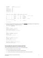
3. Verify that the PowerConnect B-DCX-4S is functioning correctly by typing switchShow or switchStatusShow.
This switchShow command displays PowerConnect B-DCX-4S and port status information.
switch:admin> switchshow
switchName:
switch
switchType:
62.1
switchState:
Online
switchMode:
Native
switchRole:
Subordinate
switchDomain:
11
10
PowerConnect B-DCX-4S Chassis Replacement Procedure
53-1001800-01
switchId:
switchWwn:
zoning:
switchBeacon:
blade3 Beacon:
blade5 Beacon:
blade8 Beacon:
blade10Beacon:
fffc0b
10:00:00:05:1e:39:59:67
OFF
OFF
OFF
OFF
OFF
OFF
Index Slot
Port
Address
Media Speed State Proto
===========================================================
32
3
0
0b2000
id
N4
Online
L-Port 5 public
33
3
1
0b2100
__
N8
No_Module
34
3
2
0b2200
__
N8
No_Module
35
3
3
0b2300
__
N8
No_Module
36
3
4
0b2400
id
N4
Online
F-Port
10:00:00:00:c9:51:00:2d
37
3
5
0b2500
__
N8
No_Module
switch:admin>
4. Verify that all the IP address information is correct by typing ipAddrShow and checking the results against the IP
information recorded in the “config-miscinfo.txt” file.
switch:admin> ipaddrshow
SWITCH
Ethernet IP Address: 10.32.50.12
Ethernet Subnetmask: 255.55.0.0
Fibre Channel IP Address: 1.2.3.4
Fibre Channel Subnetmask: 255.255.255.0
CP0
Ethernet IP Address: 10.32.50.10
Ethernet Subnetmask: 255.55.0.0
HostName : cp0
Gateway Address: 10.32.40.1
CP1
Ethernet IP Address: 10.32.50.11
Ethernet Subnetmask: 255.55.0.0
HostName : cp1
Gateway Address: 10.32.40.1
Backplane IP address of CP0 : 10.0.0.4
Backplane IP address of CP1 : 10.0.0.5
switch:admin>switch:admin>
Reconnecting the system to the network and fabric
See the cable routing information recorded in Table 2 for the following steps.
1. Connect the CP blades to the local area network:
a.
Insert the appropriate Ethernet cables into each Ethernet port.
b.
Connect the other ends to an Ethernet 10/100 Base-T LAN, if not already connected.
PowerConnect B-DCX-4S Chassis Replacement Procedure
53-1001800-01
11
NOTE
The PowerConnect B-DCX-4S can be accessed by remote connection using any of the available management
tools, such as Telnet or Web Tools. Ensure that the PowerConnect B-DCX-4S is not modified using other
connections during the rest of this procedure.
2. Reconnect the transceivers and cables to the port blades:
NOTE
The ports and cables used in trunking groups must meet specific requirements. For a list of these requirements,
refer to the Fabric OS Administrator’s Guide.
a.
Position one of the transceivers so that the key is oriented correctly to the port and insert the transceiver
into the port until it is firmly seated and the latching mechanism clicks.
b.
Select the cable that corresponds to the port and position it so that the key (the ridge on one side of the
cable connector) is aligned with the slot in the transceiver; then, insert the cable into the transceiver until
the latching mechanism clicks.
c.
Repeat step a and step b for the remaining ports.
ATTENTION
Do not route cables in front of the air exhaust vent (located on the upper port side of the chassis and
possibly the lower side if using the port side exhaust kit).
d.
Organize the cables as required.
Verifying correct configuration of the fabric
Copying the command outputs from this section into a file is recommended.
1. Create an “after” SAN profile by entering the following commands and copying the output to a text file named
“SANafter.txt”:
•
•
•
•
nsShow
nsAllShow
switchShow
fabricShow
switch:admin> nsshow
Type Pid
COS
PortName NodeName TTL(sec)
N
020f00;
3;10:00:00:01:73:00:29:46;10:00:00:01:73:00:29:46; na
Fabric Port Name: 20:0f:00:60:69:90:03:f0
<output truncated>
switch:admin> nsallshow
{020f00 021fda 021fdc 021fe0 021fe1
5 Nx_Ports in the Fabric}
switch:admin> switchshow
switchName: rsl8-st03-dcx-01
<output truncated>
switch:admin> fabricshow
Switch ID Worldwide Name Enet IP Addr FC IP Addr Name
<output truncated>
12
PowerConnect B-DCX-4S Chassis Replacement Procedure
53-1001800-01
switch:admin>
2. Determine any differences between the information in the “SANafter.txt” file and the information in the
“SANbefor.txt” file created earlier. In particular, look for differences in the following:
•
•
•
•
Device types
Number of devices
ISL and port states
Number of switches in the fabric
3. Resolve any issues or unintentional changes to the PowerConnect B-DCX-4S or fabric.
• If there are any mechanical problems, try reseating the associated component.
• If the configuration information is not correct for the PowerConnect B-DCX-4S, modify as required. If
necessary, the configuration saved before the replacement can be downloaded using the configDownload
command.
The configDownload command can be entered through a Telnet or serial session, but the PowerConnect
B-DCX-4S must have an Ethernet connection to the server name or IP of the host for the download process
to complete. For more information, refer to the help configdownload command or the Fabric OS Command
Reference.
switch:admin> configdownload
Server Name or IP Address [host]: 123.123.123.123
User Name [None]: Admin24
File Name [config.txt]: config-switch.txt
Password: xxxxxxxx
download complete
switch:admin>
• If other issues exist, contact your support provider.
Cable routing table
Table 2 is a 48-port template for a cable-routing table. Expand the table for the number of ports in the PowerConnect
B-DCX-4S.
TABLE 2
Cable routing table for PowerConnect B-DCX-4S (48 ports shown)
Slot/port
Slot
Cable labels
Port
Switch end
Connected device
Slot/port of device
Device end
0
1
2
3
4
5
6
7
PowerConnect B-DCX-4S Chassis Replacement Procedure
53-1001800-01
13
TABLE 2
Cable routing table for PowerConnect B-DCX-4S (48 ports shown) (Continued)
Slot/port
Slot
Cable labels
Port
Switch end
Connected device
Slot/port of device
Device end
8
9
10
11
12
13
14
15
16
17
18
19
20
21
22
23
24
25
26
27
28
29
30
31
32
33
34
35
36
37
38
39
40
41
42
14
PowerConnect B-DCX-4S Chassis Replacement Procedure
53-1001800-01
TABLE 2
Cable routing table for PowerConnect B-DCX-4S (48 ports shown) (Continued)
Slot/port
Slot
Cable labels
Port
Switch end
Connected device
Slot/port of device
Device end
43
44
45
46
47
Powering on the PowerConnect B-DX-4S
DANGER
Use the supplied power cords. Ensure the facility power receptacle is the correct type, supplies the
required voltage, and is properly grounded. (D004)
1. Connect the two AC power cords to each of the two power supplies.
2. Connect the power cords to a power source with a voltage of 200 to 240 VAC, 47 to 63 Hz.
3. Turn the AC power switches on the power supplies to ON. The AC power switches light green when switched on
and power is supplied.
4. The PowerConnect B-DCX-4S performs a power-on self-test (POST) each time it is powered on. POST takes
approximately ten minutes and is complete when the indicator light activity displays the operational state. For
information about LED patterns, see the PowerConnect B-DCX-4S Backbone Hardware Reference Manual.
You can bypass POST by using the fastBoot command. You can also disable POST for successive reboots on the
PowerConnect B-DCX-4S using the diagDisablePost command.
ATTENTION
Do not connect the switch to the network until the IP addresses are configured.
PowerConnect B-DCX-4S Chassis Replacement Procedure
53-1001800-01
15
16
PowerConnect B-DCX-4S Chassis Replacement Procedure
53-1001800-01