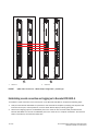
1
53-1002178-01
29 April 2011
®
Brocade DCX 8510-4
Backbone
QuickStart Guide
53-1002178-01
*53-1002178-01*
Copyright © 2011, Brocade Communications Systems, Incorporated.
Brocade, the B-wing symbol, BigIron, DCFM, DCX, Fabric OS, FastIron, IronView, NetIron, SAN Health, ServerIron, TurboIron, and Wingspan are
registered trademarks, and Brocade Assurance, Brocade NET Health, Brocade One, Extraordinary Networks, MyBrocade, VCS, and VDX are
trademarks of Brocade Communications Systems, Inc., in the United States and/or in other countries. Other brands, products, or service names
mentioned are or may be trademarks or service marks of their respective owners.
Notice: This document is for informational purposes only and does not set forth any warranty, expressed or implied, concerning any equipment,
equipment feature, or service offered or to be offered by Brocade. Brocade reserves the right to make changes to this document at any time,
without notice, and assumes no responsibility for its use. This informational document describes features that may not be currently available.
Contact a Brocade sales office for information on feature and product availability. Export of technical data contained in this document may
require an export license from the United States government.
The authors and Brocade Communications Systems, Inc. shall have no liability or responsibility to any person or entity with respect to any loss,
cost, liability, or damages arising from the information contained in this book or the computer programs that accompany it.
The product described by this document may contain “open source” software covered by the GNU General Public License or other open source
license agreements. To find out which open source software is included in Brocade products, view the licensing terms applicable to the open
source software, and obtain a copy of the programming source code, please visit
http://www.brocade.com/support/oscd.
Brocade Communications Systems, Incorporated
Corporate and Latin American Headquarters
Brocade Communications Systems, Inc.
130 Holger Way
San Jose, CA 95134
Tel: 1-408-333-8000
Fax: 1-408-333-8101
E-mail: [email protected]
Asia-Pacific Headquarters
Brocade Communications Systems China HK, Ltd.
No. 1 Guanghua Road
Chao Yang District
Units 2718 and 2818
Beijing 100020, China
Tel: +8610 6588 8888
Fax: +8610 6588 9999
E-mail: [email protected]
European Headquarters
Brocade Communications Switzerland Sàrl
Centre Swissair
Tour B - 4ème étage
29, Route de l'Aéroport
Case Postale 105
CH-1215 Genève 15
Switzerland
Tel: +41 22 799 5640
Fax: +41 22 799 5641
E-mail: [email protected]
Asia-Pacific Headquarters
Brocade Communications Systems Co., Ltd. (Shenzhen WFOE)
Citic Plaza
No. 233 Tian He Road North
Unit 1308 – 13th Floor
Guangzhou, China
Tel: +8620 3891 2000
Fax: +8620 3891 2111
E-mail: [email protected]
Document History
Document Title
Publication
Number
Summary of
Changes
Publication
Date
Brocade DCX 8510-4 Backbone
QuickStart Guide
53-1002178-01
New document.
April 2011
2 of 24
Brocade DCX 8510-4 Backbone QuickStart Guide
Publication Number: 53-1002178-01
In this guide
• Introduction. . . . . . . . . . . . . . . . . . . . . . . . . . . . . . . . . . . . . . . . . . . . . . . . . . . .
• Safety notices . . . . . . . . . . . . . . . . . . . . . . . . . . . . . . . . . . . . . . . . . . . . . . . . . .
• Brocade DCX 8510-4, port side. . . . . . . . . . . . . . . . . . . . . . . . . . . . . . . . . . . .
• Brocade DCX 8510-4, nonport side . . . . . . . . . . . . . . . . . . . . . . . . . . . . . . . .
• Time and items required for installation. . . . . . . . . . . . . . . . . . . . . . . . . . . . .
• Site planning and safety guidelines . . . . . . . . . . . . . . . . . . . . . . . . . . . . . . . .
• Items included with the Brocade DCX 8510-4 . . . . . . . . . . . . . . . . . . . . . . .
• Unpacking and installing the Brocade DCX 8510-4. . . . . . . . . . . . . . . . . . .
• Providing power to the Brocade DCX 8510-4 . . . . . . . . . . . . . . . . . . . . . . . .
• Managing cables . . . . . . . . . . . . . . . . . . . . . . . . . . . . . . . . . . . . . . . . . . . . . .
• Installing QSFP cables (optional). . . . . . . . . . . . . . . . . . . . . . . . . . . . . . . . . .
• Establishing a serial connection and logging on to Brocade DCX 8510-4 .
• Configuring IP addresses . . . . . . . . . . . . . . . . . . . . . . . . . . . . . . . . . . . . . . . .
• Establishing an Ethernet connection . . . . . . . . . . . . . . . . . . . . . . . . . . . . . .
• Customizing a switch name . . . . . . . . . . . . . . . . . . . . . . . . . . . . . . . . . . . . . .
• Customizing a chassis name . . . . . . . . . . . . . . . . . . . . . . . . . . . . . . . . . . . . .
• Setting the Domain ID . . . . . . . . . . . . . . . . . . . . . . . . . . . . . . . . . . . . . . . . . .
• Verifying PID mode . . . . . . . . . . . . . . . . . . . . . . . . . . . . . . . . . . . . . . . . . . . . .
• Confirming software licenses . . . . . . . . . . . . . . . . . . . . . . . . . . . . . . . . . . . .
• Backing up the configuration . . . . . . . . . . . . . . . . . . . . . . . . . . . . . . . . . . . .
3
4
4
6
7
8
10
10
11
12
14
16
18
19
19
20
20
21
23
23
Introduction
This guide provides instructions for unpacking, installing, and setting up a Brocade DCX 8510-4 as a standalone unit
quickly. Note the following additional documentation:
• For detailed installation and configuration instructions, refer to the Brocade DCX 8510-4 Backbone Hardware
Reference Manual.
• For rack-specific installation instructions, refer to the appropriate rack mount or mid-mount installation
procedures.
The Brocade DCX 8510-4 can be installed in the following ways:
• As a standalone unit on a flat surface.
• In a chassis with the Port Side Exhaust Kit (provided) in a Brocade-qualified rack.
• In a 19-in. Electronic Industries Association (EIA) cabinet, using a Brocade 8510-4, DCX-4S Rack Mount Kit
(either a 27-31 in. or 18-34 in. kit depending on rack used).
• In a mid-mount telecommunications (Telco) rack, using the Brocade 8510-4, DCX-4S Mid-Mount Rack Kit
available from your Brocade DCX 8510-4 supplier (optional).
The basic configuration steps required to set up the Brocade DCX 8510-4 Backbone are listed in this guide.
Additional configuration information is provided in the Brocade DCX 8510-4 Backbone Hardware Reference Manual
and the Fabric OS Administrator’s Guide.
Brocade DCX 8510-4 Backbone QuickStart Guide
Publication Number: 53-1002178-01
3 of 24
ATTENTION
In order to comply with EMI certification, the door of the Brocade DCX 8510-4 must be installed. It is also
recommended that the rubber port plugs be installed in the core blade QSFP sockets if QSFP cables are not used.
Safety notices
When using this product, observe the danger, caution, and attention notices in this manual. The notices are
accompanied by symbols that represent the severity of the safety condition.
NOTE
Translated safety notices are in the Brocade Product Safety Notices publication, which is on the CD-ROM that
accompanies this product.
The danger and caution notices are listed in numerical order based on their IDs, which are displayed in parentheses,
for example (D004), at the end of each notice. Use this ID to locate the translations of these danger and caution
notices in the Brocade Product Safety Notices.
Danger notices
A danger notice calls attention to a situation that is potentially lethal or extremely hazardous to people. A
lightning bolt symbol accompanies a danger notice to represent a dangerous electrical condition. Read and
comply with the following danger notice before installing or servicing this device.
DANGER
Use the supplied power cords. Ensure the facility power receptacle is the correct type, supplies the
required voltage, and is properly grounded. (D004)
Caution notices
A caution notice calls attention to a situation that is potentially hazardous to people because of some existing
condition. Read and comply with the following caution notice before installing or servicing this device.
CAUTION
Use safe lifting practices when moving the product. (C015)
Brocade DCX 8510-4, port side
The following figure shows a sample configuration of the port side of the Brocade DCX 8510-4.
NOTE
Airflow for the Brocade DCX 8510-4 is from the nonport (non-cable) side to the left-hand side of the chassis as you
look from the port side. If you use the Port Side Exhaust Kit the air vents are on the port side of the chassis.
4 of 24
Brocade DCX 8510-4 Backbone QuickStart Guide
Publication Number: 53-1002178-01
1
2
3
4
1
FC16-48 port blade (example, 4x)
3
Control processor blade (CP8) (2x)
2
Core switch blade (CR16-4) (2x)
4
Exhaust vent
FIGURE 1
Port side of the Brocade DCX 8510-4 (sample configuration)
Brocade DCX 8510-4 Backbone QuickStart Guide
Publication Number: 53-1002178-01
5 of 24
FIGURE 2
Port side of the Brocade DCX 8510-4 with the port side exhaust kit installed (sample configuration)
Brocade DCX 8510-4, nonport side
The following figure shows a sample configuration of the nonport side view of the Brocade DCX 8510-4.
6 of 24
Brocade DCX 8510-4 Backbone QuickStart Guide
Publication Number: 53-1002178-01
1
2
3
4
1
WWN card bezel (logo plate - WWN card behind)
2
Power supply (2x)
3
Blower assembly (2x)
4
Label with serial number and WWN
FIGURE 3
Nonport side of the Brocade DCX 8510-4 (sample configuration)
Time and items required for installation
You can set up and install the Brocade DCX 8510-4 in the following ways:
• As a standalone unit on a flat surface.
• In a 19-in. Electronic Industries Association (EIA) cabinet, using a Brocade DCX 8510-4, DCX-4S Rack Mount Kit
(either a 27-31 in. or 18-34 in. kit depending on rack used).
• In a chassis with the Port Side Exhaust Kit (provided) in a Brocade-qualified rack.
• In a mid-mount telecommunications (Telco) rack, using the Mid-Mount Rack Kit available from your Brocade DCX
8510-4 supplier.
This chapter describes how to set up the Brocade DCX 8510-4 as a standalone unit. For rack-mount installation
instructions, refer to the appropriate manual as described in the following table.
The following table describes the main installation and setup tasks, the estimated time required for each, and the
items required to complete the task based on a fully populated Brocade DCX 8510-4 (192 Fibre Channel ports using
the FC16-48 port blades). Configurations with fewer ports require less time. These time estimates assume a
prepared installation site and appropriate power and network connectivity.
Brocade DCX 8510-4 Backbone QuickStart Guide
Publication Number: 53-1002178-01
7 of 24
TABLE 1
Installation tasks, time, and items required
Installation task
Time estimate
Items required
Site preparation and unpacking Brocade
DCX 8510-4
30 minutes
1/2-in. socket wrench (to remove pallet bolts).
#2 Phillips screwdriver
(for cable management comb).
Pallet jack.
Hydraulic lift or assisted lift, able to raise to a
minimum of 140 cm (55 in.), with a minimum
capacity of 113 kg (250 lb). The Brocade DCX
8510-4 weighs 68 kg (150 lb) with four
FC16-48 port cards installed (192 ports).
Installing rack mount kit or
port side exhaust kit
30 minutes
Mounting and securing Brocade DCX
8510-4 in rack
30 minutes
Refer to the one or more of the following if you
are mounting the Brocade DCX 8510-4 in a
rack:
Brocade Port Side Exhaust Kit Installation
Procedure
Brocade DCX 8510-4, DCX-4S Mid-Mount Rack
Kit Installation Procedure or
Brocade DCX 8510-4, DCX-4S Rack Kit
Installation Procedure.
Installing power cables and powering on
the Brocade DCX 8510-4
20 minutes
Power cables (provided in the Brocade DCX
8510-4 accessory kit).
Establishing serial connection, logging on
to Brocade DCX 8510-4, and configuring IP
addresses
20 minutes
Serial cable (provided in the accessory kit).
Workstation computer with a serial port or
terminal server port and a terminal emulator
application (such as HyperTerminal).
Ethernet IP addresses for the Brocade DCX
8510-4 chassis and for both control processor
blades: total three addresses.
Installing an Ethernet cable, opening a
Telnet session, and configuring the
Brocade DCX 8510-4 domain ID, date and
time, and additional system parameters.
Verify and back up configuration.
20 minutes
Ethernet cabling (optional) for Telnet access.
Refer to the Fabric OS Administrator’s Guide.
Installing transceivers as needed
20 minutes (longer
if using high-density
port blades)
SFP+, mSFP, and QSFP optical transceivers as
needed.
Attaching fiber optic cables, cable ties, and
cable guides
2-3 hours
Fiber optic cables, cable ties, and cable comb.
Site planning and safety guidelines
NOTE
Read the safety notices before installation (“Safety notices”).
Read “Power specifications” in the Brocade DCX 8510-4 Hardware Reference Manual appendix to plan for meeting
power supply standards before installing the chassis.
Read “Managing cables” to plan for cable management.
8 of 24
Brocade DCX 8510-4 Backbone QuickStart Guide
Publication Number: 53-1002178-01
The following steps are required to ensure correct installation and operation.
1. Provide a space that is 9 rack units (9U) high, 61.19 cm (24.09 in.) deep, and 43.74 cm (17.22 in.) wide. 1U is
equal to 4.45 cm (1.75 in.). If you do not use the provided port side exhaust kit, the space needs to be only 8
rack units (8U) high.
Plan to install the Brocade DCX 8510-4 with the nonport side facing the air-intake aisle. The Brocade DCX
8510-4 can be installed facing either direction, if serviceability and cooling requirements are met.
2. Ensure that dedicated electrical branch circuits with the following characteristics are available:
NOTE
See “Power specifications” in the “Specifications” appendix for specific requirements depending on your
chassis configuration.
• 200 – 240 VAC, 50–60 Hz (two branch circuits) - recommended for high availability and maximum blade
usage
•
•
•
•
•
Two cables for 200 - 240 VAC service
Protected by a circuit breaker in accordance with local electrical codes
Supply circuit, line fusing, and wire size adequate to the electrical rating on the chassis nameplate
Location close to the chassis and easily accessible
Grounded outlets installed by a licensed electrician and compatible with the power cords
ATTENTION
To maximize fault tolerance, connect each power cord to a separate power source.
3. Plan for cable management before installing the chassis.
Cables can be managed in a variety of ways, such as by routing cables below the chassis, to either side of the
chassis, through cable channels on the sides of the cabinet, or by using patch panels.
4. Ensure that the following is available for configuration of the Brocade DCX 8510-4:
•
•
•
•
Workstation with an installed terminal emulator, such as HyperTerminal
Serial cable (provided)
Three Ethernet cables (including one spare)
Access to an FTP server for backing up the switch configuration or collecting supportsave output data
(optional)
• A Brocade USB stick for collecting supportsave output data (optional)
• Transceivers (copper and optical) and compatible cables
NOTE
For information about the transceivers that are qualified for the Brocade DCX 8510-4, go to
http://www.brocade.com/products/interop_and_compatibility.jsp.
5. Ensure that the air intake and exhaust vents have a minimum of two (2) inches of airspace.
6. Ensure that the air temperature on the air intake side is less than 40 degrees Celsius (104 degrees Fahrenheit)
during operation.
Brocade DCX 8510-4 Backbone QuickStart Guide
Publication Number: 53-1002178-01
9 of 24
Items included with the Brocade DCX 8510-4
The Brocade DCX 8510-4 ships with the following:
• Brocade DCX 8510-4 chassis, populated with:
- Control processor blades (CP8)
- Core switch blades (CR16-4)
- Port blades, application blades, and encryption blades (included based on customer specification)
- Blade slot filler panels (for slots not filled by blades)
- Port side exhaust kit (included based on customer specification)
- WWN cards
- WWN bezel (logo plate)
- Power supplies
- Power supply filler panel (included if there is only one power supply)
- Blower assemblies
- Cable management finger assemblies
- Chassis door
• Accessory kit containing the following items:
- Brocade DCX 8510-4 Backbone QuickStart Guide
- Brocade Documentation CD (contains documents related to the Brocade DCX 8510-4)
- ESD grounding strap
- USB device
- RS-232 serial cable. The RS-232 cable has an adapter at one end that can be removed to provide an
RJ-45-style connector.
• Brocade DCX 8510-4, DCX-4S rack mount kit with instructions
Order the optical transceivers (SFP+, mSFP, and QSFP) from Brocade. The Brocade DCX 8510-4 supports SWL, LWL,
and ELWL transceivers. The mSFPs and QSFPs are SWL transceivers only.
NOTE
For information about the SFP+, mSFP, and QSFP transceivers that are qualified for the Brocade DCX 8510-4, go to
http://www.brocade.com/products/interop_and_compatibility.jsp.
Unpacking and installing the Brocade DCX 8510-4
Use the following procedure to unpack and install your Brocade DCX 8510-4.
CAUTION
Use safe lifting practices when moving the product. (C015)
10 of 24
Brocade DCX 8510-4 Backbone QuickStart Guide
Publication Number: 53-1002178-01
NOTE
A fully populated Brocade DCX 8510-4 (four FC16-48 port cards, 192 ports) weighs approximately 68 kg (150 lbs) and
requires a hydraulic or assisted lift to install it.
1. Unpack the Brocade DCX 8510-4.
a.
Cut the bands that encircle the packaging.
b.
Remove the lid and the kits and foam from the top of the chassis.
c.
Lift the cardboard box off the chassis and remove the plastic bag from around the chassis.
Save the packing materials for use when returning the old chassis.
d.
Leave the chassis on top of the plastic shipping tray if the chassis must be transported to the installation
location.
NOTE
The Brocade DCX 8510-4 packaging does not incorporate a wood pallet and pallet brackets. The chassis sits on
top of a plastic shipping tray.
2. Use a pallet jack or other assisted lift to transport the new chassis to the installation area. Doorways must be
wider than 36 in. (91 cm) to accommodate the chassis.
3. Remove the Brocade DCX 8510-4 port side exhaust kit (if ordered), accessory kit, packing foam, and antistatic
plastic from the chassis and set aside.
4. Remove the chassis door from the Brocade DCX 8510-4.
5. Remove the vertical cable management fingers.
6. Use a lift to raise the chassis to the correct level. If installing the chassis in a cabinet, follow the instructions
provided by the rack kit manufacturer.
7.
If applicable, lock the wheels of the lift.
8. Gently slide the chassis onto the final installation surface, ensuring that it remains supported during the
transfer.
9. Ensure that the chassis is oriented so that the nonport side has access to intake air (cool).
10. Reinstall the vertical cable management fingers.
11. Reinstall the door. The door must be installed to meet EMI compliance.
Providing power to the Brocade DCX 8510-4
Complete the following steps to provide power to the chassis.
DANGER
Use the supplied power cords. Ensure the facility power receptacle is the correct type, supplies the
required voltage, and is properly grounded. (D004)
Brocade DCX 8510-4 Backbone QuickStart Guide
Publication Number: 53-1002178-01
11 of 24
1. Connect the two AC power cords to the two power supplies.
2. Connect the power cords to a power source with voltage of 200 to 240 VAC, 47 to 63 Hz or optionally to a power
source with voltage of 110 to 120 VAC, 47 to 63 Hz. If using any application blades in the chassis, the 200 to
240 VAC option is necessary in order to achieve power supply redundancy.
ATTENTION
Use of the high-voltage line (200 to 240 VAC) is highly recommended because of better power-conversion
efficiency.
For a fully-loaded DCX 8510-4 or DCX-4S, 200 to 240 VAC is required for high availability (ability to hot swap a
failed power supply without affecting system operation.
3. Turn the AC power switches on the power supplies to I. The AC power switches light green when switched on and
power is supplied.
4. The Brocade DCX 8510-4 performs a power-on self-test (POST) each time it is powered on. POST takes
approximately 10 minutes and is complete when the indicator light activity displays the operational state.
You can bypass POST by using the fastBoot command. You can also disable POST for successive reboots on the
Brocade DCX 8510-4 using the diagDisablePost command.
ATTENTION
Do not connect the switch to the network until the IP addresses are configured.
Managing cables
The vertical cable management fingers are attached to the rack to either side of the chassis door and allow for
simple cable management. The fingers can be installed without service disruption.
Route the cables along the front of the blades to keep LEDs visible. Leave at least one meter of slack for each fiber
optic cable to provide room to remove and replace blades.
ATTENTION
The minimum bend radius for a 50 micron cable is 2 in. under full tensile load and 1.2 in. with no tensile load.
Cables can be organized and managed in a variety of ways, for example, using cable channels on the sides of the
cabinet or patch panels to minimize cable management. Following is a list of recommendations:
NOTE
You should not use tie wraps with optical cables because they are easily overtightened and can damage the optic
fibers.
• Plan for rack space required for cable management before installing the switch.
• Leave at least 1 m (3.28 ft) of slack for each port cable. This provides room to remove and replace the
switch, allows for inadvertent movement of the rack, and helps prevent the cables from being bent to less
than the minimum bend radius.
• If you are using Brocade ISL Trunking, consider grouping cables by trunking groups. The cables used in
trunking groups must meet specific requirements, as described in the Fabric OS Administrator’s Guide.
• For easier maintenance, label the fiber optic cables and record the devices to which they are connected.
• Keep LEDs visible by routing port cables and other cables away from the LEDs.
• Use Velcro® type straps to secure and organize fiber optic cables.
12 of 24
Brocade DCX 8510-4 Backbone QuickStart Guide
Publication Number: 53-1002178-01
ATTENTION
Do not route the cables in front of the air exhaust vent, which is located at the top of the port side of the chassis.If
you are using the Port Side Exhaust Kit with your Brocade DCX 8510-4, there is also an exhaust vent at the bottom of
the port side of the chassis. Use the vertical cable fingers to keep the cables away from this exhaust vent as well.
FIGURE 4
Vertical cable management finger assemblies
High density cabling
The FC8-64 high density port blade cannot use the standard LC cables because the pitch between optics in the new
mini-SFP (mSFP) transceiver is smaller than in standard SFPs. Patch cables and panels can be used to attach
standard size cabling to the blade if necessary. The figure below illustrates the mSFP to SFP patch cable. See “Best
Practices Guide: High Density Cable Management Solutions” (available at http://www.brocade.com) for cable
management guidelines for high-density port solutions, cable and patch panel part numbers.
2
3
mSFP connector
Duplex clip (black)
3
4
4
1
1
2
FIGURE 5
1.6 mm cable
SFP connector
Cable design for the mSFP patch cables for the FC8-64 high density port blade
Brocade DCX 8510-4 Backbone QuickStart Guide
Publication Number: 53-1002178-01
13 of 24
Please note that the duplex clip on the mSFP end of the cable is black for easier recognition. See the appendix for a
listing of the qualified mSFP optical cables for the FC8-64 port blade.
If ISL Trunking is in use, group the cables by trunking group. The ports are color-coded to indicate which ports can be
used in the same ISL Trunking group: eight ports marked with solid black ovals alternate with eight ports marked
with oval outlines. See the appendix for a listing of supported cable speeds and distances.
Installing QSFP cables (optional)
Use this procedure to remove and replace a QSFP cable.
NOTE
The QSFP ports can be used only with an inter-chassis link (ICL) license. After the addition or removal of a license, the
license enforcement is performed on the ports only when the portdisable and portenable commands are issued on
the ports. An ICL license must be installed on all Brocade Backbones forming the ICL connection. Up to five
neighboring Brocade 8510 series chassis can be combined with the QSFP cables.
NOTE
For the Brocade 8510 Backbones, an off-the-shelf QSFP cable up to 50 meters long can be used as an ICL cable.
ATTENTION
For the 8510 series models, if the QSFP cables are not used, make sure the rubber gaskets are in the QSFP
transceivers.
The following table describes the connector port LED patterns and the recommended actions for those patterns.
TABLE 2
QSFP connector port LEDs
LED purpose
Color
Status
Recommended action
QSFP
connector
status
No light (LED is off)
No QSFP module, all four
QSFP ports are disabled
No action required if QSFP no
present or
verify that the QSFP is fully inserted.
Steady amber
QSFP module is in, all four
ports have no signal/no
sync.
No action required if QSFP only is
installed or
ensure that the cable is properly
connected. If the LED remains
amber, consult the Brocade DCX
8510-4 supplier.
Blinking amber
Port is disabled or faulted,
FC link activity, segmented,
loopback mode, also
during transition between
QSFP cable insertion and
confirmation.
Check for console messages or wait
for all four ports to come online.
Steady green
Both ends of QSFP cable
are in and all ports are
online. Fulll link is
established.
No action required.
Follow this procedure to install the QSFP cables. Refer to the Fabric OS Administrator’s Guide for the configuration
procedure and requirements.
14 of 24
Brocade DCX 8510-4 Backbone QuickStart Guide
Publication Number: 53-1002178-01
The figure below shows an QSFP cable and transceiver. The QSFP connectors on the core blades are labeled by
trunk group (trunking is optional) for ease of installation. The subsequent figures shows acceptable cabling
configurations for the ICL feature. The recommended topology is the parallel type where there are four QSFP cables
connected between any pair of Brocade 8510 series chassis.The full mesh configuration is also supported.
FIGURE 6
QSFP cable and transceiver
Installing a QSFP cable
Complete the following steps to replace a QSFP cable.
1. If the QSFP transceiver is being replaced, grasp the bail of the new QSFP and push the QSFP into the connector
on the blade until it is firmly seated. The QSFP is keyed to fit into the connector in one way. The status LED
initially blinks amber after installation, then displays steady amber.
2. Grasp the QSFP cable by the rubber housing and push it into the QSFP transceiver until it is firmly seated. The
cable housing is keyed to fit into the QSFP in one way.
The status LED displays steady amber until both ends of the cable are inserted and the link is established.
When the link is fully established, the LED displays steady green.
3. Repeat for each cable that requires replacement.
4. Once all the cables are attached, see the Fabric OS Administrator’s Guide for the configuration procedure.
Possible QSFP cable configurations
The following figure illustrates one possible QSFP cable configuration between two 8510 series chassis. Up to five
neighboring 8510 chassis can be connected as long as each of two cores in one chassis is interconnected with each
of two cores in the next chassis. This provides for inter-chassis link (ICL) trunking between chassis, ensuring
redundancy. Parallel connections between core blades are recommended, but both parallel and mesh cable
arrangements are supported.
Brocade DCX 8510-4 Backbone QuickStart Guide
Publication Number: 53-1002178-01
15 of 24
1
1
Chassis 1
FIGURE 7
2
2
Chassis 2
QSFP cable connections – 8510 sample configuration - parallel type
Establishing a serial connection and logging on to Brocade DCX 8510-4
To establish a serial connection to the console port on the Brocade DCX 8510-4, complete the following steps.
1. Verify that the Brocade DCX 8510-4 is powered on and that POST is complete by verifying that all power LED
indicators on the port, control processor, and core switch blades display a steady green light.
2. Remove the shipping cap from the CONSOLE port on the active CP. Use the serial cable provided with the
Brocade DCX 8510-4 to connect the CONSOLE port on the active CP to a computer workstation. The active CP
blade is indicated by an illuminated (blue) LED.
16 of 24
Brocade DCX 8510-4 Backbone QuickStart Guide
Publication Number: 53-1002178-01
ATTENTION
The CONSOLE port is intended primarily for the initial setting of the IP address and for service purposes.
3. Access the Brocade DCX 8510-4 using a terminal emulator application (such as HyperTerminal in a Windows
environment or tip in a UNIX environment).
4. Disable any serial communication programs running on the workstation (such as synchronization programs).
5. Open a terminal emulator application (such as HyperTerminal on a PC, or term, tip, or kermit in a UNIX
environment), and configure the application as follows:
• In a Windows environment:
Parameter
Value
Bits per second
9600
Data bits
8
Parity
None
Stop bits
1
Flow control
None
• In a UNIX environment, enter the following string at the prompt:
tip /dev/ttyb -9600
If ttyb is already in use, use ttya instead and enter the following string at the prompt:
tip /dev/ttya -9600
When the terminal emulator application stops reporting information, press Enter. You receive the following login
prompt:
CP0 Console Login:
6. Proceed to the next task.
Logging on to the Brocade DCX 8510-4
To log in to the Brocade DCX 8510-4 through the serial connection, follow these steps.
1. Log in to the Brocade DCX 8510-4 as admin. The default password is password. At the initial login, you are
prompted to enter new admin and user passwords. Make sure to write down the new passwords and keep this
information in a secure location.
Fabric OS (swDir)
swDir login: admin
Password:
Please change your passwords now.
Use Control-C to exit or press 'Enter' key to proceed.
swDir:admin>
Brocade DCX 8510-4 Backbone QuickStart Guide
Publication Number: 53-1002178-01
17 of 24
2. (Optional) Modify passwords. To skip modifying the password, press Ctrl-C. For more information on passwords,
refer to the Fabric OS Administrator’s Guide.
NOTE
Passwords can be 8 to 40 characters long. They must begin with an alphabetic character. They can include
numeric characters, the dot (.), and the underscore (_) only. Passwords are case-sensitive, and they are not
displayed when you enter them on the command line.
For more information on passwords, refer to the Fabric OS Administrator’s Guide.
Configuring IP addresses
The Brocade DCX 8510-4 requires three IP addresses, which are configured using the ipAddrSet command. IP
addresses are required for both CP blades (CP0 and CP1) and for the chassis management IP (shown as SWITCH
under the ipAddrShow command) in the Brocade DCX 8510-4.
NOTE
The default IP addresses and host names for the Brocade DCX 8510-4 are:
– 10.77.77.75 / CP0 (the CP blade in slot 6 at the time of configuration)
– 10.77.77.74 / CP1 (the CP blade in slot 7 at the time of configuration)
ATTENTION
Resetting an IP address while the Brocade DCX 8510-4 has active IP traffic or has management and monitoring tools
running, such as DCFM, Fabric Watch, and SNMP, can cause traffic to be interrupted or stopped.
Complete the following steps to set the IP addresses for the Brocade DCX 8510-4.
1. Log in to the active CP as admin using the serial cable connection.
2. Set up the Brocade DCX 8510-4 IP address by entering the ipaddrset -chassis command:
swDir:admin> ipAddrSet -chassis
Enter the information at the prompts. Specify the -chassis IP address. The -sw 0 IP address is not valid on this
chassis.
NOTE
The addresses 10.0.0.0 through 10.0.0.255 are reserved and used internally by the Brocade DCX 8510-4.
External IPs must not use these addresses.
3. Set up the CP0 IP address by entering the ipaddrset -cp 0 command:
swDir:admin> ipAddrSet -cp 0
Enter the information at the prompts.
4. Set up the CP1 IP address by entering the ipaddrset -cp 1 command:
swDir:admin> ipAddrSet -cp 1
Enter the information at the prompts.
This is a sample IP configuration:
swDir:admin> ipaddrset -chassis
Ethernet IP Address [0.0.0.0]: 123.123.123.120
18 of 24
Brocade DCX 8510-4 Backbone QuickStart Guide
Publication Number: 53-1002178-01
Ethernet Subnetmask [0.0.0.0]: 123.123.123.123
Fibre Channel IP Address [0.0.0.0]:
Fibre Channel Subnetmask [0.0.0.0]:
Issuing gratuitous ARP...Done.
Committing configuration...Done.
swDir:admin> ipaddrset -cp 0
Host Name [cp0]:
Ethernet IP Address [10.77.77.75]: 123.123.123.121
Ethernet Subnetmask [0.0.0.0]: 123.123.123.123
Gateway IP Address [0.0.0.0]: 123.123.123.124
IP address is being changed...Done.
Committing configuration...Done.
swDir:admin> ipaddrset -cp 1
Host Name [cp1]:
Ethernet IP Address [10.77.77.74]: 123.123.123.122
Ethernet Subnetmask [0.0.0.0]: 123.123.123.123
Gateway IP Address [0.0.0.0]: 123.123.123.124
IP address of remote CP is being changed...Done.
Committing configuration...Done.
Establishing an Ethernet connection
NOTE
Connecting the CP blades to a private network/VLAN is recommended.
After using a serial connection to configure the IP addresses for the Brocade DCX 8510-4, you can connect the
active CP blade to the local area network (LAN).
By establishing an Ethernet connection, you can complete the Brocade DCX 8510-4 configuration using either a
serial session, Telnet, or management applications, such as Web Tools or Brocade Network Advisor.
Perform the following steps to establish an Ethernet connection to the Brocade DCX 8510-4.
1. Remove the shipping plug from the Ethernet port on the active CP blade.
2. Insert one end of an Ethernet cable into the Ethernet port.
3. Connect the other end to an Ethernet 10/100/1000 BaseT LAN.
The Brocade DCX 8510-4 can be accessed through a remote connection using the command line via Telnet or
any of the management tools, such as Web Tools or Brocade Network Advisor.
4. To complete any additional Brocade DCX 8510-4 configuration procedures through a Telnet session, log in to the
Brocade DCX 8510-4 by Telnet, using the admin login. The default password is password.
Customizing a switch name
The switch name of the Brocade DCX 8510-4 can be up to 30 characters long using Fabric OS release 6.3.0 or later;
can include letters, numbers, hyphens, and underscore characters; and must begin with a letter.
Brocade DCX 8510-4 Backbone QuickStart Guide
Publication Number: 53-1002178-01
19 of 24
NOTE
Changing the name causes a domain address format RSCN to be issued.
1. Type switchName followed by the new name in double quotes.
swDir:admin> switchName "swModularSwitch5"
Committing configuration...
Done.
swModularSwitch5:admin>
2. Record the new name for reference.
Customizing a chassis name
The chassis name of the Brocade DCX 8510-4 can be up to 15 characters long; can include letters, numbers,
hyphens, and underscore characters; and must begin with a letter.
1. Enter chassisName followed by the new name in double quotes.
switch:admin> chassisname "DCX8510_chassis"
Committing configuration...
Done.
2. Enter chassisName by itself to show the name.
switch:admin> chassisname
DCX8510_chassis
3. Record the new name for reference.
Setting the Domain ID
Each switch in the fabric must have a unique domain ID. The domain ID can be manually set through the configure
command or can be automatically set. The default domain ID for the Brocade DCX 8510-4 is 1. Use the fabricShow
command to view the already assigned domain IDs.
1. Enter switchDisable to disable the Brocade DCX 8510-4.
2. Enter configure.
3. Enter y at the Fabric parameters prompt:
Fabric parameters (yes, y, no, n): [no] y
4. Enter a unique domain ID:
Domain: (1.239) [1] 3
5. Complete the remaining prompts or press Ctrl+D to accept the settings and exit.
6. Enter switchEnable to reenable the Brocade DCX 8510-4.
20 of 24
Brocade DCX 8510-4 Backbone QuickStart Guide
Publication Number: 53-1002178-01
Verifying PID mode
Before connecting the Brocade DCX 8510-4 to the fabric, verify that the port identifier (PID) mode on the Brocade
DCX 8510-4 matches the other switches in the fabric. This parameter must be identical for all switches in the fabric
and is set using the configure command.
Installing transceivers
Follow these steps to install SFP+s and mSFPs (FC8-64 port card only) and cables to the Brocade DCX 8510-4.
Follow the second set of steps to install the QSFP transceivers and cables in the core blades for inter-chassis link
connections.
NOTE
mSFP transceivers are compatible only with the FC8-64 port blade. While they will fit in other blades, this
configuration is unsupported and will generate an error.
The ports are color-coded to indicate which can be used in the same port group for trunking (trunking port groups
can be up to eight ports). The ports and cables used in trunking groups must meet specific requirements. Refer to
the Fabric OS Administrator’s Guide for more information.
1. Add the optical transceivers and cables to the Fibre Channel ports.
The ports are color-coded to indicate which can be used in the same port group for trunking (trunking port
groups can be up to 8 ports). The ports and cables used in trunking groups must meet specific requirements.
Refer to the Fabric OS Administrator’s Guide.
2. Position one of the optical transceivers so that the key is oriented correctly to the port. Insert the transceiver into
the port until it is firmly seated and the latching mechanism clicks.
Transceivers are keyed so that they can only be inserted with the correct orientation. If a transceiver does not
slide in easily, ensure that it is correctly oriented.
3. Position a cable so that the key (the ridge on one side of the cable connector) is aligned with the slot in the
transceiver. Insert the cable into the transceiver until the latching mechanism clicks.
Cables are keyed so that they can be inserted in only one way. If a cable does not slide in easily, ensure that it is
correctly oriented.
4. Repeat steps 1 through 3 for the remaining ports.
5. Organize the cables See “Managing Cables.”
6. Verify the Brocade DCX 8510-4 and port status using the switchShow command.
7.
Verify fabric connectivity using the fabricShow command.
Follow these steps to install the QSFPs and cables in the 16 Gbps core blades. These transceivers and cables are
used to form the inter-chassis links (ICL) with neighboring DCX 8510 Backbones.
The transceivers should be installed in the blades before connecting the cables.
Because each QSFP contains four 16 Gbps ports, be aware that any problems with one port could affect all four
ports in the quad if the QSFP has to be replaced.
Brocade DCX 8510-4 Backbone QuickStart Guide
Publication Number: 53-1002178-01
21 of 24
1. Position one of the QSFP transceivers so that the key is oriented correctly to the port. Insert the transceiver into
the port until it is firmly seated.
Transceivers are keyed so that they can only be inserted with the correct orientation. If a transceiver does not
slide in easily, ensure that it is correctly oriented.
When the transceiver is correctly seated, the status LED will flash amber several times and then turn solid
amber.
2. Remove the protective cap from the special QSFP cable and insert it into the transceiver until it is firmly seated.
The cables are also keyed to fit into the transceivers correctly.
When the cable is correctly seated, the status LED will change from amber to green.
Repeat steps 1 and 2 for the remaining ICL
3. Organize the cables See “Managing Cables.”
4. Verify the Brocade DCX 8510-4 and connector and port status using the switchShow -qsfp command.
A sample of the command output is shown below. The example is from a DCX 8510-4 with a core blae installed
in slot 3. Some detials for the 8510-8 will be different, but the reported information for the QSFPs will be similar.
Note that the State reported for an unconnected QSFP (shown QSFP 0 and Ports 0-3 below) is No_SigDet. This is
different from the State of No_Synch that is reported for regular SFPs that are unconnected.
QSFP 7 (ports 3/28-3/31, Index 748-751) in the following example shows the results for a connected QSFP.
switch:FID128:admin> switchshow -qsfp
switchName:
switch name
switchType:
121.3
switchState:
Online
switchMode:
Native
switchRole:
Subordinate
switchDomain:
75
switchId:
fffc4b
switchWwn:
10:00:00:05:1e:4f:eb:00
zoning:
ON (zoning name)
switchBeacon:
OFF
FC Router:
OFF
Allow XISL Use: OFF
LS Attributes: [FID: 128, Base Switch: No, Default Switch: Yes, Address Mode 0]
Index Slot Port QSFP Address Media Speed State
Proto
=============================================================
256
3
0
0
-----id
16G
No_SigDet
FC
257
3
1
0
-----id
16G
No_SigDet
FC
258
3
2
0
-----id
16G
No_SigDet
FC
259
3
3
0
-----id
16G
No_SigDet
FC
260
3
4
1
------16G
No_Module
FC
261
3
5
1
------16G
No_Module
FC
262
3
6
1
------16G
No_Module
FC
263
3
7
1
------16G
No_Module
FC
264
3
8
2
------16G
No_Module
FC
265
3
9
2
------16G
No_Module
FC
266
3
10
2
------16G
No_Module
FC
267
3
11
2
------16G
No_Module
FC
268
3
12
3
------16G
No_Module
FC
269
3
13
3
------16G
No_Module
FC
270
3
14
3
------16G
No_Module
FC
271
3
15
3
------16G
No_Module
FC
22 of 24
Brocade DCX 8510-4 Backbone QuickStart Guide
Publication Number: 53-1002178-01
736
3
16
4
------737
3
17
4
------738
3
18
4
------739
3
19
4
------740
3
20
5
------741
3
21
5
------742
3
22
5
------743
3
23
5
------744
3
24
6
------745
3
25
6
------746
3
26
6
------747
3
27
6
------748
3
28
7
-----id
trunkmaster name (Trunk master)
749
3
29
7
-----id
trunkmaster name (Trunk master)
750
3
30
7
-----id
trunkmaster name (Trunk master)
751
3
31
7
-----id
trunkmaster name (Trunk master)
16G
16G
16G
16G
16G
16G
16G
16G
16G
16G
16G
16G
16G
No_Module
No_Module
No_Module
No_Module
No_Module
No_Module
No_Module
No_Module
No_Module
No_Module
No_Module
No_Module
Online
FC
FC
FC
FC
FC
FC
FC
FC
FC
FC
FC
FC
FC
E-Port
10:00:00:05:1e:39:e4:5a
16G
Online
FC
E-Port
10:00:00:05:1e:39:e4:5a
16G
Online
FC
E-Port
10:00:00:05:1e:39:e4:5a
16G
Online
FC
E-Port
10:00:00:05:1e:39:e4:5a
Confirming software licenses
Depending on the vendor agreement, certain licenses are factory installed on the Brocade DCX 8510-4. To
determine which licenses are enabled, use the licenseShow command.
swDir:admin> licenseshow
AAbbccDDeeFFeeGG:
Web license
Zoning license
Extended Fabric license
Fabric Watch license
Performance Monitor license
Trunking license
Security license
In this example, the license key is AAbbccDDeeFFeeGG. Keep a copy of the license key for reference.
The 64-bit chassis License ID is required to obtain and activate licenses for the Brocade DCX 8510-4. The chassis
License ID is available through the licenseIdShow command. The licenseShow and licenseIdShow commands must
be typed through the active CP blade. Refer to the Fabric OS Administrator’s Guide for information about unlocking
and maintaining licenses.
Backing up the configuration
Complete the following steps to back up the configuration for the Brocade DCX 8510-4.
1. Check the LEDs to verify that all components are functional.
2. If necessary, log on to the switch by Telnet, using the admin account.
3. Verify the correct operation of the Brocade DCX 8510-4 by entering the switchShow command from the
workstation. This command provides information about switch and port status.
Brocade DCX 8510-4 Backbone QuickStart Guide
Publication Number: 53-1002178-01
23 of 24
4. Verify the correct operation of the Brocade DCX 8510-4 in the fabric by entering the fabricShow command from
the workstation. This command provides general information about the fabric.
5. To back up the configuration, run the following two steps:
a.
Enter the configupload -vf command. This command uploads the Brocade DCX 8510-4 virtual fabric data.
b.
Enter the configupload command. This command uploads the Brocade DCX 8510-4 configuration.
6. You can run the following commands to see additional configuration information that you can copy to a file to
save:
•
•
•
•
configShow
ipaddrShow
licenseShow
switchShow
Alternatively, you can save the configuration file to a Brocade USB device by using the usbstorage command.
NOTE
Passwords are not saved in the configuration file, and are not uploaded during a configuration upload.
NOTE
It is recommended that the configuration be backed up on a regular basis to ensure that a complete configuration is
available for downloading to a replacement Brocade DCX 8510-4.
24 of 24
Brocade DCX 8510-4 Backbone QuickStart Guide
Publication Number: 53-1002178-01