1
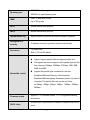
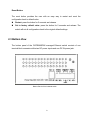
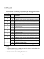
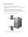
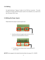
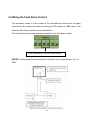
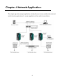
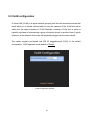
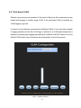
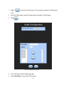
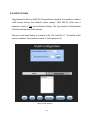
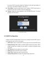
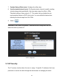
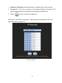
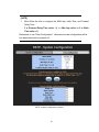
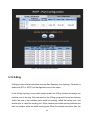
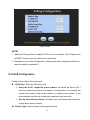
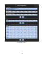
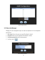
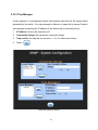
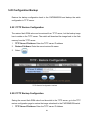
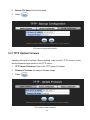
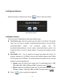
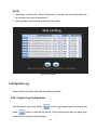
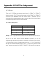
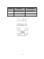
INSTALLATION AND OPERATION MANUAL
CWFE8MS/DIN
INDUSTRIAL GRADE MANAGED
ETHERNET SWITCH WITH (8) 10/100TX PORTS
V2.0 – March 2011
The ComNet CWFE8MS/DIN Managed Ethernet Switch provides transmission of 10/100 BASE-T Ethernet data.
These units are available for use with conventional CAT-5e copper transmission media. Up to 8 electrical ports
are available for easily implementing point-to-point, linear add-drop, drop-and-repeat, star or true self-healing
ring and mesh network system architectures. The electrical ports support the 10/100 Mbps (10/100 BASE-TX)
Ethernet IEEE 802.3 protocol. Auto-negotiating and auto- MDI/MDIX features are provided for simplicity and ease
of installation. Plug-and-play design ensures ease of installation, and no electrical or optical adjustments are ever
required. The CWFE8MS/DIN incorporates LED indicators for monitoring the operating status of the managed
switch and network.
FCC Warning
This Equipment has been tested and found to comply with the limits for a Class-A digital
device, pursuant to Part 15 of the FCC rules. These limits are designed to provide
reasonable protection against harmful interference in a residential installation. This
equipment generates, uses, and can radiate radio frequency energy. It may cause
harmful interference to radio communications if the equipment is not installed and used
in accordance with the instructions. However, there is no guarantee that interference will
not occur in a particular installation. If this equipment does cause harmful interference to
radio or television reception, which can be determined by turning the equipment off and
on, the user is encouraged to try to correct the interference by one or more of the
following measures:
Reorient or relocate the receiving antenna.
Increase the separation between the equipment and receiver.
Connect the equipment into an outlet on a circuit different from that to which the
receiver is connected.
Consult the dealer or an experienced radio/TV technician for help.
CE Mark Warning
This is a Class-A product. In a domestic environment this product may cause radio
interference in which case the user may be required to take adequate measures.
Content
Chapter 1 Introduction..............................................................1
1.1 Hardware Features ............................................................1
1.2 Software Features .............................................................3
1.3 Package Contents .............................................................6
Chapter 2 Hardware Description..............................................7
2.1 Physical Dimensions..........................................................7
2.2 Front Panel ........................................................................7
2.3 Bottom View.......................................................................8
2.4 DIP-switch..........................................................................9
2.5 LED Indicators .................................................................10
Chapter 3 Hardware Installation ............................................11
3.1 Installation Steps .............................................................11
3.2 DIN-Rail Mounting ...........................................................12
3.3 Wall Mount Plate Mounting..............................................14
3.4 Cabling.............................................................................15
3.5 Wiring the Power Inputs...................................................15
3.6 Wiring the Fault Alarm Contact........................................16
Chapter 4 Network Application ..............................................17
4.1 X-Ring Application ...........................................................18
4.2 Coupling Ring Application................................................19
4.3 Dual Homing Application .................................................20
Chapter 5 Web-Based Management ......................................21
5.1 About Web-based Management ......................................21
5.2 Preparing for Web Management......................................22
5.3 System Login ...................................................................22
5.4 System Information..........................................................24
5.5 Port status........................................................................25
5.5.1 Single Port Information ............................................................. 26
5.6 Port Statistics...................................................................27
5.7 Port Control......................................................................27
5.8 Port Mirroring ...................................................................28
5.9 VLAN configuration..........................................................30
5.9.1 Port-based VLAN...................................................................... 31
5.9.2 802.1Q VLAN ........................................................................... 34
5.10 Alert ...............................................................................39
5.10.1 Email Alert Configuration........................................................ 39
5.10.2 Event Configuration ................................................................ 40
5.10.3 Power Alarm Configuration..................................................... 42
5.11 IP Configuration .............................................................42
5.12 SNTP Configuration.......................................................43
5.13 IP Security .....................................................................44
5.14 RSTP Configuration.......................................................46
5.14.1 System Configuration ............................................................. 46
5.14.2 Per Port Configuration ............................................................ 48
5.15 X-Ring............................................................................49
5.16 QoS Configuration .........................................................51
5.17 IGMP..............................................................................54
5.18 Security Manager...........................................................55
5.19 SNMP Configuration ......................................................56
5.19.1 System Options ...................................................................... 56
5.19.2 Community strings.................................................................. 56
5.19.3 Trap Manager ......................................................................... 57
5.20 Configuration Backup ....................................................58
5.20.1 TFTP Restore Configuration................................................... 58
5.20.2 TFTP Backup Configuration ................................................... 58
5.21 TFTP Update Firmware .................................................59
5.22 Factory Default ..............................................................60
5.23 Save Configuration ........................................................60
5.24 System Reboot ..............................................................61
5.25 Rate Control...................................................................61
5.26 System Log....................................................................62
5.26.1 System Log Configuration ...................................................... 62
5.26.2 Event Configuration ................................................................ 64
Trouble Shooting.....................................................................66
Appendix A-RJ45 Pin Assignment ........................................67
Chapter 1 Introduction
The CWFE8MS/DIN managed Ethernet switch is a cost-effective solution and meets the
high reliability requirements demanded by commercial applications. The CWFE8MS/DIN
managed Ethernet switch can be easily managed through the Web GUI. It also provides
the X-Ring function that can prevent network connection failures.
1.1 Hardware Features
IEEE 802.3 10Base-T Ethernet
IEEE 802.3u 100Base-TX Fast Ethernet
IEEE802.3x Flow Control and Back-pressure
Standard
IEEE802.1d spanning tree /
IEEE802.1w rapid spanning tree
IEEE802.1p class of service
IEEE802.1Q VLAN Tag
Protocol
CSMA/CD
Technology
Store and forward switching architecture
Transfer Rate
14,880 bps for Ethernet port
148,800 bps for Fast Ethernet port
Transfer packet size
64bytes to 1522 bytes (with VLAN tag)
MAC address
2K MAC address table
Memory Buffer
1Mbits
1
Back-plane
Packet throughput
ability
1.6 Gbps
2.38Mpps @64bytes (8TX)
Per port: Link/Activity (Green), Full duplex/Collision (Yellow)
Per unit: Power (Green)
Power 1 (Green)
LED
Power 2 (Green)
Fault (Yellow)
Master (Green)
10Base-T: 2-pair UTP/STP Cat. 3, 4, 5 cable
Network Cable
EIA/TIA-568 100-ohm (100m)
100Base-TX: 2-pair UTP/STP Cat. 5 cable
EIA/TIA-568 100-ohm (100m)
12 ~48 VDC
Power Supply
Redundant power with polarity reverse protect function and
connective removable terminal block for master and slave
power
Power consumption
Install
6.72 Watts
DIN rail kit and wall mount ears are provided for wall mount or
DIN-rail cabinet install
Provides one relay output for port breakdown, power failure
Alarm
and provides DIP-switch to mask link down port.
Alarm Relay current carry ability: 1A @ DC24V
Operation Temp.
0 to 70 (32 to 158)
2
Operation Humidity
Storage
5% to 95% (Non-condensing)
-40 to 85
Temperature
Case Dimension
IP-30, 54 mm (W) x 135 mm (H) x 105mm (D)
FCC Class A, CE EN61000-4-2 (ESD), CE EN61000-4-3 (RS),
CE EN-61000-4-4 (EFT),
EMI
CE EN61000-4-5 (Surge), CE EN61000-4-6 (CS), CE
EN61000-4-8, CE EN61000-4-11,
CE EN61000-4-12, CE EN61000-6-2, CE EN61000-6-4
Safety
Stability testing
UL, cUL, CE/EN60950-1
IEC60068-2-32 (Free fall), IEC60068-2-27 (Shock),
IEC60068-2-6 (Vibration)
1.2 Software Features
SNMP management
Management
Web interface management
One default button for system default setting
4 selection rules for different type of packet combination:
All of packet
Packet filter
Broadcast/ multicast/ unknown unicast packet
Broadcast/ multicast packet
Broadcast packet only
3
RFC 1213 MIBII
RFC 1493 Bridge MIB
RMON RFC 1757
RFC 2674 VLAN MIB
SNMP MIB
RFC 1643 Ethernet like MIB
RFC1215 Trap MIB
IGMP MIB.
Private MIB for switch information, X-Ring, port alarm, TFTP
firmware upgrade, reset, port mirror, IP security
Up to 3 Trap stations
Cold start, Port link Up, Port link down, Authentication Failure
SNMP Trap
Private Trap for power status
Port Alarm configuration
Fault alarm, X-Ring
Class of service
Quality of service
IEEE802.1p class of service support
Per port provides 4 priority queues
The quality of service support port based
Tag based and IPv4 Type of service
2 ports for X-Ring to provide redundant backup feature and
X-Ring
the recovery time below 300ms. It also supports coupling ring
function. Ring and coupling port configure by web interface
and ringmaster by hardware DIP switch
Port based VLAN
VLAN
IEEE802.1Q Tag VLAN
Both of port based and Tag based VLAN group up to 64
VLANs
4
Spanning tree
IGMP
IEEE802.1d spanning tree
IEEE802.1w rapid spanning tree
IGMP v1 and Query mode
Up to 256 groups
SNTP
Simple network time protocol
SMTP
Simple mail transfer protocol
System Event Log
Support system log record and remote system log server
Management IP
security
Port mirror
IP address security to prevents unauthorized intruder
TX packet only
Both of TX and RX packet
Support ingress packet filter and egress packet limit.
The egress rate control supports all of packet type and the
limit rates are 128kbps, 256Kbps, 512Kbps, 1MB, 2MB,
4MB, and 8MB.
Bandwidth control
Ingress filter packet type combination rules are
Broadcast/Multicast/Unknown Unicast packet,
Broadcast/Multicast packet, Broadcast packet only and all
of packet. The packet filter rate can be set follow
as:1Mbps2Mbps4Mbps8Mbps16Mbps32Mbps
64Mbps
Firmware update
DHCP client
Support TFTP firmware update, TFTP configuration backup
and restore
Provide DHCP client function to obtain IP address from DHCP
serve
5
1.3 Package Contents
Please refer to the package content list below and verify product contents against the
checklist.
CWFE8MS/DIN managed Ethernet switch
One DIN-Rail (attached on the switch)
One wall mount plate and six screws
User manual CD
Compare the contents of your switch with the standard checklist above. If any item is
damaged or missing, please contact ComNet Customer-Care.
6
Chapter 2 Hardware Description
This section introduces the switch hardware spec, port, cabling information, and wiring
installation.
2.1 Physical Dimensions
The CWFE8MS/DIN managed Ethernet switch dimensions are: (W x H x D) is 54mm x
135mm x 105mm
2.2 Front Panel
The front panel of the CWFE8MS/DIN managed Ethernet switch is shown below.
Front Panel of the industrial switch
7
Reset Button
The reset button provides the user with an easy way to restart and reset the
configuration back to default value.
Restart: press the button for 2 seconds and release.
Set to factory default value: press the button for 5 seconds and release. The
switch will set all configurations back to the original default settings.
2.3 Bottom View
The bottom panel of the CWFE8MS/DIN managed Ethernet switch consists of one
terminal block connector within two DC power inputs and one DC IN power jack.
Bottom Panel of the industrial switch
8
2.4 DIP-switch
The switch provides 9 DIP-switches for configuring the relay alarm operational mode and
the ring master operational mode. The default value of Dipswitch is OFF.
DIP Switch No
1
2
3
4
5
Stat
us
Description
OFF
Disable port 1 Alarm
ON
Enable port 1 Alarm. If the port’s link fails, the fault LED will light up.
OFF
Disable port2 Alarm
ON
Enable port 2 Alarm. If the port’s link fails, the fault LED will light up.
OFF
Disable port3 Alarm
ON
Enable por3 t Alarm. If the port’s link fails, the fault LED will light up.
OFF
Disable port4 Alarm
ON
Enable port4 Alarm. If the port’s link fails, the fault LED will light up.
OFF
Disable port 5 Alarm
ON
Enable port5 Alarm. If the port’s link fails, the fault LED will light up.
OFF
Disable port 6 Alarm
ON
Enable port6 Alarm. If the port’s link fails, the fault LED will light up.
OFF
Disable port 7 Alarm
ON
Enable port 7 Alarm. If the port’s link fails, the fault LED will light up.
OFF
Disable port8 Alarm
ON
Enable port8 Alarm. If the port’s link fails, the fault LED will light up.
OFF
Disable the ring master function.
ON
Enable the switch as the ring master in the X-Ring group.
6
7
8
9
[NOTE]
1.
When port-alarm function is enabled, the fault LED will be on and the Alarm relay
will activate when a port failure occurs.
2.
Restart the switch after the X-Ring DIP switch is set.
9
2.5 LED Indicators
There are 7 diagnostic LEDs located on the front panel of the commercial switch. They
display real-time information about the system and operational status. The following
table provides a description of the status LEDs and their meaning for the switch.
LED
Power
Power 1
Power 2
Fault
R. M. (Ring
Master)
LNK/ACT
(Port 7 & 8)
FDX/COL
(Port 7 & 8)
Status
Meaning
Green
The switch is powered on.
Off
The switch is not powered on.
Green
Power on
Off
No power input
Green
Power on
Off
No power input
Yellow
Power failure, UTP port failure or Fiber port failure
Off
No Power failure, UTP port failure or Fiber port failure occurring
Green
The switch is the master of X-Ring group.
Off
The switch is not the ring master in X-Ring group.
Green
The port is linked.
Blinks
The port is transmitting or receiving packets from the TX device.
Off
No device attached
Yellow
The port is operating in full-duplex mode.
Blinks
Collision of Packets occurs in the port.
Off
The port in half-duplex mode or no device is attached
10
Chapter 3 Hardware Installation
This section describes how to install the CWFE8MS/DIN managed Ethernet switch and
the installation points attached.
3.1 Installation Steps
1. Unpack the commercial switch
2. Check the DIN-Rail mounting bracket is on the switch. If the DIN-Rail is not attached,
please refer to the DIN-Rail Mounting section for DIN-Rail installation. If the user
wants to wall mount the switch, then please refer to Wall-Mount Plate Mounting
section for wall mount plate installation.
3. To hang the Switch on the DIN-Rail track or wall, please refer to the Mounting
Installation section.
4. Power on the Industrial switch. To wire the power; please refer to the Wiring the
Power Inputs section. The power LED on the Switch will light up. Please refer to the
LED Indicators section for the meaning of LED lights.
5. Prepare the twisted-pair, straight-through Category 5 cable for the Ethernet
connection.
6. Insert one side of RJ-45 cable (category 5) into the Switch Ethernet port (RJ-45 port)
and another side of RJ-45 cable (category 5) to the network devices’ Ethernet port
(RJ-45 port), ex: Switch, PC or Server. The UTP port (RJ-45) LED on the Switch will
light up when the cable connected with the network device. Please refer to the LED
Indicators section for LED light meaning.
[NOTE] Be sure the connected network devices supports MDI/MDI-X. If it does not
support then use the crossover category-5 cable.
7. When all connections are complete and LED lights all show normal operation, the
installation is complete.
11
3.2 DIN-Rail Mounting
The DIN-Rail is attached to the switch when it leaves factory. If the DIN-Rail is not
attached to the commercial switch, please see the following illustration to attach the
DIN-Rail on the switch. Follow the steps below to install the industrial switch.
Rear Panel of the switch
Use the screws to screw the DIN-Rail on the industrial switch
12
1.
Insert the top of DIN-Rail into the track.
2.
Lightly push the DIN-Rail into the track.
3.
Check that the DIN-Rail is secured to the track.
4.
To remove the switch from the track, reverse above steps.
13
3.3 Wall Mount Plate Mounting
Follow the steps below to mount the switch with a wall mount plate.
1. Remove the DIN-Rail from the industrial switch; loosen the screws and remove the
DIN-Rail.
2. Place the wall-mount plate on the rear panel of the commercial switch.
3. Use the screws to attach the wall mount plate on the commercial switch.
4. Use the hook holes at the corners of the wall mount plate to attach the switch to the
wall.
5. To remove the wall mount plate, reverse above steps.
Screw the wall mount plate on the Industrial media converter
14
3.4 Cabling
Use eight twisted-pair, Category 5 cables for the RJ-45 port connection.
The cable
between the converter and the link partner (switch, hub, workstation, etc.) must be less
than 100 meters (328 ft.) long.
3.5 Wiring the Power Inputs
Please follow below steps to insert the power wire.
V-
V+
V-
V+
1. Insert the positive and negative wires into the V+ and Vconnector on the terminal block connector.
2. To tighten the wire-clamp screws for preventing the DC
wires to loose.
[NOTE] The wire gauge for the terminal block should be in the range of 12~ 24 AWG.
15
3.6 Wiring the Fault Alarm Contact
The fault-alarm contact is in the middle of the terminal-block connector as the figure
shows below. By inserting the wires and setting the DIP switches to “ON” status, it will
detect the fault status of power and port link failures.
The following figure shows an application example for the fault alarm contact.
1A@24V
Insert the wires into the fault alarm contact
[NOTE] The wire gauge for the terminal block should be in the range between 12~ 24
AWG.
16
Chapter 4 Network Application
This chapter provides sample applications to help the user to have a better idea of actual
switch function applications. A sample application of the switch is seen below:
17
4.1 X-Ring Application
The CWFE8MS/DIN switch supports the X-Ring protocol that can allow your network
system to recover from a network connection failure within 300ms or less, making your
network system more reliable. The X-Ring algorithm is similar to the spanning tree
protocol (STP) algorithm but it has a faster recovery time than STP. An X-Ring
application figure is shown below:
18
4.2 Coupling Ring Application
Within the network there maybe more than one X-Ring group. By using the coupling ring
function more than one X-Ring can be connect for redundant backup. This can ensure
the transmission between the two ring groups will not fail. A sample of the coupling ring
application figure is shown below:
19
4.3 Dual Homing Application
The Dual Homing function is designed to prevent a lost connection between the X-Ring
group and upper level/core switch. The Dual Homing function only works when the
X-Ring function is active. The maximum allowable Dual Homing port is set at one in a
X-Ring group.
[NOTE] In Dual Homing application architecture, the upper level switches need to enable
Rapid Spanning Tree protocol.
20
Chapter 5 Web-Based Management
This section introduces the configuration and functions of the Web-Based management.
The following configuration steps are based on the firmware version 1.06.
5.1 About Web-based Management
On the CPU board of the switch there is an embedded HTML web site residing in the
flash memory, which offers advanced management features and allows users to manage
the switch from anywhere on the network through a standard browser such as Microsoft
Internet Explorer.
The Web-Based Management supports Internet Explorer 5.0. And, it is applied for Java
Applets for reducing network bandwidth consumption, enhance access speed and
present an easy viewing screen.
[NOTE] By default, IE5.0 or later version does not allow Java Applets to open sockets.
The user has to intentionally modify the browser settings to enable Java Applets to use
network ports.
21
5.2 Preparing for Web Management
Before using web management, install the switch on the network and make sure that any
one of PCs on your network can connect to the switch through the web browser. The
switch default settings for the IP Address, subnet mask, username and password are
identified below:
IP Address: 192.168.10.1
Subnet Mask: 255.255.255.0
Default Gateway: 192.168.16.254
User Name: admin
Password: admin
5.3 System Login
1.
Launch the Internet Explorer on the PC.
2.
Key in “http:// “+” the IP address of the switch”, and then Press “Enter”.
3.
The login screen will appear right after.
4.
Key in the user name and password. The default user name and password is
“admin”.
5.
Click “Enter” or ”OK”, and the home screen of the Web-based management
appears right after.
22
Login Screen
23
5.4 System Information
System Description: Display the description of switch. Read only cannot be
modified.
Firmware Version: Display the switch’s firmware version.
Kernel Version: Display the kernel software version.
Hardware version: Display the switch hardware version.
MAC Address: Display the unique hardware address assigned by manufacturer
(default)
Switch settings interface
[NOTE] Remember to use “Save Configuration”, otherwise the new configuration will be
lost when the switch is powered off.
24
5.5 Port status
Display every port’s status depending on user’s setting and the negotiation result.
Port: the port’s number
Type: the speed mode, ex: 100TX = 100Mbps
Link: Down means No Link. UP is for Link
State: Displays port status as disabled or enabled. Unlink will be treated as off
Negotiation: Displays the auto negotiation mode: auto/force. Config means the
value that user has configured. Actual means the current value of the port.
Speed Duplex: Displays port connection speed. Config means the value that user
configured. Actual means the current value of the port.
Flow Control: Displays the flow control status as enabled or disabled with full mode.
Config means the value that the user configured. Actual means the current value of
the port.
Port Status interface
25
5.5.1 Single Port Information
Selecting the port on the panel figure on the left side of web page, the user will see the
single port information window callout as below figure shows.
Port information interface
26
5.6 Port Statistics
Display the current port statistic information. Select
to clean all counts.
Port Statistics Interface
5.7 Port Control
Modifying the port status
1.
Select the port by scrolling the Port column
2.
State: disable or enable control of this port
3.
Negotiation: set auto negotiation mode as Auto, Nway (specify the speed/duplex
on this port and enable auto-negotiation), or Force
4.
Speed: Set the speed of the port
5.
Duplex: Set the port in full-duplex or half-duplex mode
6.
Flow control: Set flow control function as Symmetric or Asymmetric in Full
27
Duplex mode. The default value is Disable
7. Click
button to apply configuration
8. The port’s current configuration is display in column below when the port is selected
[NOTE] Remember to use “Save Configuration”, otherwise the new configuration will be
lost when the switch is powered off.
Port Control interface
5.8 Port Mirroring
The Port mirroring is a method to monitor traffic in switched networks. Traffic through
ports can be monitored by one specific port. That is the traffic that goes in or out of
monitored ports will be duplicated into mirror port.
1.
Port Mirroring Mode: set mirror mode – Disable, TX, and Both. The default is
Disable.
2.
Analysis Port: the mirror port that will receive all monitored port traffic. The mirror
port can connect with the LAN analyzer or Netxray.
28
3.
Monitor Port: the ports that the user wants to monitor. All monitor port traffic will be
copied to the mirror port. A maximum of 7 monitor ports can be selected in one
switch. The user can choose the port to be monitored in one mirror mode.
[NOTE]
1.
If you want to disable the function, select the monitor mode as disabled.
Remember to use “Save Configuration”, otherwise the new configuration will be
lost when the switch is powered off.
Prot Mirroring interface
29
5.9 VLAN configuration
A Virtual LAN (VLAN) is a logical network grouping that limits the broadcast domain that
would allow you to isolate network traffic so only the members of the VLAN will receive
traffic from the same members of VLAN. Basically, creating a VLAN from a switch is
logically equivalent of reconnecting a group of network devices to another Layer 2 switch.
However, all the network devices are still physically plugged into the same switch.
The switch supports port-based and 802.1Q (tagged-based) VLAN. In the default
configuration, VLAN operation mode default is Disable.
VLAN Configuration interface
30
5.9.1 Port-based VLAN
Packets can go among only members of the same VLAN group. All unselected ports are
treated as belonging to another single VLAN. If the port-based VLAN is enabled, the
VLAN-tagging is ignored.
In order for an end station to send packets to different VLANs, it has to be either capable
of tagging packets it sends with VLAN tags or attached to a VLAN-aware bridge that is
capable of classifying and tagging the packet with a different VLAN ID, based on not only
default PVID but also other information about the packet, such as the protocol.
VLAN – PortBase interface
31
1.
Select
to add a new VLAN group. The maximum number of VLAN groups
is 64.
2.
Enter the VLAN name, group ID and group the members of VLAN group
3.
Click
VLAN—PortBase Add interface
4.
The VLAN group list will display right after.
5.
Select Next Page to view other VLAN groups.
32
6.
Use
button to delete unwanted VLAN groups.
7.
Use
button to modify an existing VLAN group.
Remember to use “Save Configuration”, otherwise the new configuration will be lost
when the switch is powered off.
33
5.9.2 802.1Q VLAN
Tagged-based VLAN is an IEEE 802.1Q specification standard. It is possible to create a
VLAN across devices from different switch venders. IEEE 802.1Q VLAN uses a
technique to insert a “Tag” into the Ethernet frames. The Tag contains a VLAN Identifier
(VID) that indicates the VLAN numbers.
All ports on the switch belong to a default VLAN. The VLAN ID is 1. The default VLAN
cannot be deleted. The maximum number of VLAN groups is 64.
802.1q VLAN interface
34
Basic
1.
Select
2.
Management VLAN ID: this is used for Remote Management Security. It includes
button
remote management that includes telnet, SNMP, and Web browse the switch when
the port of the VLAN group ID is equal to the Management VLAN ID. Enter the
specific VLAN ID number in Management VLAN ID column and select the check box,
and select the
button to enable the function. For example: if the
management VLAN ID is 101, the VLAN group ID 101 includes the port 1, 2, and 4.
Therefore, only port 1, 2, and 4 can remotely manage the switch. If the port is in two
different VLAN groups and one of VLAN group ID is equal to the assigned
Management VLAN ID, it still has the right to remotely manage the switch.
3.
Group Name: Assign a name for the new VLAN
4.
VLAN ID: Fill in a VLAN ID (2~ 4094). The default is 1
5.
Select the ports from the ports list, and then, select
VLAN group
35
to group the port as a
802.1q VLAN –Add interface
6.
Select Next, and then the page will display as shown below:
36
7.
Set the outgoing frames that are VLAN-Tagged frames or untagged, and then select
Tag: outgoing frames with VLAN-Tagged
Untag: outgoing frames without VLAN-Tagged
Port VID: Configure port VID settings
1.
Port VLAN ID: Enter the port VLAN ID
2.
Select
3.
To reset to default value, click Default button
37
802.1q VLAN – Port VLAN ID interface
Remember to use “Save Configuration”, otherwise the new configuration will be lost
when the switch is powered off.
38
5.10 Alert
There are three kinds of alerts – e-mail, event, and power alarm. You can configure each
alert function, as required.
5.10.1 Email Alert Configuration
When the specific events occur, the system will send the alert to the email account that is
assigned by user. The user can set up the mail server IP, mail account, and forwarded
email account for receiving the event alert.
1.
Email Alert: enable or disable the email alert function
2.
SMTP Server IP Address: Set up the mail server IP address
3.
Authentication: Mark the check box to enable and configure the email account and
password for authentication
Mail Account: Set up the email account to receive the alert. Ex:
[email protected]. The email account must exist on the mail server, which
user had set up in SMTP Server IP Address column
4.
Password: The email account password
Confirm Password: reconfirm the password
E-mail Address of Recipient 1 ~ 4: Assign up to 4 e-mail accounts for receiving
the alert
5.
Select
39
Email Alert Configuration interface
5.10.2 Event Configuration
The selected events that occur will send out the alert to the assigned SMTP server and
also can set up port events for alerting.
System event selection: 4 selections – device cold start, Power status, SNMP
Authentication Failure, and X-Ring topology changes. Select the checkbox to select
the event. When a selected event occurs, the system will send out the alert.
Device cold start: when the device executes a cold start action, the system will
send out the alert to the dedicate SMTP server.
Power status: when the device power status has changed, the system will
send out the alert to the dedicated SMTP server.
SMNP Authentication Failure: when the SNMP authentication fails, the
system will send out the alert to the dedicate SMTP server.
X-Ring topology change: when the X-Ring topology has changed, the system
will send out the alert to dedicate SMTP server
40
Port event selection: Select the per port events. Per port has 3 selections – Link
UP, Link Down, and Link UP & Link Down. Disable means no event is selected.
Link UP: the system will send out an alert when a port connection is up only.
Link Down: the system will send out an alert message when the port
connection is down only.
Link UP & Link Down: the system will send out an alert message when the
port connection is up and down.
Select
after selecting
Event Configuration interface
41
5.10.3 Power Alarm Configuration
Power alarm function enables the Relay alarm action. Without enabling the power alarm
function, the Relay alarm action will not work even if the Relay alarm is set. Mark the
check box and select
button.
Power Alarm interface
5.11 IP Configuration
Configure the IP Settings and DHCP client function, and then select
to apply
the new IP settings.
DHCP Client: Enable or Disable the DHCP client function. When DHCP client
function is enabled, the switch will be assigned an IP address from the network
DHCP server. The DHCP server assigned IP address will replace the default IP
address. After selecting the Apply button, a popup dialog box will appear and inform
the user that when the DHCP client is enabled, the current IP address will be lost
and user can find the new IP address on the DHCP server. To cancel the DHCP
client function, select “cancel”.
IP Address: Assign the IP address that your network is using. If DHCP client
function is enabled and then the user does not need to assign the IP address. And,
42
the network DHCP server will assign the IP address for the switch and display it in
this column. The default IP Address is 192.168.16.1.
Subnet Mask: Assign the subnet mask of the IP address. If DHCP client function is
enabled the user does not need to assign the subnet mask.
Gateway: Assign the network gateway for the CWFE8MS-DIN switch. The default
gateway is 192.168.16.254.
IP configuration interface
5.12 SNTP Configuration
Configure the SNTP (Simple Network Time Protocol) settings that allow SNTP users to
synchronize the switch’s clock to the Internet.
1.
SNTP Client: enable or disable SNTP function to get the time from the SNTP server
2.
Daylight Savings Time: enable or disable daylight savings time function. When
daylight savings time is enabled, the user needs to configure the daylight savings
time period
3.
UTC Timezone: Set the switch’s time zone location.
4.
SNTP Sever IP: Set the SNTP server IP address
5.
Switch Timer: Display the switch’s current set time
6.
Daylight Saving Period: Configure the daylight savings time period
43
7.
Daylight Saving Offset (mins): Configure the offset value
8.
Synchronization Interval (secs): The Synchronization Interval is used for sending
synchronizing packets periodically. User can assign range from 64s to 1024s.
The default setting of these values is “0”. This means that you disable the auto
synchronization feature in SNTP client mode. You can enable this feature when
selecting the interval range from 64s~1024s.
9.
Select
Remember to use “Save Configuration”, otherwise the new configuration will be lost
when the switch is powered off.
SNTP Configuration
5.13 IP Security
The IP security function allows the user to assign 10 specific IP addresses that have
permission to access the switch through the web browser for managing the switch.
44
1.
Enable the IP Security: mark the check box to enable the IP security function.
2.
Security IP 1 ~ 10: user can assign up to 10 specific IP address. Only these 10 IP
address can access and manage the switch through the Web browser.
3.
Select
button to apply the configuration
Remember to use “Save Configuration”, otherwise the new configuration will be lost
when the switch is powered off.
IP Security Interface
45
5.14 RSTP Configuration
The Rapid Spanning Tree Protocol (RSTP) is an evolution of the Spanning Tree Protocol
and provides for faster spanning tree convergence after a topology change. The system
also supports STP and the system will auto-detect the connected device that is running
STP or RSTP protocol.
5.14.1 System Configuration
1.
The Root Bridge information of Spanning Tree is for viewing.
2.
Modify RSTP state. After modifying, select
RSTP mode: enables RSTP function before configuring the related parameters
Priority (0-61440): a value used to identify the root bridge. The bridge with the
lowest value has the highest priority and is selected as the root. If the values
change, user has to reboot the switch. The value must be a multiple of 4096
according to the protocol standard rule.
Max Age (6-40): the number of seconds a bridge waits without receiving
Spanning-tree
Protocol
configuration
messages
before
attempting
a
reconfiguration. Enter a value between 6 through 40.
Hello Time (1-10): the time that controls the switch and sends out the BPDU
packet to check RSTP current status. Enter a value between 1 through 10.
Forward Delay Time (4-30): the number of seconds that a port waits before
changing from its Rapid Spanning-Tree Protocol learning and listening states to
the forwarding state. Enter a value between 4 through 30.
46
[NOTE]
1.
Must follow the rule to configure the MAX Age, Hello Time, and Forward
Delay Time.
2 x (Forward Delay Time value –1) > = Max Age value >= 2 x (Hello
Time value +1)
Remember to use “Save Configuration”, otherwise the new configuration will be
lost when the switch is powered off.
RSTP– System Configuration Interface
47
5.14.2 Per Port Configuration
Configuring the path cost and priority of every port
1. Select the port in Port column
2. Path Cost: The cost of the path to the other bridge from this transmitting bridge at the
specified port. Enter a number 1 through 200000000.
3. Priority: Decide which port should be blocked by priority in the LAN. Enter a number
0 through 240. The value of priority must be the multiple of 16.
4. Admin P2P: Some of the rapid state transactions that are possible within RSTP are
dependent upon whether the port concerned can only be connected to exactly one
other bridge (i.e. it is served by a point-to-point LAN segment), or can be connected
to two or more bridges (i.e. it is served by a shared-medium LAN segment). This
function allows the P2P status of the link to be manipulated administratively. True is
P2P enabled. False is P2P disabled.
5. Admin Edge: The port directly connected to end stations cannot create a bridging
loop in the network. To configure the port as an edge port, set the port to “True”
status.
6. Admin Non STP: The port includes the STP mathematic calculation. True does not
include STP mathematic calculation. False does include the STP mathematic
calculation.
7. Select
button
[NOTE] Remember to use “Save Configuration”, otherwise the new configuration will be
lost when the switch is powered off.
48
RSTP – Per Port Configuration interface
5.15 X-Ring
X-Ring provides a faster redundant recovery than Spanning Tree topology. The action is
similar with STP or RSTP, but the algorithms are not the same.
In the X-Ring topology, every switch should enable the X-Ring function and assign two
member ports in the ring. Only one switch in the X-Ring group would be set as a backup
switch that one of two member ports would be blocking, called the backup port, and
another port is called the working port. Other switches are called working switches and
their two member ports are called working ports. When the network connection fails, the
49
backup port will automatically become a working port to recover from the failure.
The switch supports one Dipswitch for configuring the switch as the ring master or slave
mode. The ring master has the rights to negotiate and place the command to other
switches in the X-Ring group.
If there are 2 or more switches are in master mode, then
software will select the switch with lowest MAC address number as the ring master. The
X-Ring master ring mode will be enabled by the DIP Switch. When the switch is set to the
master ring mode, the X-Ring configuration interface will display the switch as the master
ring with a message. Also, you can identify the switch as the ring master from the R.M.
LED panel on the LED panel on the switch.
The system also supports the coupling ring that can connect 2 or more X-Ring groups for
the redundant backup function and dual homing function that prevents a connection loss
between the X-Ring group and the upper level/core switch.
Enable X-Ring: To enable the X-Ring function. Select the check box to enable the
X-Ring function.
1st & 2nd Working Ports: Assign two ports as the member ports. One port will be
working port and one port will be the backup port. The system will automatically
decide which port is the working port and which port is the backup port.
Enable Coupling Ring: To enable the coupling ring function. Select the check box
to enable the coupling ring function.
Coupling port: assign the member port
Control port: set the switch as the master switch in the coupling ring.
Enable Dual Homing: set up one of the ports on the switch to be the Dual Homing
port. In an X-Ring group, the maximum Dual Homing port is one in each X-Ring
group. Dual Homing only works when the X-Ring function enabled.
Select
to apply the configuration
50
X-Ring Interface
[NOTE]
1. When the X-Ring function is enabled, RSTP has to be disabled. The X-Ring function
and RSTP function cannot be active at the same time.
2. Remember to use “Save Configuration”, otherwise the new configuration will be lost
when the switch is powered off.
5.16 QoS Configuration
Configure Qos setting of the every port.
QoS Policy: Select the QoS policy rule
Using the 8,4,2,1 weight fair queue scheme: the switch will follow 8:4:2:1
rate to process priority queue from highest to lowest queue. For example: the
system will process 8 high queue packets, 4 middle queue packets, 2 low
queue packets, and the one lowest queue packets at the same time.
Use the strict priority scheme: the higher queue will always be process first,
except higher queue is empty.
Priority Type: each port has 5 priority type selections
51
Port-base: the port priority will follow the default port priority that the user has
assigned – High, middle, low, or lowest
COS only: the port priority will only follow the COS priority that the user has
assigned
TOS only: the port priority will only follow the TOS priority that the user has
assigned
COS first: the port priority will follow the COS priority first, and then other
priority rule
TOS first: the port priority will follow the TOS priority first, and the other priority
rule
COS priority: Set the COS priority level 0~7
TOS priority: the system provides 0~63 TOS priority level. Each level has 4 types of
priority – high, mid, low, and lowest. The default value is “lowest” priority for each
level. When the IP packet is received, the system will check the TOS level value in
the IP packet that has been received. For example: user set the TOS level 25 is high.
The port 1 is following the TOS priority policy. When the packet received by port 1,
the system will check the TOS value of the received IP packet. If the TOS value of
received IP packet is 25(priority = high), and then the packet priority will have highest
priority.
[NOTE] QoS and rate control cannot exist at the same time.
52
QoS configuration Interface
53
5.17 IGMP
The Internet Group Management Protocol (IGMP) is an internal protocol of the Internet
Protocol (IP) suite. IP manages multicast traffic by using switches, routers, and hosts
that support IGMP. Enabling IGMP allows the ports to detect IGMP queries and report
packets and manage IP multicast traffic through the switch. IGMP has three fundamental
types of message as follows:
Message
Description
A message sent from the querier (IGMP router or
Query
switch) asking for a response from each host
belonging to the multicast group.
A message sent by a host to the querier to indicate
Report
that the host wants to be or is a member of a given
group indicated in the report message.
A message sent by a host to the querier to indicate
Leave Group
that the host has quit to be a member of a specific
multicast group.
The User can enable IGMP protocol and IGMP Query function here. The IGMP
snooping information that identifies VLAN ID, member port, and IP multicast address
range from 224.0.0.0 through 239.255.255.255 will be displayed as below:
[NOTE] Remember to use “Save Configuration”, otherwise the new configuration will be
lost when the switch is powered off.
54
IGMP Snooping interface
5.18 Security Manager
Changing the web management login user name and password for the management
security issue
1.
User name: Enter in the new user name (The default is “admin”)
2.
Password: Enter in the new password (The default is “admin”)
3.
Confirm password: Re-enter the new password
4.
And then, select
Security Manager interface
55
5.19 SNMP Configuration
The SNMP is a Protocol that governs the transfer of information between management
and agent. The switch supports SNMP V1.
Define management stations as trap managers and to enter SNMP community strings.
Also, define a name, location, and contact person for the switch. Fill in the system
options data, and then click
to update the changes.
5.19.1 System Options
1.
Name: Enter a name for the switch
2.
Location: Enter the switch physical location
3.
Contact: Enter the name of contact person or organization
5.19.2 Community strings
Community strings serve as password for MIB read or write.
1.
Strings: Fill the name of string
2.
RO: Read only. Enables requests accompanied by this string to display MIB-object
information
3.
RW: Read write. Enables requests accompanied by this string to display MIB-object
information and to set MIB objects
4.
Select
56
5.19.3 Trap Manager
A trap manager is a management station that receives traps that are the system alerts
generated by the switch. If no trap manager is defined, no traps will be issued Create a
trap manager by entering the IP address of the station and a community string.
1.
IP Address: Enter in the trap device IP
2.
Community Strings: the trap device community strings
3.
Trap version: the trap has two versions – v1 or v2, select one of them
4.
Select
SNMP Management interface
57
5.20 Configuration Backup
Restore the backup configuration back to the CWFE8MS/DIN and backup the switch
configuration to TFTP server.
5.20.1 TFTP Restore Configuration
The restore flash ROM value can be restored from TFTP server, but the backup image
has to reside on the TFTP server. The switch will download the image back to the flash
memory from the TFTP server.
1.
TFTP Server IP Address: Enter the TFTP server IP address
2.
Restore File Name: Enter the correct restore file name
3.
Select
TFTP Restore Configuration interface
5.20.2 TFTP Backup Configuration
Saving the current flash ROM value from the switch to the TFTP server, go to the TFTP
restore configuration page to restore the image value back to the CWFE8MS/DIN switch.
1.
TFTP Server IP Address: Enter the TFTP server IP Address
58
2.
Backup File Name: Enter the file name
3.
Select
TFTP Backup Configuration interface
5.21 TFTP Update Firmware
Updating the switch’s firmware. Before updating, make sure the TFTP server is ready
and the firmware image resides on the TFTP server.
1.
TFTP Server IP Address: Enter in the TFTP server IP address
2.
Firmware File Name: the name of firmware image
3.
Select
TFTP Update Firmware interface
59
5.22 Factory Default
Resetting the switch to the default configuration. The IP address, subnet mask, default
gateway, username, and password will remain as the user had configured it. Select
Default button to reset the switch to the default setting.
Factory Default interface
5.23 Save Configuration
Saving the switch configuration to the flash memory. If you power off the switch without
saving, all configuration changes will lost. Select the
configuration.
Save Configuration Interface
60
button to the save the
5.24 System Reboot
Reboot the switch in software reset. Select
button to reboot the switch.
System Reboot interface
5.25 Rate Control
Set up every port’s bandwidth rate and packet limitation type.
Limit Packet type: select the packet type that needs to be filtered. The packet
types have all types of packets, broadcast/multicast/unknown uni-cast packet,
broadcast/multicast
packet,
and
broadcast
packet
only.
The
broadcast/multicast/unknown uni-cast packet, broadcast/multicast packet, and
broadcast packet are only for ingress packets. The egress rate supports all type
packets.
Band Width: Port1 ~ Port 8, supports port ingress and egress rate control. For
example, assume port 1 is 10Mbps. Users can set its effective egress rate at 1Mbps,
with its ingress rate is 500Kbps. The switch performs the ingress rate by counting
packets to meet the specified rate.
Ingress: select the effective port ingress rate. The valid range value is 1MB,
2MB, 4MB, 8MB, 16MB, 32MB and 64MB. The default value is Disable.
Egress: select the port effective ingress rate. The valid range value is 128kbps,
256Kbps, 512Kbps, 1MB, 2MB, 4MB, and 8MB. The default value is Disable.
Select
button to apply the configuration.
61
[NOTE]
1. Remember to execute the “Save Configuration”, otherwise the new configuration will
be lost when the switch is powered off.
2. QoS and Rate control cannot be existed at the same.
Rate Control Interface
5.26 System Log
Set up system log events and view the system log events.
5.26.1 System Log Configuration
View the system log events. Select
select
button to get newest system log events and
button to clear the log events. If log event list more than one page, drag
down the list to switch to different page.
62
System Log Client Mode: Select in Client Only, Server Only, or Both mode
System Log Server IP: Assign the system log server IP address
Select
button to apply the configuration
System Log Configuration interface
63
5.26.2 Event Configuration
Select the system log events. When selected events occur, the system will send out the
log information. Also, per port log events can be selected.
System event selection: 4 selections – device cold start, power status, SNMP
Authentication Failure, and X-Ring topology change. Mark the checkbox to select
the event. When selected events occur, the system will produce the logs.
Device cold start: when the device executes cold start action, the system will
produce a log message.
Power status: when the device power status has changed, the system will
produce a log message.
SNMP Authentication Failure: when the SNMP authentication fails, the
system will produce a log message.
X-Ring topology change: when the X-Ring topology has changed, the system
will produce a log message.
Port event selection: select the per port events. Per port has 3 selections – Link
UP, Link Down, and Link UP & Link Down. Disable means no event is selected.
Link UP: the system will produce a log message when port connection is up
only
Link Down: the system will produce a log message when port connection is
down only
Link UP & Link Down: the system will produce a log message when port
connection is up and down
Select
after selecting
64
Event Configuration interface
65
Trouble Shooting
Verify that is using the right power cord/adapter (DC 12-48V), do not use a power
adapter with DC voltage output greater than 48V, or it will destroy the switch.
Select the proper use unshielded twisted-pair UTP cable to construct your network.
Please check that you are using the correct cable. Use unshielded twisted-pair (UTP)
or shield twisted-pair (STP ) cable for RJ-45 connections: 100 Category 3, 4 or 5
cable for 10Mbps connections or 100 Category 5 cable for 100Mbps connections.
Also be sure that the length of any twisted-pair connection does not exceed 100
meters (328 feet).
Diagnosing LED Indicators: the CWFE8MS-DIN can be easily monitored through
panel indicators to assist in identifying problems, that describes common problems a
user might encounter and where a user can find possible solutions.
If the power indicator does turn on when the power cord is plugged in, there might
be a problem with the power cord. Check for loose power connections, power losses
or surges at the power outlet. If you still cannot resolve the problem, contact the
ComNet for assistance.
If the CWFE8MS-DIN LED indicators are normal and the connected cables are
correct but the packets still cannot be transmitted, please check the system’s
Ethernet devices’ configuration or operational status.
66
Appendix A-RJ45 Pin Assignment
RJ-45 ports
There are 8x 10/100Mbps auto-sensing electrical ports for 10Base-T or 100Base-TX
devices connection. The UTP ports will auto-sense for either 10Base-T or 100Base-TX
connections. Auto MDI/MDIX means that another switch or workstation may be
connected without changing straight through or crossover cabling. See the below figures
for straight through and the crossover cable schematic.
RJ-45 Pin Assignments
Pin Number
Assignment
1
Tx+
2
Tx-
3
Rx+
6
Rx-
[NOTE] “+” and “-” signs represent the polarity of the wires that make up each wire pair.
All ports on this switch support automatic MDI/MDI-X operation, you can use
straight-through cables (See Figure below) for all network connections to PCs or servers,
or to other switches or hubs. In straight-through cable, pins 1, 2, 3, and 6, at one end of
the cable, are connected straight through to pins 1, 2, 3 and 6 at the other end of the
cable. The table below shows the 10BASE-T/100BASE-TX MDI and MDI-X port pin outs.
67
Pin MDI-X
Signal Name
MDI Signal Name
1
Receive Data plus (RD+)
Transmit Data plus (TD+)
2
Receive Data minus (RD-)
Transmit Data minus (TD-)
3
Transmit Data plus (TD+)
Receive Data plus (RD+)
6
Transmit Data minus (TD-)
Receive Data minus (RD-)
Straight Through Cable Schematic
Cross Over Cable Schematic
68
Technical Support
The ComNet Technical Support and Design Center provides technical pre-sale and post-sale
support for Ethernet transmission network and fiber optic system design and assistance for when
you require one-on-one help from an expert. Our Technical Support department is staffed by
some of the most highly experienced, regarded and recognized experts in the industry.
This service is available Monday through Friday, 8:30 a.m. to 5:00 p.m. Eastern Standard Time.
Our direct Design Center phone number is 1-888-678-9427 or you can call 1-203-796-5300 in the
US or +44 (0)113 307 6409 throughout Europe and ask for the technical support, or contact us by
email at [email protected].
World Headquarters
ComNet Europe Ltd
3 Corporate Drive
8 Turnberry Park Road
Danbury, CT 06810 USA
Gildersome, Morley
T 203 796-5300
Leeds, LS27 7LE, UK
F 203 796-5303
T +44 (0)113 307 6400
888 678-9427 Tech Support
F +44 (0)113 253 7462
[email protected]
[email protected]
www.comnet.net
© 2011 Communication Networks. All rights reserved.
The COMNET logo is a registered trademark of Communication Networks Corporation.
Additional Company and product names may be trademarks or registered trademarks of the individual
companies and are respectfully acknowledged and do not imply endorsement.
69