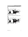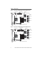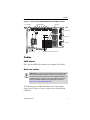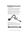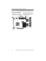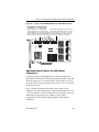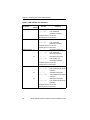
1
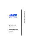
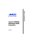
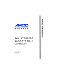
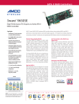
PN 720-0158-00 March 2007 Installation Guide 3ware® 9650SE Serial ATA RAID Controller Copyright ©2004-2007 Applied Micro Circuits Corporation (AMCC). All rights reserved. This publication may be copied or reproduced for reference purposes only. All other purposes require the express written consent of AMCC, 215 Moffett Park Drive, Sunnyvale, CA 94089. AMCC shall not be responsible or liable for, and shall be held harmless against, any and all damages, claims, and/or disputes that arise from the copying or reproduction of this publication. Trademarks 3ware®, Escalade®, 3DM®, and TwinStor® are all registered trademarks of AMCC. The 3ware logo, 3BM, Multi-Lane, StorSave, StorSwitch, StreamFusion, and R5 Fusion are all trademarks of AMCC. PowerPC and the PowerPC logo are trademarks of International Business Machines Corporation. Linux® is a registered trademark of Linus Torvalds in the United States, other countries, or both. Windows® is a registered trademark of Microsoft Corporation in the United States and other countries. Firefox® is a registered trademark of the Mozilla Foundation. PCI Express® is a registered trademark of PCI-SIG®. All other trademarks herein are property of their respective owners. Disclaimer While every attempt is made to make this document as accurate as possible, AMCC assumes no responsibility for errors or omissions in this document, nor does AMCC make any commitment to update the information contained herein. Table of Contents About this Guide . . . . . . . . . . . . . . . . . . . . . . . . . . . . . . . . . . . . .iv Chapter 1. Getting Started . . . . . . . . . . . . . . . . . . . . . . . . . . . . . 1 Contents of this Package . . . . . . . . . . . . . . . . . . . . . . . . . . . . . . . . . . . . . . 1 System Requirements . . . . . . . . . . . . . . . . . . . . . . . . . . . . . . . . . . . . . . . . 2 9650SE RAID Controller Card Models. . . . . . . . . . . . . . . . . . . . . . . . . . . . 4 Cables . . . . . . . . . . . . . . . . . . . . . . . . . . . . . . . . . . . . . . . . . . . . . . . . . . . . 7 Safety Information . . . . . . . . . . . . . . . . . . . . . . . . . . . . . . . . . . . . . . . . . . 10 Chapter 2. Installing Your 3ware RAID Controller . . . . . . . . . 15 Tools You Need . . . . . . . . . . . . . . . . . . . . . . . . . . . . . . . . . . . . . . . . . . . . Before You Start. . . . . . . . . . . . . . . . . . . . . . . . . . . . . . . . . . . . . . . . . . . . Step 1 (9650SE-2LP). Connect the Cables to the Controller. . . . . . . . . . Step 1 (Multi-lane Controllers). Connect the Cables to the Controller . . . Step 2. Install the Controller in the Computer . . . . . . . . . . . . . . . . . . . . . Step 3. Connect the Cables to the Drives . . . . . . . . . . . . . . . . . . . . . . . . Step 3. Connect Cables to the SATA/SAS Drive Multi-Lane Backplane . Step 4. Connecting Drive Activity LED Indicators (Optional) . . . . . . . . . . Step 5. Finishing Up the RAID Controller Installation . . . . . . . . . . . . . . . Step 6. Configure Your RAID Arrays . . . . . . . . . . . . . . . . . . . . . . . . . . . . 15 15 16 17 18 20 21 21 28 28 Chapter 3. Installing the Battery Backup Unit . . . . . . . . . . . . 29 Tools and equipment required . . . . . . . . . . . . . . . . . . . . . . . . . . . . . . . . . Installation Overview . . . . . . . . . . . . . . . . . . . . . . . . . . . . . . . . . . . . . . . . Installation Instructions . . . . . . . . . . . . . . . . . . . . . . . . . . . . . . . . . . . . . . Replacing the Battery . . . . . . . . . . . . . . . . . . . . . . . . . . . . . . . . . . . . . . . 30 30 32 37 Appendix: Technical Support . . . . . . . . . . . . . . . . . . . . . . . . . 40 Sales and ordering information . . . . . . . . . . . . . . . . . . . . . . . . . . . . . . . . 40 Feedback on this manual. . . . . . . . . . . . . . . . . . . . . . . . . . . . . . . . . . . . . 40 www.3ware.com iii About this Guide Congratulations on your purchase of the 3ware® 9650SE Serial ATA RAID Controller. This guide tells you how to install it. Chapter Description 1 Getting Started Overview of the 3ware RAID controller and important safety factors to keep in mind during installation 2 Installing Your 3ware RAID Controller How to install your 3ware RAID controller 3 Installing the Battery Backup Unit How to install a 3ware Battery Backup Unit (BBU) on your 3ware RAID controller The following additional documentation is available for your 3ware RAID controller on the CD that came with your controller. It is also available through the 3ware website: 3ware Serial ATA RAID Controller User Guide 3ware Serial ATA RAID Controller CLI Guide 3ware HTML Bookshelf is an HTML version of the documentation, combining the User Guide and the CLI Guide. Online help is also available when you are using 3DM 2 (3ware Disk Manager). Additional support information is available in the 3ware Knowledgebase, at this website: http://www.3ware.com/KB iv 3ware 9650SE Serial ATA RAID Controller Installation Guide Chapter 1. Getting Started The 3ware® 9650SE RAID controller provides these features: RAID 6 with simultaneous parity generation to maximize performance 8th-generation StorSwitch™ non-blocking switch fabric for maximum controller output StreamFusion™ optimization of RAID 5 and RAID 6 disk accesses to maximize application performance under heavy loads StorSave Battery Backup Unit (BBU) with write journaling to optimize data protection and performance (BBU must be purchased separately, and is not supported on 9650SE-2LP.) RAID levels 0, 1, 5, 6, 10, 50, Single Disk, JBOD, and Hot Spare (RAID 6 and RAID 50 are available only with 3ware RAID controller models that have 8 or more ports) PCI Express® x1, x4, or x8 connectivity Contents of this Package If you purchased a full retail kit, the following items are included: This document, 3ware 9650SE Serial ATA RAID Controller Installation Guide 3ware CD-ROM with driver, software, and additional documentation Appropriate cables for the 3ware 9650SE model For the 2-port model, two SATA interface cables, one for each port are provided. www.3ware.com 1 Chapter 1. Getting Started For the 4-port, 8-port, 12-port, and 16-port models, Multi-lane™ break-out cables (SFF-8087) are provided, for use with individual drives. Each of these Multi-lane cables supports up to four serial ATA drives. One is provided with the 4-port controller Two are provided with the 8-port controller Three are provided with the 12-port controller Four are provided with the 16-port controller Note: For the 4-port, 8-port, 12-port, and 16-port models. SFF-8087 to SFF-8087 Multi-lane cables, for use with a Multi-lane backplane, can be purchased separately. For details about these cables, see “Multi-lane Cables” on page 7. For the 24-port model, three Multi-Lane M8 cables are provided that each support up to eight serial ATA drives, through connection to Multi-lane (SFF-8087) backplanes. Note: Cables for use with a non Multi-lane backplane (“direct attach”) or with individual drives can be purchased separately. For more about these cables see “Multi-lane M8 fanout cable” on page 9. If you purchased the 3ware RAID controller in a single pack or as part of a bulk pack, cables are not included. System Requirements Motherboard and Slot Requirements A workstation-class or server-class motherboard with PCI-Express® slot that supports the specific 9650SE model, as shown in Table 1. A list of systems that have been tested is available at http://www.3ware.com/products/ compatibility_sata2.asp 2 3ware 9650SE Serial ATA RAID Controller Installation Guide System Requirements Table 1: Required Slots for 3ware RAID Controller Models Controller Model PCI-E X1 PCI-E X4 PCI-E X8 PCI-E x16 9650SE-2LP Yes Yes Yes Yes 9650SE-4LPML No Yes Yes Yes 9650SE-8LPML No Yes Yes Yes 9650SE-12LPML No No Yes Yes 9650SE-16LPML No No Yes Yes 9650SE-24M8 No No Yes Yes Drive Requirements Depending on the particular model, the 3ware RAID controller may be connected to up to twenty-four SATA drives using the supplied interface cables. Drives must meet SATA-1 (1.5 Gb/s) or SATA-2 (3.0 Gb/s) standards. Drives may be of any capacity or physical form factor. A list of tested drives is available at http://www.3ware.com/products/compatability_9650se.asp Note: Shielded and unshielded interface cables for Serial ATA controllers may not exceed 1M (39”) in length. Operating System Requirements Windows 2000, Windows XP, Windows Server 2003, both 32-bit and 64-bit x86 Red Hat Linux, 32-bit and 64-bit x86 SuSE Linux, 32-bit and 64-bit x86 Fedora Core, 32-bit and 64-bit x86 Other versions of Linux, 32-bit and 64-bit x86, using the open source Linux 2.4 or 2.6 kernel driver FreeBSD, 32-bit and 64-bit x86 For the latest driver versions for all operating systems, see the current Release Notes, at http://www.3ware.com/support. www.3ware.com 3 Chapter 1. Getting Started Other Requirements Adequate air flow and cooling Adequate power supply for drives 3DM 2 (3ware Disk Manager), a browser-based application used to configure and maintain RAID units, requires one of the following browsers: Internet Explorer 5.5 and later Mozilla Firefox 1.2 and later Netscape 7 and later Konquerer 3.5.1 In addition: JavaScript must be enabled Cookies must be enabled For best viewing, screen resolution should be 1024 x 768 or greater, with 16-bit color or greater. 9650SE RAID Controller Card Models Figure 1. 2-Port 3ware 9650SE-2LP Serial ATA RAID Controller LED Connector Heat Sink Ports: 0 (on top) 1 (on the bottom) 4 3ware 9650SE Serial ATA RAID Controller Installation Guide 9650SE RAID Controller Card Models Figure 2. 4-Port 3ware 9650SE-4LPML Serial ATA RAID Controller I2C connector LED Connector Heat Sink Ports: 0 thru 3 Slots for battery holder BBU connector and hole for post Figure 3. 8-Port 3ware 9650SE-8LPML Serial ATA RAID Controller I2C connector LED Connectors Heat Sink Ports: 4 thru 7 0 thru 3 Slots for battery www.3ware.com BBU connector and hole for post 5 Chapter 1. Getting Started Figure 4. 12-Port 3ware 9650SE-12ML Serial ATA RAID Controller I2C connector LED Connectors Heat sink Ports: 8 thru 11 4 thru 7 0 thru 3 Holes for battery holder BBU connector and hole for post Figure 5. 16-Port 3ware 9650SE-16ML Serial ATA RAID Controller I2C connector LED Connectors Heat sink Ports: 12 thru 15 8 thru 11 4 thru 7 0 thru 3 Holes for battery holder 6 BBU connector and hole for post 3ware 9650SE Serial ATA RAID Controller Installation Guide Cables Figure 6. 24-Port 3ware 9650SE-24M8 Serial ATA RAID Controller I2C connector LED Connectors Heat sink Ports: 16 thru 23 8 thru 15 0 thru 7 Holes for battery holder BBU connector and hole for post Cables SATA Cables The 2-port 9650SE RAID controller uses standard SATA cables. Multi-lane Cables Important: You should only use AMCC/3ware certified cables with your 3ware RAID controller. Using an incorrect cable can result in drives that are not detected. The appropriate cables are included with your controller. If you must replace a cable, see the list of available cables and associated part numbers at http://3ware.com/products/cables.asp. The following types of Multi-lane cables can be used with the 4-port, 8-port, 12-port, 16-port, or 24-port 3ware 9650SE RAID controllers. www.3ware.com 7 Chapter 1. Getting Started Multi-lane breakout cables for 4-port, 8-port, 12-port, and 16-port ML controllers For use with a backplane that has individual SATA connectors or individual serial ATA drives, Multi-lane breakout cables have an SFF-8087 Multi-lane connector on one end and four individual SATA connectors on the other end (Figure 7). Note: This is the type of cable that ships with most 3ware 9650SE Multi-lane controllers (except the 24-port). Depending on the enclosure you are using, you may need to purchase a different cable to connect the 9650SE controller and the enclosure backplane Figure 7. Multi-lane Serial ATA Breakout Cable (SFF-8087) SFF-8087-to-SFF-8087 Multi-lane cables For use with a multi-lane-enabled drive backplane that has the SFF-8087 mini SATA/SAS 4i connectors, these SFF-8087-toSFF-8087 4i cables have multi-lane connectors on each end (Figure 8). Figure 8. Multi-lane Cable Serial ATA (SFF-8087) 8 3ware 9650SE Serial ATA RAID Controller Installation Guide Cables Multi-lane M8 Y cable Use this cable when connecting a 9650SE-24M8 controller to multi-lane-enabled drive backplanes that have SFF-8087 mini SAS 4i connectors (Figure 9). Figure 9. Multi-lane M8 Cable (SFF-8087) Multi-lane M8 fanout cable When connecting a 9650SE-24M8 controller to individual SATA drives or a backplane that has individual SATA connectors, use the Multi-lane M8 fanout cable. These cables have an M8 connector on one end and eight individual SATA connectors on the other end. They look similar to the Multi-lane serial breakout cable shown in Figure 7, except that they have eight individual connectors instead of four. www.3ware.com 9 Chapter 1. Getting Started Multi-lane converter cables for 4-port, 8-port, 12-port, and 16-port controllers To connect from a 3ware 9650SE multi-lane RAID controller to a chassis that has SFF-8470 connectors on the backplane, use multi-lane converter cables, which have a SFF-8087 connector on one end and an Infini-band SFF-8470 connector on the other (Figure 10). Figure 10. Multi-lane SFF-8087 to SFF-8470 Serial ATA Converter Cable Safety Information To reduce the risk of bodily injury, electrical shock, fire, and equipment damage, read this information and observe all warnings and precautions in this guide before installing or maintaining your computer. The 3ware 9650SE RAID controller card should be installed by technically qualified persons. If you are uncomfortable opening a computer system and conforming to standard ESD (electrostatic discharge) practices, you should have a computer technician perform the installation. Site Selection The product is designed to operate as a component to a computer system.The environment that is provided for the system must be: 10 Clean, dry, and free of airborne particles (other than normal room dust). 3ware 9650SE Serial ATA RAID Controller Installation Guide Safety Information Well-ventilated and away from sources of heat including direct sunlight and radiators. Away from sources of vibration or physical shock. Isolated from strong electromagnetic fields produced by electrical devices. In regions that are susceptible to electrical storms, we recommend you plug your system into a surge suppressor or UPS (uninterruptible power supply). During an electrical storm, we recommend disconnecting all phone, network, and power cables. Provided with a properly grounded wall outlet. Provided a product main power disconnect or sufficient space to access the power supply cord(s), because they serve as the product's main power disconnect. Personal Safety When Installing the 9650SE RAID Controller in Your Computer Warning! High voltages may be found inside computer equipment. Before installing any of the hardware in this package or removing the protective covers of any computer equipment, turn off power switches and disconnect power cords. Do not reconnect the power cords until the hardware is installed and the system cover is closed. Protecting Equipment and Data Heat Sink Warning. Do not replace the factory-installed heat sink shipped with the 3ware 9650SE RAID controller. Replacing the heat sink will alter thermal characteristics and cooling requirements and may cause the controller to fail. Replacing the factory-installed heat sink will void the warranty. Back up your data! Creating or deleting disk arrays destroys existing files on the member drives. If your drives contain valuable data, back them up and save the data elsewhere before attaching the drives to the controller. www.3ware.com 11 Chapter 1. Getting Started ESD (Electrostatic Discharge) Precautions To avoid damaging computer components and accessories when installing or removing the 3ware RAID controller, follow standard electrostatic discharge (ESD) precautions: When your computer case is open and its internal parts are exposed, do not touch any internal part unnecessarily. Always wear a grounded strap or work on an ESD-protective mat. Do not remove the 3ware RAID controller from its protective bag until you are properly grounded. Handle the 3ware RAID controller by its edges or by the black rail and metal bracket at its two ends. Do not touch any pin, contact, lead or component on the 3ware RAID controller. Installation Considerations Air Flow, Cable Length, and Routing Space Adequate airflow and ventilation are particularly important for 3ware 9650SE RAID controllers. The on-board heat sink collects heat, and must have adequate airflow in order to disburse it. It is important that the cables do not obstruct the air flow or prevent proper ventilation of the system. Selecting the Slot in Which to Install the Controller Consider these factors when deciding on the slot in which to insert the controller: Cable routing may be easier if you install the 3ware RAID controller next to an open slot. 3ware 9650SE RAID controllers must be installed in PCI Express® slots. Table 1 on page 3 shows the type of PCI Express slot required for each 9650SE model. 12 3ware 9650SE Serial ATA RAID Controller Installation Guide Safety Information Note: Some low-cost motherboards have a single PCI Express slot which is reserved for a video card. These slots cannot accommodate a 9650SE RAID controller or other PCI-E device. Warning! Do NOT insert the 9650SE controller into a PCI-X slot. Doing so could potentially damage the board or the system, and void the warranty. Deciding Whether to Use the LED Status Connector 3ware RAID controllers include two types of LED status connectors: Overall indicator, which lights when any drive is active. Individual LED indicators, for each drive. (Not supported on chassis that have a common ground.) If you are building a system from scratch, you may want to consider using a chassis or drive carrier that is compatible with the 3ware RAID controller activity LEDs, such as the AMCC RDC-400SATA drive carrier, available through AMCC. Please check the 3ware web site for the Chassis Reference list (www.3ware.com/ products/compatibility_sata.asp). Some chassis have a single drive activity cable that you can connect to the overall activity indicator on the 3ware 9650SE controller. For the location of the overall drive activity connector, see the figure for the appropriate controller on page 21 and 23, and refer to Table 2, “LED Indicator Pin Positions,” on page 26. Some chassis do not require the LED connection, but can display the drive activity directly from each connected SATA port. Note: If you are using a chassis that includes a Chassis Control Unit (CCU), follow the instructions that came with the chassis to connect the I2C cable (Chassis Control Cable) from the CCU to the I2C connector on the 9650SE. www.3ware.com 13 Chapter 1. Getting Started Drive Installation Considerations Selecting an enclosure. If you are planning to use RAID 1, 5, 6, 10, or 50, you may want to consider installing drives into hot-swappable enclosures, so that they can be easily removed in the event of a drive failure. For a discussion of RAID levels, see the 3ware Serial ATA RAID Controller User Guide. When to install the drives. If the drives are not already installed in your computer, you can choose to install them either before or after installing the 9650SE controller. In either case, be sure to connect the SATA cable from the drive to the controller and connect the drive to power before turning on the system or you will not be able to see or configure the drives. Things to Watch Out For During Installation of the RAID Controller Be careful when installing the 3ware RAID controller into your system. Excessive force can damage the board or your system. Be sure to follow the installation instructions in “Chapter 2. Installing Your 3ware RAID Controller” on page 15. 14 3ware 9650SE Serial ATA RAID Controller Installation Guide Chapter 2. Installing Your 3ware RAID Controller Tools You Need You will need the following tools during installation: An ESD grounding strap or mat A Phillips screwdriver Before You Start 3ware 9650SE RAID controllers can be installed in a standard enclosure or in an enclosure with a backplane. 1 Be sure to read “Safety Information” on page 10 in Chapter 1. 2 If you have a Battery Backup Unit (BBU), install it on the controller before proceeding. For details, see “Chapter 3. Installing the Battery Backup Unit”. 3 If appropriate, set the PM2 (power management) jumper on the disk drives, to enable staggered spinup. Check the documentation that came with your disk drives to see whether this is required. 4 SATA-2 hard drives are sometimes shipped from the manufacturer with the transfer rate set to 1.5Gbps. If this is the case for your drives, you may need to remove a jumper or run a software utility to change the transfer rate to 3.0Gbps,. Please check with your hard drive manufacturers documentation or website on how to set the transfer rate to 3.0Gbps. www.3ware.com 15 Chapter 2. Installing Your 3ware RAID Controller Step 1 (9650SE-2LP). Connect the Cables to the Controller 1 For the 9650SE-2LP, take out the SATA cables provided with the controller. (For other 9650SE models, turn to the next page.) One edge of each SATA cable connector is keyed so that it can only be inserted in one direction. This helps to ensure proper orientation and installation 2 Decide to which port you want to connect the first cable. 3 Align the cable connector with the connector on the controller, matching the slotted key and carefully mate the connectors. Note: The connectors on the end of the serial controller and the drive are susceptible to damage from excessive bending. Be careful not to insert or remove the SATA cable connector at an angle. Figure 11. SATA Cables Being Inserted Into Port Port 0 is on top. Port 1 is on the bottom 4 16 Repeat steps 2 and 3 for the second SATA cable. (You connect one cable for each hard drive you will attach.) 3ware 9650SE Serial ATA RAID Controller Installation Guide Step 1 (Multi-lane Controllers). Connect the Cables to the Controller Step 1 (Multi-lane Controllers). Connect the Cables to the Controller The 9650SE-4LPML, 9650SE-8LPML, 9650SE-12ML, 9650SE16ML, and 9650SE-24M8 models are all multi-lane controllers. (For the 9650SE-2LP, turn to the previous page.) 1 Take out the multi-lane cables provided with your controller. 2 Connect each multi-lane cable to a multi-lane connector on the controller. When the cable is inserted correctly, you will feel it click into place. Figure 12. Connecting a Multi-lane Cable with an SFF-8087 Connector to the 9650SE-16ML Controller Depending on the which model of the 9650SE you have, and the number of drives you will be connecting, you will connect between one and four multi-lane cables. www.3ware.com 17 Chapter 2. Installing Your 3ware RAID Controller Step 2. Install the Controller in the Computer 1 If the computer is running, shut it down. Turn off power to the computer and disconnect the power cord from the outlet. 2 Make sure you are properly grounded. (For details about safety precautions, see page 10.) 3 Open the computer case according to the manufacturer’s instructions. 4 Find the PCI Express slot you want to use for the 3ware 9650SE RAID controller. For a discussion of which slot to use, see “Selecting the Slot in Which to Install the Controller” on page 12. Warning! Make sure you select a PCI Express slot, not a PCI or PCI-X slot. Inserting a 9650SE into a PCI or PCI-X slot could potentially damage the board or system, and void the warranty of either the 9650SE or the motherboard. If you are uncertain about which slot to use, see the documentation for your system’s motherboard. 5 Remove the metal filler bracket for the slot. Save this screw; it will be used to secure the 3ware RAID controller after you have seated it in the slot. 6 Position the card in the PCI Express slot so that the contacts will mate with the grooves in the slot, and all pins make proper contact with the PCI Express slot pins when pushed into place. Only the 3ware 9650SE-2LP RAID controller will fit in a one lane (x1) PCI Express slot. The 4-port and 8-port cards will work in the x4, x8, or x16 PCI Express slots, while the 12-port, 16-port, and 24-port cards will work in the x8 or x16 PCI Express slots. 18 3ware 9650SE Serial ATA RAID Controller Installation Guide Step 2. Install the Controller in the Computer 7 Press down gently on the edge of the 3ware RAID controller directly above the PCI Express slot until it is fully seated. Figure 13. Inserting Controller Into PCI Express Slot Use a PCI Express slot for the 3ware 9650SE controller. Do NOT use a PCI or PCI-X slot. If in doubt about what slots you have, check the documentation for your motherboard. 8 Check that the 3ware RAID controller’s metal bracket covers the hole in the case and secure the bracket with the screw that was used to secure the filler bracket in step 5. 9 When you tighten the screw on the bracket to the enclosure, make sure the card is not slanted in any direction; otherwise the card will not work properly. www.3ware.com 19 Chapter 2. Installing Your 3ware RAID Controller Step 3. Connect the Cables to the Drives Note: The steps on this page apply if you are connecting your controller to individual drives. If you are connecting to Multi-lane drive backplanes, follow the steps on the next page. 1 If your drives are not already installed in the computer chassis or hot swap carriers, install them now. 2 For each drive, select the end of a SATA cable and plug it into the drive or drive carrier. One edge of each SATA cable connector is keyed to ensure proper installation. Figure 14. SATA Cable Connecting to Drive 3 Be sure that the power supply is connected to either the backplane or the individual drives, either by cable or through the drive carrier. 4 (Optional) Connect the drive activity LED connectors. For details, turn to “Step 4. Connecting Drive Activity LED Indicators (Optional)” on page 21. 5 Turn to “Step 5. Finishing Up the RAID Controller Installation” on page 28. 20 3ware 9650SE Serial ATA RAID Controller Installation Guide Step 3. Connect Cables to the SATA/SAS Drive Multi-Lane Backplane Step 3. Connect Cables to the SATA/ SAS Drive Multi-Lane Backplane Note: The steps on this page apply if you are connecting to a Multi-Lane backplane. If you are connecting to individual drives, follow the steps on the previous page. 1 If your drives are not already installed, install them now by attaching them to the backplane. 2 Connect the other end of each Multi-lane cable to the backplane. 3 Be sure that the power supply is connected to the backplane. 4 (Optional) Connect the drive activity LED connectors. For details, see page 21. 5 Turn to “Check Installation and Close the Case” on page 28. Step 4. Connecting Drive Activity LED Indicators (Optional) Connecting drive activity LED indicators is optional. For a discussion of whether to make these connections, see “Deciding Whether to Use the LED Status Connector” on page 13. Figure 15 through Figure 20 show the location of LED indicators on the different 9650SE controllers. Additional detail about these connectors starts on page 25. www.3ware.com 21 Chapter 2. Installing Your 3ware RAID Controller Figure 15. 2-Port 3ware 9650SE-2LP Serial ATA RAID Controller LED indicators for individual Overall LED drive status indicator: drives on J7: 0 and 1 (left to the last two pins of J7. The anode right) is the lower of the two pins and the cathode is the upper. Figure 16. 4-Port 3ware 9650SE-4LPML Serial ATA RAID Controller Overall LED drive status indicator: LED indicators for individual the last two pins of J7. The anode drives on J7: 0, 1, 2, 3 is the lower of the two pins and (left to right) the cathode is the upper. 22 3ware 9650SE Serial ATA RAID Controller Installation Guide Step 4. Connecting Drive Activity LED Indicators (Optional) Figure 17. 8-Port 3ware 9650SE-8LPML Serial ATA RAID Controller LED indicators for individual drives J7 is for drives 0, 1, 2, 3 (left to right) J8 is for drives 4, 5, 6, 7 (left to right) Overall LED drive status indicator is the right-most LED header pin pair on each LED connector (J7 and J8). The anode is the lower of the two pins and the cathode is the upper. Figure 18. 12-Port 3ware 9650SE-12ML Serial ATA RAID Controller LED indicators for individual drives J7 is for drives 0, 1, 2, 3 (left to right) J8 is for drives 4, 5, 6, 7 (left to right) J9 is for drives 8, 9, 10, 11 (left to right) www.3ware.com Overall LED drive status indicator is the right-most LED header pin pair on each LED connector (J7, J8, and J9). The anode is the lower of the two pins and the cathode is the upper. 23 Chapter 2. Installing Your 3ware RAID Controller Figure 19. 16-Port 3ware 9650SE-16ML Serial ATA RAID Controller LED indicators for individual drives J7 is for drives 0, 1, 2, 3 (left to right) J8 is for drives 4, 5, 6, 7 (left to right) J9 is for drives 8, 9, 10, 11 (left to right) J1 is for drives 12, 13, 14, 15 (left to right) 24 Overall LED drive status indicator is the right-most LED header pin pair on each LED connector (J7, J8, J9, J1). The anode is the lower of the two pins and the cathode is the upper. 3ware 9650SE Serial ATA RAID Controller Installation Guide Step 4. Connecting Drive Activity LED Indicators (Optional) Figure 20. 24-Port 3ware 9650SE-24M8 Serial ATA RAID Controller LED indicators for individual drives J9 is for drives 0, 1, 2, 3 (left to right) J10 is for drives 4, 5, 6, 7 (left to right) J11 is for drives 8, 9, 10, 11 (left to right) J12 is for drives 12, 13, 14, 15 (left to right) J13 is for drives 16, 17, 18, 19 (left to right) J14 is for drives 20, 21, 22, 23 (left to right) Overall LED drive status indicator is the right-most LED header pin pair on each LED connector (J9, J10, J11, J12, J13, J14). The anode is the lower of the two pins and the cathode is the upper. Additional Details About the LED Status Connectors As shown in Figure 16 through Figure 19, LED connectors for individual drives are on J7 for the 2-port and 4-port cards, on J7 and J8 for the 8-port, on J7, J8, and J9 for the 12-port cards, on J7, J8, J9, and J1 for the 16 port card, and on J9, J10, J11, J12, J13, and J14 for the 24-port card. Pin 1 is located in the lower left-hand corner of each 10-pin connector. The odd-numbered pins, located on the bottom row, are 3.3V for the anode (+) side of each LED to be connected. The evennumbered pins are on the top or cathode (-) side. Table 2 summarizes the LED indicator pin positions for the different controllers. www.3ware.com 25 Chapter 2. Installing Your 3ware RAID Controller Table 2: LED Indicator Pin Positions Controller LED Header 9650SE-2LP J7 Pin Pair Comment : : : : : Orientation Horizontal 0 1 : : All Port number/All (all activity indicator) k-cathode-minus is on the top a-anode-plus is on the bottom 9650SE-4LPML J7 : : : : : Orientation Horizontal 0 1 2 3 All Port number/All (all activity indicator) k-cathode-minus is on the top a-anode-plus is on the bottom 9650SE-8LPML J7 J8 : : : : : Orientation Horizontal 0 1 2 3 All Port number/All (all activity indicator) : : : : : Orientation Horizontal 4 5 6 7 All Port number / All (All activity indicator) k-cathode-minus is on the top a-anode-plus is on the bottom 9650SE-12ML J7 J8 J9 : : : : : Orientation Horizontal 0 1 2 3 All Port number/All (All activity indicator) : : : : : Orientation Horizontal 4 5 6 7 All Port number/All (All activity indicator) : : : : : Orientation Horizontal 8 9 10 11 All Port number/All (all activity indicator) k-cathode-minus is on the top a-anode-plus is on the bottom 26 3ware 9650SE Serial ATA RAID Controller Installation Guide Step 4. Connecting Drive Activity LED Indicators (Optional) Table 2: LED Indicator Pin Positions Controller LED Header 9650SE-16ML J7 J8 J9 J10 Pin Pair Comment : : : : : Orientation Horizontal 0 1 2 3 All Port number/All (All activity indicator) : : : : : Orientation Horizontal 4 5 6 7 All Port number/All (All activity indicator) : : : : : Orientation Horizontal 8 9 10 11 All Port number/All (all activity indicator) : : : : : Orientation Horizontal 12 13 14 15 All Port number/All (all activity indicator) k-cathode-minus is on the top a-anode-plus is on the bottom 9650SE-24M8 J9 J10 J11 J12 J13 www.3ware.com : : : : : Orientation Horizontal 0 1 2 3 All Port number/All (All activity indicator) : : : : : Orientation Horizontal 4 5 6 7 All Port number/All (All activity indicator) : : : : : Orientation Horizontal 8 9 10 11 All Port number/All (all activity indicator) : : : : : Orientation Horizontal 12 13 14 15 All Port number/All (all activity indicator) : : : : : Orientation Horizontal 16 17 18 19 All Port number/All (all activity indicator) 27 Chapter 2. Installing Your 3ware RAID Controller Table 2: LED Indicator Pin Positions Controller LED Header J14 Pin Pair Comment : : : : : Orientation Horizontal 20 21 22 23 All Port number/All (all activity indicator) k-cathode-minus is on the top a-anode-plus is on the bottom Warning: If using a chassis that has a common or shared LED ground, be sure to only connect LED cables to the anode pins on the controller. Do not connect any common ground to any cathode pins on the controller. Step 5. Finishing Up the RAID Controller Installation After you have installed the controller in the computer and attached appropriate cables to the controller and drives, complete the following steps to complete the hardware installation. Check Installation and Close the Case 1 Verify that the cables do not interfere with the operation of any other components in the case or block the flow of cooling air. 2 Close the case and reconnect the power cables. Step 6. Configure Your RAID Arrays Turn to “First Time RAID Configuration” and “Configuring Units” in 3ware Serial ATA RAID Controller User Guide for information about configuring RAID arrays. The user guide is included on the 3ware CD that came with your controller. It is also available from the 3ware website at http://3ware.com/support/userdocs.asp. 28 3ware 9650SE Serial ATA RAID Controller Installation Guide Chapter 3. Installing the Battery Backup Unit The Battery Backup Unit (BBU) is an add-on that can be attached to a 3ware 9650SE RAID controller to supply power to the memory module from an attached battery pack in the event of a system power loss. This allows the controller to use write-caching for optimal performance and not be exposed to data loss in the event of a system power failure. When fully charged, the battery preserves the contents of the controller cache memory for a limited period of time (up to 72 hours). When power is restored, cached data is flushed to disks. The 9650SE-2LP does not support the BBU. Caution: Both the 3ware RAID controller and the BBU are sensitive electronic equipment and can be damaged through electrostatic discharge. When installing the BBU on the controller, be sure you are grounded. Use a grounding strap, or work on an ESD-protective mat. Do not remove the 3ware controller or BBU from their protective bags until you are properly grounded. Handle the 3ware RAID controller by its edges or by the metal bracket at its end. Do not touch any pin, contact, lead, or component on the 3ware RAID controller. Important: The battery is a heat-sensitive component. The cooler the battery, the longer the battery lasts. If possible, place the controller with the BBU in a slot with good airflow, away from components that generate the most heat in the system, such as video cards. www.3ware.com 29 Chapter 3. Installing the Battery Backup Unit Note: The battery will drain if it is plugged into the BBU and there is no power to the unit. Wait to plug the battery into the BBU until the system is ready for use. Tools and equipment required Slot-head screwdriver Grounding strap Battery Backup Unit (BBU) and battery 3ware 9650SE series controller Installation Overview The Battery Backup Unit (BBU) is comprised of two pieces: the battery module and the BBU control module. These pieces attach to the controller at the points illustrated in Figures 21 through 23: a b c Clips on the battery module match to slots on the half-height controllers (4-port and 8-port) and holes on the full-height controllers (12-port, 16-port, and 24-port). Connector on the BBU mates to receptacle on the controller. Post on the BBU mates to post hole on the controller. Figure 21. Points of connection on the BBU <> a) Clips 30 b) BBU connector c) Post 3ware 9650SE Serial ATA RAID Controller Installation Guide Installation Overview Figure 22. Points of connection on the half-height controller a) Slots for the clips b) BBU receptacle c) Hole for post Figure 23. Points of connection on the full-height controller a) Hole and slots for the clips www.3ware.com b) BBU receptacle c) Hole for post 31 Chapter 3. Installing the Battery Backup Unit Installation Instructions 1 Remove the screw head from the plastic post on the BBU control module and set it aside (you will reattach it soon.) Figure 24. Removing the head from the plastic post 2 Position the BBU control module above the controller and align the BBU control module and the controller, making sure to: Mate the connector on the BBU control module with the receptacle on the controller. Match the plastic post on the BBU with the hole on the controller. Figure 25. BBU control module ready to connect to the controller 32 3ware 9650SE Serial ATA RAID Controller Installation Guide Installation Instructions 3 Press down gently until the BBU is seated. Figure 26. BBU control module connected to the controller 4 Turn the controller over, insert the plastic screw head that you removed in step 1 into the plastic post, and tighten it gently but firmly. (Do not over-tighten!) Warning! To avoid possible damage to the controller and the motherboard, make sure the module is connected in the proper orientation, and that the plastic post is attached. When the plastic post and the connector are attached correctly, the module is in the correct orientation. www.3ware.com 33 Chapter 3. Installing the Battery Backup Unit 5 If you have a 4-port or 8-port 9650SE: a Hook the clips on the top of the battery module over the slots on the top edge of the controller. Figure 27. Clips on the battery module hook over slots on the top edge of the half-height controller Figure 28. Attaching the battery module to the half-height controller 34 3ware 9650SE Serial ATA RAID Controller Installation Guide Installation Instructions b Press down gently on the top of the battery unit so that the battery holder flexes slightly and the clip on the bottom slips over the slot on the bottom edge of the controller. Figure 29. Pressing down gently so that the bottom clip can be inserted Bottom clip If you have a 12-port, 16-port, or 24-port 9650SE: a Insert the clips on the top of the battery module into the holes on the controller. Figure 30. Attaching the battery module to the full-height controller b Press down gently on the battery module until the bottom clip snaps into place in the lower hole. www.3ware.com 35 Chapter 3. Installing the Battery Backup Unit 3 Insert the battery power connector into the power receptacle on the BBU. Note: The battery will drain if it is plugged in and there is no power to the unit. If the system will not be used right away, wait to do this step until the system is ready for use. Figure 31. Battery power connector inserted in power receptacle The controller is now ready to install in your system. 36 3ware 9650SE Serial ATA RAID Controller Installation Guide Replacing the Battery Replacing the Battery The Battery Backup Unit (BBU) will last for many years. The battery has an expected life span of one to two years depending on usage. You can check the current status of the battery, and test it. For details, see instructions in 3ware Serial ATA RAID Controller User Guide. Caution: There is a risk of explosion if the battery is replaced by an incorrect type. To obtain a replacement battery module, contact AMCC. For proper battery disposal resources, contact RBRC, the Rechargeable Battery Recycling Corporation (www.rbrc.com). Vorsicht: Es entsteht Explosionsgefahr bei Auswechslung der Baterie mit einer des falschen Typs. Um eine Ersatzbaterie zu erhalten, wenden Sie sich an die AMCC. Um Ressourcen zur korrekten Entsorgung der Baterie in Erfahrung zu bringen, wenden Sie sich an die RBRC (the Rechargeable Battery Recycling Corporation) (www.rbrc.com). Attention: Il y a un risque d'explosion si la batterie est remplacée par un type incorrect. Pour obtenir un module de batterie de rechange, entrez en contact avec AMCC. Pour recycler les batteries, entrez en contact avec RBRC: Société de recyclage des piles rechargeables (www.rbrc.com). To replace the battery 1 2 3 Make sure the system is powered down, that you are grounded, and follow all appropriate safety procedures. Remove the 3ware RAID controller from your system. Press down on the top of the battery module to free the clip on the bottom of the module. www.3ware.com 37 Chapter 3. Installing the Battery Backup Unit 4 5 While pressing down on the top of the battery module, lift out the bottom of the battery module slightly. Once the bottom of the module is free, slide the module up to release the clips on the top. Figure 32. Removing the battery module a) Push the battery module down gently. b) Lift out the bottom of the battery module to release the clip on the bottom edge. Bottom clip 6 38 c) Lift up to remove the clips on the top edge. Disconnect the battery power cable from the BBU. To do so, press down on the lever-like clip on the battery power connector and slide it out of the slot. (If desired, you can remove the BBU control module to facilitate disconnecting the power cable.) 3ware 9650SE Serial ATA RAID Controller Installation Guide Replacing the Battery Figure 33 shows how removing the connector looks if you remove the BBU control module from the controller. Figure 33. Removing the power cable from the BBU module Press down on the lever-like clip and pull the connector out. 7 If you removed the BBU control module in step 6, reattach it now. 8 Insert the new battery module and cable it up. 9 Reinstall the 3ware RAID controller, close up your system, and restart it. 10 Run a battery test to compute the estimated battery capacity of this new battery. You can run the battery test from the BBU page of either 3BM or 3DM 2, or by using the 3ware CLI. For detailed instructions, see the 3ware Serial ATA RAID Controller User Guide and the 3ware Serial ATA RAID Controller CLI Guide. www.3ware.com 39 Appendix: Technical Support For support, troubleshooting tips, frequently asked questions, software releases, and compatibility information related to 3ware RAID controllers, refer to: 3ware support page at: http://www.3ware.com/support/ 3ware knowledgebase: http://www.3ware.com/KB/kb.asp 3ware software downloads: http://www.3ware.com/support/download.asp 3ware documentation: http://www.3ware.com/support/userdocs.asp 3ware Compatibility Lists: http://www.3ware.com/products/sys_compatibility.asp For specific answers to questions or to give feedback about the product, visit our Web site at http://www.3ware.com/support and log in. AMCC also offers toll-free 1 (800) 840-6055 or 1 (408) 5428800 direct phone support during normal business hours. Sales and ordering information For sales information, send an electronic mail message to [email protected]. Feedback on this manual Your feedback is welcome. If anything in the guide seems unclear please let us know by using the email form at http:// www.3ware.com/support. 40 3ware 9650SE Serial ATA RAID Controller Installation Guide