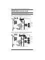
1
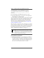
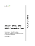
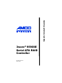
Quick Install Guide 3ware® 9590SE Serial ATA RAID Controller PN 720-0124-04 April 2006 Copyright ©2004-2006 Applied Micro Circuits Corporation (AMCC). All rights reserved. No part of this publication may be reproduced, stored in a retrieval system, or transmitted in any form by any means, electronic, mechanical, photocopying, recording or otherwise, without the proper written consent of AMCC, 215 Moffett Park Drive, Sunnyvale, CA 94089. Trademarks 3ware, Escalade, and 3DM are all registered trademarks of AMCC. The 3ware logo, 3BM, StorSwitch, TwinStor, and R5 Fusion are all trademarks of AMCC. All other trademarks herein are property of their respective owners. Disclaimer While every attempt is made to make this document as accurate as possible, AMCC assumes no responsibility for errors or omissions in this document, nor does AMCC make any commitment to update the information contained herein. Table of Contents Chapter 1. Installing an AMCC 3ware 9590SE RAID Controller 1 Before You Begin . . . . . . . . . . . . . . . . . . . . . . . . . . . . . . . . . . . . . . . . . . . . 2 Contents of Package . . . . . . . . . . . . . . . . . . . . . . . . . . . . . . . . . . . . . 2 Other Documentation . . . . . . . . . . . . . . . . . . . . . . . . . . . . . . . . . . . . . 2 Installation Considerations . . . . . . . . . . . . . . . . . . . . . . . . . . . . . . . . . 3 What You Need: Tools and Equipment . . . . . . . . . . . . . . . . . . . . . . . . 5 Safety Factors . . . . . . . . . . . . . . . . . . . . . . . . . . . . . . . . . . . . . . . . . . . . . . 5 Personal Safety . . . . . . . . . . . . . . . . . . . . . . . . . . . . . . . . . . . . . . . . . 5 Protecting Equipment and Data . . . . . . . . . . . . . . . . . . . . . . . . . . . . . 6 9590SE RAID Controller Cards . . . . . . . . . . . . . . . . . . . . . . . . . . . . . . . . . 8 Multilane Cables . . . . . . . . . . . . . . . . . . . . . . . . . . . . . . . . . . . . . . . . . . . 10 Installing a 9590SE RAID Controller . . . . . . . . . . . . . . . . . . . . . . . . . . . . 12 To connect the multilane cables to the controller . . . . . . . . . . . . . . . 12 To install the controller in the computer . . . . . . . . . . . . . . . . . . . . . . 13 To connect the multilane cables to the drives or backplane . . . . . . . 15 Connecting Drive Activity LED Indicators . . . . . . . . . . . . . . . . . . . . . . . . 16 Additional Details About the LED Status Connectors . . . . . . . . . . . . 18 Finishing Up . . . . . . . . . . . . . . . . . . . . . . . . . . . . . . . . . . . . . . . . . . . . . . . 20 Check Installation and Close the Case. . . . . . . . . . . . . . . . . . . . . . . 20 Configure your RAID Arrays . . . . . . . . . . . . . . . . . . . . . . . . . . . . . . . 20 Chapter 2. Installing the Battery Backup Unit . . . . . . . . . . . . 21 Tools and equipment required . . . . . . . . . . . . . . . . . . . . . . . . . . . . . . . . . Installation Overview . . . . . . . . . . . . . . . . . . . . . . . . . . . . . . . . . . . . . . . . Installation Instructions . . . . . . . . . . . . . . . . . . . . . . . . . . . . . . . . . . . . . . Replacing the Battery . . . . . . . . . . . . . . . . . . . . . . . . . . . . . . . . . . . . . . . 22 22 23 28 Appendix: Technical Support . . . . . . . . . . . . . . . . . . . . . . . . . 31 www.3ware.com iii iv 3ware 9590SE Serial ATA RAID Controller Quick Install Guide Chapter 1. Installing an AMCC 3ware 9590SE RAID Controller This chapter describes the physical installation of the AMCC 3ware 9590SE RAID controllers. It contains the following topics: “Before You Begin” provides important information about things you should consider before starting installation, and tools and equipment you will need. “Safety Factors” describes important precautions for your personal safety and to protect your equipment and data. Be sure to read this section. “Installing a 9590SE RAID Controller” and “Connecting Drive Activity LED Indicators” provide step-by-step instructions for installing a Serial ATA RAID controller. “Finishing Up” describes the final steps required when installing a serial controller. Chapter 2 (starting on page 21) includes information about how to install the Battery Backup Unit, model BBU-9550SX-01, on a 9590SE RAID controller. The BBU is an optional add-on, which can be purchased separately. www.3ware.com 1 Chapter 1. Installing an AMCC 3ware 9590SE RAID Controller Before You Begin Contents of Package 3ware 9590SE RAID controller This document, 3ware 9590SE Serial ATA RAID Controller Quick Install Guide. 3ware CD-ROM with drivers, software, and additional documentation. Multilane break-out cables (SFF-8087), for use with individual drives. Each cable supports up to four serial ATA drives. 2 cables are provided with the 8-port controller. 3 cables are provided with the 12-port controller. 4 cables are provided with the 16-port controller. Note: Double-ended multilane cables, for use with a multilane backplane, can be purchased separately. For details about these cables, see “Multilane Cables” on page 10. Important: Be sure to use AMCC/3ware certified cables with your 3ware RAID controller. Using an incorrect cable can result in drives that are not detected. For a list of available cables and associated part numbers, see http://3ware.com/products/ cables.asp. Other Documentation The following additional documentation is available for your 3ware 9590SE RAID Controller: 2 3ware 9590SE Serial ATA RAID Controller Quick Install Guide Before You Begin In PDF format, on the CD that came with your controller, and available through the 3ware website: 3ware Serial ATA RAID Controller User Guide 3ware 9000 Series Serial ATA RAID Controller CLI Guide In HTML format: Online help is available from 3DM 2 (3ware Disk Manager) Additional support information is available in the 3ware Knowledgebase, at this website: http://www.3ware.com/KB Installation Considerations Air Flow, Cable Length, and Routing Space Adequate airflow and ventilation are particularly important for 3ware 9590SE RAID controllers. The on-board heat sink collects heat, and must have adequate airflow in order to disburse it. It is important that the cables do not obstruct the air flow or prevent proper ventilation of the system. Selecting the Slot in Which to Install the Controller Consider these factors when deciding on the slot in which to insert the controller: 3ware 9590SE RAID controllers must be installed in PCI Express slots. They may be installed in PCI Express x4, x8, or x16 slots. Note that some desktop systems come with a PCI Express slot that has only one lane (x1). The 3ware 9590SE RAID controller cannot be installed in a PCI Express x1 slot. Warning! Do NOT insert the 9590SE controller into a PCI-X slot. Doing so could potentially damage the board or the system, and void the warranty. Cable routing may be easier if you install the 3ware RAID controller next to an open slot. www.3ware.com 3 Chapter 1. Installing an AMCC 3ware 9590SE RAID Controller Deciding Whether to Use the LED Status Connector 3ware RAID controllers include two types of LED status connectors: Overall indicator, which lights when any drive is active. Individual LED indicators, for each drive. (Not supported on chassis that have a common ground.) If you are building a system from scratch, you may want to consider using a chassis or drive carrier that is compatible with the 3ware RAID controller activity LEDs, such as the AMCC RDC-400SATA drive carrier, available through AMCC. Please check the 3ware web site for the Chassis Reference list (www.3ware.com/ products/compatibility_sata.asp). Most chassis have a single drive activity cable that you can connect to the overall activity indicator on the 3ware 9590SE controller. For the location of the overall drive activity connector, see the figure for the appropriate controller on page 16 and page 17, and refer to Table 1, “LED Indicator Pin Positions,” on page 18. Note: If you are using a chassis that includes a Chassis Control Unit (CCU), follow the instructions that came with the chassis to connect the I2C cable from the CCU to the I2C connector on the 9590SE. Drive Installation Considerations Selecting an enclosure. If you are planning to use RAID 1, 5, 10, or 50, you may want to consider installing drives into hotswappable enclosures, so that they can be easily removed in the event of a drive failure. For a discussion of RAID levels, see the 3ware Serial ATA RAID Controller User Guide. 4 3ware 9590SE Serial ATA RAID Controller Quick Install Guide Safety Factors When to install the drives. If the drives are not already installed in your computer, you can choose to install them either before or after installing the 9590SE controller. In either case, be sure to connect the SATA cable from the drive to the controller and connect the drive to power before turning on the system or you will not be able to see or configure the drives. What You Need: Tools and Equipment Tools Required You will need the following tools during installation: An ESD grounding strap or mat Standard hand tools to open your system’s case and install the 3ware RAID controller into an available PCI Express expansion slot. Often a Phillips screwdriver is all that is required. Safety Factors Be sure to follow the guidelines presented on the next few pages to insure your own safety, and that of your equipment. Personal Safety Warning! High voltages may be found inside computer equipment. Before installing any of the hardware in this package or removing the protective covers of any computer equipment, turn off power switches and disconnect power cords. Do not reconnect the power cords until the hardware is installed and the system cover is closed. Caution. Avoid contact with the heat sink if the system or server is in operation, as the heat sink will be very hot. The heat sink will be safe to touch after the server or system is powered down and the cover has been removed for a few minutes. www.3ware.com 5 Chapter 1. Installing an AMCC 3ware 9590SE RAID Controller Protecting Equipment and Data Backing Up Your Data Back up your data! Creating or deleting disk arrays destroys existing files on the member drives. If your drives contain valuable data, back them up and save the data elsewhere before attaching the drives to the controller. ESD (Electrostatic Discharge) Precautions To avoid damaging computer components and accessories when installing or removing the 3ware RAID controller, follow standard electrostatic discharge (ESD) precautions: When your computer case is open and its internal parts are exposed, do not touch any internal part unnecessarily. Always wear a grounded strap or work on an ESD-protective mat. Do not remove the 3ware RAID controller from its protective bag until you are properly grounded. Handle the 3ware RAID controller by its edges or by the black rail and metal bracket at its two ends. Do not touch any pin, contact, lead or component on the 3ware RAID controller. Things to Watch Out For Be careful when installing the 3ware RAID controller into your system. Excessive force can damage the board or your system. 6 Be sure you insert the board into a PCI Express slot, not a PCI-X slot. Be sure the board is aligned with its slot on the motherboard before installing. Do not flex the board excessively. Once the board is inserted into the PCI Express slot, make sure the board is seated correctly. If the board is not plugged in correctly, it will not work. 3ware 9590SE Serial ATA RAID Controller Quick Install Guide Safety Factors SATA cable connectors must be mated carefully with the connectors in the controller. The connectors provided are keyed to prevent you from inserting them upside-down. SATA cables are fragile and must not be crimped or pinched. Ensure that they do not impede the flow of cooling air from fans or heat sinks in the system case. Make sure that there is adequate air flow and ventilation around the 3ware 9590SE controller and its on-board heat sink. Warning! Do not replace the factory-installed heat sink shipped with the 3ware 9590SE RAID controller. Replacing the heat sink will alter thermal characteristics and cooling requirements and may cause the controller to fail. Replacing the factory-installed heat sink will void the warranty. www.3ware.com 7 Chapter 1. Installing an AMCC 3ware 9590SE RAID Controller 9590SE RAID Controller Cards Note: For details about LED connectors, see page 16. Figure 1. 8-Port 3ware 9590SE-8ML Serial ATA RAID Controller Slots for battery holder I2C connector LED Connectors Ports: 4 thru 7 0 thru 3 Heat sink BBU connector and hole for post Figure 2. 12-Port 3ware 9590SE-12ML Serial ATA RAID Controller Slots for battery holder I2C connector LED Connectors Ports: 8 thru 11 4 thru 7 0 thru 3 Heat sink 8 BBU connector and hole for post 3ware 9590SE Serial ATA RAID Controller Quick Install Guide 9590SE RAID Controller Cards Figure 3. 16-Port 3ware 9590SE-16ML Serial ATA RAID Controller Slots for battery holder I2C connector LED Connectors Ports: 12 thru 15 8 thru 11 4 thru 7 0 thru 3 Heat sink www.3ware.com BBU connector and hole for post 9 Chapter 1. Installing an AMCC 3ware 9590SE RAID Controller Multilane Cables Important: Be sure to use AMCC/3ware certified cables with your 3ware RAID controller. Using an incorrect cable can result in drives that are not detected. For a list of available cables and associated part numbers, see http://3ware.com/products/cables.asp. Three types of multilane cables can be used with 3ware 9590SE RAID controllers. Multilane breakout cables For use with a backplane that has individual SATA connectors or individual serial ATA drives, multilane breakout cables have an SFF-8087 multilane connector on one end and four individual SATA connectors on the other end. Note: This is the type of cable that ships with the 3ware 9590SE controller. Depending on the enclosure you are using, you may need to purchase a different cable to connect the 9590SE controller and the enclosure backplane Figure 4. Multi-lane Serial ATA Break-out Cable (SFF-8087) 10 3ware 9590SE Serial ATA RAID Controller Quick Install Guide Multilane Cables Multilane double-ended 4x cables For use with a multilane-enabled drive backplane that has the SFF-8087 mini SAS 4i connectors, these double-ended 4x cables have multilane connectors on each end. Figure 5. Multilane Cable Serial ATA (SFF-8087) Multilane converter cables To connect from a 3ware 9590SE RAID controller to a chassis that has SFF-8470 connectors on the backplane, use multilane converter cables, which have a SFF-8087 connector on one end and an Infini-band SFF8470 connector on the other end. Figure 6. Multilane SFF-8087 to SFF-8470 Serial ATA Converter Cable www.3ware.com 11 Chapter 1. Installing an AMCC 3ware 9590SE RAID Controller Installing a 9590SE RAID Controller 3ware 9590SE RAID controllers can be installed in a standard enclosure or in an enclosure with a backplane. Note: If you have a Battery Backup Unit (BBU), install it on the controller before proceeding. For details, see “Chapter 2. Installing the Battery Backup Unit”. To connect the multilane cables to the controller 1 Connect each multilane cable to a multilane connector on the controller. When the cable is inserted correctly, you will feel it click into place. Figure 7. Connecting a Multilane Cable with an SFF-8087 Connector to the 9590SE-16ML Controller Depending on the which model of the 9590SE you have, and the number of drives you will be connecting, you will connect between one and four multilane cables. The 9590SE-8ML comes with two multilane connectors, the 9590SE-12ML 12 3ware 9590SE Serial ATA RAID Controller Quick Install Guide Installing a 9590SE RAID Controller comes with three, and the 9590SE-16ML comes with four. Each cable supports up to four serial ATA ports. To install the controller in the computer 1 If the computer is running, shut it down. Turn off power to the computer and disconnect the power cord from the outlet. 2 Make sure you are properly grounded. (For details about safety precautions, see page 5.) 3 Open the computer case according to the manufacturer’s instructions. 4 Find the PCI Express slot you want to use for the 3ware 9590SE RAID controller. For a discussion of which slot to use, see “Selecting the Slot in Which to Install the Controller” on page 3. Warning! Make sure you select a PCI Express slot, not a PCI or PCI-X slot. Inserting a 9590SE into a PCI or PCI-X slot could potentially damage the board or system, and void the warranty of either the 9590SE or the motherboard. If you are uncertain about which slot to use, see the documentation for your system’s motherboard. 5 Remove the metal filler bracket for the slot. Save this screw; it will be used to secure the 3ware RAID controller after you have seated it in the slot. 6 Position the card in the PCI Express slot so that the contacts will mate with the grooves in the slot, and all pins make proper contact with the PCI Express slot pins when pushed into place. The 3ware 9590SE RAID controller will not fit in the one lane (x1) PCI Express slot. It will only work in the x4, x8, and x16 PCI Express slots. www.3ware.com 13 Chapter 1. Installing an AMCC 3ware 9590SE RAID Controller 7 Press down gently on the edge of the 3ware RAID controller directly above the PCI Express slot until it is fully seated. Figure 8. Inserting Controller Into PCI Express Slot Use a PCI Express slot for the 3ware 9590SE controller Do NOT use a PCI-X slot for the 3ware 9590SE controller 8 Check that the 3ware RAID controller’s metal bracket covers the hole in the case and secure the bracket with the screw that was used to secure the filler bracket in step 5. 9 When you tighten the screw on the bracket to the enclosure, make sure the card is not slanted in any direction; otherwise the card will not work properly. 14 3ware 9590SE Serial ATA RAID Controller Quick Install Guide Installing a 9590SE RAID Controller To connect the multilane cables to the drives or backplane 1 If your drives are not already installed, install them now, either by attaching them to the backplane, or by installing them in the computer chassis. If appropriate, set the PM2 (power management) jumper on the disk drives, to enable staggered spinup. Check the documentation that came with your disk drives to see whether this is required. 2 If your enclosure has a multilane drive backplane, connect the other end of each multilane cable to the backplane. If you are using a breakout cable, select one of the ends and plug it into each drive or drive carrier. One edge of each SATA cable connector is keyed to ensure proper installation. Figure 9. SATA End of Breakout Cable Connecting to Drive 3 Be sure that the power supply is connected to either the backplane or the individual drives, either by cable or through the drive carrier. 4 (Optional) Connect the drive activity LED connectors. For details, see page 16. 5 Turn to “Check Installation and Close the Case” on page 20. www.3ware.com 15 Chapter 1. Installing an AMCC 3ware 9590SE RAID Controller Connecting Drive Activity LED Indicators Connecting drive activity LED indicators is optional. For a discussion of whether to make these connections, see “Deciding Whether to Use the LED Status Connector” on page 4. Figure 10, 11, and 12 show the location of LED indicators on the different 9590SE controllers. Additional detail about these connectors starts on page 18. Figure 10. 8-Port 3ware 9590SE-8ML Serial ATA RAID Controller LED indicators for individual drives J7 is for drives 0, 1, 2, 3 (left to right) J8 is for drives 4, 5, 6, 7 (left to right) 16 Overall LED drive status indicator is the right-most LED header pin pair on each LED connector (J7 and J8). The anode is the lower of the two pins and the cathode is the upper. 3ware 9590SE Serial ATA RAID Controller Quick Install Guide Connecting Drive Activity LED Indicators Figure 11. 12-Port 3ware 9590SE-12ML Serial ATA RAID Controller LED indicators for individual drives J7 is for drives 0, 1, 2, 3 (left to right) J8 is for drives 4, 5, 6, 7 (left to right) J3 is for drives 8, 9, 10, 11 (left to right) Overall LED drive status indicator is the right-most LED header pin pair on each LED connector (J7, J8, and J3). The anode is the lower of the two pins and the cathode is the upper. Figure 12. 16-Port 3ware 9590SE-16ML Serial ATA RAID Controller LED indicators for individual drives J7 is for drives 0, 1, 2, 3 (left to right) J8 is for drives 4, 5, 6, 7 (left to right) J3 is for drives 8, 9, 10, 11 (left to right) J4 is for drives 12, 13, 14, 15 (left to right) www.3ware.com Overall LED drive status indicator is the right-most LED header pin pair on each LED connector (J7, J8, J9, J1). The anode is the lower of the two pins and the cathode is the upper. 17 Chapter 1. Installing an AMCC 3ware 9590SE RAID Controller Additional Details About the LED Status Connectors As shown in Figure 10 through Figure 12, LED connectors for individual drives are on J7, J8, J3, and J4 for the 16 port card, on J7, J8, and J3 for the 12-port cards, and on J7 and J8 for the 8-port. Pin 1 is located in the lower left-hand corner of each 10-pin connector. The odd-numbered pins, located on the bottom row, are 3.3V for the anode (+) side of each LED to be connected. The evennumbered pins are on the top or cathode (-) side. Table 1 summarizes the LED indicator pin positions for the different controllers. Warning: If using a chassis that has a common or shared LED ground, be sure to only connect LED cables to the anode pins on the controller. Do not connect any common ground to any cathode pins on the controller. Table 1: LED Indicator Pin Positions Controller 9590SE-8ML LED Header J7 J8 Pin Pair Comment : : : : : Orientation Horizontal 0 1 2 3 All Port number/All (all activity indicator) : : : : : Orientation Horizontal 4 5 6 7 All Port number / NU (Not Used) k-cathode-minus is on the top a-anode-plus is on the bottom 18 3ware 9590SE Serial ATA RAID Controller Quick Install Guide Connecting Drive Activity LED Indicators Table 1: LED Indicator Pin Positions Controller 9590SE-12ML LED Header J7 J8 J3 Pin Pair Comment : : : : : Orientation Horizontal 0 1 2 3 All Port number/NU (Not Used) : : : : : Orientation Horizontal 4 5 6 7 All Port number/NU (Not Used) : : : : : Orientation Horizontal 8 9 10 11 All Port number/All (all activity indicator) k-cathode-minus is on the top a-anode-plus is on the bottom 9590SE-16ML J7 J8 J3 J4 : : : : : Orientation Horizontal 0 1 2 3 All Port number/NU (Not Used) : : : : : Orientation Horizontal 4 5 6 7 All Port number/NU (Not Used) : : : : : Orientation Horizontal 8 9 10 11 All Port number/All (all activity indicator) : : : : : Orientation Horizontal 12 13 14 15 All Port number/All (all activity indicator) k-cathode-minus is on the top a-anode-plus is on the bottom www.3ware.com 19 Chapter 1. Installing an AMCC 3ware 9590SE RAID Controller Finishing Up After you have installed the controller in the computer and attached appropriate cables to the controller and drives, complete the following steps to complete the hardware installation. Check Installation and Close the Case 1 Verify that the cables do not interfere with the operation of any other components in the case or block the flow of cooling air. 2 Close the case and reconnect the power cables. Configure your RAID Arrays Turn to “First Time RAID Configuration” and “Configuring Units” in 3ware Serial ATA RAID Controller User Guide for information about configuring RAID arrays. The user guide is included on the 3ware CD that came with your controller. It is also available from the 3ware website at http://3ware.com/support/userdocs.asp. 20 3ware 9590SE Serial ATA RAID Controller Quick Install Guide Chapter 2. Installing the Battery Backup Unit The Battery Backup Unit model BBU-9550SX-01 is an add-on that can be attached to either the 3ware 9590SE or the 9550SX RAID controller to supply power to the memory module from an attached battery pack in the event of a system power loss. This allows the controller to use write-caching for optimal performance and not be exposed to data loss in the event of a system power failure. When fully charged, the battery preserves the contents of the controller cache memory for a limited period of time (up to 72 hours). When power is restored, cached data is flushed to disks. Caution: Both the 3ware RAID controller and the BBU are sensitive electronic equipment and can be damaged through electrostatic discharge. When installing the BBU on the controller, be sure you are grounded. Use a grounding strap, or work on an ESD-protective mat. Do not remove the 3ware controller or BBU from their protective bags until you are properly grounded. Handle the 3ware RAID controller by its edges or by the metal bracket at its end. Do not touch any pin, contact, lead, or component on the 3ware RAID controller. Important: The battery is a heat-sensitive component. The cooler the battery, the longer the battery lasts. If possible, place the controller with the BBU in a slot with good airflow, away from components that generate the most heat in the system, such as video cards. Note: The battery will drain if it is plugged into the BBU and there is no power to the unit. Wait to plug the battery into the BBU until the system is ready for use. www.3ware.com 21 Chapter 2. Installing the Battery Backup Unit Tools and equipment required Slot-head screwdriver Grounding strap Battery Backup Unit (BBU) and battery 3ware 9590SE series controller Installation Overview The Battery Backup Unit (BBU) is comprised of two pieces: the battery module and the BBU control module. These pieces attach to the controller at the points illustrated in Figure 13 and 14: a b c Clips on the battery module match to two slots on the top and one hole in the middle of the 3ware 9590SE RAID controller. Connector on the BBU mates to receptacle on the controller. Post on the BBU mates to post hole on the controller. Figure 13. Points of connection on the BBU a) Clips 22 b) BBU connector c) Post 3ware 9590SE Serial ATA RAID Controller Quick Install Guide Installation Instructions Figure 14. Points of connection on the full-height controller a) Hole and slots for the clips b) BBU receptacle c) Hole for post Installation Instructions 1 Remove the screw head from the plastic post on the BBU control module and set it aside (you will reattach it soon.) Figure 15. Removing the head from the plastic post www.3ware.com 23 Chapter 2. Installing the Battery Backup Unit 2 Position the BBU control module above the controller and align the BBU control module and the controller, making sure to: Mate the connector on the BBU control module with the receptacle on the controller. Match the plastic post on the BBU with the hole on the controller. Figure 16. BBU control module ready to connect to the controller 3 Press down gently until the BBU is seated. Figure 17. BBU control module connected to the controller 24 3ware 9590SE Serial ATA RAID Controller Quick Install Guide Installation Instructions 4 Turn the controller over, insert the plastic screw head that you removed in step 1 into the plastic post, and tighten it gently but firmly. (Do not over-tighten!) Warning! To avoid possible damage to the controller and the motherboard, make sure the module is connected in the proper orientation, and that the plastic post is attached. When the plastic post and the connector are attached correctly, the module is in the correct orientation. 5 Hook the clips on the top of the battery module over the slots on the top edge of the controller. Figure 18. Clips on the battery module hook over slots on the top edge of the controller www.3ware.com 25 Chapter 2. Installing the Battery Backup Unit Figure 19. Attaching the battery module 6 Press down gently on the top of the battery unit so that the battery holder flexes slightly and the clip on the bottom snaps into place in the lower hole. Figure 20. Pressing down gently on the battery unit flexes the holder slightly so that the bottom clip can be inserted 26 3ware 9590SE Serial ATA RAID Controller Quick Install Guide Installation Instructions 7 Insert the battery power connector into the power receptacle on the BBU. Note: The battery will drain if it is plugged in and there is no power to the unit. If the system will not be used right away, wait to do this step until the system is ready for use. Figure 21. Battery power connector inserted in power receptacle The controller is now ready to install in your system. www.3ware.com 27 Chapter 2. Installing the Battery Backup Unit Replacing the Battery The Battery Backup Unit (BBU) will last for many years. The battery has an expected life span of one to two years depending on usage. You can check the current status of the battery, and test it. For details, see instructions in the 3ware Serial ATA RAID Controller User Guide. Caution: There is a risk of explosion if the battery is replaced by an incorrect type. To obtain a replacement battery module, contact AMCC. For proper battery disposal resources, contact RBRC, the Rechargeable Battery Recycling Corporation (www.rbrc.com). Vorsicht: Es entsteht Explosionsgefahr bei Auswechslung der Baterie mit einer des falschen Typs. Um eine Ersatzbaterie zu erhalten, wenden Sie sich an die AMCC. Um Ressourcen zur korrekten Entsorgung der Baterie in Erfahrung zu bringen, wenden Sie sich an die RBRC (the Rechargeable Battery Recycling Corporation) (www.rbrc.com). To replace the battery 1 2 3 4 28 Make sure the system is powered down, that you are grounded, and follow all appropriate safety procedures. Remove the 3ware RAID controller from your system. Press down on the top of the battery module to free the clip on the bottom of the module. While pressing down on the top of the battery module, lift out the bottom of the battery module slightly. 3ware 9590SE Serial ATA RAID Controller Quick Install Guide Replacing the Battery 5 Once the bottom of the module is free, slide the module up to release the clips on the top. Figure 22. Removing the battery module a) Push the battery module down gently. b) Lift out the bottom of the battery module to release the clip from the bottom hole. c) Lift up to remove the clips on the top edge. Bottom clip 6 Disconnect the battery power cable from the BBU. To do so, press down on the lever-like clip on the battery power connector and slide it out of the slot. (If desired, you can remove the BBU control module to facilitate disconnecting the power cable.) Figure 23 shows a view of removing the power cable connection from the underside of the BBU control module. www.3ware.com 29 Chapter 2. Installing the Battery Backup Unit Figure 23. Removing the power cable from the BBU module Press down on the lever-like clip and pull the connector out. 7 If you removed the BBU control module in step 6, reattach it now. 8 Insert the new battery module that you received from AMCC and cable it up. 9 Reinstall the 3ware RAID controller, close up your system, and restart it. 10 Run a battery test to compute the estimated battery capacity of this new battery. You can run the battery test from the BBU page of either 3BM or 3DM 2, or by using the 3ware CLI. For detailed instructions, see the 3ware Serial ATA RAID Controller User Guide and the 3ware 9000 Series Serial ATA RAID Controller CLI Guide. 30 3ware 9590SE Serial ATA RAID Controller Quick Install Guide Appendix: Technical Support For support, troubleshooting tips, frequently asked questions, software releases, and compatibility information related to 3ware RAID controllers, refer to: 3ware support page at: http://www.3ware.com/support/ 3ware knowledgebase: http://www.3ware.com/KB/kb.asp 3ware software downloads: http://www.3ware.com/support/download.asp 3ware documentation: fhttp://www.3ware.com/support/userdocs.asp 3ware Compatibility Lists: http://www.3ware.com/support/sys_compatibility.asp For specific answers to questions or to give feedback about the product, visit our Web site at http://www.3ware.com/support and use our convenient e-mail form. AMCC also offers toll-free 1 (800) 840-6055 or 1 (408) 542-8800 direct phone support during normal business hours. Sales and ordering information For sales information, send an electronic mail message to [email protected]. Feedback on this manual Your feedback is welcome. If anything in the guide seems unclear please let us know by using the email form at http:// www.3ware.com/support. www.3ware.com 31