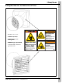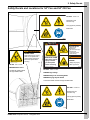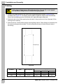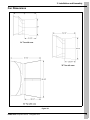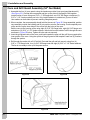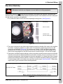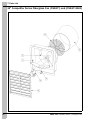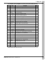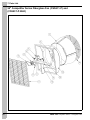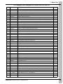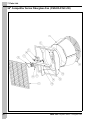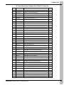
1
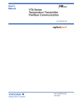
Competitor Series - Fiberglass Fans
Installation and Operation Manual
PNEG-1559
Date: 07-09-14
PNEG-1559
Congratulations
You have just purchased one of the best ventilation fans in the industry, designed to give years of
high velocity airflow while saving hundreds of dollars in electrical usage. Please take some time to
read through this manual and familiarize yourself with the proper installation methods and operation of
the fan.
FEATURES
• 30044 CFM and 20.2 CFM/W at 0.05" on 54" high performance.
• Limited lifetime warranty on the housing and cone.
• Corrosion resistant.
• Easy assembly and maintenance.
• On-site service and support.
Unpacking
Before beginning installation, check the condition of the fan. Remove the overwrap and packing materials
and examine all parts and components for shipping damage. Any damage incurred must be reported
immediately to the freight carrier.
Models : Competitor Series Fans
Size
2
: 24", 36" and 54"
PNEG-1559 Competitor Series - Fiberglass Fans
Table of Contents
Contents
Chapter 1 Safety .....................................................................................................................................................4
Safety Guidelines ...................................................................................................................................4
Safety Instructions ..................................................................................................................................5
General Safety Information ....................................................................................................................7
General Safety Statements ....................................................................................................................8
Chapter 2 Safety Decals ........................................................................................................................................9
Safety Decals and Locations for 24" Fan ...............................................................................................9
Safety Decals and Locations for 36" Fan .............................................................................................10
Safety Decals and Locations for 54" Fan and 54" CE Fan ..................................................................11
Chapter 3 Installation and Assembly .................................................................................................................12
Framing ................................................................................................................................................12
Fan Dimensions ...................................................................................................................................13
Cone and Grill Guard Assembly (54" Fan Model) ................................................................................14
Chapter 4 Electrical Wiring .................................................................................................................................15
Electrical Hook-Up ...............................................................................................................................15
54" 3 Phase 50 Hz CE Electrical Hook-Up ...........................................................................................16
Chapter 5 Start-Up and Maintenance .................................................................................................................17
Start-Up and Operation of the Competitor Series Fan .........................................................................17
Chapter 6 Troubleshooting Guide ......................................................................................................................18
Chapter 7 Parts List .............................................................................................................................................19
24" Competitor Series Fiberglass Fan (CS24C1) and (CS24C1-BLK) ................................................20
36" Competitor Series Fiberglass Fan (CS36C1) ................................................................................22
54" Competitor Series Fiberglass Fan (CS54C1-P) and (CS54C1-P-BLK) .........................................24
54" Competitor Series Fiberglass Fan (CS5435-E-NC-CE) .................................................................26
54" Competitor Series Fiberglass Fan (CS5435-P-NC-CE) .................................................................28
54" Competitor Series Fiberglass Fan (CS54C35-E-CE) .....................................................................30
54" Competitor Series Fiberglass Fan (CS54C35-P-CE) .....................................................................32
54" Competitor Series Fiberglass Fan (CS54C1-E) .............................................................................34
Chapter 8 Warranty ..............................................................................................................................................37
PNEG-1559 Competitor Series - Fiberglass Fans
3
1. Safety
Safety Guidelines
This manual contains information that is important for you, the owner/operator, to know and understand.
This information relates to protecting personal safety and preventing equipment problems. It is the
responsibility of the owner/operator to inform anyone operating or working in the area of this equipment
of these safety guidelines. To help you recognize this information, we use the symbols that are defined
below. Please read the manual and pay attention to these sections. Failure to read this manual and its
safety instructions is a misuse of the equipment and may lead to serious injury or death.
This is the safety alert symbol. It is used to alert you
to potential personal injury hazards. Obey all safety
messages that follow this symbol to avoid possible
injury or death.
DANGER
WARNING
WARNING indicates a hazardous situation which, if not
avoided, could result in death or serious injury.
CAUTION
CAUTION, used with the safety alert symbol, indicates a
hazardous situation which, if not avoided, could result in
minor or moderate injury.
NOTICE
NOTICE is used to address practices not related to
personal injury.
DC-2180
4
DANGER indicates a hazardous situation which, if not
avoided, will result in death or serious injury.
WARNING CE Fan models only. Safety decal applied
four (4) places.
PNEG-1559 Competitor Series - Fiberglass Fans
1. Safety
Safety Instructions
Our foremost concern is your safety and the safety of others associated with this equipment. We want to
keep you as a customer. This manual is to help you understand safe operating procedures and some
problems that may be encountered by the operator and other personnel.
As owner and/or operator, it is your responsibility to know what requirements, hazards, and precautions
exist, and to inform all personnel associated with the equipment or in the area. Safety precautions may be
required from the personnel. Avoid any alterations to the equipment. Such alterations may produce a very
dangerous situation where SERIOUS INJURY or DEATH may occur.
This equipment shall be installed in accordance with the current installation codes and applicable
regulations, which should be carefully followed in all cases. Authorities having jurisdiction should be
consulted before installations are made.
Install and Operate Electrical Equipment Properly
Electrical controls should be installed by a qualified electrician and
must meet the standards set by the National Electrical Code and all
local and state codes.
Disconnect and lock out all power sources before installing
wires/cables or servicing equipment.
Electric Shock Hazard
Keep Hands Away from Moving Parts
DO NOT put hand or arm in fan. Rotating parts can crush
and dismember.
DO NOT put any kind of tool inside fan to try and clear debris
while the fan is running. Damage to the equipment will result.
ALWAYS turn OFF and lock out all power sources before
servicing equipment.
Rotating Fan Blade
Lifting Hazard
Single person lift could cause injury.
Use two or more people or a mechanical lifting device
to lift/move heavy equipment.
Use Assistance When Lifting
or Moving Heavy Equipment
PNEG-1559 Competitor Series - Fiberglass Fans
5
1. Safety
Prepare for Emergencies
Be prepared if fire starts.
Keep a first aid kit and fire extinguisher handy.
Keep emergency numbers for doctors, ambulance service,
hospital, and fire department near your telephone.
Keep Emergency Equipment
Quickly Accessible
Wear Protective Clothing
Wear close-fitting clothing and safety equipment appropriate
to the job.
Eye Protection
Remove all jewelry.
Gloves
Tie long hair up and back.
Wear safety glasses at all times to protect eyes from debris.
Wear gloves to protect your hands from sharp edges on plastic
or steel parts.
Wear steel-toed boots to help protect your feet from falling
debris. Tuck in any loose or dangling shoestrings.
Steel-Toed Boots
Respirator
A respirator may be needed to prevent breathing potentially
toxic fumes and dust.
Wear a hard hat to help protect your head.
Hard Hat
Wear appropriate fall protection equipment when working at
elevations greater than six feet (6').
Fall Protection
6
PNEG-1559 Competitor Series - Fiberglass Fans
1. Safety
General Safety Information
Users Manual
This manual contains information and instructions essential to the safe installation and use of the
Competitor Series Fans. This manual should be read thoroughly before attempting any installation or use
of the fan. Keep this manual in a location that it can be readily accessable. Failure to read the manual and
its safety instructions constitutes misuse of the product.
Safety in Handling the Competitor Series Fans
This unit should be installed and maintained by a qualified technician familiar with the use and function of
ventilation fans. This will prevent situations leading to damaged components and/or injury. Whenever
possible, use mechanical lifting equipment when lifting or moving the fan during installation. When manual
handling is required, seek assistance from other people.
Correct Use of Your Competitor Series Fan
The fan is designed solely for the purpose of ventilating agricultural buildings. Use of the fan in any other
way is a misuse of the equipment and may endanger your’s or another person’s safety and health.
In the installation and use of the fan, only genuine AP/Cumberland parts are to be used. Use of other
non-genuine parts is a misuse and may lead to dangerous situations.
This fan is not designed for use in atmospheres where the risk of explosion is foreseen. Such
environments may include enclosed areas of high dust concentrations, gas, vapors and fumes. Use in
such an environment is prohibited. If in doubt, contact AP/Cumberland or your dealer.
Safety Guards
The fan contains moving and electrical parts which will cause serious injury, even death if touched. Guards
are placed on the fan to protect you. Operating the fan at any time with guards removed or incorrectly fitted
is a serious misuse of the fan and endangers you and other’s safety.
Safety in Maintenance
While the fan is designed to keep maintenance to a minimum, some items such as greasing the bearings
and belt replacement will be required over the life of the fan. Do not attempt any maintenance or repairs
on the fan unless you are competent to do so. Remember that the fan may, in certain situations, operate
under automatic control and will start without warning. Never attempt any work on the fan without first
isolating it from the power supply and locking out the isolator so that only you can turn the power back ON.
For your safety, follow the guidelines given in the Maintenance Section on Page 17 of this manual.
Before re-starting the fan, ensure that all electrical enclosures are locked, closed and all guards
and other safety measures are correctly fitted. If in doubt, contact your dealer or AP/Cumberland
for assistance.
PNEG-1559 Competitor Series - Fiberglass Fans
7
1. Safety
Electrical Safety
Provisions for an adequate and safe power supply to the fan unit are essential to your safety.
AP/Cumberland recommends that a competent and qualified electrician undertake all electrical wiring. All
wiring is to be installed in accordance with National, State and Local Electrical Codes.
Fans used to ventilate livestock buildings and other rooms where continuous air movement is essential,
should be connected to individual electrical circuits with a minimum of two (2) circuits per room.
We strongly recommend the installation of supplementary natural ventilation as well as a back-up
thermostat. There should also be an alarm system on at least one cooling stage. For connection
requirements, refer to the diagram on the motor nameplate and also to information enclosed with the fan
control used.
For 1 phase fans, motor overload protection should be provided for each fan. A circuit breaker or slow blow
motor type fuse must be used. A safety cut-off switch should be located adjacent to each fan. Contact your
local distributor for the correct cut-off switch.
The motor must be securely and adequately grounded. This can be accomplished by wiring with a
grounded conduit or a separate ground wire attached to the motor’s ground lug. Do not attempt operation
unless the motor is sufficiently grounded.
Do not kink power cable and never allow cable to come in contact with oil, grease, hot surfaces
or chemicals.
Remember, electrical safety is your responsibility.
General Safety Statements
READ THESE INSTRUCTIONS BEFORE INSTALLATION, OPERATION AND SERVICE
SAVE FOR FUTURE REFERENCE
1. Read and understand this operating manual before trying to install or operate the Competitor
Series Fans.
2. Power supply should be OFF and LOCKED OUT for service of electrical components. Use CAUTION
in checking voltage or other procedures requiring power to be ON.
3. Never attempt to operate the fan by jumping or otherwise bypassing any safety devices on the unit.
4. Keep the fan clean. Do not allow debris to collect around motors, belts, pulleys or bearings.
5. Use CAUTION in working around the fan’s moving parts.
8
PNEG-1559 Competitor Series - Fiberglass Fans
2. Safety Decals
Safety Decals and Locations for 24" Fan
DANGER
DC-1540 - 3-3/4" x 5-3/4"
Blade may start
automatically.
May cause serious injury.
DANGER High Voltage
Disconnect and
lockout power sources
before servicing.
WARNING Stay Clear of
Rotating Blade
WARNING Flying Objects Hazard
Located left middle outside and
right middle inside.
WARNING
STAY CLEAR OF
ROTATING BLADE
HIGH VOLTAGE
Will cause serious
injury or death.
Lockout power
before servicing.
The GSI Group 217-226-4421
PNEG-1559 Competitor Series - Fiberglass Fans
WARNING
FLYING OBJECTS
HAZARD
Danger of eye injury.
Wear eye protection.
DC-1540
9
2. Safety Decals
Safety Decals and Locations for 36" Fan
DANGER
WARNING
STAY CLEAR OF
ROTATING BLADE
Blade may start
automatically.
May cause serious injury.
DC-1540 - 3-3/4" x 5-3/4"
DANGER High Voltage
Disconnect and
lockout power sources
before servicing.
WARNING Stay Clear of
Rotating Blade
WARNING Flying Objects Hazard
Located left middle outside and
right middle inside.
HIGH VOLTAGE
Will cause serious
injury or death.
Lockout power
before servicing.
The GSI Group 217-226-4421
10
WARNING
FLYING OBJECTS
HAZARD
Danger of eye injury.
Wear eye protection.
DC-1540
PNEG-1559 Competitor Series - Fiberglass Fans
2. Safety Decals
Safety Decals and Locations for 54" Fan and 54" CE Fan
DC-2180 - 4-1/2" x 4"
Required on CE
54" fans only.
Two (2) pieces (outside)
Both sides.
DC-2180
DANGER
WARNING
STAY CLEAR OF
ROTATING BLADE
Blade may start
automatically.
May cause serious injury.
WARNING
Disconnect and
lockout power sources
before servicing.
SHEAR POINT
Keep hands clear of moving
parts. Do not operate with
guard removed. Disconnect
and lockout power before
servicing.
GSI Group Inc. 217-226-4421
DC-995
DC-995 - 2.0" x 4-1/2"
WARNING
HIGH VOLTAGE
FLYING OBJECTS
HAZARD
Will cause serious
injury or death.
Lockout power
before servicing.
Danger of eye injury.
Wear eye protection.
The GSI Group 217-226-4421
DC-1540
WARNING Shear Point
Located left middle outside
and right middle inside.
DC-1540 - 3-3/4" x 5-3/4"
DANGER High Voltage
WARNING Stay Clear of Rotating Blade
WARNING Flying Objects Hazard
Located left middle outside and right middle inside.
DC-2180 - 4-1/2" x 4"
Required on CE
54" fans only.
Two (2) pieces (inside)
Both sides.
DC-2180
PNEG-1559 Competitor Series - Fiberglass Fans
11
3. Installation and Assembly
Framing
Lifting hazard. Single person lift could cause injury. Use two (2) or more people
CAUTION or a mechanical lifting device to lift/move heavy equipment.
1. Construct the opening frame to the correct size (rough openings are listed in Chart below) as
illustrated in the Figure 3A. The framing must be able to support the weight of the fan assembly.
Ensure the load-bearing portion of the bottom sill is rigid and properly supported.
2. Position the fan in front of the opening from the inside. Using a minimum of two (2) people, lift fan
housing into the opening.
3. Check the fan for vertical position before screwing flanges down. Fasten flanges to framework with
the wood mounting screws provided. The fan housing should now be flush and level inside of
the framing.
Figure 3A
Outside Height (A)
Fan Model
12
Width
Inside Height (B)
4" Wall
6" Wall
8" Wall
CS24
34-1/2"
34-1/2"
33-1/2"
33"
32-1/2"
CS54
58"
60-1/2"
60"
59-1/2"
59
PNEG-1559 Competitor Series - Fiberglass Fans
3. Installation and Assembly
Fan Dimensions
Figure 3B
PNEG-1559 Competitor Series - Fiberglass Fans
13
3. Installation and Assembly
Cone and Grill Guard Assembly (54" Fan Model)
1. Assemble the four (4) cone panels using the hardware provided (use cone/guard hardware kit).
(See Figure 3C.) Overlap the cone panels and line up the slots on the flanges. Bolt together
outside portion of cone using one 5/16" x 1" SS flange bolt, one 5/16" SS flange nut and two (2)
5/16" x 1-1/2" fender washers per hole. Only install hardware in outside two (2) rows of holes.
Use washers on both sides to prevent cracking fiberglass panels.
2. When complete, the cone assembly should look like the cone in Figure 3D. Once assembled, position
cone assembly outside the building and lift into position onto the fan housing. Push completely onto
orifice and line up the inner holes of the orifice with the holes of the cone.
Bolt the cone to the housing orifice using eight (8) 5/16" SS flange bolts, eight (8) 5/16" flange nuts
and sixteen (16) 5/16" x 1-1/2" fender washers. Insert bolts from the inside of orifice through the cone
as shown in Figure 3E below. Tighten all bolts and nuts securely.
3. Insert the grill guard inside of the cone, push back towards the prop until the grill fits snug against the
inner portion of the cone. Using the eyelets of the grill guard as the template, mark four (4) locations
through the eyelets.
4. Drill through the marks with a 5/16" drill bit. Re-install the grill and bolt securely using four (4)
5/16" x 1" SS flange bolts, four (4) 5/16" SS flange nuts and eight (8) 5/16" x 1-1/4" fender washers.
The fan is now ready to wire up to the power source.
Figure 3C
Figure 3D
Figure 3E
14
PNEG-1559 Competitor Series - Fiberglass Fans
4. Electrical Wiring
Electrical Hook-Up
Disconnect and lock out all power sources before servicing equipment.
DANGER
As previously mentioned, All wiring should be installed in accordance with National, State and Local
Electrical Codes. A certified electrician should complete this portion of the installation to ensure safety and
that the wiring is correct for the application.
1. First, remove the back cover of the motor exposing the wiring block. (See Figure 4A.)
Ground lug
Hole for conduit
Gusset for wire
(remove rubber plug)
Figure 4A
2. The motor is designed to use either a solid clamping conduit on the side of the motor or the supplied
wire with a 3 prong plug attached. In either case, it is important to attach the ground wire to the
ground lug as depicted in Figure 4A. For correct motor rotation (CCW), the Red wire should be
located on the L2 connection as depicted. If this is not the case, switch the Red and Black wires.
Refer to the wiring diagram on the side of the motor for correct wiring for 115V and 230V supply.
3. Fans used to ventilate livestock buildings or other rooms where continuous air movement is essential
should be connected to individual electrical circuits with a minimum of two (2) circuits per room. For
connection requirements, refer to diagram on the motor nameplate. For 1 phase fans, motor overload
protection should be provided for each fan. A safety cut-off switch should be located next to each fan.
A circuit breaker switch or slow blow motor type fuses must be used. (See Figure 4B.) 3 Phase fans
require three (3) pole contactors with overload protection.
Figure 4B
PNEG-1559 Competitor Series - Fiberglass Fans
15
4. Electrical Wiring
54" 3 Phase 50 Hz CE Electrical Hook-Up
CE Fan Electrical Connections (For 54", 3 Phase, 50 Hz Fiberglass CE
Fans Only.)
1. 3 Phase supply only.
2. Electrical supply protection fuses (not supplied).
3. Motor contactor (not supplied) with fused control voltage via fan control switch or control system
(not supplied).
4. Motor overload breaker (not supplied).
5. Service disconnect (not supplied).
Figure 4C 3 Phase Only
Energize the fan and note the direction of rotation. The prop should turn counterclockwise when viewed
from inside the house. If not switch the L1 lead with either the L2 or L3 and rotation will be corrected upon
re-energizing fan.
16
PNEG-1559 Competitor Series - Fiberglass Fans
5. Start-Up and Maintenance
Start-Up and Operation of the Competitor Series Fan
Disconnect and lock out all power sources before servicing equipment.
DANGER
1. With the fan de-energized, rotate the prop and look for clearance between the prop tip and the
housing. Check all fasteners to ensure they are tight. When satisfied, energize the fan and make note
of direction of rotation. The prop should turn counterclockwise when viewed from inside the house.
If not, refer back to Figure 4A on Page 15 and switch the Black and Red wires as noted after
de-energizing the fan. When satisfied the fan is operating properly, turn OFF power and insert the
shutters into the housing. Rotate the button retainers to lock down the shutters.
2. Write down the date that the fan went into service and follow the maintenance schedule as
listed below:
a. For belt driven fans, check the belt, pulleys and the bearings after every two (2) months of
service. Take note of the belt position in the pulleys; make sure it is slightly raised or flush with
the pulley. If recessed into the grooves, replace the belt.
b. The motor and shaft bearings are lubricated at the factory. The motor bearings should never
require lubrication over the life of the fan. Pillow block bearings should be re-lubricated every
30 operating days and/or after each wash down cycle with three (3) shots of grease or until
fresh grease is seen purging past seal. Lithium or lithium-complex based #2 NLGI grease must
be used. Other types of grease are incompatible with the factory lubricant and will damage
the bearing.
DO NOT use a pneumatic or powered grease gun.
CAUTION
Incompatible grease or lack of service will void bearing warranty.
3. When cleaning the fans, Do Not Spray bearings, tensioner or motor directly with a pressure washer
as this Will lead to premature failure of these components. After cleaning the fan, simply wipe these
parts with a clean rag to remove dirt and debris. Failure to follow these instructions will void the
warranty on these components.
4. While doing fan maintenance, inspect fasteners to ensure they are snug and have not vibrated loose.
Tighten as necessary.
PNEG-1559 Competitor Series - Fiberglass Fans
17
6. Troubleshooting Guide
Symptom
Probable Cause(s)
Corrective Action(s)
Defective motor bearing.
Replace.
Defective pillow block bearing.
Replace.
Parts are not securely anchored.
Check all bolts, screws and fasteners.
Damaged fan blade.
De-energize fan. Turn prop and check tip
clearance. Do they appear to be approximately the
same? (NOTE: They can be a little different without
any problems.) If they are significantly different,
contact your distributor for more information.
Electricity is turned OFF.
Contact local utility supplier.
Belt is broken.
Replace.
Defective motor.
Replace.
Open power supply circuit.
Replace fuse or reset circuit breaker. Check for
disconnected, cut or damaged power cord.
Intake/exhaust shutter is jammed/clogged.
Repair/replace/clean as necessary.
Inlet/outlet guards clogged by dirt/debris.
Repair/replace/clean as necessary.
Voltage supplied is not correct (must be
within ±10% of the nominal voltage).
Check line voltage at motor, verify wiring. Check with
local utility supplier for possible line problems.
Fan blade has excessive dirt build-up.
Clean unit.
Motor/drive shaft is bent.
Replace.
Fan blade is bent or otherwise damaged.
Replace blade. Recoat shaft with anti-seize lubricant.
Intake/exhaust shutter is jammed/clogged
Repair/replace/clean as necessary.
Inlet/outlet guards clogged by dirt/debris.
Repair/replace/clean as necessary.
Motor has excessive dirt build-up.
Clean unit.
Fan blade has excessive dirt build-up.
Clean unit.
Building operating static pressure too high.
Adjust air inlets to lower static pressure.
Power supply voltage is too low.
Check line voltage at motor; verify wiring is of
sufficient gauge for load and length of conductor.
Check with local utility supplier for possible
line problems.
Excessive noise.
Fan inoperative.
Insufficient airflow.
Excessive vibration.
Motor overheats and
nuisance trips.
18
PNEG-1559 Competitor Series - Fiberglass Fans
7. Parts List
1. 24" Competitor Series Fiberglass Fan (CS24C1) and (CS24C1-BLK) (See Pages 20 and 21.)
2. 36" Competitor Series Fiberglass Fan (CS36C1) (See Pages 22 and 23.)
3. 54" Competitor Series Fiberglass Fan (CS54C1-P) and (CS54C1-P-BLK) (See Pages 24 and 25.)
4. 54" Competitor Series Fiberglass Fan (CS5435-E-NC-CE) (See Pages 26 and 27.)
5. 54" Competitor Series Fiberglass Fan (CS5435-P-NC-CE) (See Pages 28 and 29.)
6. 54" Competitor Series Fiberglass Fan (CS54C35-E-CE) (See Pages 30 and 31.)
7. 54" Competitor Series Fiberglass Fan (CS54C35-P-CE) (See Pages 32 and 33.)
8. 54" Competitor Series Fiberglass Fan (CS54C1-E) (See Pages 34 and 35.)
PNEG-1559 Competitor Series - Fiberglass Fans
19
7. Parts List
24" Competitor Series Fiberglass Fan (CS24C1) and (CS24C1-BLK)
20
PNEG-1559 Competitor Series - Fiberglass Fans
7. Parts List
24" Competitor Series Fiberglass Fan (CS24C1) and (CS24C1-BLK) Parts List
Ref #
Part #
Description
Qty
1
12-0083F*
Housing, APP-24" Fiberglass
1
2
PS-32C*
Shutter, PVC APP-24"
1
3
15-0083
Motor, 1/3 HP, 1100 RPM, 1 PH, 115V/230V
1
4
11-0181
APP-24" Motor Mount
1
4
11-0218
24" APP Fan, Motor Mount Left Half
1
4
11-0219
24" APP Fan, Motor Mount Right Half
1
4
S-7176
Huck Bolt 1/4" x 2" Magnagrip
2
4
S-7177
Collar Huck 1/4" Magnagrip
2
5
12-0080F*
Cone, APP-24 Fiberglass Discharge
1
6
11-0202-WH*
Guard, Grill for APP-24" Fan PTD White
1
7
13-0147
Propeller, 5 Blade - Torque Decal Attached
1
7
10-0097
Shutter Mount Hardware
1
7
91-0042
Button, Turn Plastic Large Tongue
8
7
FH-1309
Lock Nut 1/2" with Pipe Threads
1
7
FH-1310
Cord Connector, Heyco #3231
1
7
S-7279
Flat Washer 3/16" I.D. (Backup Washer for 3/16" Rivets)
8
7
S-7419
Screw, SDS #10-16 x 1-1/4" HWH SS410
8
7
S-7502
Screw, SMSA 1/4"-14 x 1-1/2" HWHS SS
8
7
DC-1540
Decal, Danger/Warning
2
7
S-7005
Flat Washer 5/16" SS
8
7
S-7447
Flange Bolt 5/16"-18 x 1" SS (Full Thread)
10
7
S-8168
Flange Bolt 5/16"-18 x 1-1/2" SS
4
7
S-8452
Flange Nut 5/16"-18 SS Waxed
14
7
S-8724
Fender Washer 5/16" x 1-1/2" x 1/16" SS
6
7
PNEG-1559
Competitor Series Fan Operation/Instruction Manual
1
* For black fans add - BLK suffix to part numbers.
PNEG-1559 Competitor Series - Fiberglass Fans
21
7. Parts List
36" Competitor Series Fiberglass Fan (CS36C1)
22
PNEG-1559 Competitor Series - Fiberglass Fans
7. Parts List
36" Competitor Series Fiberglass Fan (CS36C1) Parts List
Ref #
Part #
Description
Qty
1
11-0203-WH
Guard Grill for APP-36" Fan PTD White
1
2
12-0091
Housing, APP-36 Fiberglass
1
3
15-0136
Motor for 36" Direct Drive Competitor
1
4
PS-42C
Shutter, PVC 42"
1
5
11-0370
Competitor Series 36" Fiberglass Fan AL Motor Mount Assembly
1
5
11-0364
Bracket - AL 36" Fiberglass Fan Motor Mount
1
5
11-0368
Bracket - AL 36" Fiberglass Fan Vertical Strut
1
5
S-7176
Huck Bolt 1/4" x 2" Magnagrip
2
5
S-7177
Collar Huck 1/4" Magnagrip
2
6
13-0148
Propeller, X Blade (X Diameter) Competitor Series 36"
1
7
12-0093
Cone, APP-36 Fiberglass Discharge
1
7
10-0105
Fiberglass Fan Shutter Mount Hardware
10
7
91-0042
Turn Button Plastic Large Tongue
12
7
FH-1309
Lock Nut 1/2" with Pipe Threads
1
7
FH-1310
Cord Connector, Heyco #3231
1
7
S-7279
Flat Washer 3/16" I.D. (Backup Washer for 3/16" Rivets)
12
7
S-7419
Screw, SDS #10-16 x 1-1/4" HWH SS410
12
7
S-7502
Screw, SMSA 1/4"-14 x 1-1/2" HWHS SS
8
7
DC-1540
Decal, Danger/Warning
2
7
S-7005
Flat Washer 5/16" SS
8
7
S-7447
Flange Bolt 5/16"-18 x 1" SS (Full Thread)
10
7
S-8168
Flange Bolt 5/16"-18 x 1-1/2" SS
4
7
S-8452
Flange Nut 5/16"-18 SS Waxed
14
7
S-8724
Fender Washer 5/16" x 1-1/2" x 1/16" SS
6
7
PNEG-1559
Competitor Series Fan Operation/Instruction Manual
1
PNEG-1559 Competitor Series - Fiberglass Fans
23
7. Parts List
54" Competitor Series Fiberglass Fan (CS54C1-P) and
(CS54C1-P-BLK)
24
PNEG-1559 Competitor Series - Fiberglass Fans
7. Parts List
54" Competitor Series Fiberglass Fan (CS54C1-P) and (CS54C1-P-BLK) Parts List
Ref #
Part #
Description
Qty
1
12-0259*
Cone, 54" Fiberglass Panel
4
2
13-0144RS
Propeller, 54" SST (Solid Rivets)
1
3
15-0131
Motor, 1-1/2 HP, 1 PH, 60 Hz, 1.5 SF
1
4
16-0016
Sheave, AK34 x 5/8" Groove
1
5
16-0099
Pulley, Fenner Nylon 104 x 1"
1
6
16-0088
Belt, AX 46 Cogged V-Belt, 48" Nominal Length
1
7
PS-59C*
Shutter PVC 59-1/4" Tall x 56-3/4" Wide
1
8
91-0057
Tensioner, Rotary Assembly with Splash Guards
1
9
16-0005
Drive Shaft, 1" Ground and Polished
1
10
11-0359
Vertical Strut - 54" Fiberglass Boss Fan
1
11
11-0358
Bearing Plate - 54" Fiberglass Boss Fan
1
12
1016-0100
1" Pillow Block Bearing
2
13
12-0258*
Housing, 54" Fiberglass
1
14
11-0255WH*
54" Fiberglass Fan Grill Guard 61" White
1
14
10-0100
54" Fiberglass Cone/Guard Hardware Kit
1
14
S-7447
Flange Bolt 5/16"-18 x 1" SS (Full Thread)
20
14
S-8452
Flange Nut 5/16"-18 SS Waxed
20
14
S-8724
Fender Washer 5/16" x 1-1/2" x 1/16" SS
40
14
DC-1540
Decal, Danger/Warning
2
14
DC-1571
Decal, Grease Instructions All BD Fans
1
14
DC-995
Decal, Warning Shear Point
1
14
S-7447
Flange Bolt 5/16"-18 x 1" SS (Full Thread)
10
14
S-8032
Flange Nut 3/8"-16 SS
6
14
S-8140
Flange Bolt 3/8"-16 x 1-1/2" SS
4
14
S-8452
Flange Nut 5/16"-18 SS Waxed
10
14
S-8724
Fender Washer 5/16" x 1-1/2" x 1/16" SS
6
14
S-9168
Square Key 1/4" x 1"
2
14
10-0105
Fiberglass Fan Shutter Mount Hardware
1
14
91-0042
Turn Button Plastic Large Tongue
12
14
FH-1309
Lock Nut 1/2" with Pipe Threads
1
14
FH-1310
Cord Connector, Heyco #3231
1
14
S-7279
Flat Washer 3/16" I.D. (Backup Washer for 3/16" Rivets)
12
14
S-7419
Screw, SDS #10-16 x 1-1/4" HWH SS410
12
14
S-7502
Screw, SMSA 1/4"-14 x 1-1/2" HWHS SS
8
14
1EL2046
Rubber Grommet
1
14
PNEG-1559
Competitor Series Fan Operation/Instruction Manual
1
* For black fans add - BLK suffix to part numbers.
PNEG-1559 Competitor Series - Fiberglass Fans
25
7. Parts List
54" Competitor Series Fiberglass Fan (CS5435-E-NC-CE)
26
PNEG-1559 Competitor Series - Fiberglass Fans
7. Parts List
54" Competitor Series Fiberglass Fan (CS5435-E-NC-CE) Parts List
Ref #
Part #
Description
Qty
1
12-0259
Cone, 54" Fiberglass Panel
4
2
13-0144RS
Propeller, 54" SST (Solid Rivets)
1
2A
13-0202
Propeller, 54" SST (For Six (6) Blade Propeller Only)
1
3
15-0200
Motor, 1-3/4 HP, 3 PH 208-230/460V, 50/60 Hz
1
4
16-0016
Sheave, AK34 x 5/8" Groove
1
017-1422-9
Sheave, AK30 x 5/8" (For Six (6) Blade Propeller Only)
1
5
16-0015
Sheave, 1 Grade, A8.78" - 1", 8.93" O.D.
1
5A
13-0203
Sheave, Al124 1.00" Bore x 1/4" Keyway (For Six (6) Blade Propeller Only)
1
6
16-0088
Belt, AX 46 Cogged V-Belt, 48" Nominal Length
1
6A
16-0110
Belt, AX 54, Cogged V Belt, 56" Nominal Length (For Six (6) Blade Propeller Only)
1
7
PS-59C
Shutter PVC 59-1/4" Tall x 56-3/4" Wide
1
8
91-0057
Tensioner, Rotary Assembly with Splash Guards
1
9
16-0005
Drive Shaft, 1" Ground and Polished
1
10
11-0359
Vertical Strut - 54" Fiberglass Boss Fan
1
11
11-0358
Bearing Plate - 54" Fiberglass Boss Fan
1
12
1016-0100
1" Pillow Block Bearing
2
13
12-0258
Housing, 54" Fiberglass
1
14
11-0255WH
54" Fiberglass Fan Grill Guard 61" White
1
14
10-0100
54" Fiberglass Cone/Guard Hardware Kit
1
4A
14
S-7447
Flange Bolt 5/16"-18 x 1" SS (Full Thread)
20
14
S-8452
Flange Nut 5/16"-18 SS Waxed
20
14
S-8724
Fender Washer 5/16" x 1-1/2" x 1/16" SS
40
14
DC-1540
Decal, Danger/Warning
2
14
DC-1571
Decal, Grease Instructions All BD Fans
1
14
DC-995
Decal, Warning Shear Point
1
14
S-7447
Flange Bolt 5/16"-18 x 1" SS (Full Thread)
10
14
S-8032
Flange Nut 3/8"-16 SS
6
14
S-8140
Flange Bolt 3/8"-16 x 1-1/2" SS
4
14
S-8452
Flange Nut 5/16"-18 SS Waxed
10
14
S-8724
Fender Washer 5/16" x 1-1/2" x 1/16" SS
6
14
S-9168
Square Key 1/4" x 1"
2
14
10-0105
Fiberglass Fan Shutter Mount Hardware
1
14
91-0042
Turn Button Plastic Large Tongue
12
14
FH-1309
Lock Nut 1/2" with Pipe Threads
1
14
FH-1310
Cord Connector, Heyco #3231
1
14
S-7279
Flat Washer 3/16" I.D. (Backup Washer for 3/16" Rivets)
12
14
S-7419
Screw, SDS #10-16 x 1-1/4" HWH SS410
12
14
S-7502
Screw, SMSA 1/4"-14 x 1-1/2" HWHS SS
8
14
1EL2046
Rubber Grommet
1
14
PNEG-1559
Competitor Series Fan Operation/Instruction Manual
1
PNEG-1559 Competitor Series - Fiberglass Fans
27
7. Parts List
54" Competitor Series Fiberglass Fan (CS5435-P-NC-CE)
28
PNEG-1559 Competitor Series - Fiberglass Fans
7. Parts List
54" Competitor Series Fiberglass Fan (CS5435-P-NC-CE) Parts List
Ref #
Part #
Description
Qty
1
12-0259
Cone, 54" Fiberglass Panel
4
2
13-0144RS
Propeller, 54" SST (Solid Rivets)
1
3
15-0200
Motor, 1-3/4 HP, 3 PH 208-230/460V, 50/60 Hz
1
4
16-0027
Sheave, 1 Grade, A3-1/2" - 5/8", 3-3/4" O.D.
1
5
16-0015
Sheave, 1 Grade, A8.78" - 1", 8.93" O.D.
1
6
16-0088
Belt, AX 46 Cogged V-Belt, 48" Nominal Length
1
7
PS-59C
Shutter PVC 59-1/4" Tall x 56-3/4" Wide
1
8
91-0057
Tensioner, Rotary Assembly with Splash Guards
1
9
16-0005
Drive Shaft, 1" Ground and Polished
1
10
11-0359
Vertical Strut - 54" Fiberglass Boss Fan
1
11
11-0358
Bearing Plate - 54" Fiberglass Boss Fan
1
12
1016-0100
1" Pillow Block Bearing
2
13
12-0258
Housing, 54" Fiberglass
1
14
11-0255WH
54" Fiberglass Fan Grill Guard 61" White
1
14
10-0100
54" Fiberglass Cone/Guard Hardware Kit
1
14
S-7447
Flange Bolt 5/16"-18 x 1" SS (Full Thread)
20
14
S-8452
Flange Nut 5/16"-18 SS Waxed
20
14
S-8724
Fender Washer 5/16" x 1-1/2" x 1/16" SS
40
14
DC-1540
Decal, Danger/Warning
2
14
DC-1571
Decal, Grease Instructions All BD Fans
1
14
DC-995
Decal, Warning Shear Point
1
14
S-7447
Flange Bolt 5/16"-18 x 1" SS (Full Thread)
10
14
S-8032
Flange Nut 3/8"-16 SS
6
14
S-8140
Flange Bolt 3/8"-16 x 1-1/2" SS
4
14
S-8452
Flange Nut 5/16"-18 SS Waxed
10
14
S-8724
Fender Washer 5/16" x 1-1/2" x 1/16" SS
6
14
S-9168
Square Key 1/4" x 1"
2
14
10-0105
Fiberglass Fan Shutter Mount Hardware
1
14
91-0042
Turn Button Plastic Large Tongue
12
14
FH-1309
Lock Nut 1/2" with Pipe Threads
1
14
FH-1310
Cord Connector, Heyco #3231
1
14
S-7279
Flat Washer 3/16" I.D. (Backup Washer for 3/16" Rivets)
12
14
S-7419
Screw, SDS #10-16 x 1-1/4" HWH SS410
12
14
S-7502
Screw, SMSA 1/4"-14 x 1-1/2" HWHS SS
8
14
1EL2046
Rubber Grommet
1
14
PNEG-1559
Competitor Series Fan Operation/Instruction Manual
1
PNEG-1559 Competitor Series - Fiberglass Fans
29
7. Parts List
54" Competitor Series Fiberglass Fan (CS54C35-E-CE)
30
PNEG-1559 Competitor Series - Fiberglass Fans
7. Parts List
54" Competitor Series Fiberglass Fan (CS54C35-E-CE) Parts List
Ref #
Part #
Description
Qty
1
12-0259
54" Fiberglass Cone Panel
4
2
13-0144RS
Propeller, 54" SST (Solid Rivets)
1
3
15-0200
Motor, 1-3/4 HP, 3 PH 208-230/460V, 50/60 Hz
1
4
16-0016
Sheave, AK34 x 5/8" Groove
1
5
16-0015
Sheave, 1 Grade, A8.78" - 1", 8.93" O.D.
1
6
16-0088
Belt, AX 46 Cogged V-Belt, 48" Nominal Length
1
7
PS-59C
Shutter PVC 59-1/4" Tall x 56-3/4" Wide
1
8
91-0057
Tensioner, Rotary Assembly with Splash Guards
1
9
16-0005
Drive Shaft, 1" Ground and Polished
1
10
11-0359
Vertical Strut - 54" Fiberglass Boss Fan
1
11
11-0358
Bearing Plate - 54" Fiberglass Boss Fan
1
12
1016-0100
1" Pillow Block Bearing
2
13
12-0258
Housing, 54" Fiberglass
1
14
11-0255WH
54" Fiberglass Fan Grill Guard 61" White
1
14
10-0100
54" Fiberglass Cone/Guard Hardware Kit
1
14
S-7447
Flange Bolt 5/16"-18 x 1" SS (Full Thread)
20
14
S-8452
Flange Nut 5/16"-18 SS Waxed
20
14
S-8724
Fender Washer 5/16" x 1-1/2" x 1/16" SS
40
14
DC-1540
Decal, Danger/Warning
2
14
DC-1571
Decal, Grease Instructions All BD Fans
1
14
DC-995
Decal, Warning Shear Point
1
14
S-7447
Flange Bolt 5/16"-18 x 1" SS (Full Thread)
10
14
S-8032
Flange Nut 3/8"-16 SS
6
14
S-8140
Flange Bolt 3/8"-16 x 1-1/2" SS
4
14
S-8452
Flange Nut 5/16"-18 SS Waxed
10
14
S-8724
Fender Washer 5/16" x 1-1/2" x 1/16" SS
6
14
S-9168
Square Key 1/4" x 1"
2
14
10-0105
Fiberglass Fan Shutter Mount Hardware
1
14
91-0042
Turn Button Plastic Large Tongue
12
14
FH-1309
Lock Nut 1/2" with Pipe Threads
1
14
FH-1310
Cord Connector, Heyco #3231
1
14
S-7279
Flat Washer 3/16" I.D. (Backup Washer for 3/16" Rivets)
12
14
S-7419
Screw, SDS #10-16 x 1-1/4" HWH SS410
12
14
S-7502
Screw, SMSA 1/4"-14 x 1-1/2" HWHS SS
8
14
1EL2046
Rubber Grommet
1
14
PNEG-1559
Competitor Series Fan Operation/Instruction Manual
1
PNEG-1559 Competitor Series - Fiberglass Fans
31
7. Parts List
54" Competitor Series Fiberglass Fan (CS54C35-P-CE)
32
PNEG-1559 Competitor Series - Fiberglass Fans
7. Parts List
54" Competitor Series Fiberglass Fan (CS54C35-P-CE) Parts List
Ref #
Part #
Description
Qty
1
12-0259
54" Fiberglass Cone Panel
4
2
13-0144RS
Propeller, 54" SST (Solid Rivets)
1
3
15-0200
Motor, 1-3/4 HP, 3 PH 208-230/460V, 50/60 Hz
1
4
16-0027
Sheave, 1 Grade, A3-1/2" - 5/8", 3-3/4" O.D.
1
5
16-0015
Sheave, 1 Grade, A8.78" - 1", 8.93" O.D.
1
6
16-0088
Belt, AX 46 Cogged V-Belt, 48" Nominal Length
1
7
PS-59C
Shutter PVC 59-1/4" Tall x 56-3/4" Wide
1
8
91-0057
Tensioner, Rotary Assembly with Splash Guards
1
9
16-0005
Drive Shaft, 1" Ground and Polished
1
10
11-0359
Vertical Strut - 54" Fiberglass Boss Fan
1
11
11-0358
Bearing Plate - 54" Fiberglass Boss Fan
1
12
1016-0100
1" Pillow Block Bearing
2
13
12-0258
Housing, 54" Fiberglass
1
14
11-0255WH
54" Fiberglass Fan Grill Guard 61" White
1
14
10-0100
54" Fiberglass Cone/Guard Hardware Kit
1
14
S-7447
Flange Bolt 5/16"-18 x 1" SS (Full Thread)
20
14
S-8452
Flange Nut 5/16"-18 SS Waxed
20
14
S-8724
Fender Washer 5/16" x 1-1/2" x 1/16" SS
40
14
DC-1540
Decal, Danger/Warning
2
14
DC-1571
Decal, Grease Instructions All BD Fans
1
14
DC-995
Decal, Warning Shear Point
1
14
S-7447
Flange Bolt 5/16"-18 x 1" SS (Full Thread)
10
14
S-8032
Flange Nut 3/8"-16 SS
6
14
S-8140
Flange Bolt 3/8"-16 x 1-1/2" SS
4
14
S-8452
Flange Nut 5/16"-18 SS Waxed
10
14
S-8724
Fender Washer 5/16" x 1-1/2" x 1/16" SS
6
14
S-9168
Square Key 1/4" x 1"
2
14
10-0105
Fiberglass Fan Shutter Mount Hardware
1
14
91-0042
Turn Button Plastic Large Tongue
12
14
FH-1309
Lock Nut 1/2" with Pipe Threads
1
14
FH-1310
Cord Connector, Heyco #3231
1
14
S-7279
Flat Washer 3/16" I.D. (Backup Washer for 3/16" Rivets)
12
14
S-7419
Screw, SDS #10-16 x 1-1/4" HWH SS410
12
14
S-7502
Screw, SMSA 1/4"-14 x 1-1/2" HWHS SS
8
14
1EL2046
Rubber Grommet
1
14
PNEG-1559
Competitor Series Fan Operation/Instruction Manual
1
PNEG-1559 Competitor Series - Fiberglass Fans
33
7. Parts List
54" Competitor Series Fiberglass Fan (CS54C1-E)
34
PNEG-1559 Competitor Series - Fiberglass Fans
7. Parts List
54" Competitor Series Fiberglass Fan (CS54C1-E) Parts List
Ref #
Part #
Description
Qty
1
12-0259
54" Fiberglass Cone Panel
4
2
13-0144RS
Propeller, 54" SST (Solid Rivets)
1
3
15-0131
Motor, 1-1/2 HP, 1 PH, 60 Hz, 1.5 SF
1
4
017-1391-6
Sheave, 2.8" O.D. x 5/8" I.D.
1
5
16-0099
Pulley, Fenner Nylon 104 x 1"
1
6
16-0088
Belt, AX 46 Cogged V-Belt, 48" Nominal Length
1
7
PS-59C
Shutter PVC 59-1/4" Tall x 56-3/4" Wide
1
8
91-0057
Tensioner, Rotary Assembly with Splash Guards
1
9
16-0005
Drive Shaft, 1" Ground and Polished
1
10
11-0359
Vertical Strut - 54" Fiberglass Boss Fan
1
11
11-0358
Bearing Plate - 54" Fiberglass Boss Fan
1
12
1016-0100
1" Pillow Block Bearing
2
13
12-0258
Housing, 54" Fiberglass
1
14
11-0255WH
54" Fiberglass Fan Grill Guard 61" White
1
14
10-0100
54" Fiberglass Cone/Guard Hardware Kit
1
14
S-7447
Flange Bolt 5/16"-18 x 1" SS (Full Thread)
20
14
S-8452
Flange Nut 5/16"-18 SS Waxed
20
14
S-8724
Fender Washer 5/16" x 1-1/2" x 1/16" SS
40
14
DC-1540
Decal, Danger/Warning
2
14
DC-1571
Decal, Grease Instructions All BD Fans
1
14
DC-995
Decal, Warning Shear Point
1
14
S-7447
Flange Bolt 5/16"-18 x 1" SS (Full Thread)
10
14
S-8032
Flange Nut 3/8"-16 SS
6
14
S-8140
Flange Bolt 3/8"-16 x 1-1/2" SS
4
14
S-8452
Flange Nut 5/16"-18 SS Waxed
10
14
S-8724
Fender Washer 5/16" x 1-1/2" x 1/16" SS
6
14
S-9168
Square Key 1/4" x 1"
2
14
10-0105
Fiberglass Fan Shutter Mount Hardware
1
14
91-0042
Turn Button Plastic Large Tongue
12
14
FH-1309
Lock Nut 1/2" with Pipe Threads
1
14
FH-1310
Cord Connector, Heyco #3231
1
14
S-7279
Flat Washer 3/16" I.D. (Backup Washer for 3/16" Rivets)
12
14
S-7419
Screw, SDS #10-16 x 1-1/4" HWH SS410
12
14
S-7502
Screw, SMSA 1/4"-14 x 1-1/2" HWHS SS
8
14
1EL2046
Rubber Grommet
1
14
PNEG-1559
Competitor Series Fan Operation/Instruction Manual
1
PNEG-1559 Competitor Series - Fiberglass Fans
35
NOTES
36
PNEG-1559 Competitor Series - Fiberglass Fans
8. Warranty
GSI Group, LLC Limited Warranty
The GSI Group, LLC (“GSI”) warrants products which it manufactures to be free of defects in materials and workmanship
under normal usage and conditions for a period of 12 months after sale to the original end-user or if a foreign sale,
14 months from arrival at port of discharge, whichever is earlier. The end-user’s sole remedy (and GSI’s only obligation)
is to repair or replace, at GSI’s option and expense, products that in GSI’s judgment, contain a material defect in materials
or workmanship. Expenses incurred by or on behalf of the end-user without prior written authorization from the GSI
Warranty Group shall be the sole responsibility of the end-user.
Warranty Extensions:
The Limited Warranty period is extended for the following products:
Product
AP Fans and Flooring
AP and Cumberland
Cumberland
Feeding/Watering
Systems
Warranty Period
Performer Series Direct Drive Fan Motor
3 Years
All Fiberglass Housings
Lifetime
0 to 3 years - no cost to end-user
All Fiberglass Propellers
Lifetime
3 to 5 years - end-user pays 25%
Flex-Flo/Pan Feeding System Motors
2 Years
Feeder System Pan Assemblies
5 Years **
Feed Tubes (1-3/4" and 2.00")
10 Years *
Centerless Augers
10 Years *
0 to 3 years - no cost to end-user
Watering Nipples
10 Years *
3 to 5 years - end-user pays 50%
Grain Systems
Grain Bin Structural Design
5 Years
Grain Systems
Farm Fans
Zimmerman
Portable and Tower Dryers
2 Years
Portable and Tower Dryer Frames and
Internal Infrastructure †
5 Years
* Warranty prorated from list price:
5 to 7 years - end-user pays 50%
7 to 10 years - end-user pays 75%
** Warranty prorated from list price:
† Motors, burner components
and moving parts not included.
Portable dryer screens included.
Tower dryer screens not included.
GSI further warrants that the portable and tower dryer frame and basket, excluding all auger and auger drive components,
shall be free from defects in materials for a period of time beginning on the twelfth (12th) month from the date of purchase
and continuing until the sixtieth (60th) month from the date of purchase (extended warranty period). During the extended
warranty period, GSI will replace the frame or basket components that prove to be defective under normal conditions
of use without charge, excluding the labor, transportation, and/or shipping costs incurred in the performance of this
extended warranty.
Conditions and Limitations:
THERE ARE NO WARRANTIES THAT EXTEND BEYOND THE LIMITED WARRANTY DESCRIPTION SET FORTH
ABOVE. SPECIFICALLY, GSI MAKES NO FURTHER WARRANTY OF ANY KIND, EXPRESS OR IMPLIED,
INCLUDING, WITHOUT LIMITATION, WARRANTIES OF MERCHANTABILITY OR FITNESS FOR A PARTICULAR
PURPOSE OR USE IN CONNECTION WITH: (I) PRODUCT MANUFACTURED OR SOLD BY GSI OR (II) ANY ADVICE,
INSTRUCTION, RECOMMENDATION OR SUGGESTION PROVIDED BY AN AGENT, REPRESENTATIVE OR
EMPLOYEE OF GSI REGARDING OR RELATED TO THE CONFIGURATION, INSTALLATION, LAYOUT, SUITABILITY
FOR A PARTICULAR PURPOSE, OR DESIGN OF SUCH PRODUCTS.
GSI shall not be liable for any direct, indirect, incidental or consequential damages, including, without limitation, loss of
anticipated profits or benefits. The sole and exclusive remedy is set forth in the Limited Warranty, which shall not exceed
the amount paid for the product purchased. This warranty is not transferable and applies only to the original end-user. GSI
shall have no obligation or responsibility for any representations or warranties made by or on behalf of any dealer, agent
or distributor.
GSI assumes no responsibility for claims resulting from construction defects or unauthorized modifications to products
which it manufactured. Modifications to products not specifically delineated in the manual accompanying the equipment at
initial sale will void the Limited Warranty.
This Limited Warranty shall not extend to products or parts which have been damaged by negligent use, misuse, alteration,
accident or which have been improperly/inadequately maintained. This Limited Warranty extends solely to products
manufactured by GSI.
Prior to installation, the end-user has the responsibility to comply with federal, state and local codes which apply to the
location and installation of products manufactured or sold by GSI.
9101239_1_CR_rev8.DOC
PNEG-1559 Competitor Series - Fiberglass Fans
(revised January 2014)
37
This equipment shall be installed in accordance with
the current installation codes and applicable
regulations, which should be carefully followed in all
cases. Authorities having jurisdiction should be
consulted before installations are made.
1004 E. Illinois St.
Assumption, IL 62510-0020
Phone: 1-217-226-4421
Fax: 1-217-226-4420
www.gsiag.com
AP/Cumberland is a part of GSI, a worldwide brand of AGCO Corporation.
Copyright © 2014 by
Printed in the USA
Group
CN-313227