1
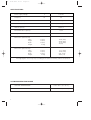
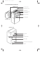
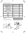
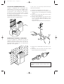
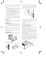
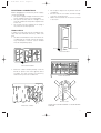
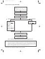
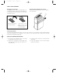
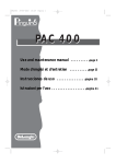
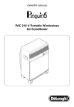
18-01-2001 12:12
Pagina 1
OWNERS’ MANUAL
O
N
O
F
F
AIR CONDITIONER PAC GSR/MU
I
GB
IMPORTANT: NOTE MAINTENANCE NEEDS ON PAGE 12
GB
18-01-2001 12:12
Pagina 2
IMPORTANT INFORMATION
When using electrical appliances, basic safety precautions should
always be followed, including the following:
- Read all instructions.
- To protect against fire, electrical shock and personal injury, do not
immerse cord, plug or appliance in water or other liquid.
- Close supervision is necessary when any appliance is used by or
near children.
- Do not operate with a damaged cord or plug, or after the appliance
malfunctions, or has been damaged in any manner. Return the
appliance to the nearest authorized service facility for examination,
repair or adjustment.
- The use of accessory attachments or spare parts not recommended
by the appliance manufacturer may result in fire, electrical shock or
personal injury.
- Do not use outdoors.
- Do not use the appliance for other than the intended use.
- Do not place any strain on the power cord. Avoid twisting and/or tangling.
- Ensure that outlet vent of exhaust hose is kept debris-clear and
obstruction free.
- Ensure that ventilation holes on the rear of the machine and front louvers are not blocked.
- The Pinguino should not be installed where the atmosphere could
contain combustible gases.
- Avoid using Pinguino in oily or sulphurous atmospheres or near sources of heat.
- Before moving the air-conditioner, empty water from collection tray.
- Do not place hot or heavy objects on the appliance.
- Clean air filter every week (see instructions at page 13).
- Unplug from outlet when not in use and before cleaning.
- To disconnect, turn any controll to “OFF” then remove plug from wall
outlet.
- Important: If you need to use an extension cord, please be sure to
use a heavy duty extension cord (minimum 14 gauge).
SAVE THESE INSTRUCTIONS
2
GB
18-01-2001 12:12
Pagina 3
Dear user,
We thank you for purchasing the
Pinguino air-conditioner and congratulate you on your wise choice.
For optimal results please read this
manual carefully before installing or
operating.
We know that the Pinguino will maintain your environment pleasingly
comfortable at all times.
With best wishes
De Longhi S.p.A.
If you have any questions about the operation
or service of your Pinguino, please call our
toll-free service number 1-800-322-3848.
or visit our internet site www.delonghiusa.com
for general overlook of De’Longhi group visit
www.delonghi.com
3
GB
18-01-2001 12:12
Pagina 4
SPECIFICATIONS
Power supply voltage
Frequency
V
Hz
110-120
60
Cooling capacity:
see rating label
Current consumption
see rating label
Air flow capacity
520 m3/h
Dehumidification capacity*
Length of hose
1,8l/h
feet/m
11/3.3
Dimensions (internal unit):
width
height
depth
weight
in.(mm)
in.(mm)
in.(mm)
lb./kg
18.03 (458)
33.46 (850)
15.74 (400)
44 (97)
Dimensions (external unit):
width
height
depth
weight
in.(mm)
in.(mm)
in.(mm)
lb./kg
17.71 (450)
18.50 (470)
8.26 (210)
30.87 (14)
*Average figures which may vary according to the ambient humidity and the temperature.
OPTIMUM OPERATING RANGE
4
OUTSIDE TEMPERATURE
69.8 - 95°F (21 - 35°C)
INSIDE TEMPERATURE
69.8 - 109°F (21 - 43°C)
18-01-2001 12:12
Pagina 5
ILLUSTRATED MAIN FEATURES LIST
INTERNAL UNIT
Connection hose
Control panel cover
O
F
F
GB
Control panel
Air vent control knob
Air outlet grille
Removable filter
Air intake grille
EXTERNAL UNIT
INTERNAL UNIT
Rear panel
Fuse
Carrying handle
Power cable
Condensation discharge tube
Castors
5
18-01-2001 12:12
Pagina 6
ILLUSTRATED ACCESSORY LIST
DESCRIPTION
INSTALLATION
Models without special couplings
The hose which connects the internal unit to the
external unit can be positioned in two ways:
a) Through a slightly-open window or door.
SUPPLIED
Wall bracket
2
Screws + wall plugs (ø 6mm)
4
Nut and bolt (ø 5mm)
4
Support belt with hook
2
Frame with connector hose
1
Castor stop
2
Condensation drainage
coupling
1
The appliance must be fitted at least 30
cm. from the surrounding walls.
b) Through a small hole (5.5 x 2.5 cm.) in the
lower part of the door or window frame. In
this case, it is necessary to use the special
frame for the connection hose.
frame for
hose
30
I
ON
OF
F
cm
OF
F
GB
cm
6
30
cm
30
18-01-2001 12:12
Pagina 7
ADJUSTABLE WINDOW BRACKET
In this case, it is necessary to disconnect the
internal unit as follows:
1) Remove the plug from the wall socket.
2) Remove the rear panel (on the back of the
appliance) by unscrewing the two retaining
screws.
3) Remove the metal brackets which fasten
the hose to the appliance.
4) Using a 24mm spanner, unscrew the union
on the coupling. When doing this, use a
19mm. spanner to block the extremity of the
hose in position.
Repeat this operation for the second union.
I
ON
OF
F
Pinguino is equipped with an adjustable window bracket. If you have a sash window, position the external unit outside the window, place
the bracket on the window sill, extend the
bracket fully within the window frame, making
the hose passing through the slot and lower
the window onto the bracket.
Thanks to the wing nut, it’s possible to use the window bracket also for sliding windows.
MODELS WITH SPECIAL COUPLINGS
If your air-conditioner is fitted with the special
rapid-fit coupling, the hose which connects the
internal unit to the external unit can also be
passed through a round hole in an external wall
(diameter: 6 cm. approx.).
F
5) Detach the condensation hose from its coupling.
6) Disconnect the electrical connector socket
by pressing the two retainer tabs.
OF
GB
ø6
cm
30
The path of the connector hose should be as
straight as possible, without sharp curves or
kinks.
7
18-01-2001 12:12
Pagina 8
To re-connect the ends of the connector hose
to the internal unit, repeat steps 1 to 6 in reverse order. The following precautions should be
observed:
• Before passing the connector hose through
the hole in the wall, the threaded ends of
the rapid couplings should be protected
using insulating tape or similar.
• Fit the two upper refrigerant couplings to the
two lower couplings and tighten by hand,
ensuring that they are correctly connected.
Then use the spanner to tighten fully.
• After connecting the two refrigerant couplings, fasten the brackets.
• Check that the refrigerant couplings are
sealed perfectly by wetting the couplings
with a little soapy water. No soap bubbles
should form.
In this case, use the special wall-mount brackets.
Alternatively, for temporary installation, the
external unit can be hung as shown in the figure. In this case, use the special support belts
(supplied with the appliance).
Attention
The external unit can be installed above or at
the same level as the internal unit, provided
that the difference in height between the two
units does not exceed 1.5 m.
The intake and outlet vents must not be
obstructed.
Leave a space of at least 6 cm. between the
rear of the unit and the wall.
Connection and disconnection of the refrigerant couplings should be carried out by qualified personnel.
INTERNAL UNIT
The internal unit should be installed in the room
to be conditioned. Generally, the ideal position
for the internal unit is under a window. In any
case, it should be positioned near an external
wall.
The internal unit must be perfectly leveled. If
necessary, use the castor stops supplied with
the machine.
The air intake and outlet grilles should not be
obstructed in any way.
EXTERNAL UNIT
The external unit can be positioned on a terrace or balcony. In this case, it is not necessary
to use the fixing brackets.
The external unit can also be mounted on a wall.
334
CONDENSATION DRAINAGE
The condensation which forms when the unit is
used for air-conditioning (i.e. in summer) evaporates from the external unit.
If the humidity is particularly high, it may be
necessary to fit the condensation discharge
tube (supplied with the machine). In this case,
fit the hose to the coupling on the bottom section of the external unit (remove the rubber cap
from the coupling).
When specific applications require it, the condensation drainage can be done directly from
the discharge pipe on the back of the unit.
Should this happen, water will be collected into
a tank and automatically removed through a
pump system. Such a pump has to be installed
separately and is available at any air conditioning contractors in your area.
Rubber cap
Ring
mm
Coupling
249 mm
GB
8
GB
18-01-2001 12:12
Pagina 9
ELECTRICAL CONNECTIONS
Before plugging the unit into the power supply,
check the following:
• the power supply voltage must be the same
as the voltage shown on the rating plate
• the power socket and the voltage circuit
must be suitable for the power requirements
of the unit
• the socket must be suitable for the plug; if
not, have the socket replaced.
•
•
•
Do not place objects of any kind on the airconditioner.
Ensure that the air intake and discharge
vents are not obstructed.
Make sure that there are no sources of heat
in the room.
FINAL CHECK
In order to ensure that your air-conditioner operates with the maximum efficiency, make sure
that:
• all doors and windows in the room to be airconditioned are closed (except for temporary installation, in which case a window
must be left partially open).
Close the door
Close the windows
•
Draw the curtains and/or partially close the
blinds to protect the room against direct
sunlight. This will increase the efficiency
and economy of the air-conditioner.
Lower the blinds
Do not cover
Draw the curtains
YOUR AIR-CONDITIONER IS NOW READY
FOR USE
9
GB
18-01-2001 12:12
Pagina 10
CONTROL PANEL
TIMER ON signal lamp
“Fan” signal lamp
“Alarm” warning light
“Air-conditioning” signal lamp
1
6
4
OFF
MIN
2
O
A
3
I
5
7
MAX
ON
B
C
Max. air-conditioning
signal lamp
D
Fan speed selection key
Thermostat knob
Timer notches
Min. air-conditioning
signal lamp
ON/OFF main switch key
Fan/conditioning selection key
Timer key
SETTING THE TIMER
The programmer/timer, like all clocks, must be
set to the exact time. If for example it is 4:00
p.m., turn the dial in a clockwise direction (following the direction of the arrow) until the number 4 (4 p.m.) is lined up with the arrow pointer
(the arrows indicates 4:00 p.m. approximately).
PROGRAMMED MODE
1) Release timer button B
.
2) Set the operating times by pushing out the
notches on the dial corresponding to the
period required (each notch represents 15
mins.).
3) Check that the timer indicates the correct
time (see instructions on setting).
Funzionamento
Operating
time
11
10
9
eg. from 9 to 11 a.m.
4
11
10
9
4
arrow pointer
N.B.: Never turn the dial in an anti-clockwise
direction!
The timer is in effect, an electric clock and
works only if the plug is connected to the
power supply. Whenever the plug is disconnected or there is a power failure, the programmer stops (the clock is then “slow”) and must
be re-set.
The unit can be used in either programmed or
non-programmed mode.
10
4) Select the desired function as shown in the
chart overleaf.
The unit will now switch on and off each
day at the selected times.
N.B: To override the programmed operating
times, simply press the ON/OFF timer key.
NON-PROGRAMMED MODE
1) B TIMER button must be pressed
2) Select the desired function as shown in the
chart on the following page.
GB
18-01-2001 12:12
Pagina 11
HOW TO START UP THE CONDITIONER
Plug the appliance into the wall
socket.
The ON/OFF signal lamp (1) comes
on and stays on for as long as the
appliance is connected to the socket.
Select either Programmed or Non-programmed mode (see previous page).
Select the fan speed required pressing
“Fan speed” key D.
VENTILATION
AIR-CONDITIONING
Key C (Ventilation/
Conditioning) must
be released
Turn the thermostat to
Max. cold.
Press
key
A
(ON/OFF)
Signal
lamp
5
(Conditioning) and
either 6 or 7 (Min. or
Max. fan speed) will
come on.
Key C (Ventilation/
Conditioning) must
be pressed
The appliance comes on.
If not, refer to pag. 14.
To switch off the appliance, press key A
(ON/OFF main switch).
N.B: the “TIMER ON” signal lamp will only come on with “Programmed” mode.
N.B:
For technical reasons, the temperature is not shown in degrees, but is represented by two lines
which vary in thickness according to the temperature. It is advisable to begin by turning the
thermostat to the maximum setting (thick green line = maximum cooling). When the room temperature is comfortable, turn the thermostat slowly away from the maximum heating or cooling
position until the air-conditioner switches off. Leave the thermostat in this position. The air-conditioner is now programmed to maintain the exact temperature at all Times.
This appliance is fitted with a special safety circuit. When the compressor switches off, this circuit prevents it from switching on again for at least 3 minutes.
11
18-01-2001 12:12
Pagina 12
MAINTENANCE
I
ON
OF
F
PRECAUTIONS
During cleaning and normal maintenance operations
remember to disconnect plug.
¢¢
,,
QQ
,,
QQ
¢¢
Under no circumstances should appliance be
washed with running water. Damage could be
caused to the electrical circuit.
O
N
O
FF
Never use petrol, gas, alcohol or solvents for
cleaning. Never spray insecticides or similar
products on the appliance, as these may
seriously damage the paintwork and plastic.
I
ON
OF
F
CLEANING OF EXTERNAL HOUSING
I
Clean with a damp cloth and dry thoroughly
with a clean dry cloth.
ON
OF
F
CONTROLS AT THE BEGINNING OF THE SEASON
I
GB
Carefully follow installation procedure.
12
Check for any defects in
power cord and plug.
18-01-2001 12:12
Pagina 13
AIR FILTER CLEANING
Maintenance of air filter
A clogged air filter reduces the quantity of circulating air and the efficiency of the appliance.
It is therefore recommended to clean the filter
at weekly intervals.
Removal and replacement of air filter
Gently pull filter upwards (as shown in figure).
Push to replace.
FF
filter
O
GB
Remove dust with a
vacuum cleaner
If the filter is very
dirty, wash it in
lukewarm water and
rinse thoroughly.
Cleaning procedure
To remove dust deposited on filter, use a vacuum cleaner. If it is very dirty, soak in lukewarm water
and rinse thoroughly. The temperature of the water must be kept below 40°C (104F). After washing,
leave filter to dry before replacing.
END OF SEASON OPERATIONS
1) Disconnect the ON/OFF switch, removing
the plug from the power socket.
2) Remove the plug from the drainage tube
and empty the water from the internal condensation tray.
3) Clean the filter and dry it carefully before
replacing.
4) Cover the appliance with a plastic bag to
protect it from dust.
13
GB
18-01-2001 12:12
Pagina 14
TROUBLESHOOTING
Most malfunctions are caused by a very minor and easily solved problem. Before contacting your
nearest authorized Service Center for assistance, consult the troubleshooting chart below.
SYMPTOMS
CAUSE
SOLUTION
The Pinguino does not
function:
-
power failure
the appliance is not plugged in
the notches on TIMER dial
have not been set
switch is off
the alarm warning light is on:
the safety float has been enabled because the collecting
tray inside the unit is too full
-
thermostat has been activated
exhaust hose to outside blocked
fan blocked
-
turn knob anti-clockwise
remove obstacle
contact Service Center
-
switch off and contact Service
Center
-
close window
remove heat source
-
lower thermostat setting
clean filter
-
The air-conditioner functions for a brief period
only
-
The appliance switches
on and off constantly
The air-conditioner functions but the room is not
cooled
-
-
14
window open
source of heat in room (heater, lamp, etc.) or room is
overcrowded
thermostat regulated too high
air filter clogged
the capacity of the conditioner
is not adequate for the size of
the room
-
wait
connect plug
either push notches out or disable timer
turn main switch on
drain water using the drainage
tube supplied, see page 5.
If problem persist, contact
Service Center
GB
18-01-2001 12:12
Pagina 15
FOR UNITED STATES ONLY:
LIMITED WARRANTY
We warrant each DE’LONGHI AIR-CONDITIONER to be free from defects in material and
workmanship. Our obligation under this warranty is to provide one year parts and labor
free from purchase date, with an additional four (4) years on any part of the sealed system
consisting of the compressor, evaporator, condenser and factory connected refrigerant
tubing. This warranty shall apply only if the AIR-CONDITIONER is used in accordance with
the factory directions which accompany it, and on Alternating Current (AC) circuit. This
warranty is in lieu of all other warranties and representations, expressed or implied, and all
other obligations or liabilities on our part. We do not authorize any other person or company to assume for us any liability in connection with the sale or use of our AIR-CONDITIONER. This warranty shall not apply to assume for us any liability in connection with the
sale or use of our AIR-CONDITIONER. This warranty shall not apply to any AIR-CONDITIONER which shall have been repaired or altered outside our factory nor shall it apply to any
AIR-CONDITIONER which has been subjected to misuse, negligence or accidents.
If repairs become necessary or spare parts are needed, please write to:
SERVICE
PH. N° 1-800-322-3848
DE’LONGHI AMERICA INC.
Park 80 West Plaza One, 4th floor
SADDLE BROOK NJ 07663
GARANTIE
Nous garantissons que tous les appareils électriques DE’LONGHI sont exempts de tout
défaut de matériaux et de manufacture. Notre obligation sous cette garantie est limitée au
replacement ou à la réparation, gratuit en notre usine, de toutes les pièces défectueuses
autres que les pièces endommagées durant le transport, qui nous seront retournées transport payé d’avance - endèans un an après la livraison à l’acheteur-utilisateur. Cette
garantie ne sera applicable que si l’appareil a été utilisé selon les instructions du fabriquant qui accompagnament l’appareil, et sur courant alternatif (AC). Cette garantie remplace toutes autres garanties et représentations, exprimées ou impliquées, et toutes
autres obligations ou responsabilités de notre part. Nous n’authorisons aucune autre personne ou compagnie à assumer pour nous une quelconque responsabilité en relation
avec la vente ou l’utilisation de nos appareils. Cette garatie ne s’appliquera ni aux appareils qui seront réparés ou endommagées hors de notre usine, ni aux appareils qui auront
été sujets à une mauvaise utilisation, à une négligence ou à un accident.
Si des réparations ou des pièces de rechange sont nécessaires, vous êtes priés d’écrire à:
SERVICE
PH. N° 1-800-322-3848
DE’LONGHI AMERICA INC.
Park 80 West Plaza One, 4th floor
SADDLE BROOK NJ 07663
15