1
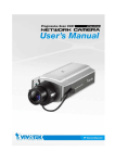
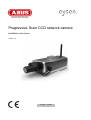
Progressive Scan CCD network camera
Installation instructions
Version 1.2
TV7220 - TV7223
Preface
Dear Customer,
Thank you for purchasing this network camera of the Eyseo series from ABUS Security-Center. You made
the right decision in choosing this state-of-the-art technology,
which complies with the current standards of domestic and European regulations. The CE has been proven
and all related certifications are available from the manufacturer upon request.
To maintain this status and to guarantee safe operation, it is your obligation to observe these operating
instructions! In the event of questions, please contact your local specialist dealer.
This network camera is used for object surveillance. The recorded video signals are transmitted to a
computer digitally via the connected network. The computer software permits simultaneous recording of up
to 16 connected video signals. Data storage is subject to local national data-protection guidelines. Via the
Internet Explorer, you have worldwide access to installed cameras (password-protected).
Precautions
The network camera and connected components must be kept free of moisture (cellars and similar
surroundings are to be strictly avoided). Use of this product for other than the described purpose may lead to
damage of the product. Other hazards such as short-circuiting, fire, electric shock, etc., are also possible.
The equipment is designed for operation using a Class 2 12V DC transformer. No part of the product may be
changed or modified in any way. Connection to the public power network is subject to country-specific
regulations. Please be aware of applicable regulations in advance.
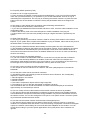
Please observe the following regulations to
ensure trouble-free operation of your
device.
To avoid fire and injury, please observe the
following:
Securely fasten the device at a dry location in
the building.
Ensure sufficient air circulation.
Do not expose the device to temperatures less
than 0°C or more than 35°C.
The device is designed for indoor use only.
Humidity must not exceed 90% (noncondensed).
Ensure that the voltage is disconnected when
performing work on the device.
The network camera is supplied by a 12V DC
transformer.
The transformer should be connected to the
230V AC building mains by means of a
separate, electrically protected line.
Connection work to the building mains is
subject to country-specific regulations
General:
Improper or careless installation work may lead to faults and poor image quality. Therefore please read the
instructions very carefully and follow the installation instructions for lines and components precisely.
The manufacturer reserves the right to make technical modifications at any time.
2
Before using this product
The use of surveillance equipment may be forbidden by law in some countries. This network camera is
not only high-quality web camera but can also be used as part of a flexible surveillance system. Before
using this equipment, make sure that all your surveillance activities are completely legal.
Before installation, check the product for completeness (page 5: Scope of delivery). Read the
installation instructions before installing the network camera. Read the “Hardware installation” chapter
carefully and follow the instructions contained in it to avoid damage caused by faulty assembly or
incorrect installation. This will ensure that the equipment goes into operation correctly for the intended
purpose.
Appendixes A and B contain possible solutions to problems occurring during installation and
configuration.
The installation instructions describe different usage scenarios of the network camera.
Sections marked with
contain special hints and advice for the user. Ignoring this advice can
result in damage to the equipment or injury.
3
Contents
Preface .....................................................................................................................................................2
Precautions ...............................................................................................................................................2
Before using this product ..........................................................................................................................3
Contents ...................................................................................................................................................4
Scope of delivery ......................................................................................................................................5
Hardware installation ................................................................................................................................6
Consult your dealer for the correct installation of peripheral devices.......................................................6
External connections .................................................................................................................. 7
Connections at the rear side ............................................................................................ 7
I/O-connector .................................................................................................................... 7
First access to network camera ................................................................................................................8
Access to the network camera via the Internet Explorer ..........................................................................9
Defining a password to prevent unauthorised access ..............................................................................9
Changing the administrator password ...................................................................................... 10
Installing the plug-in .................................................................................................................. 11
Basic user functions ...............................................................................................................................12
Main window and camera view ................................................................................................. 12
Digital Zoom and Snapshot ...................................................................................................... 13
Client Settings ........................................................................................................................... 14
Administrator settings .............................................................................................................................16
Configuration / video and audio ................................................................................................ 16
Protecting the network camera with a password ...................................................................... 17
Setting up a surveillance application ........................................................................................ 18
Updating the software version .................................................................................................. 18
System configuration ..............................................................................................................................19
System ...................................................................................................................................... 20
Security ..................................................................................................................................... 20
Network ..................................................................................................................................... 21
WLAN configuration .................................................................................................................. 24
Enable the DDNS function ........................................................................................................ 26
Access list ................................................................................................................................. 27
Video and audio ........................................................................................................................ 28
Privacy Mask .................................................................................................................................. 29
Motion sensor ........................................................................................................................... 31
Application ................................................................................................................................ 32
Media .............................................................................................................................................. 32
Server ............................................................................................................................................. 33
Event .............................................................................................................................................. 34
Viewing parameters .................................................................................................................. 36
Maintenance ............................................................................................................................. 36
Appendix .................................................................................................................................................37
A. Troubleshooting.................................................................................................................... 37
B. Frequently asked questions (FAQ) ...................................................................................... 38
C. URL-Commands .................................................................................................................. 40
D. Technical data ...................................................................................................................... 73
E. Licence information .............................................................................................................. 74
4
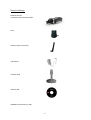
Scope of delivery
Network camera
TV7220/TV7221/TV7222/TV7223
Lens
Antenna (only TV7221/23)
Transformer
Camera stand
Software CD
Installation instructions (on CD)
5
Hardware installation
Make sure that all accessories and articles
listed above are present in the scope of
delivery. Depending on application, an Ethernet
cable may be required. This Ethernet cable
must meet the specifications of UTP Category
5 (CAT 5) and must not be longer than 100
meters.
To prevent the risk of electric shock, first connect the socket of the transformer to the network
camera before inserting the transformer into the mains socket.
Consult your dealer for the correct installation of peripheral devices.
Installation in Ethernet
The Progressive Scan Network camera tries to connect first to the wired Ethernet. If no Ethernet is
available, then it will try to detect the wireless network using the set value.
After power up the camera, the LED at the front will flash red once, then the start-up procedure will
begin. During assignment of the IP address this LED will turn green continuously. After this procedure
was performed successfully, the LED will flash 1/second in green mode.
Installation in the WLAN
If the camera is supplied with electricity and no Ethernet is available, the camera switches to WLAN
mode and searches for an access point with the name “default”. This name is known as the SSID
(Service Set Identifier). If an access point with the SSID “default” is found, the LED on the front lights
blue.
If connection with the basic settings (SSID: default) is not successful, connect the camera via a cable
to the wired network and configure it.
6
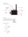
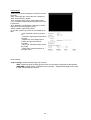
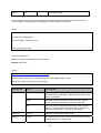
External connections
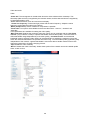
Connections at the rear side
Audio output
Switch: internal /
external
Microphone
Antenna
12VDC
Audio input
Ethernet
connector
I/O-Port
Reset
button
I/O-connector
1 : not used
2 : not used
3 : not used
4 : not used
5 : Ground
6 : Digital input
7 : Digital output
8 : Power 12VDC
Switching input and output
7
First access to network camera
The first access to the network camera should be done by using the Installation Wizard 2.
After the startup of this tool the wizard will search for any connected Eyseo network camera or
videoserver.
The Standard IP address of the videoserver is 169.254.0.99.
If there is a DHCP server running on the network then the IP address assignment will be done
automatically, regarding your network stucture.
The network adapter parameters of thenetwork camera like IP address or subnet mask you can
directly change under [Home / Configuration / Network], and so you can adapt the videoserver
to your network (e.g. IP=192.168.0.99 / subnet mask = 255.255.255.0).
To connect to the network camera just double click the list entry on the result list.
After the start of the Installation wizard 2 the tool might add a virtual IP address to the current
network settings of the PC. It depends whether DHCP in your network is activated or not.
After shut down of the Installation wizard 2 this virtual IP address will be removed.
Using this virtual IP address the first access and configuration process will be much easier. A
manual configuration of the network adapter of the PC is therefore not necessary.
8
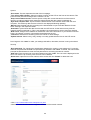
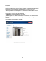
Access to the network camera via the Internet Explorer
Defining a password to prevent unauthorised access
When delivered, no administrator password is defined for the network camera.
The network camera asks for this number at the start of operation. For security reasons, the
administrator should define a new password immediately. After the new administrator password is
stored, the network camera asks for the user name and password every time it is accessed. The
administrator can define up to twenty (20) user accounts. Every user has access to the network
camera, but not to the system configuration. Some system-critical functions are reserved for the
administrator, such as system configuration, user administration and upgrading software programs.
The administrator’s user name is always root and cannot be changed. Following a password change,
the browser displays an authentication window and asks for the new password. After changing the
password, you cannot restore the original administrator password. Your only option is to reset all
default factory settings/parameters.
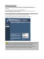
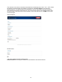
To enter a password:
Open the Internet Explorer and enter the IP address of the camera (e.g.: <http://192.168.0.99>).
You are prompted for authentication:
Î You are now connected with the network camera and can see a video stream.
Note: It may happen that your PC’s security settings prevent a video stream. You can
change the security settings to a lower level under “Tools/Internet Options/Security”. Make sure
you enable Active X Control Elements and Downloads.
9
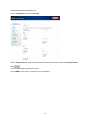
Changing the administrator password
Click “Configuration” and then “Security”.
Under “Root password”, enter the administrator password and confirm it under Confirm password.
Click
.
The new administrator password is saved.
Click “HOME” in the column on the left to exit configuration.
10
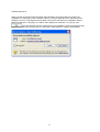
Installing the plug-in
When you first access the network camera under Windows, the web browser may ask for the
installation of a new plug-in for the network camera. This query depends on the Internet security
settings of your PC. If the highest security level is set, the PC will refuse any installation and any
attempt at execution. This plug-in is used for video display in the browser. To continue, click
. If the web browser prevents continuation of the installation, open the Internet security
settings and reduce the security level or consult the IT administrator or network administrator.
11
Basic user functions
Main window and camera view
The view of the main page consists of two parts:
Configuration: You can configure the camera with these steps.
Camera view: Camera video stream
Click the configuration link on the left of the picture to open the configuration page.
Language: Selection for the GUI language of the camera.
Digital output: Here the external digital output can be switched manually.
Local Recording
: Recording to local PC harddrive can be started and stopped. The record path can
be set under „Client settings/MP4 Record“.
12
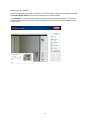
Digital Zoom and Snapshot
Click the magnifying glass under camera view. The control field for digital zooming appears. Disable
the Disable Digital Zoom box and change the zoom factor with the slider.
Click “Snapshot”. The web browser displays a new window containing the snapshot. To save the
snapshot, either left-click it and then click the diskette icon or right-click it and select Save from the
context menu.
13
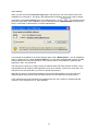
Client Settings
When you first access the Connection Type page under Windows, the web browser asks for the
installation of a new plug-in. This plug-in was registered at certification and can be used to change
parameters on the Client settings page. To install the plug-in, click
. If the web browser
prevents continuation of the installation, open the Internet security settings and reduce the security
level or consult the IT administrator or network administrator.
Two settings are available on the Client-Settings page. Under “Media Options”, you can disable the
audio- or video function. Under “Protocol Options”, you can select a transmission protocol for data
transfer between the client and the server. Two protocol options are available for optimising the
application: UDP, TCP and HTTP.
The UDP protocol gives you a larger number of realtime audio and video streams. However, some
data packets can be lost due to the large data volume in the network. Pictures can be unclear. The
UDP protocol is recommended if you have no special requirements.
With the TCP protocol, fewer data packets are lost and the video display is more accurate. The
disadvantage of this protocol is that the realtime stream is worse than with the UDP protocol.
HTTP mode will use the HTTP Mode only (standard port 80), this is useful for firewall protected
networks. In this mode there is no audio available.
14
The selection of the client is normally recommended in the following order: UDP – TCP – HTTP. When
the network camera has been successfully connected, the “Protocol Options” box shows the
selected protocol. The selected protocol is registered in your PC and used for the next connection.
After changing the network environment or if you want to search again for the network camera using
the web browser, select the UDP protocol manually, save it and then return to “HOME” to set up the
connection again.
Internet Explorer:
Mozilla Firefox:
<url> http://<Network Camera>/clientset.html
Network Camera is the original IP address or the hostname of the network camera.
15
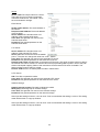
Administrator settings
Configuration / video and audio
Best performance is produced by the maximum frame rate with best video quality and minimum
network bandwidth. The three factors “Max frame rate”, “Constant bit rate” and “Fixed quality” on the
video configuration page are interrelated.
Mobile access to the network camera
Many modern mobile telephones support access to MPEG4 videostream and GSM-AMR audio data.
Due to restricted bandwidth, only a maximum resolution of 176x144 pixels is supported.
For high frame rates
To obtain a good visual realtime effect (more than 20 frames/s), the network bandwidth must be
sufficiently large. If the network bandwidth is higher than 1 Mbps, the value for the “Constant bit rate”
must be set to 1000Kbps or 1200Kbps and the “Fixed quality” to the highest quality. In the PAL
system, the maximum frame rate is 25, and in the NTSC system, 30 frames per second. If your
network bandwidth is more than 384Kbps, you can fix the bit rate according to your bandwidth and the
maximum frame rate to 25 or 30 fps (frames per second). If the pictures in your environment are
changed drastically, you can reduce the maximum frame rate to 20 frames per second to set the data
transmission rate lower. This gives you a better video quality, and the human eye cannot distinguish
between 20, 25 and 30 frames per second. If the network bandwidth is less than 384 Kbps, adjust the
“Constant bit rate” according to the bandwidth and try to get the best performance by fine-tuning the
“Max frame rate”. In a “slow” network, a high frame rate results in unclear, distorted images. Another
way to improve quality is to select “176x144” in the “Size” option, or “320x240” for a larger view of the
pictures. Video quality also depends on the number of users in the network. Performance can also be
affected by a bad connection and by a restriction of the network burst.
16
For higher-quality pictures
For best video quality, set “Fixed quality” to “Detailled” or “Excellent” and the “Max frame rate” so that
it corresponds to the bandwidth of your network. If your network is slow and you get “broken” images,
go to the TCP protocol under Connection Type and select a more suitable transmission mode.
Pictures can also be affected by a time delay due to a slower connection. The more users in the
network, the greater this time delay.
For high frame rates with high-quality pictures
If you have a broadband network, set “Constant bit rate” to or higher and leave “Constant bit rate”
unchanged. You can also set the bandwidth according to the actual network speed or the frame rate.
Start with 30 frames per second and reduce this setting until you get the best performance. However,
do not reduce it to less than 15 frames per second. If the picture quality is not improved, select a lower
setting for “Constant bit rate”.
Protecting the network camera with a password
Root password
The network camera is supplied with no password defined. Using this password, all users have access
to the network camera, including its configuration, as long as they know the IP address. If other users
are to have access to the network camera, you should therefore assign a password to the camera. To
activate protection, enter a new password. The administrator is identified with this password.
17
Opening accounts for new users
Under “Configuration”, select “Security”. Now go to the “Add user” section.
Add an account with user name and password for a second user. You can define up to twenty
accounts for other users of the network camera. The camera checks only the access permission of the
corresponding user name and password. This means that two or more users can use the same
account at different levels.
Setting up a surveillance application
The administrator can use the built-in motion sensor for monitoring and signalling changes to the
picture. Snapshots of events can be sent to an e-mail address or to an FTP server. For this purpose,
settings have to be made under the configuration points “Network”, “Motion sensor” and “Application”.
For detailed information, see “System configuration”.
Updating the software version
You can download the latest software from the website www.abus-sc.com. A user-friendly update
wizard is provided for updating the network camera software (Installation Wizard / Upgrade). Only the
administrator can start the update function. To update the system:
1. Download the firmware file with the name xxx.pkg from the corresponding products folder.
2. Start the update wizard and follow the instructions.
3. The complete procedure finishes in a few minutes, and the system is automatically rebooted.
You can also update the software via the menu item Configuration / management of the network
camera.
If there is a power failure during the write process of the flash memory, the program in the
memory of the CMOS-network camera may be irreparably damaged. If the security network
camera cannot be correctly restarted following the update, consult your dealer’s technical support.
18
System configuration
Only the administrator has access to system configuration. The following sections explain each
element in the left column. Specific tasks on the Options page are printed bold. The administrator can
enter the URL under the picture to jump direct to the pictures page of the configuration.
<URL>http://”Network Camera”/setup/config.html
<Network Camera> is the domain name or original IP address of the network camera.
<URL>http://”Network Camera”/setup/system.html
<Network Camera> is the domain name or original IP address of the network camera.
19
System
„Host name“ The text represents the title of the homepage.
„Turn off the LED indicator“ Select this option to switch off the LED on the front of the camera. This
prevents other persons knowing that the camera is in use.
„Keep current date and time“ Click this option to keep the current date and time of the network
camera. An internal realtime clock stores the date and time after the system is switched off.
„Sync with computer time“ Synchronises the date and time of the network camera with the local
computer. The read-only date and time of the PC are displayed following updating.
„Manual“ Sets the date and time according to the administrator’s input. Note the date/time format
when entering in the respective fields.
„Automatic“ Synchronises the date and time with the NTP server via the Internet every time the
network camera is switched on. This is not possible if the respective time server cannot be reached.
„NTP server“ Assigns the IP address or the domain name of the time server. If you leave this text box
empty, the network camera is connected to the default time servers.
„Time zone“ Sets the time according to the time server for local settings.
“Update interval” Select hourly, daily, weekly or monthly update with the time on the NTP server.
Don’t forget to click “Save” to make your settings take effect; otherwise, the time is not synchronised.
Security
„Root password“ For changing the administrator password by entering a new password. For security
reasons, the passwords entered are represented by asterisks. After “Save” is clicked, the web browser
prompts the administrator to enter the new password for accessing the network camera.
„Add user“ Enter the new user name and password and click “Add”. The new user is displayed on the
list of user names. Up to twenty user accounts can be defined.
„Delete user“ Open the list of user names, select a user and click “Delete” to delete this user.
<URL> http://<Netzwerkkamera>/setup/security.html
<Network > is the domain name or original IP address of the network camera.
20
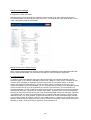
Network
All changes made on this page cause a system reboot so that they can take effect. Make sure that the
fields are correctly filled before you click “Save”.
Network connection
“LAN” The default is LAN. Use this setting if the camera is connected to a LAN. You also have to
make other settings such as the IP address or the subnet mask.
“PPPoE” Use this setting if the camera is connected directly to a DSL modem. You will receive a user
name and password from your ISP (Internet Service Provider).
“Get IP address automatically” At every restart of the network camera, an IP address is assigned.
“Use fixed IP address” The network data such as the IP address is defined here.
“IP address” This is needed for network identification.
“Subnet mask” Defines whether the destination is in the same subnet. The default value is
“255.255.255.0”.
“Default router” Gateway for transmitting pictures to another subnet. An invalid router setting
prevents transmission to these destinations in different subnets. For a Cross link connection from the
camera to the PC you have to type in an IP address in the same subnet (e.g. 192.168.0.1)
“Primary DNS” Server of the primary domain name with which the hostnames are converted into IP
addresses.
“Secondary DNS” Server of the secondary domain name for generating a reserve copy of the
primary DNS.
“Enable UPnP presentation” This enables Universal Plug and Play. This is an extension of the PnP
standard to network environments.
“Enable UPnP port forwarding” This enables Universal Plug and Play port forwarding for network
services.
“PPPoE” If using the PPPoE interface, fill in the following settings from ISP: user name, password,
password confirmation
HTTP:
“HTTP port” This port can be different from the standard port 80 (80; or 1025 to 65535). If this port is
changed, users must be informed to ensure a successful connection. Example: If the administrator
changes the HTTP port of the network camera with the IP address 192.168.0.99 from 80 to 8080,
users have to enter “http://192.168.0.99:8080” in the web browser instead of “http://192.168.0.99”.
“Secundary HTTP Port” HTTP Port for stream 2
“Access name for stream 1” Access name for the MJPEG stream 1
“Access name for stream 2” Access name for the MJPEG stream 1
FTP:
„FTP-Port“ This is the internal FTP server port. This can be another than port 21 (21, or 1025 to
65535).
21
RTSP streaming:
“RTSP-Authentication” Enable the authentication of RTSP. On connection to an RTSP client
username and password will be checked.
Note: This function must be supported by the media player (e.g. Realplayer 10.5)
“Access name for stream 1” The access name for establishing a connection from a client. The
codec type must be MPEG 4! Use rtsp://<IP address>:RTSP-port/<access name 1> to establish a
connection.
“Access name for stream 2” The access name for establishing a connection from a client. The
codec type must be MPEG 4! Use rtsp://<IP address>:RTSP-port/<access name 2> to establish a
connection.
“RTSP port” This port can differ from the default Port 554 (554, or 1025 to 65535). If you change it,
note that the input format is analogue to the HTTP port.
“RTP Port for video” This can be other than the default port 5558. It must be an even number.
“RTCP port for video” This port must be RTP port for video plus 1.
“RTP port for audio” This can be other than the default port 5556. It must be an even number.
“RTCP port for audio” This port must be RTP port for audio plus 1.
Multicast: The settings can be configured for stream one and two.
“Always multicast” This option turns on the multicast, bandwidth-conserving technology.
“Multicast group address” It specifies an arbitrary group of IP hosts that have joined the group and
want to receive traffic sent to this group.
“Multicast video port” This can be other than the default port 5560. It must be an even number.
“Multicast RTCP video port” This port must be multicast video port plus 1.
“Multicast audio port” This can be other than the default port 5562. It must be an even number.
“Multicast RTCP audio port” This port must be multicast audio port plus 1.
“Multicast TTL” Time to Live
Pay attention to the port forwardings in your Router. All ports like http, rtsp must be forwarded.
22
<URL> http://<Network Camera>/setup/network.html
<Network Camera> is the domain name or original IP address of the network camera.
23
WLAN configuration
“SSID” (Service Set Identifier) The name that identifies the wireless network. The access point and
the WLANnetwork camera must use the name SSID. The factory setting is “default”. IMPORTANT:
The max. length is 32 characters; do not use: “ , ”, <, > and spaces.
“Wireless mode” Select one of the following:
“Infrastructure” Thenetwork camera is connected to the network via an access point.
“Ad-Hoc” In this mode, thenetwork camera can communicate direct with another network
adapter (network card). A so-called Peer-to-Peer environment is set up.
“Channel” In infrastructure mode, the channel used is selected automatically by the camera. In AdHoc mode, the channel must be set manually according to the other network adapter.
“TX rate” Set the maximum transmission speed in the network. In the factory, the speed is set to
select automatically (“auto”), and the camera always tries to reach the highest transmission speed
according to the environment.
“Preamble” A so-called preamble is set before each data packet. This preamble is used to
synchronise the receiver and the sender. With a “short preamble”, the synchronisation length is shorter
and therefore not so secure.
“Security” Select the encryption method:
“None” No encryption selected.
“WEP” (Wired Equivalent Privacy) A 64- or 128-bit key is used for encryption (HEX or ASCII).
For communication with other equipment, these keys must be the same on both devices.
“WPA-PSK/WPA2-PSK” (Wi-fi Protected Access – Pre Shared Keys) With this method,
dynamic keys are used. As encryption protocols, TKIP (Temporal Key Integrity Protocol) or
AES (Advanced Encryption Standard) can be selected. A so-called Pre-Shared Key must be
defined.
“Auth mode” Authentication mode: Select one of the following methods:
“Shared” This mode permits communication only with equipment using the same WEP key.
“Open” The key is communicated over the whole network.
“Key length” Select 64 or 128 bit.
“Key format” Key format
“HEX” Hexadecimal format
“ASCII” ASCII format
“Network key” For different key formats, different key lengths are expected.
64 Bit: 10 hex digits or 5 characters
128 Bit: 26 hex digits or 13 characters
IMPORTANT: If you want to use characters 22 ("), 3C (<) or 3E (>), you cannot use ASCII
format.
“Pre-Shared-Key” Enter this key in ASCII format with a length of 8 ~ 63 characters.
Incorrect settings may prevent access to the camera. If the system can no longer be
addressed, read the notes on restoring the factory settings in the appendix.
24
<URL> http://<Network Camera>/setup/wireless.html
<Network Camera> is the domain name or original IP address of the network camera.
25
Enable the DDNS function
„Provider“ The provider list contains four hosts that provide DDNS services. Connect to the serviceprovider’s website to make sure that the service is available.
„Host name“ This field must be completed if you want to use the DDNS service. Enter the hostname
registered with the DDNS server.
„Username/Email“ The user name and the e-mail address must be entered in this field to set up a
connection to the DDNS server or to inform users about the new IP address. Important: If you enter a
user name in this field, you must enter a password in the next field.
„Password/Key“ To be able to use the DDNS service, enter the password or the key.
<URL> http://<Netzwerkkamera>/setup/ddns.html
<Network Camera> is the domain name or original IP address of the network camera.
26
Access list
“Allow list” The IP list of accepted IPs is entered here and added to the access list. As a factory
default, all IPs are accepted. If necessary, delete the entire list.
“Start IP address” Enter the first address of the desired range.
“End IP address” Enter the last address of the desired range.
“Delete allow list” Delete desired ranges from the access list.
“Deny list” Define the IP lists to be blocked.
“Delete deny list” Delete blocked IP lists.
<URL> http://<Network Camera>/setup/accesslist.html
<Network Camera> is the domain name or original IP address of the network camera.
27
Video and audio
Video
“Video title” The text appears in the black bar above the video window with a timestamp. This
timestamp (date and time) is supplied by the network camera, and the date and time are supplied by
an integrated realtime clock.
“Color” Selects between colour and monochrome display.
“Power line frequency” Fluorescent light pulses with the mains frequency. Adapt the mains
frequency to eliminate this pulsing in the picture.
„Mode (Compression)“ JPEG or MPEG-4 compression is possible
“Frame size” Four options are available for the three video sizes: “176x144”, “320x240” and
“640x480”.
Three parameters are available for setting the video quality.
“Max frame rate” Restricts the maximum frame rate, which can be combined with the “Key frame
interval” (only in MPEG-4 mode) to optimise bandwidth use and video quality. If the user wants to
define bandwidth usage independently of the video quality, “Constant bit rate” and the desired
bandwidth must be selected. Video quality can be affected due to sending the maximum frame rate
within the restricted bandwidth if the pictures are fast-moving. To ensure video quality (quantising rate)
independent of the network, a greater bandwidth is used to be able to handle maximum frame rate
during the transmission of rapidly changing pictures.
“Flip” Rotates the video vertically.
“Mirror” Rotates the video horizontally. Select these options if the network camera is installed upside
down or back to front.
28
Picture settings
Click “Image settings” to open another
window in which you can set the
“Brightness”, “Contrast”, “Saturation”
and the “Sharpness” of the video picture.
To check your settings, click “Preview”.
To save the picture parameters, click “Save”.
To discard your changes, click “Restore”.
“White balance” Set the value for an
optimal colour hue.
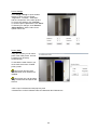
Privacy Mask
Using this function you can mask
parts of the video picture. At most
5 windows can be setup
simultaneously.
To activate the mask function you
must check the function “Enable
privacy mask”.
This function should not be
activated when PTZ cameras are
installed.
This function only can be setup
using the MS Internet Explorer with
ActiveX.
<URL> http://<Videoserver>/setup/privacy.html
<Videoserver> ist die IP-Adresse oder der Hostname des Videoservers.
29
CCD settings
„IRIS level“ Controls the aperture of the auto iris lens
manually
„AGC“ Automatic gain control: Normal or Maximum
“AES” Auto Electronic Shutter
“ALC” Automatic light control, fixed shutter speed
“Low Lux Mode” extends the shutter speed in low lux
environment
„BLC“ Backlight compensation: It will help to identify
objects in front of strong light sources.
„Swich to B/W in night mode“ option
„IR cut filter“ Options to control the removable IR cut
filter:
- Auto: Automatic switching under 2
lux
- Schedule: Switching will follow fixed
set times
- Digital input: If the digital input is
closed, the night mode will be
activated.
- Day mode: manual activation of the
day mode
- Night mode: manual activation of
the night mode
Audio settings
“Audio settings” Select the audio type and a bit rate.
“AAC” (Advanced Audio Coding) Special codec for audio data compression under MPEG4.
“GSM-AMR” (Global System for Mobile Communications – Adaptive Multi Rate) Voice codec
in GSM mobile telephone network.
30
Motion sensor
“Enable motion detection” Enables motion detection.
“New” Adds a new window. A maximum of three windows can be open simultaneously. To resize the
window or move the title bar, click the window frame, keep the mouse button pressed and drag the
window to the required size. Close the window by clicking the “x” in the top right corner.
“Save” Click this button to save window settings. A bar graph rises or falls according to the picture
variation. A green bar means that the picture variation is below the surveillance level, while a red bar
means that the picture variation is above the surveillance level. If the bar is red, the detected window
appears with a red frame. When you return to the homepage, the monitored window is hidden. As
soon as motion is detected, the red frame is displayed.
“Window name” The text appears at the top of the window.
“Sensitivity” Sensitivity in changes of picture sequence (e.g.: sensitivity high: triggering by slight
picture change).
“Percentage” Detectable object size (low: small objects are detected; high: only large objects are
detected)
This figure shows the screen after you click “Save”.
31
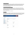
Application
There are 3 sections in application page: Event, Server and Media Settings.
To create an application event the basic order for configuration is: Media -> Server -> Event.
There can be setup at most 3 events, 5 servers and 5 medias.
<URL> http://<Videoserver>/setup/application.html
Media
Media name The unique name for the media.
There are 3 kind of media: Snapshot, video clip and system log.
Snapshot
Source The source of stream: stream 1 or stream 2
Send pre-event images The number of pre-event images.
Send post-event images The number of post-event images.
File name prefix The prefix name will be added to the file name of the snapshot images.
Video clip
Source The source of the stream: stream 1 or stream 2
Pre-event recording The interval of pre-event recording
in seconds
There are 2 limitations for the video clip file.
Maximum duration The maximum recording file
duration in seconds
Maximum file size The maximum file size that would be
generated
File name prefix The prefix name will be added to the
file name of the video file.
System log
Will send the current status log file.
32
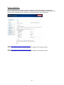
Server
Server name The unique name for a server.
There are four kind of servers supported.
Those are email server, FTP server, HTTP
server and network storage.
Email Server
Sender email address The email address of
the sender
Recipient email address The email address
of the recipient
Server address The domain name or IP
address of the external email server.
User name This granted user name on the
external email server.
Password This granted password on the
external email server.
FTP Server
Server address The domain name or IP
address of the external FTP server.
Server port This can be other than the default
port 21. The user can change this value from 1025 – 65535.
User name This granted user name on the external FTP server.
Password This granted password on the external FTP server.
Remote folder name Granted folder on the external FTP server. The string must be conform to that of
the external FTP server. Some FTP servers cannot accept preceding slash symbol in front of the path
without virtual path mapping. Refer to the instructions for the external FTP server for details. The
folder privilege must be open for upload
Passive mode Check it to enable passive mode in transmission.
HTTP Server
URL The URL to upload the media.
User name This granted user name on the external HTTP server.
Password This granted password on the external HTTP server.
Network Storage
Network storage location The path to upload the media.
Workgroup The workgroup for network storage.
User name This granted user name on the network storage.
Password This granted password on the network storage.
After input the settings of server, user can click “Test” to test whether the setting is correct. The testing
result will be shown in a pop-up window.
After input the settings of server, user can click “Test” to test whether the setting is correct. The testing
result will be shown in a pop-up window.
33
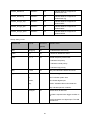
Event
Event name The unique name for an event.
Enable this event Check it to enable this event.
Priority The event with higher priority will be executed first.
Delay second(s) before detecting next event The delay to check next event. It is used in motion
detection and digital input trigger type.
The videoserver supports 3 different trigger types:
Video motion detection Select the windows which need to be monitored.
Periodic The event is triggered in specific intervals. The unit of trigger interval is minute.
System boot The event is triggered when the system boot up.
Event schedule
Sun ~ Sat Select the days of the week to perform the event.
Time show Always or input the time interval.
Action
Server name Check it to send the selected media when event was triggered.
34
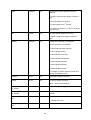
Recording
The network camera supports recording on network storage. The operation of editing recording item is
the same as the one in the application page. User can define the recording name, status, weekly and
time schedule, stream source and destination of recording. There can be at most 2 recording entries.
To do recording on network storage, please add network storage server in application page first.
Recording entry name The unique name for the recording entry.
Enable this recording Check it to enable this event.
Priority The recording with higher priority will be executed first.
Source The source of the stream: stream 1 or stream 2.
Schedule
Sun ~ Sat Select the days of the week to perform the event.
Time shows “Always” or input the time interval.
Destination Network storage server from application page.
Total cycle recording size The total size for cycle recording in Kbytes.
Size of each file for recording The single file size in Kbytes.
File name prefix The prefix name will be added on the file name of the recording.
<URL> http://<network camera>/setup/recording.html
When click on destination, a page appears listing all *.mp4 files in this destination.
User can select some files to delete or delete all files.
35
Viewing the log file
Click this link on the configuration page to display the system log file. The contents of the file supply
useful information about the configuration and the connection following a system start. The standard of
the log file is RFC 3164. You can also send data to a log server. Enable “Remote Protocol” and enter
the IP address and the port number of the server.
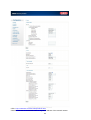
Viewing parameters
Click this link on the configuration page to display all system parameter sets. The contents correspond
to those of CONFIG.INI.
Maintenance
Reboot system
Click to reboot the system.
Factory default
Click to restore the factory settings. All previous settings are discarded.
Upgrade firmware
Like an update with the installation wizard, you can update the firmware of the network camera here.
You can download the latest firmware from www.abus-sc.com. Select the update file (flash.bin) and
click “Upgrade”. The update takes a short time. When you restart the camera, it is started with the new
firmware.
36
Appendix
A. Troubleshooting
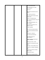
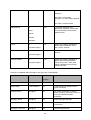
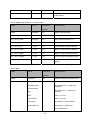
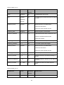
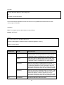
Status LEDs
Condition / LED Color
System start
During boot up
Network search/setup
Network ok
During Firmware Upgrade
Green
On
Off
On
1/s
1/s
Red
1/s (once)
1/s
Off
On
0.1/s
Resetting and restoring
At the back side of the netzwork camera is a button. Press this button to reset the system or restore
the factory parameter settings. Sometimes the normal system status can be restored by a reset. If you
have further problems following a reset, restore the factory parameter settings and reinstall and
reconfigure the system.
If the factory parameter settings are restored, all
the previous settings are deleted. The system can be
reset or restored.
Reset button
RESET:
Press the reset button with a pointed object.
RESTORE:
1. Press the button continuously with a pointed object.
2. Wait until the LEDs blink fast.
3. Release the reset button.
37
B. Frequently asked questions (FAQ)
Q. What do I do if I forget my password?
A. Every access to the network camera requires an authentication. If you are one of the managing
users, ask your administrator for your password. If you are the administrator, there is no way of
reactivating the root password. The only way of accessing the network camera is to press the reset
button on the rear of the camera to restore the factory-set parameters and then reconfigure the
system.
Q. Why does no video appear from the network camera following authentication?
A. This problem can be caused by various factors:
1. If you have just installed the network camera and see no video, check the video modulation on the
configuration page.
2. Reduce the security level of the Internet Explorer to enable installation of the plug-ins.
3. If this problem recurs, the users are possibly working at a higher level than is permitted by the
system.
Q. What is the plug-in for?
A. The plug-in provided by the network camera is used for showing video streams in the Internet
Explorer. If your system does not permit the installation of plug-in software, reduce the security level of
the web browser. Consult your network administrator.
Q. Why is there a difference between the timestamp and the system time of the PC/notebook?
A. The timestamp is based on the system time of the network camera. This is supplied by an internal
realtime clock and can automatically be synchronised with a time server if the network camera is
connected to the Internet and the function is enabled. Differences of an hour or more are caused by
the time zone setting.
Q. Why is the picture not refreshed regularly?
A. If you use a modem, the bandwidth of the PPP connection is much less that with an Ethernet
connection. If the timestamp difference is unstable, reduce the UART FIFO for reception and
transmission under Modem Properties in the Control Panel. If you use the Ethernet, the reason may
be the length of time required to store snapshots in memory after an event occurs.
Q. How many users can watch the video simultaneously?
A. The number of users is restricted to 20. However, the video quality depends on the network
bandwidth.
Q. How fast is the video rate of the network cameras?
A. The MPEG4 Codec can internally process 30 frames a second. However, the overall quality
depends on various coefficients.
1. Data throughput in the network
2. Shared bandwidth
3. Number of users
4. The visible “complicated” objects result in large image files.
5. The settings on your PC that are responsible for displaying pictures.
The transmission rate of a normal local network can reach over 200 kilobytes per second and
approximately 10 to 20 frames per second.
Q. How can I keep access to video streams of the network camera as secure as possible?
A. The network camera was developed for surveillance purposes and has many flexible interfaces.
User authentication and special confirmation during installation can prevent unauthorised access to
the network camera. You can also change the HTTP port to a non-public number. Check the system
log for abnormal activities and their causes.
Q. How fast can the network camera check the state of the digital inputs?
A. The network camera checks the input state in less than half a second. However, to avoid the
conditions of a repeated check and ensure a correct functioning of equipment connected to the digital
outputs, the network camera delays for 3 seconds after each adaptation of the condition. You can
modify this according to your own specific applications. During this period, other conditions are
ignored.
38
Q. Why is access to the network camera not possible while I am setting options in the application?
A. If the network cameras are started by events, snapshots need more time since they are written to
memory. If the events occur too often, the system is constantly trying to store the pictures. If an event
occurs very frequently, use sequential mode or an external recording program to record the pictures. If
you want to access the pictures via FTP, the parameter can be set lower since FTP responds faster
than the web. If the system is busy with configuration, press the reset button to restore the factory
settings and store the system.
Q. The camera was correctly configured, but access to the camera via the http protocol or the RTSP
protocol is denied.
A. Make sure that the corresponding ports (default: Port 80 or 554) in any routers used or the firewall
are released (shared). Test the network protocol “Ping” (Windows command line input: ping <IP
address>).
Q. The network camera is connected to the network via a router, but access to the camera is denied.
A. If you want to connect the camera via a router (gateway), you have to define the gateway IP
(standard router). You can only do this if you first connect the camera direct via a cross-link cable and
then configure it.
Q. The network camera is located behind a router with a local IP. How can I access this camera from
the Internet?
A. The router receives a public IP, accessible to anyone, when you dial via the modem (e.g. DSL).
Forwarding – e.g., of an http query from the Internet – is directed first to this public IP. The router must
now be configured so that this query is forwarded to the local IP. Look up the following terms in your
router manual: NAT (Network Address Translation, IP forwarding, IP Server).
39
C. URL-Commands
Style convention
In URL syntax and in descriptions of CGI parameters, a text within angle brackets denotes a content
that is to be replaced with either a value or a string. When replacing the text string also the angle
brackets shall be replaced. An example of this is the description of the name for the server, denoted
with <servername> in the URL syntax description below, that is replaced with the string myserver in
the URL syntax example, also below.
URL syntax' are written with the “Syntax:" word written in bold face followed by a box with the referred
syntax as seen below. The name of the server is written as <servername>. This is intended to be
replaced with the name of the actual server. This can either be a name, e.g., "mywebcam" or
"thecam.adomain.net" or the associated IP number for the server, e.g., 192.168.0.220.
Special note will be marked as RED words to take care.
Syntax:
http://<servername>/cgi-bin/viewer/video.jpg
Description of returned data is written with "Return:" in bold face followed by the returned data in a
box. All data returned as HTTP formatted, i.e., starting with the string HTTP is line separated with a
Carriage Return and Line Feed (CRLF) printed as \r\n.
Return:
HTTP/1.0 <HTTP code> <HTTP text>\r\n
URL syntax examples are written with "Example:" in bold face followed by a short description and a
light grey box with the example.
Example: request a single snapshot image
http://mywebserver/cgi-bin/viewer/video.jpg
General CGI URL syntax and parameters
CGI parameters are written in lower-case and as one word without any underscores or other
separators. When the CGI request includes internal camera parameters, the internal parameters must
be written exactly as they are named in the camera or video server. The CGIs are organized in
function related directories under the cgi-bin directory. The file extension of the CGI is required.
Syntax:
http://<servername>/cgi-bin/<subdir>[/<subdir>...]/<cgi>.<ext>
[?<parameter>=<value>[&<parameter>=<value>...]]
Example: Setting digital output #1 to active
40
http://mywebserver/cgi-bin/dido/setdo.cgi?do1=1
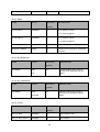
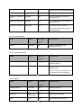
Security level
SECURITY
LEVEL
SUB-DIRECTORY
DESCRIPTION
0
anonymous
Unprotected.
1 [view]
anonymous, viewer,
dido, camctrl
1. Can view, listen, talk to camera
2. Can control dido, ptz of camera
4 [operator]
anonymous, viewer,
dido, camctrl, operator
Operator’s access right can modify most of camera’s
parameters except some privilege and network options
6 [admin]
anonymous, viewer,
dido, camctrl, operator,
admin
Administrator’s access right can fully control the
camera’s operation.
7
N/A
Internal parameters. Unable to be changed by any
external interface.
Get server parameter values
Note: The access right depends on the URL directory.
Method: GET/POST
Syntax:
http://<servername>/cgi-bin/anonymous/getparam.cgi?[<parameter>]
[&<parameter>…]
http://<servername>/cgi-bin/viewer/getparam.cgi?[<parameter>]
[&<parameter>…]
http://<servername>/cgi-bin/operator/getparam.cgi?[<parameter>]
[&<parameter>…]
http://<servername>/cgi-bin/admin/getparam.cgi?[<parameter>]
[&<parameter>…]
where the <parameter> should be <group>[_<name>] or <group>[.<name>] If you do not specify the
41
any parameters, all the parameters on the server will be returned. If you specify only <group>, the
parameters of related group will be returned.
When query parameter values, the current parameter value are returned.
Successful control request returns paramter pairs as follows.
Return:
HTTP/1.0 200 OK\r\n
Content-Type: text/html\r\n
Context-Length: <length>\r\n
\r\n
<parameter pair>
where <parameter pair> is
<parameter>=<value>\r\n
[<parameter pair>]
<length> is the actual length of content.
Example: request IP address and it’s response
Request:
http://192.168.0.123/cgi-bin/admin/getparam.cgi?network_ipaddress
Response:
HTTP/1.0 200 OK\r\n
Content-Type: text/html\r\n
Context-Length: 33\r\n
\r\n
network.ipaddress=192.168.0.123\r\n
Set server parameter values
Note: The access right depends on the URL directory.
Method: GET/POST
42
Syntax:
http://<servername>/cgi-bin/anonymous/setparam.cgi? <parameter>=<value>
[&<parameter>=<value>…][&update=<value>][&return=<return page>]
http://<servername>/cgi-bin/viewer/setparam.cgi? <parameter>=<value>
[&<parameter>=<value>…][&update=<value>] [&return=<return page>]
http://<servername>/cgi-bin/operator/setparam.cgi? <parameter>=<value>
[&<parameter>=<value>…][&update=<value>] [&return=<return page>]
http://<servername>/cgi-bin/admin/setparam.cgi? <parameter>=<value>
[&<parameter>=<value>…][&update=<value>] [&return=<return page>]
PARAMETER
VALUE
DESCRIPTION
<group>_<name>
value to assigned
Assign <value> to the parameter <group>_<name>
update
<boolean>
set to 1 to actually update all fields (no need to use update
parameter in each group)
return
<return page>
Redirect to the page <return page> after the parameter is
assigned. The <return page> can be a full URL path or relative
path according the the current path. If you omit this parameter, it
will redirect to an empty page.
(note: The return page can be a general HTML file(.htm, .html) or
a Vivotek server script executable (.vspx) file. It can not be a CGI
command. It can not have any extra parameters. This parameter
must be put at end of parameter list)
Return:
HTTP/1.0 200 OK\r\n
Content-Type: text/html\r\n
Context-Length: <length>\r\n
\r\n
<parameter pair>
43
where <parameter pair> is
<parameter>=<value>\r\n
[<parameter pair>]
Only the parameters that you set and readable will be returned.
Example: Set the IP address of server to 192.168.0.123
Request:
http://myserver/cgi-bin/admin/setparam.cgi?network_ipaddress=192.168.0.123
Response:
HTTP/1.0 200 OK\r\n
Content-Type: text/html\r\n
Context-Length: 33\r\n
\r\n
network.ipaddress=192.168.0.123\r\n
Available parameters on the server
Valid values:
VALID VALUES
DESCRIPTION
string[<n>]
Text string shorter than ‘n’ characters
password[<n>]
The same as string but display ‘*’ instead
integer
Any number between (-231 – 1) and (231 – 1)
positive integer
Any number between 0 and (232 – 1)
<m> ~ <n>
Any number between ‘m’ and ‘n’
domain name[<n>]
A string limited to contain a domain name shorter than ‘n’ characters (eg.
www.ibm.com)
email address [<n>]
A string limited to contain a email address shorter than ‘n’ characters (eg.
[email protected])
ip address
A string limited to contain an ip address (eg. 192.168.1.1)
mac address
A string limited to contain mac address without hyphen or colon
connected
boolean
A boolean value 1 or 0 represents [Yes or No], [True or False], [Enable or
44
Disable].
<value1>,
Enumeration. Only given values are valid.
<value2>,
<value3>,
…
blank
A blank string
everything inside <>
As description
NOTE: The camera should prevent to restart when parameter changed.
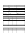
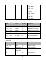
Group: system
NAME
VALUE
SECURITY
DESCRIPTION
(get/set)
hostname
string[40]
1/6
host name of server
ledoff
<boolean>
6/6
turn on(0) or turn off(1) all led
indicators
date
<yyyy/mm/dd>,
6/6
Current date of system. Set to ‘keep’
keeping date unchanged. Set to
‘auto’ to use NTP to synchronize
date.
6/6
Current time of system. Set to ‘keep’
keeping time unchanged. Set to
‘auto’ to use NTP to synchronize
time.
6/6
NTP server
6/6
Indicate timezone and area
keep,
auto
time
<hh:mm:ss>,
keep,
auto
ntp
<domain name>,
<ip address>,
<blank>
timezoneindex
-489 ~ 529
-480: GMT-12:00 Eniwetok,
Kwajalein
-440: GMT-11:00 Midway Island,
Samoa
-400: GMT-10:00 Hawaii
45
-360: GMT-09:00 Alaska
-320: GMT-08:00 Las Vegas,
San_Francisco,
Vancouver
-280: GMT-07:00 Mountain Time,
Denver
-281: GMT-07:00 Arizona
-240: GMT-06:00 Central America,
Central Time,
Mexico City, Saskatchewan
-200: GMT-05:00 Eastern Time, New
York, Toronto
-201: GMT-05:00 Bogota, Lima,
Quito, Indiana
-160: GMT-04:00 Atlantic Time,
Canada, Caracas
,La Paz, Santiago
-140: GMT-03:30 Newfoundland
-120: GMT-03:00 Brasilia, Buenos
Aires,
Georgetown, Greenland
-80: GMT-02:00 Mid-Atlantic
-40: GMT-01:00 Azores,
Cape_Verde_IS.
0: GMT Casablanca, Greenwich
Mean Time:Dublin,
Edinburgh, Lisbon, London
40: GMT 01:00 Amsterdam, Berlin,
Rome,
Stockholm, Vienna, Madrid, Paris
41: GMT 01:00 Warsaw, Budapest,
Bern
80: GMT 02:00 Athens, Helsinki,
Istanbul, Riga
81: GMT 02:00 Cairo
82: GMT 02:00 Lebanon, Minsk
46
83: GMT 02:00 Israel
120: GMT 03:00 Baghdad, Kuwait,
Riyadh,
Moscow, St. Petersburg, Nairobi
121: GMT 03:00 Iraq
140: GMT 03:30 Tehran
160: GMT 04:00 Abu Dhabi, Muscat,
Baku,
Tbilisi, Yerevan
180: GMT 04:30 Kabul
200: GMT 05:00 Ekaterinburg,
Islamabad, Karachi,
Tashkent
220: GMT 05:30 Calcutta, Chennai,
Mumbai,
New Delhi
230: GMT 05:45 Kathmandu
240: GMT 06:00 Almaty,
Novosibirsk, Astana,
Dhaka, Sri Jayawardenepura
260: GMT 06:30 Rangoon
280: GMT 07:00 Bangkok, Hanoi,
Jakarta,
Krasnoyarsk
320: GMT 08:00 Beijing, Chongging,
Hong Kong,
Kuala Lumpur, Singapore, Taipei
360: GMT 09:00 Osaka, Sapporo,
Tokyo,
Seoul, Yakutsk
380: GMT 09:30 Adelaide, Darwin
400: GMT 10:00 Brisbane,
Canberra, Melbourne,
Sydney, Guam, Vladivostok
440: GMT 11:00 Magadan, Solomon
47
Is., New
Caledonia
480: GMT 12:00 Aucklan,
Wellington, Fiji, Kamchatka, Marshall
Is.
520: GMT 13:00 Nuku'Alofa
updateinterval
0,
6/6
0 to Disable automatic time
adjustment, otherwise, it means the
seconds between NTP automatic
update interval.
7/6
Restore the system parameters to
default value. Restart the server
after <value> seconds.
7/6
Restart the server after <value>
seconds.
7/6
Restore the system parameters to
default value except (ipaddress,
subnet, router, dns1, dns2, ddns
settings). Restart the server after
<value> seconds.
3600,
86400,
604800,
2592000
restore
0,
<positive integer>
reset
0,
<positive integer>
restoreexceptnet
0,
<positive integer>
SubGroup of system: info (The fields in this group are unchangeable.)
NAME
VALUE
SECURITY
DESCRIPTION
(get/set)
modelname
string[40]
0/7
model name of server
serialnumber
<mac address>
0/7
12 characters mac address without
hyphen connected
firmwareversion
string[40]
0/7
The version of firmware, including
model, company, and version number in
the format <MODEL-BRANDVERSION>
language_default
string[16]
0/7
Default webpage language.
language_count
<integer>
0/7
number of webpage language available
on the server
language_i<0~(count-
string[16]
0/7
Available language lists
48
1)>
Group: status
NAME
VALUE
SECURITY
DESCRIPTION
(get/set)
di_i<0~(ndi-1)>
<boolean>
1/7
0 => Inactive, normal
1 => Active, triggered
do_i<0~ndi-1)>
<boolean>
1/1
0 => Inactive, normal
1 => Active, triggered
onlinenum_rtsp
integer
6/7
current RTSP connection numbers
onlinenum_httppush
integer
6/7
current HTTP push server connection
numbers
VALUE
SECURITY
Group: di_i<0~(ndi-1)>
NAME
DESCRIPTION
(get/set)
normalstate
high,
1/1
low
indicate whether open circuit or
closed circuit represents inactive
status
Group: do_i<0~(ndo-1)>
NAME
VALUE
SECURITY
DESCRIPTION
(get/set)
normalstate
open,
1/1
grounded
indicate whether open circuit or
closed circuit represents inactive
status
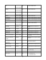
Group: security
NAME
VALUE
SECURITY
DESCRIPTION
(get/set)
user_i0_name
string[64]
6/7
User’s name of root
user_i<1~20>_name
string[64]
6/7
User’s name
49
user_i0_pass
string [64]
6/6
Root’s password
user_i<1~20>_pass
string [64]
7/6
User’s password
user_i0_privilege
admin
6/7
Root’s privilege
user_i<1~20>_ privilege
viewer,
6/6
User’s privilege.
SECURITY
DESCRIPTION
operator,
admin
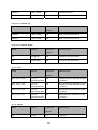
Group: network
NAME
VALUE
(get/set)
type
lan,
6/6
Network connection type
6/6
1 => get ipaddress, subnet, router,
dns1, dns2 from DHCP server at
next reboot
pppoe
resetip
<boolean>
0 => use preset ipaddress, subnet,
rounter, dns1, and dns2
ipaddress
<ip address>
6/6
IP address of server
subnet
<ip address>
6/6
subnet mask
router
<ip address>
6/6
default gateway
dns1
<ip address>
6/6
primary DNS server
dns2
<ip address>
6/6
secondary DNS server
wins1
<ip address>
6/6
primary WINS server
wins2
<ip address>
6/6
secondary WINS server
VALUE
SECURITY
DESCRIPTION
Subgroup of network: ftp
NAME
(get/set)
port
21, 1025~65535
6/6
50
local ftp server port
Subgroup of network: http
NAME
VALUE
SECURITY
DESCRIPTION
(get/set)
port
80, 1025 ~
65535
6/6
HTTP port
alternateport
1025~65535
6/6
Alternative HTTP port
authmode
basic,
1/6
HTTP authentication mode
digest
s0_accessname
string[32]
1/6
Http server push access name for
stream 1
s1_accessname
string[32]
1/6
Http server push access name for
stream 2
SECURITY
DESCRIPTION
Subgroup of network: rtsp
NAME
VALUE
(get/set)
port
554, 1025 ~
65535
6/6
RTSP port
authmode
disable,
1/6
RTSP authentication mode
basic,
digest
s0_accessname
string[32]
1/6
RTSP access name for stream1
s1_accessname
string[32]
1/6
RTSP access name for stream2
Subgroup of rtsp_s<0~(n-1)>: multicast, n is stream count
NAME
VALUE
SECURITY
DESCRIPTION
(get/set)
alwaysmulticast
<boolean>
4/4
Enable always multicast
ipaddress
<ip address>
4/4
Multicast IP address
videoport
1025 ~ 65535
4/4
Multicast video port
51
audioport
1025 ~ 65535
4/4
Multicast audio port
ttl
1 ~ 255
4/4
Mutlicast time to live value
Subgroup of network: rtp
NAME
VALUE
SECURITY
DESCRIPTION
(get/set)
videoport
1025 ~ 65535
6/6
video channel port for RTP
audioport
1025 ~ 65535
6/6
audio channel port for RTP
SECURITY
DESCRIPTION
Subgroup of network: pppoe
NAME
VALUE
(get/set)
user
string[128]
6/6
PPPoE account user name
pass
password[64]
6/6
PPPoE account password
VALUE
SECURITY
DESCRIPTION
Group: ipfilter
NAME
(get/set)
allow_i<0~9>_start
1.0.0.0 ~
255.255.255.255
6/6
Allowed starting IP address for RTSP
connection
allow_i<0~9>_end
1.0.0.0 ~
255.255.255.255
6/6
Allowed ending IP address for RTSP
connection
deny_i<0~9>_start
1.0.0.0 ~
255.255.255.255
6/6
Denied starting IP address for RTSP
connection
deny_i<0~9>_end
1.0.0.0 ~
255.255.255.255
6/6
Denied ending IP address for RTSP
connection
Group: videoin
NAME
VALUE
SECURITY
DESCRIPTION
(get/set)
freq
50, 60
4/4
52
frequency
whitebalance
auto,
4/4
auto, auto white balance
indoor,
indoor, 3200K
fluorescent,
fluorescent, 5500K
outdoor
outdoor, > 5500K
Group: videoin_c<0~(n-1)> for n channel products, m is stream number
NAME
VALUE
SECURITY
DESCRIPTION
(get/set)
color
0, 1
4/4
0 =>monochrome
1 => color
flip
<boolean>
4/4
flip the image
mirror
<boolean>
4/4
mirror the image
ptzstatus
<integer>
1/7
An 32-bits integer, each bit can be set
separately as follows:
Bit 0
=> Support camera control
function 0(not support), 1(support)
Bit 1
=> Build-in or external
camera. 0(external), 1(build-in)
Bit 2
=> Support pan operation.
0(not support), 1(support)
Bit 3
=> Support tilt operation.
0(not support), 1(support)
Bit 4
=> Support zoom operation.
0(not support), 1(support)
Bit 5
=> Support focus operation.
0(not support), 1(support)
text
string[16]
4/4
enclosed caption
imprinttimestamp
<boolean>
4/4
Overlay time stamp on video
maxexposure
1~120
4/4
Maximum exposure time
s<0~(m-1)>_codectype
mpeg4, mjpeg
4/4
video codec type
s<0~(m-1)>_keyinterval
1, 3, 5, 10, 30,
60, 90, 120
4/4
Key frame interval
s<0~(m-1)>_resolution
176x144,
4/4
Video resolution in pixel
320x240,
53
640x480,,
s<0~(m1)>_ratecontrolmode
cbr, vbr
4/4
cbr, constant bitrate
vbr, fix quality
s<0~(m-1)>_quant
1, 2, 3, 4, 5
4/4
quality of video when choosing vbr in
“ratecontrolmode”. 1 is worst quality
and 5 is the best quality.
s<0~(m-1)>_bitrate
20000,
4/4
set bit rate in bps when choose cbr in
“ratecontrolmode”
4/4
set maximum frame rate in fps
7/6
Force I frame
30000,
40000,
50000,
64000,
128000,
256000,
384000,
512000,
768000,
1000000,
1200000,
1500000,
2000000,
3000000,
4000000
s<0~(m-1)>_maxframe
1, 2, 3, 5, 10, 15,
20, 25,
30 (only for
NTSC or 60Hz )
s<0~(m-1)>_forcei
1
Group: audioin_c<0~(n-1)> for n channel products
NAME
VALUE
SECURITY
DESCRIPTION
(get/set)
source
micin,
4/4
54
micin => use external microphone
input
linein
linein => use line input, i.e. internal
microphone
mute
0, 1
4/4
Enable audio mute
gain
0~31
4/4
Gain of input
boostmic
0, 1
4/4
Enable microphone boost
s<0~(m-1)>_codectype
aac4, gamr
4/4
set audio codec type for input
s<0~(m-1)>_aac4_bitrate
16000,
4/4
set AAC4 bitrate in bps
4/4
set AMR bitrate in bps
32000,
48000,
64000,
96000,
128000
s<0~(m-1)>_gamr_bitrate
4750,
5150,
5900,
6700,
7400,
7950,
10200,
12200
Group: image_c<0~(n-1)> for n channel products
NAME
VALUE
SECURITY
DESCRIPTION
(get/set)
brightness
-5 ~ 5
4/4
Adjust brightness of image according
to mode settings.
saturation
-5 ~ 5
4/4
Adjust saturation of image according
to mode settings.
contrast
-5 ~ 5
4/4
Adjust contrast of image according to
55
mode settings.
hue
-5 ~ 5
4/4
Adjust hue of image according to
mode settings.
Group: motion_c<0~(n-1)> for n channel product
NAME
VALUE
SECURITY
DESCRIPTION
(get/set)
enable
<boolean>
4/4
enable motion detection
win_i<0~2>_enable
<boolean>
4/4
enable motion window 1~3
win_i <0~2>_name
string[14]
4/4
name of motion window 1~3
win_i <0~2>_left
0 ~ 320
4/4
Left coordinate of window position.
win_i <0~2>_top
0 ~ 240
4/4
Top coordinate of window position.
win_i <0~2>_width
0 ~ 320
4/4
Width of motion detection window.
win_i<0~2>_height
0 ~ 240
4/4
Height of motion detection window.
win_i<0~2>_objsize
0 ~ 100
4/4
Percent of motion detection window.
win_i<0~2>_sensitivity
0 ~ 100
4/4
Sensitivity of motion detection
window.
Group: ddns
NAME
VALUE
SECURITY
DESCRIPTION
(get/set)
enable
<boolean>
6/6
Enable or disable the dynamic dns.
provider
Safe100,
6/6
Safe100 => safe100.net
DyndnsDynamic => dyndns.org
(dynamic)
DyndnsDynamic,
DyndnsCustom,
TZO,
DyndnsCustom => dyndns.org
(custom)
DHS,
TZO => tzo.com
DynInterfree,
DHS => dhs.org
PeanutHull,
DynInterfree =>dyn-interfree.it
CustomSafe100
PeanutHull => peanut hull
CustomSafe100 =>
56
Custom server using safe100 method
<provider>_hostname
string[128]
6/6
Your dynamic hostname.
<provider>_username
email
string[64]
6/6
Your user or email to login ddns
service provider
<provider>_passwordk
ey
string[64]
6/6
Your password or key to login ddns
service provider
<provider>_servernam
e
string[128]
6/6
The server name for safe100.
(This field only exists for provider is
customsafe100)
Group: upnppresentation
NAME
VALUE
SECURITY
DESCRIPTION
(get/set)
enable
<boolean>
6/6
Enable or disable the UPNP
presentation service.
VALUE
SECURITY
DESCRIPTION
Group: upnpportforwarding
NAME
(get/set)
enable
<boolean>
6/6
Enable or disable the UPNP port
forwarding service.
upnpnatstatus
0~3
6/7
The status of UpnP port forwarding,
used internally.
0 is OK, 1 is FAIL, 2 is no IGD router,
3 is no need to do port forwarding
Group: syslog
NAME
VALUE
SECURITY
DESCRIPTION
(get/set)
enableremotelog
<boolean>
6/6
enable remote log
serverip
<IP address>
6/6
Log server IP address
serverport
514,
1025~65535
6/6
Server port used for log
level
0~7
6/6
The levels to distinguish the
57
importance of information.
0: LOG_EMERG
1: LOG_ALERT
2: LOG_CRIT
3: LOG_ERR
4: LOG_WARNING
5: LOG_NOTICE
6: LOG_INFO
7: LOG_DEBUG
Group: privacymask_c<0~(n-1)> for n channel product
NAME
VALUE
SECURITY
DESCRIPTION
(get/set)
enable
<boolean>
4/4
Enable the privacy mask
win_i<0~4>_enable
<boolean>
4/4
Enable the privacy mask window
win_i<0~4>_name
string[14]
4/4
The name of privacy mask window
win_i<0~4>_left
0 ~ 320/352
4/4
Left coordinate of window position.
win_i<0~4>_top
0 ~ 240/288
4/4
Top coordinate of window position.
win_i<0~4>_width
0 ~ 320/352
4/4
Width of privacy mask window
win_i<0~4>_height
0 ~ 240/288
4/4
Height of privacy mask window
Group: capability
NAME
VALUE
SECURITY
DESCRIPTION
(get/set)
api_http_version
0200a
0/7
The HTTP API version.
bootuptime
<positive integer>
0/7
The server bootup time
nir
0,
0/7
number of IR interface
0/7
number of digital input
<positive integer>
ndi
0,
<positive integer>
58
ndo
0,
0/7
number of digital output
0/7
number of audio input
0/7
number of audio output
<positive integer>
naudioin
0,
<positive integer>
naudioout
0,
<positive integer>
nvideoin
<positive integer>
0/7
number of video input
nmediastream
<positive integer>
0/7
number of media stream per channel
nvideosetting
<positive integer>
0/7
number of video settings per channel
naudiosetting
<positive integer>
0/7
number of audio settings per channel
nuart
0,
0/7
number of UART interface
<positive integer>
ptzenabled
< boolean >
0/7
indicate whether to support PTZ
control
protocol_https
< boolean >
0/7
indicate whether to support http over
SSL
protocol_rtsp
< boolean >
0/7
indicate whether to support rtsp
protocol_sip
<boolean>
0/7
indicate whether to support sip
protocol_maxconnection
<positive integer>
0/7
The maximum allowed simultaneous
connections
protocol_rtp_multicast_
<boolean>
0/7
indicate whether to support scalable
multicast
<boolean>
0/7
indicate whether to support
backchannel multicast
protocol_rtp_tcp
<boolean>
0/7
indicate whether to support rtp over
tcp
protocol_rtp_http
<boolean>
0/7
indicate whether to support rtp over
http
protocol_spush_mjpeg
<boolean>
0/7
indicate whether to support server
push motion jpeg
protocol_snmp
<boolean>
0/7
indicate whether to support snmp
videoin_type
0, 1, 2
0/7
0 => Interlaced CCD
scalable
protocol_rtp_multicast_
backchannel
1 => Progressive CCD
59
2 =>
videoin_resolution
<a list of the
available
resolution
separates by
comma)
0/7
available resolutions list
videoin_codec
<a list of the
available codec
types separaters
by comma)
0/7
available codec list
videoout_codec
<a list of the
available codec
types separaters
by comma)
0/7
available codec list
audio_aec
<boolean>
0/7
indicate whether to support acoustic
echo cancellation
audio_extmic
<boolean>
0/7
indicate whether to support external
microphone input
audio_linein
<boolean>
0/7
indicate whether to support external
line input
audio_lineout
<boolean>
0/7
indicate whether to support line output
audio_headphoneout
<boolean>
0/7
indicate whether to support
headphone output
audioin_codec
<a list of the
available codec
types separaters
by comma)
0/7
available codec list
audioout_codec
<a list of the
available codec
types separaters
by comma)
0/7
available codec list
camctrl_httptunnel
<boolean>
0/7
Indicate whether to support the http
tunnel for camera control
uart_httptunnel
<boolean>
0/7
Indicate whether to support the http
tunnel for uart transfer
transmission_mode
Tx,
0/7
Indicate what kind of transmission
mode the machine used. TX: server,
Rx: receiver box, Both: DVR?.
Rx,
Both
network_wire
<boolean>
0/7
Indicate whether to support the
Ethernet
network_wireless
<boolean>
0/7
Indicate whether to support the
wireless
60
wireless_802dot11b
<boolean>
0/7
Indicate whether to support the
wireless 802.11b+
wireless_802dot11g
<boolean>
0/7
Indicate whether to support the
wireless 802.11g
wireless_encrypt_wep
<boolean>
0/7
Indicate whether to support the
wireless WEP
wireless_encrypt_wpa
<boolean>
0/7
Indicate whether to support the
wireless WPA
wireless_encrypt_wpa2
<boolean>
0/7
Indicate whether to support the
wireless WPA2
Group: event_i<0~2>
PARAMETER
VALUE
SECURITY
DESCRIPTION
(get/set)
name
string[40]
6/6
The identification of this entry
enable
0, 1
6/6
To enable or disable this event.
priority
0, 1, 2
6/6
Indicate the priority of this event.
“0” indicates low priority.
“1” indicates normal priority.
“2” indicates high priority.
delay
1~999
6/6
Delay seconds before detect next event.
trigger
boot,
6/6
Indicate the trigger condition.
di,
“boot” indicates system boot.
motion,
“di” indicates digital input.
seq,
“motion” indicates video motion detection.
“seq” indicates periodic condition.
di
<integer>
6/6
Indicate which di detected.
This field is required when trigger condition is
“di”.
One bit represents one digital input. The LSB
indicates DI 0.
61
mdwin
<integer>
6/6
Indicate which motion detection windows
detected.
This field is required when trigger condition is
“md”.
One bit represents one window.
The LSB indicates the 1st window.
For example, to detect the 1st and 3rd windows,
set mdwin as 5.
inter
1~999
6/6
Interval of period snapshot in minute.
This field is used when trigger condition is
“seq”.
weekday
<interger>
6/6
Indicate which weekday is scheduled.
One bit represents one weekday.
The bit0 (LSB) indicates Saturday.
The bit1 indicates Friday.
The bit2 indicates Thursday.
The bit3 indicates Wednesday.
The bit4 indicates Tuesday.
The bit5 indicates Monday.
The bit6 indicates Sunday.
For example, to detect events on Friday and
Sunday, set weekday as 66.
begintime
hh:mm
6/6
Begin time of weekly schedule.
endtime
hh:mm
6/6
End time of weekly schedule.
(00:00 ~ 24:00 means always.)
action_do_i<0~(ndo1)>_enable
0, 1
6/6
To enable or disable trigger digital output.
action_do_i<0~(ndo1)>_duration
1~999
6/6
The duration of digital output is triggered in
seconds.
6/6
To enable or disable this server action.
action_server_i<0~4>_en 0, 1
able
The default value is 0.
action_server_i<0~4>_m NULL, 0~4
edia
6/6
The index of attached media.
62
Group: server_i<0~4>
PARAMETER
VALUE
SECURITY
DESCRIPTION
(get/set)
name
string[40]
6/6
The identification of this entry
type
email,
6/6
Indicate the server type.
ftp,
“email” is email server.
http,
“ftp” is ftp server.
ns
“http” is http server.
“ns” is network storage.
http_url
string[128]
6/6
The url of http server to upload.
http_username
string[64]
6/6
The username to login in the server.
http_passwd
string[64]
6/6
The password of the user.
ftp_address
string[128]
6/6
The ftp server address
ftp_username
string[64]
6/6
The username to login in the server.
ftp_passwd
string[64]
6/6
The password of the user.
ftp_port
0~65535
6/6
The port to connect the server.
ftp_location
string[128]
6/6
The location to upload or store the media.
ftp_passive
0, 1
6/6
To enable or disable the passive mode.
0 is to disable the passive mode.
1 is to enable the passive mode.
email_address
string[128]
6/6
The email server address
email_username
string[64]
6/6
The username to login in the server.
email_passwd
string[64]
6/6
The password of the user.
email_senderemail
string[128]
6/6
The email address of sender.
email_recipientemail
string[128]
6/6
The email address of recipient.
ns_location
string[128]
6/6
The location to upload or store the media.
ns_username
string[64]
6/6
The username to login in the server.
ns_passwd
string[64]
6/6
The password of the user.
ns_workgroup
string[64]
6/6
The workgroup for network storage.
63
Group: media_i<0~4>
PARAMETER
VALUE
SECURITY
DESCRIPTION
(get/set)
name
string[40]
6/6
The identification of this entry
type
snapshot,
6/6
The media type to send to the server or store by
the server.
6/6
Indicate the source of media stream.
systemlog
videoclip
snapshot_source
<integer>
0 means the first stream.
1 means the second stream and etc.
snapshot_prefix
string[16]
6/6
Indicate the prefix of the filename.
snapshot_datesuffix
0, 1
6/6
To add date and time suffix to filename or not.
1 means to add date and time suffix.
0 means not to add it.
snapshot_preevent
0~7
6/6
It indicates the number of pre-event images.
snapshot_postevent
0~7
6/6
The number of post-event images.
videoclip_source
<integer>
6/6
Indicate the source of media stream.
0 means the first stream.
1 means the second stream and etc.
videoclip_prefix
string[16]
6/6
Indicate the prefix of the filename.
videoclip_preevent
0~9
6/6
It indicates the time of pre-event recording in
seconds.
videoclip_maxduration
1 ~ 10
6/6
The time of maximum duration of one video clip
in seconds.
videoclip_maxsize
50 ~ 1500
6/6
The maximum size of one video clip file in
Kbytes.
VALUE
SECURITY
DESCRIPTION
Group: record_i<0~1>
PARAMETER
(get/set)
name
string[40]
6/6
The identification of this entry
64
enable
0, 1
6/6
To enable or disable this recoding.
priority
0, 1, 2
6/6
Indicate the priority of this recoding.
“0” indicates low priority.
“1” indicates normal priority.
“2” indicates high priority.
source
<integer>
6/6
Indicate the source of media stream.
0 means the first stream.
1 means the second stream and etc.
weekday
<interger>
6/6
Indicate which weekday is scheduled.
One bit represents one weekday.
The bit0 (LSB) indicates Saturday.
The bit1 indicates Friday.
The bit2 indicates Thursday.
The bit3 indicates Wednesday.
The bit4 indicates Tuesday.
The bit5 indicates Monday.
The bit6 indicates Sunday.
For example, to detect events on Friday and
Sunday, set weekday as 66.
begintime
hh:mm
6/6
Begin time of weekly schedule.
endtime
hh:mm
6/6
End time of weekly schedule.
(00:00~24:00 means always.)
prefix
string[16]
6/6
Indicate the prefix of the filename.
cyclesize
<integer>
6/6
The maximum size for cycle recording in
Kbytes.
maxfilesize
200~6000
6/6
The max size for one file in Kbytes
Drive the digital output
Note: This request requires the privilege of viewer.
Method: GET/POST
65
Syntax:
http://<servername>/cgi-bin/dido/setdo.cgi?do1=<state>[&do2=<state>]
[&do3=<state>][&do4=<state>][&return=<return page>]
Where state is 0, 1. “0” means inactive or normal state while “1” means active or triggered state.
PARAMETER
VALUE
DESCRIPTION
do<num>
0, 1
0 – inactive, normal state
1 – active, triggered state
return
<return page>
Redirect to the page <return page> after the parameter is
assigned. The <return page> can be a full URL path or
relative path according the the current path. If you omit this
parameter, it will redirect to an empty page.
Example: Drive the digital output 1 to triggered state and redirect to an empty page
http://myserver/cgi-bin/dido/setdo.cgi?do1=1
Query status of the digital input
Note: This request requires the privilege of viewer.
Method: GET/POST
Syntax:
http://<servername>/cgi-bin/dido/getdi.cgi?[di0][&di1][&di2][&di3]
If no parameter is specified, all the status of digital input will be returned.
Return:
HTTP/1.0 200 OK\r\n
Content-Type: text/plain\r\n
Content-Length: <length>\r\n
\r\n
66
[di0=<state>]\r\n
[di1=<state>]\r\n
[di2=<state>]\r\n
[di3=<state>]\r\n
where <state> can be 0 or 1.
Example: Query the status of digital input 1
Request:
http://myserver/cgi-bin/dido/getdi.cgi?di1
Response:
HTTP/1.0 200 OK\r\n
Content-Type: text/plain\r\n
Content-Length: 7\r\n
\r\n
di1=1\r\n
Query status of the digital output
Note: This request requires the privilege of viewer.
Method: GET/POST
Syntax:
http://<servername>/cgi-bin/dido/getdo.cgi?[do0][&do1][&do2][&do3]
If no parameter is specified, all the status of digital output will be returned.
Return:
HTTP/1.0 200 OK\r\n
Content-Type: text/plain\r\n
Content-Length: <length>\r\n
\r\n
67
[do0=<state>]\r\n
[do1=<state>]\r\n
[do2=<state>]\r\n
[do3=<state>]\r\n
where <state> can be 0 or 1.
Example: Query the status of digital output 1
Request:
http://myserver/cgi-bin/dido/getdo.cgi?do1
Response:
HTTP/1.0 200 OK\r\n
Content-Type: text/plain\r\n
Content-Length: 7\r\n
\r\n
do1=1\r\n
Capture single snapshot
Note: This request require normal user privilege
Method: GET/POST
Syntax:
http://<servername>/cgi-bin/viewer/video.jpg?[channel=<value>][&resolution=<value>]
[&quality=<value>]
If the user requests the size larger than all stream setting on the server, this request will failed!
PARAMETER
VALUE
DEFAULT
DESCRIPTION
channel
0~(n-1)
0
the channel number of video source
resolution
<available
resolution>
0
The resolution of image
68
quality
1~5
3
The quality of image
Server will return the most up-to-date snapshot of selected channel and stream in JPEG format. The
size and quality of image will be set according to the video settings on the server.
Return:
HTTP/1.0 200 OK\r\n
Content-Type: image/jpeg\r\n
[Content-Length: <image size>\r\n]
<binary JPEG image data>
Account management
Note: This request requires administrator privilege
Method: GET/POST
Syntax:
http://<servername>/cgi-bin/admin/editaccount.cgi?
method=<value>&username=<name>[&userpass=<value>][&privilege=<value>]
[&privilege=<value>][…][&return=<return page>]
PARAMETER
VALUE
DESCRIPTION
method
add
Add an account to server. When using this method,
“username” field is necessary. It will use default value of other
fields if not specified.
delete
Remove an account from server. When using this method,
“username” field is necessary, and others are ignored.
edit
Modify the account password and privilege. When using this
method, “username” field is necessary, and other fields are
optional. If not specified, it will keep original settings.
username
<name>
The name of user to add, delete or edit
userpass
<value>
The password of new user to add or that of old user to modify.
The default value is an empty string.
69
privilege
return
<value>
The privilege of user to add or to modify.
viewer
viewer’s privilege
operator
operator’s privilege
admin
administrator’s privilege
<return page>
Redirect to the page <return page> after the parameter is
assigned. The <return page> can be a full URL path or relative
path according the the current path. If you omit this parameter,
it will redirect to an empty page.
System logs
Note: This request require administrator privilege
Method: GET/POST
Syntax:
http://<servername>/cgi-bin/admin/syslog.cgi
Server will return the up-to-date system log.
Return:
HTTP/1.0 200 OK\r\n
Content-Type: text/plain\r\n
Content-Length: <syslog length>\r\n
\r\n
<system log information>\r\n
Upgrade firmware
Note: This request requires administrator privilege
Method: POST
Syntax:
http://<servername>/cgi-bin/admin/upgrade.cgi
70
Post data:
fimage=<file name>[&return=<return page>]\r\n
\r\n
<multipart encoded form data>
Server will accept the upload file named <file name> to be upgraded the firmware and return with
<return page> if indicated.
IP filtering
Note: This request requires administrator access privilege
Method: GET/POST
Syntax:
http://<servername>/cgi-bin/admin/ipfilter.cgi?
method=<value>&[start=<ipaddress>&end=<ipaddress>][&index=<value>]
[&return=<return page>]
PARAMETER
VALUE
DESCRIPTION
Method
addallow
Add a set of allow IP address range to server. Start and
end parameters must be specified. If the index parameter
is specified, it will try to add starting from index position.
adddeny
Add a set of deny IP address range to server. Start and
end parameters must be specified. If the index parameter
is specified, it will try to add starting from index position.
deleteallow
Remove a set of allow IP address range from server. If
start and end parameters are specified, it will try to remove
the matched IP address. If index is specified, it will try to
remove the address from given index position. [start, end]
parameters have higher priority then the [index] parameter.
deletedeny
Remove a set of deny IP address range from server. If start
and end parameters are specified, it will try to remove the
matched IP address. If index is specified, it will try to
remove the address from given index position. [start, end]
parameters have higher priority then the [index] parameter.
<ip address>
The start IP address to add or to delete.
start
71
end
<ip address>
The end IP address to add or to delete.
index
<value>
The start position to add or to delete.
return
<return page>
Redirect to the page <return page> after the parameter is
assigned. The <return page> can be a full URL path or
relative path according the the current path. If you omit this
parameter, it will redirect to an empty page.
RTSP SDP
Note: This request requires viewer access privilege
Method: GET/POST
Syntax:
http://<servername>/viewer/<0~(n-1)>/<network_accessname_<0~(m-1)>>
rtsp://<servername>/<0~(n-1)>/<network_accessname_<0~(m-1)>>
“n” is the channel number and “m” is the stream number.
You can get the SDP by HTTP or just describe by RTSP protocol directly. For detailed streaming
protocol, please refer to “control signaling” and “data format” documents.
72
D. Technical data
Video
Compression: MPEG-4 & MJPEG
Max. Resolution: 640x480 Pixel
Available resolutions: 640x480, 320x240,
176x144
Framerate: max. 25 fps
Network
10/100 Mbps Ethernet, RJ-45
Protocols (among others): IPv4,TCP/IP, HTTP,
UPnP, RTSP/RTP/RTCP, IGMP, SMTP, FTP,
DHCP, NTP, DNS, DDNS, PPPoE
W-LAN 802.11b/g (only TV7222/TV7223)
Audio
GSM-AMR, Bit rate: 4.75 Kbit/s
MPEG-4 AAC, Bit rate: 16 Kbit/s ~ 128 Kbit/s
Two way Audio
Built in microphone
Microphone input
Audio output
Mute
Safety
Multi level password security
IP address filter
W-LAN: WEP, WPA-PSK, WPA2
Streaming
Dual streaming of MPEG-4 and MJPEG
MPEG-4 streaming over UDP, TCP or HTTP
MPEG-4 multicast streaming
MPEG-4 streaming over RTSP
MJPEG streaming over HHTP
Picture settings
Size, quality, bitrate
Timestamp and title on video
Flip & Mirror
Brightness, contrast, saturation
AGC, AWB, AEC
IR cut filter: Auto, manual, schedule, digital input
(only TV7222, TV7223)
Backlight compensation (BLC)
Privacy masking (5 areas, user selectable)
System
Flash: 8MB
RAM: 64 MB
Image sensor: ¼ inch Progressive Scan CCD
sensor
Shutter: 1/30 Sek. ~ 1/50000 Sek.
LED display: 2 color Status LED
IR cut filter for day/night function (only
TV7222/TV7223)
Event management
Video motion detection
Digital input and output
Event notification over HTTP, SMTP, FTP
Local recording on PC in MP4 file
Power supply
12VDC / max. 750 mA
802.3af POE (Power over Ethernet) (only
TV7220, TV7222)
Environment
Temperature: 0~35°C
Humiditiy: 20%~80% RH
System requirements
OS: Windows XP/2003/Vista
Browser: Internet Explorer, Mozilla Firefox
Mobile: 3GPP-Player
Real Player 10.5
Quicktime 6.5
Packet Video Player 3.0
VLC Player
73
E. Licence information
GNU GPL
We point at the fact that thenetwork cameras TV7220, TV7221, TV7222 and TV7223 among other
things include Linux software source codes that are licensed under the GNU General Public Licence
(GPL). To assure a GPL compliant usage of the used source codes we point at the licence terms of
GPL.
Licence text
The licence text of the GNU General Public Licence can be found on the included software CD or on
the ABUS Security-Center Homepage under http://www.abus-sc.de/DE/ServiceDownloads/Software?q=GPL
Source Code
The used source codes are available on the ABUS Security-Center Homepage under
http://www.abus-sc.de/DE/Service-Downloads/Software?q=GPL
for free download.
Operation of the total system
With a download of the software packages (source codes) it is not possible to built a running total
system. Therefor additional software applications and the network camera hardware is needed.
74
F. License
MPEG-4 AAC Technology
THIS PRODUCT IS LICENSED UNDER THE MPEG-4 AAC AUDIO PATENT LICENSE. THIS
PRODUCT MAY NOT BE DECOMPILED, REVERSE-ENGINEERED OR COPIED, EXCEPT
REGARD TO PC SOFTWARE, YOU MAY MAKE SINGLE COPIES FOR ARCHIVAL PURPOSES.
FOR MORE INFORMATION, PLEASE REFER TO HTTP://WWW.VIALICENSING.COM.
MPEG-4 Visual Technology
THIS PRODUCT IS LICENSED UNDER THE MPEG-4 VISUAL PATENT PORTFOLIO LICENSE FOR
THE PERSONAL AND NON-COMMERCIAL USE OF A CONSUMER FOR (i) ENCODING VIDEO IN
COMPLIANCE WITH THE MPEG-4 VISUAL STANDARD ("MPEG-4 VIDEO") AND/OR (ii)
DECODING MPEG-4 VIDEO THAT WAS ENCODED BY A CONSUMER ENGAGED IN A
PERSONAL AND NON-COMMERCIAL ACTIVITY AND/OR WAS OBTAINED FROM A VIDEO
PROVIDER LICENSED BY MPEG LA TO PROVIDE MPEG-4 VIDEO. NO LICENSE IS GRANTED
OR SHALL BE IMPLIED FOR ANY OTHER USE. ADDITIONAL INFORMATION INCLUDING THAT
RELATING TO PROMOTIONAL, INTERNAL AND COMMERCIAL USES AND LICENSING MAY BE
OBTAINED FROM MPEG LA, LLC. SEE
HTTP://WWW.MPEGLA.COM.
AMR-NB Standard
THIS PRODUCT IS LICENSED UNDER THE AMR-NB STANDARD PATENT LICENSE
AGREEMENT. WITH RESPECT TO THE USE OF THIS PRODUCT, THE FOLLOWING
LICENSORS’ PATENTS MAY APPLY:
TELEFONAKIEBOLAGET ERICSSON AB: US PAT. 6192335; 6275798; 6029125; 6424938;
6058359. NOKIA CORPORATION: US PAT. 5946651; 6199035. VOICEAGE CORPORATION: AT
PAT. 0516621; BE PAT. 0516621; CA PAT. 2010830; CH PAT. 0516621; DE PAT. 0516621; DK PAT.
0516621; ES PAT. 0516621; FR PAT. 0516621; GB PAT. 0516621; GR PAT. 0516621; IT PAT.
0516621; LI PAT. 0516621; LU PAT. 0516621; NL PAT. 0516621; SE PAT 0516621; US PAT
5444816; AT PAT. 819303/AT E 198805T1; AU PAT. 697256; BE PAT. 819303; BR PAT. 9604838-7;
CA PAT. 2216315; CH PAT. 819303; CN PAT. ZL96193827.7; DE PAT. 819303/DE69611607T2; DK
PAT. 819303; ES PAT. 819303; EP PAT. 819303; FR PAT. 819303; GB PAT. 819303; IT PAT.
819303; JP PAT. APP. 8-529817; NL PAT. 819303; SE PAT. 819303; US PAT. 5664053. THE LIST
MAY BE UPDATED FROM TIME TO TIME BY LICENSORS AND A CURRENT VERSION OF WHICH
IS AVAILABLE ON LICENSOR’S WEBSITE AT HTTP://WWW.VOICEAGE.COM.
75