1
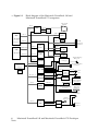
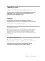
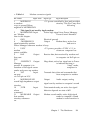
®
Macintosh PowerBook 140
and Macintosh PowerBook
170
Developer Note
®
Developer Note
Developer Technical Publications
© Apple Computer, Inc. 1991
ð
APPLE COMPUTER, INC.
© 1991, Apple Computer,
Inc.
All rights reserved.
No part of this publication
may be reproduced, stored in
a retrieval system, or
transmitted, in any form or
by any means, mechanical,
electronic, photocopying,
recording, or otherwise,
without prior written
permission of Apple
Computer, Inc. Printed in the
United States of America.
trademarks of International
Typeface Corporation.
MacDraw is a registered
trademark of Claris
Corporation.
Microsoft is a registered
trademark of Microsoft
Corporation.
LIMITED WARRANTY ON
MEDIA AND
R EPLACEMENT
If you discover physical
defects in the manual or in
The Apple logo is a
the media on which a
registered trademark of
software product is
Apple Computer, Inc. Use of
distributed, APDA will
the “keyboard” Apple logo
replace the media or
manual at no charge to you
(Option-Shift-K) for
commercial purposes without provided you return the
item to be replaced with
the prior written consent of
proof of purchase to APDA.
Apple may constitute
trademark infringement and
ALL IMPLIED
unfair competition in
WARRANTIES ON THIS
violation of federal and
MANUAL, INCLUDING
state laws.
IMPLIED WARRANTIES
OF MERCHANTABILITY
Apple Computer, Inc.
AND FITNESS FOR A
20525 Mariani Avenue
PARTICULAR PURPOSE,
Cupertino, CA 95014-6299
ARE LIMITED IN
408-996-1010
DURATION TO NINETY
Apple, the Apple logo,
(90) DAYS FROM THE
APDA, AppleLink,
DATE OF THE ORIGINAL
AppleTalk, LaserWriter,
RETAIL PURCHASE OF
Macintosh, and SANE are
THIS PRODUCT.
trademarks of Apple
Computer, Inc., registered in Even though Apple has
the United States and other reviewed this manual,
APPLE MAKES NO
countries.
WARRANTY OR
Apple DeskTop Bus, Balloon REPRESENTATION,
Help, PowerBook,
EITHER EXPRESS OR
QuickDraw, and SuperDrive IMPLIED, WITH RESPECT
are trademarks of Apple
TO THIS MANUAL, ITS
Computer, Inc.
QUALITY, ACCURACY,
MERCHANTABILITY, OR
Classic is a registered
FITNESS FOR A
trademark, licensed to
PARTICULAR PURPOSE.
Apple Computer, Inc.
AS A RESULT, THIS
Adobe Illustrator and
MANUAL IS SOLD “AS
PostScript are registered
IS,” AND YOU, THE
trademarks of Adobe
PURCHASER, ARE
Systems Incorporated.
ASSUMING THE ENTIRE
RISK AS TO ITS QUALITY
ITC Garamond and ITC Zapf
AND ACCURACY.
Dingbats are registered
IN NO EVENT WILL
APPLE BE LIABLE FOR
DIRECT, INDIRECT,
SPECIAL, INCIDENTAL,
OR CONSEQUENTIAL
DAMAGES RESULTING
FROM ANY DEFECT OR
INACCURACY IN THIS
MANUAL, even if advised
of the possibility of such
damages.
THE WARRANTY AND
REMEDIES SET FORTH
ABOVE ARE EXCLUSIVE
AND IN LIEU OF ALL
OTHERS, ORAL OR
WRITTEN, EXPRESS OR
IMPLIED. No Apple
dealer, agent, or employee
is authorized to make any
modification, extension, or
addition to this warranty.
Some states do not allow
the exclusion or limitation
of implied warranties or
liability for incidental or
consequential damages, so
the above limitation or
exclusion may not apply to
you. This warranty gives
you specific legal rights,
and you may also have
other rights which vary
from state to state.
Contents
Figures and Tables / v
Preface / vii
About this note / vii
Supplemental reference documents / vii
1 The Hardware / 1
Introduction / 2
Features / 2
Design architecture / 3
Machine identification / 4
Compatibility issues / 6
Floppy disks / 6
External SCSI connector / 6
SCSI and SCC implementation / 6
Sound input/output hardware / 7
On-board mathematics coprocessor (FPU) / 7
Hardware overview / 8
Main processor / 8
Memory mapping / 8
Custom integrated circuits / 11
CPU GLU / 11
DDC (Display Driver Chip) / 11
Miscellaneous GLU / 11
ROM interface / 12
RAM interface / 12
RAM expansion / 13
RAM expansion connector signals / 15
RAM expansion card design guide / 17
Floppy disk interface / 19
SCC and SCSI interfaces / 20
SCC / 20
SCSI / 21
Internal hard disk drive / 23
iii
Hard disk drive design considerations / 23
Power requirements for 40 MB hard disk drive / 23
Power requirements for 20 MB hard disk drive / 24
Sound interface / 26
VIA interface / 27
Video interface / 27
Flat-panel display and backlighting / 27
Power Manager / 28
Power states / 28
Shutdown feature / 29
Power cycling / 30
Guidelines for developing application software for a
power-cycling environment / 31
A/C power adapter / 31
Modem interface / 32
Modem card electrical interface / 32
Modem card hardware interface / 34
Physical design guide for a modem card / 34
Modem power-control interface / 37
Modem operation / 38
Power-up/power-down timing / 38
Ring detection / 41
Modem card power requirements / 41
Telephone line electrical interface / 41
Modem specifications / 42
Compatibility and modulation / 42
Transmit carrier frequencies / 42
Guard tone frequencies and transmit levels (CCITT
only) / 43
Answer tone frequency / 43
Received signal frequency tolerance / 43
Calling tone / 43
Keyboard overview / 43
Keyboard layouts / 43
Caps Lock modification / 45
2 The Software / 47
The ROM / 48
System software / 48
iv
Macintosh PowerBook 140 and Macintosh PowerBook 170 Developer
Note
Figures and Tables
1
The Hardware / 1
Figure 1-1 Block diagram of the Macintosh PowerBook
140 and Macintosh PowerBook 170 computers /
5
Figure 1-2 32-bit memory and detailed I/O map / 9
Figure 1-3 32-bit and 24-bit memory maps / 10
Figure 1-4 Location of modem and RAM expansion
connectors / 14
Figure 1-5 RAM expansion card design guide / 18
Figure 1-6 Envelope requirement for the 2.5-inch hard
disk
drive / 25
Figure 1-7 Typical A/C power adapter operating range /
32
Figure 1-8 Interface between the modem card and the
computer / 35
Figure 1-9 Modem card design guide / 36
Figure 1-10
Modem cold-start (initial power-up)
timing
diagram / 39
Figure 1-11
Modem warm-start timing diagram / 39
Figure 1-12
Complete power-up/power-down
sequence timing
diagram / 40
Figure 1-13
U.S. and ISO keyboard layouts / 44
Figure 1-14
Caps Lock “down” / 45
Figure 1-15
Caps Lock “up” / 45
Table 1-1
Table 1-2
Table 1-3
Table 1-4
RAM expansion connector signals / 15
Pinout for internal floppy disk connector / 19
Serial port pinouts / 20
Pinouts for internal and external HDI-30 SCSI
connectors / 22
Table 1-5 Power states / 29
Table 1-6 Modem connector signals / 33
Figures and Tables
v
vi
Macintosh PowerBook 140 and Macintosh PowerBook 170 Developer
Note
Preface
About this note
This developer note describes the Macintosh PowerBook 140 and
Macintosh PowerBook 170 computers and emphasizes features that
are new and different from those of the Macintosh Portable and the
Macintosh PowerBook 100 computers. This note assumes that you
are already familiar with both the capabilities and programming
requirements of Apple Macintosh computers, in particular the
Macintosh Portable computer. If you are unfamiliar with Macintosh
computers or would simply like more technical information on the
hardware, you may want to obtain copies of related technical
manuals. For information on how to obtain these manuals, see the
following section.
For more information
To supplement the information in this document, you might wish to obtain
related documentation such as Guide to the Macintosh Family Hardware,
second edition; Designing Cards and Drivers for the Macintosh Family,
second edition (third edition will soon be available), and Inside Macintosh,
Volumes I through VI. Copies of these manuals are available through APDA
(Apple Programmers and Developers Association). APDA offers convenient
worldwide access to over 300 development tools, resources, and training
products and to information for anyone interested in developing applications
on Apple platforms. Customers receive the quarterly APDA Tools Catalog,
featuring the most current versions of Apple development tools and the
most popular third-party development tools. Ordering is easy; there are no
membership fees, and application forms are not required for most of our
vii
products. APDA offers convenient payment and shipping options, including
site licensing.
viii Macintosh PowerBook 140 and Macintosh PowerBook 170 Developer
Note
To order products or get additional information, contact
APDA
Apple Computer, Inc.
20525 Mariani Avenue, M/S 33-G
Cupertino, CA 95014-6299
800-282-2732 (United States)
800-637-0029 (Canada)
408-562-3910 (International)
Fax: 1-408-562-3971
Telex: 171-576
AppleLink address: APDA
Preface
ix
Chapter 1 The Hardware
This chapter describes the major features of the Macintosh
PowerBook 140 and Macintosh PowerBook 170 computers,
and emphasizes the similarities and differences between
these computers, the original Macintosh Portable
computer, and other members of the Macintosh computer
family.
1
Introduction
The Macintosh PowerBook 140 and Macintosh PowerBook 170
computers are new laptop, battery-operated, portable Macintosh
computers weighing 6.8 pounds. They are smaller and lighter than the
current Macintosh Portable, offer improved state-of-the-art CPU
performance, are designed to be extremely rugged and portable, and
should appeal to anyone wishing to use a Macintosh computer away
from its usual environment (office, classroom, laboratory, and so on).
The Macintosh PowerBook 140 has a 68030 microprocessor running at
16 MHz, a backlit Film SuperTwist Nematic (FSTN) display, and a
built-in 20 MB hard disk. The more powerful Macintosh PowerBook
170 has a 68030 microprocessor running at 25 MHz, a 68882 FPU
(floating-point unit), a backlit active matrix display, and a built-in 40
MB hard disk. The Macintosh PowerBook 140 does not include a 68882
FPU. To enhance the overall capabilities of these portable computers,
expansion slots (connectors) are provided for RAM cards and modem
cards.
Features
This section lists the major features of the Macintosh PowerBook 140
and the Macintosh PowerBook 170 portable computers.
• Microprocessor: 68030 running at 25 MHz (Macintosh PowerBook
170) and 16 MHz (Macintosh PowerBook 140).
• Coprocessor: 68882 FPU (not available on Macintosh PowerBook
140).
• Read-only memory (ROM): 1 MB.
• Random-access memory (RAM): 2 MB of pseudostatic RAM
(PSRAM) on main logic board ; in addition, PowerBook 170 includes
2 MB RAM expansion card.
• RAM expansion: RAM expansion card that allows RAM expansion
in increments of
2 MB, 4 MB, or 6 MB.
2
Macintosh PowerBook 140 and Macintosh PowerBook 170 Developer
Note
• Video display: Macintosh PowerBook 170 has a flat-panel,
transreflective active matrix LCD (liquid crystal display); Macintosh
PowerBook 140 has a flat-panel, transmissive mode, FSTN LCD.
Both displays are 640 x 400 pixels, with on-demand CCFL (cold
cathode fluorescent lamp) backlighting.
• Floppy disk: one internal 20-pin floppy disk connector and one
internal 1.4 MB 19-mm Apple SuperDrive with Super Woz
Integrated Machine (SWIM) interface. Drive does not have
automatic inject feature.
• Hard disk: one 30-pin flex cable with HDI (high-density interface) 30pin SCSI (Small Computer System Interface) connector for internal
hard disk drive. The Macintosh PowerBook 170 has one internal 40
MB, 2.5-inch SCSI hard disk drive; the Macintosh PowerBook 140 has
one internal 20 MB, 2.5-inch SCSI hard disk drive.
• I/O (input/output): one HDI-30 SCSI connector for an external
device, one mini-DIN, 4-pin Apple Desktop Bus (ADB) port, two
mini-DIN 8-pin serial ports, and audio input and stereo output jacks;
no connector for an external floppy disk drive.
• Sound: enhanced Apple Sound Chip (ASC) that supports stereo
sound out.
• Keyboard: built-in 3.0-mm travel keyboard with centered pointing
device (30-mm trackball); no built-in keypad option.
• Modem: internal 20-pin connector for 2400-baud modem card with
send fax (modem is standard in Macintosh PowerBook 170, optional
in Macintosh PowerBook 140).
• Battery: 2.5 ampere-hour NiCad rechargeable battery; backup
provided by 3-V rechargable lithium battery.
• Power jack: external jack that provides the interface for the external
wall-mounted recharger/power adapter.
• Weight: 6.8 pounds.
• Size: 11.3 inches wide, 9.3 inches long, and 2.25 inches high.
Chapter 1
The Hardware
3
Design architecture
These new portable computers include many of the Macintosh Portable
computer’s architectural features such as power management, SWIM,
and Versatile Interface Adapter (VIA) functions. The powerful 68030
microprocessor replaces the 68HC000 microprocessor used in the
Macintosh Portable. A Combo chip, identical to that used in the
Macintosh IIsi and the Macintosh LC computers, combines the
functions of SCSI and SCC (Serial Communications Controller). Sound
input and output are implemented using an enhanced Apple Sound
Chip, low-power discrete audio output circuitry, and the Digitally
Filtered Audio Chip (DFAC).
One of the primary considerations in the design was power
conservation. A unique power cycling feature turns off the 68030
processor (and the 68882 coprocessor on the Macintosh PowerBook 170)
when they are not in use, thus drastically reducing power
consumption. PSRAM, the same as used in the backlit version of the
Macintosh Portable, replaces the SRAM (static RAM) used in the
original version of Macintosh Portable and has the advantage of
providing lower sleep current at reduced cost.
The design includes three new custom integrated circuits (ICs): CPU
GLU (General Logic Unit), Miscellaneous GLU, and the DDC (Display
Driver Chip). The CPU GLU serves as the interface to the circuits that
communicate with the main processor, the Miscellaneous GLU
provides the random logic functions for circuits that communicate
with the Power Manager, and the DDC provides access to a separate
SRAM to support the flat-panel display. Figure 1-1 is a block diagram
showing the relationships of the major components of the computers.
4
Macintosh PowerBook 140 and Macintosh PowerBook 170 Developer
Note
Machine identification
By using the Gestalt Manager (the successor to SysEnvirons), you can
determine whether your application is running on a Macintosh
PowerBook 140, a Macintosh PowerBook 170, or another Macintosh
model. You should first check for the appropriate machine selector
code (21 for both the Macintosh PowerBook 140 and the Macintosh
PowerBook 170). Next check for the presence or absence of an FPU, as
explained in “On-board Mathematics Coprocessor (FPU).” later in this
chapter. If the routine returns a selector code of 21 and also indicates
that an FPU is present, then your application is running on a
Macintosh PowerBook 170. A selector code of 21 together with the
absence of an FPU identifies the machine as a Macintosh PowerBook
140. A selector code other than 21 indicates some other Macintosh
model.
Chapter 1
The Hardware
5
• Figure 1-1
Block diagram of the Macintosh PowerBook 140 and
Macintosh PowerBook 170 computers
Flat-panel
display
A14–1
D31–16
DDC
A20–0
FPU
VD7–0
VA14–0
Video
RAM
A12–9
A4–1
D31–24
D31–0
A20–2
VIA1
MC68882
(not used on
PowerBook 140)
RTC
RAM
expansion
connector
D31–0
CPU
MC68030
Address bus
A31–0
D31–0
Data bus
D31–0
D31–24
D25, 24
A31–13, 1, 0
Data
buffers
I/O data
buffer
D31–0
D31–24
A20–2
D31–0
PSRAM
2 MB
D31–0
A19–2
ROM
1 MB
Power
manager
CPU GLU
Battery charger
and power
supply
External modem
connector
D31–24
Misc. GLU
Channel A
Port A
Drivers (modem)
and
Channel Breceivers Port B
(printer)
Battery
A6–4, 2, 1
Combo
SCC/SCSI
D31–24
SWIM
Serial
ports
Keyboard
Keyboard
processor
and
trackball
Internal floppy
disk connector connectors
D31–24
A12–9
Apple Desktop
Bus port
Internal hard disk
connector
External
SCSI port
External
sound jack
Sound
input jack
A11–0
Enhanced
ASC
DFAC
Filter/amp
Internal
speaker
6
Macintosh PowerBook 140 and Macintosh PowerBook 170 Developer
Note
Compatibility issues
Although the architecture of the new portable computers is based
partially on that of the original Macintosh Portable, it also incorporates
many new features, resulting in some possible hardware and software
compatibility issues. The rest of this section describes those new
features and related compatibility issues.
Floppy disks
The Macintosh PowerBook 140 and Macintosh PowerBook 170
computers have only one built-in 1.4 MB SuperDrive and do not have
a connector for an external floppy disk drive.
External SCSI connector
An HDI-30 connector provides the SCSI interface for external devices.
This connector is smaller and has a different pinout than the DB-25
SCSI connector used on previous Macintosh computers. Electrical
information is provided in the section “SCC and SCSI Interfaces” later
in this chapter.
SCSI and SCC implementation
The Combo chip combines the functions of SCSI and SCC and is
described in the section “SCC and SCSI Interfaces” later in this chapter.
Although this chip is software compatible with the previous
implementation of these functions, your applications may be
inoperable if they attempt to access the hardware directly.
Chapter 1
The Hardware
7
An application should use normal communications calls to talk to the
serial driver; it should never attempt to get direct access to the SCC
hardware. The serial chip is turned off when not in use; if your
application makes normal serial communications calls, the serial
driver knows how to turn the serial chip back on. However, an
application that attempts to go directly to the serial chip will wind up
talking to the chip when it is turned off, resulting in a loss of
communication.
8
Macintosh PowerBook 140 and Macintosh PowerBook 170 Developer
Note
Sound input/output hardware
Details on the sound system implementation are provided in the
section
“Sound Interface” later in this chapter. The sound interface uses an
enhanced version of the Apple Sound Chip (ASC) together with the
DFAC to provide compatibility with the
overall Macintosh sound input/output strategy. If your application
uses the Macintosh Sound Manager calls and does not try to access the
ASC hardware directly, it will work
as documented.
On-board mathematics coprocessor (FPU)
The 68882 FPU is a standard feature of the Macintosh PowerBook 170
computer but is not supported on the Macintosh PowerBook 140
computer. To ensure that your application is compatible with the
Macintosh PowerBook 170, the Macintosh PowerBook 140, and future
Macintosh computers that do not have FPUs, use the Gestalt Manager.
Using the Gestalt Manager allows you to determine the exact
configuration of the machine on which you are running.
If your application is provided in two versions, one that uses SANE
(Standard Apple Numerics Environment) software and another that
requires the FPU hardware to perform its numeric calculations, or if
the application makes a conditional branch to execute floating-point
instructions directly, then your application should check first for the
presence of an FPU.
Chapter 1
The Hardware
9
Hardware overview
This section provides a functional description of the processor,
memory, general logic, and I/O (input/output) interface systems.
Emphasis is placed on those systems that are new or different from
those of the earlier Macintosh Portable and other members of the
Macintosh computer family.
♦ Important Memory sizes, addresses, and other data are specific to
each type of Macintosh computer and are provided for
informational purposes only. To ensure that your
application software maintains compatibility across the
Macintosh line and to allow for future hardware
changes, you are strongly advised to use the Macintosh
Toolbox and Operating System routines wherever
provided. In particular, never use absolute addresses to
access hardware, because these addresses are different on
different models. ♦
Main processor
The 68030 microprocessors used in the Macintosh PowerBook 140 and
Macintosh PowerBook 170 run at system clock rates of 16 MHz and 25
MHz, respectively. The 68030 includes a built-in MMU (memory
management unit) that performs the necessary memory-mapping
functions. Floating-point operations in the Macintosh PowerBook 170
are provided by the 68882 mathematics coprocessor FPU. The
Macintosh PowerBook 140 does not include an FPU.
10
Macintosh PowerBook 140 and Macintosh PowerBook 170 Developer
Note
Memory mapping
Two memory address-mapping modes, a 24-bit mode and a 32-bit
mode, are implemented. This allows older software to use the 24-bit
address space and new software to use the full 32-bit address space.
Figure 1-2 shows the main 32-bit memory map and the 32-bit I/O
memory map decode of the system I/O address space from $5000 0000 to
$6000 0000. Figure 1-3 compares the system’s main 32-bit memory map
with the 24-bit memory map. Notice in Figure 1-3 that video space
resides at location $FEE0 0000 (32-bit mode) or $E0 0000 (24-bit mode)
and not in either RAM or I/O space. Also, you can access the I/O space
in 32-bit mode while maintaining a 24-bit mode offset of $F0 0000 for
compatibility. This is because all I/O devices wrap into $Fx xxxx space.
Chapter 1
The Hardware
11
• Figure 1-2
32-bit memory and detailed I/O map
Expansion I/O sp
(no DSACKs)
Reserv
Reserv
$FFFF FF
$FEFF FFF
$FEE0 00
Reserv
Video RA
Reserv
$6000 00
$5000 00
$4400 00
$4000 00
I/O
Reserv
ROM
Expansion
RAM
$0400 00
$0080 00
(Wrap)
RAM
$0000 00
8 MB maximum,
one continuous b
Reserv
CPU GLU regist
Reserv
Reserv
Reserv
Reserv
Reserv
Reserv
Reserv
Reserv
Reserv
Reserv
Reserv
Reserv
Reserv
Reserv
SWIM
Sound
SCSI (non D
SCSI (normal m
Reserved (SCSI
Reserved (SCC
Reserved (VIA2 w
Reserved (VIA1 w
SCSI (DMA with
SCC
VIA2
VIA1
$6000 00
$5400 00
$5100 00
$5010 00
$500C 00
$5008 00
$5004 00
$5003 00
$5002 E0
$5002 C0
$5002 A0
$5002 80
$5002 60
$5002 40
$5002 20
$5002 00
$5001 E0
$5001 C0
$5001 A0
$5001 80
$5001 60
$5001 40
$5001 20
$5001 00
$5000 E0
$5000 C0
$5000 A0
$5000 80
$5000 60
$5000 40
$5000 20
$5000 00
12
Macintosh PowerBook 140 and Macintosh PowerBook 170 Developer
Note
• Figure 1-3
32-bit and 24-bit memory maps
32-bit memory map
$FFFF FF
$FEFF FFF
Reserv
Video RA
$FEE0 00
24-bit memory map
$FF FFFF
I/O space
$F0 FFFF
$E0 0000
Reserv
Video RA
Reserv
$6000 00
I/O space
$5000 00
$4400 00
$4000 00
$90 000
Reserv
ROM
$80 000
ROM
RAM
Expansion
RAM
$0400 00
$0080 00
(wrap
RAM
$0000 00
8 MB maximum,
One continuous b
$00 0000
Chapter 1
The Hardware
13
Custom integrated circuits
This section describes the three ASICs (application-specific integrated
circuits) that provide the internal logic functions of the computers.
CPU GLU
The CPU GLU is a custom gate array that accommodates 24-bit mode
and 32-bit mode address compatibility, interrupt encoding, and fullpower cycling logic implementation. The CPU GLU generates the CPU
clocks, DSACK (data acknowledgment) signals, and buffer control
signals and serves as the interface to system ROM, RAM, SCC, SCSI,
VIA, FPU, SWIM, and DDC integrated circuits. The CPU GLU also
supports a Macintosh II–style 32-bit memory map, pseudostatic RAM
refresh, and the ability to make noncontiguous memory appear
contiguous for RAM sizes of 1 and 4 Mbits.
DDC (Display Driver Chip)
The DDC provides the interface to the LCD. Its function is similar to
that of the video chip used in the Macintosh Portable, except that the
DDC supports FSTN (Film SuperTwist Nematic) displays as well as
active matrix (AM) displays. The DDC generates horizontal and vertical
synchronization pulses and all other signals necessary to make the flatpanel display work. The DDC also supports its own video 32K x 8-bit
SRAM. In addition, the DDC limits the CPU from refreshing the
display and thereby allows the CPU to do more useful work.
Miscellaneous GLU
The Miscellaneous GLU is a modified version of the Miscellaneous
GLU used in the Macintosh Portable. One of the most significant
functions of the Miscellaneous GLU chip is emulating the I/O
capabilities of a second VIA in a manner similar to that of a Macintosh
IIci computer’s RBV (RAM-based video) chip. In addition, the
Miscellaneous GLU chip provides random logic functions such as
modem/serial port muxing, sound power control, and the clock
control logic functions associated with the Power Manager, SWIM, and
SCC interfaces.
14
Macintosh PowerBook 140 and Macintosh PowerBook 170 Developer
Note
ROM interface
The new portable computers use a 1 MB 32-bit-clean ROM. This ROM
includes some functions similar to those of the Macintosh Portable
ROM, such as a new ADB interface and code to support
communication with the Power Manager. Backlight control, a true
shutdown mode, and improved modem support are all featured in the
Power Manager ROM code; however, unlike in the Macintosh Portable,
the real-time clock function is not provided by the Power Manager.
Instead, these computers use the same serial clock chip and interface
logic as are used in the Macintosh Classic computer. These functions
are separated from the Power Manager in order to maintain the realtime clock and parameter RAM when the Power Manager chip is off.
The ROM also includes 32-bit QuickDraw.
The ROM is implemented as a 256K x 32-bit array consisting physically
of two
256K x 16-bit 40-pin devices with an access time of 150 ns. The ROM
array is located in the system memory map between addresses $4000
0000 and $4010 0000.
RAM overlay: Immediately after the system is reset or is taken out of
the sleep mode, the RAM overlay process is initiated, causing the
starting address of the ROM to be located at $4000 0000 and overlaying
the ROM image in RAM address space starting at $0000 0000. This
overlay allows the 68030 processor to address a standard default set of
exception vectors and trap addresses as well as a starting address at
which to begin executing code. Following the first access to the normal
ROM address range, the ROM image at $0000 0000 is cleared and
replaced by RAM.
ROM wait states: Access to the ROM from the main processor in the
Macintosh PowerBook 170 requires three processor wait states (six clock
access cycles at 25 MHz). This relates to a bus cycle time of 240 ns. In the
Macintosh PowerBook 140, access to the ROM from the main processor
requires two processor wait states (five clock access cycles at 16 MHz).
This relates to a bus cycle time of 320 ns.
Chapter 1
The Hardware
15
RAM interface
The new portable computers are shipped with 2 MB of PSRAM on the
main logic board. The RAM is arranged physically as four 4-Mbit chips
of 512K x 8 bits each. In addition, there is an expansion slot that allows
RAM to be expanded to a total of 8 MB. The PowerBook 170 is shipped
with a 2 MB RAM expansion card in this slot giving that machine a
total of 4 MB of RAM. The expansion feature is described in the next
section, “RAM Expansion.”
RAM is always contiguous because only one size of RAM chip (4 Mbits)
is used. As a result, software does not have to size the memory. The
RAM array is nominally located in the system memory map between
addresses $0000 0000 and $0020 0000 (up to $0080 0000 in an 8 MB
system), except following a system reset or sleep cycle, at which time it
is overlaid by system ROM. However, the overlay is removed
following access to normal ROM space, and the RAM space is then
accessible. Both RAM and ROM memory spaces provide DSACK
signals to the processor even if memory is not actually installed.
RAM wait states: Access to the RAM from the main processor requires
100 ns PSRAM. The Macintosh PowerBook 170 requires two processor
wait states (five clock cycles per RAM access), and the Macintosh
PowerBook 170 requires one processor wait state (four clock cycles per
RAM access). The PSRAM, unlike the SRAM in the original Macintosh
Portable, must be refreshed. The CPU GLU custom chip includes special
circuitry that performs the refresh function.
Battery backup: Both main and expansion RAM memories are backed
up when the computer is in the sleep mode. This means that when the
computer is not in use, the contents of the memory array are retained
as long as the battery remains charged.
RAM expansion
The secondary logic board (often referred to as the daughterboard)
contains a 70-pin RAM expansion connector (slot) that supports RAM
expansion card sizes of 2 MB, 4 MB, and 6 MB. The location and
orientation of the connector is shown in Figure 1-4.
16
Macintosh PowerBook 140 and Macintosh PowerBook 170 Developer
Note
♦ Note: If you design a RAM expansion card correctly, it will also work
in the Macintosh PowerBook 100 computer, a new 68HC000-based
portable computer. The 68030 processor in the Macintosh
PowerBook 140 and the Macintosh PowerBook 170 has a 32-bit data
bus, whereas the 68HC000 processor in the Macintosh PowerBook
100 has only a 16-bit data bus. You should design the expansion card
as a 32-bit device, but if you correctly partition the data lines and
chip select lines on the card, you can use the same card in any of
these machines without loss of performance. The card should have
32 data lines coming out to its connector, and the chip select lines for
the upper 16 data bits and the lower 16 data bits should be separated
to allow for individual selection of either the upper 16 bits or the
lower 16 bits of data. The separated chip select lines are necessary for
the 68HC000-based machine because it can get access to only 16 bits at
a time. A 68030-based machine does not require separated chip select
lines because it has a 32-bit data bus; therefore, the lines are tied back
together on the computer’s main logic board.
Chapter 1
The Hardware
17
• Figure 1-4
Location of modem and RAM expansion connectors
Power On/Off
Modem connec
Charger connection
<Back>
20
1
70
2
Main Logic Boar 2 1
RAM expansion
connector
Secondary Logic B
Floppy Drive
Hard Drive
<Front>
Battery sits here
18
Macintosh PowerBook 140 and Macintosh PowerBook 170 Developer
Note
As is the case with the permanent ROM, only 4-Mbit chips are used for
expansion RAM. For example, a 4 MB RAM expansion card has eight 4-Mbit
PSRAMs (512K x 8-bit chips arranged as two banks of 32 bits), and a 6 MB card
has twelve 4-Mbit PSRAMs (512K x 8-bit chips arranged as three banks of 32
bits). Access and cycle times for these devices are 100 ns.
♦ Important If you are designing a RAM expansion card for these computers,
you do not have to include logic for address decode or chip select
because all of the required signals (address, data, chip select, and
control) are available at the RAM expansion connector. Data
buffering is also provided to compensate for the extra loading
caused by the RAM expansion card chips. ♦
RAM expansion connector signals
Table 1-1 provides the pin number, name, and description of each of the RAM
expansion connector signals.
♦ Note: If you are designing a RAM expansion card, you should normally
consider pin 49 (/ROM.CS.EXP) as no connection, unless your expansion card
includes its own ROM and it is intended to replace system ROM.
• Table 1-1 RAM expansion connector signals
Pin number Signal name
Signal description
1
2
3
4
5
6
7
8
9
10
11
Ground
Ground
Address bit 20 (unbuffered)
Address bit 17 (unbuffered)
Address bit 18 (unbuffered)
Address bit 19 (unbuffered)
Address bit 16 (unbuffered)
Lower write byte
Address bit 14 (unbuffered)
Lower middle write byte
Address bit 9 (unbuffered)
GND
GND
A20
A17
A18
A19
A16
/LLW
A14
/LUW
A9
(continued)
Chapter 1
The Hardware
19
• Table 1-1 RAM expansion connector signals (continued)
Pin number Signal name
Signal description
12
13
14
15
16
17
18
19
20
21
22
23
24
25
26
27
28
29
30
31
32
33
34
35
36
37
38
39
40
41
42
43
44
Address bit 15 (unbuffered)
Address bit 8 (unbuffered)
Address bit 10 (unbuffered)
Address bit 7 (unbuffered)
Address bit 11 (unbuffered)
Address bit 6 (unbuffered)
Address bit 13 (unbuffered)
Address bit 5 (unbuffered)
RAM output enable and refresh for 4 MB PSRAMs
Address bit 4 (unbuffered)
Address bit 12 (unbuffered)
Address bit 3 (unbuffered)
PSRAM bank chip select bit 1
Address bit 2 (unbuffered)
Bit 23, 32-bit-wide memory data bus (buffered)
Bit 16, 32-bit-wide memory data bus (buffered)
Bit 22, 32-bit-wide memory data bus (buffered)
Bit 17, 32-bit-wide memory data bus (buffered)
Bit 21, 32-bit-wide memory data bus (buffered)
Bit 18, 32-bit-wide memory data bus (buffered)
Bit 20, 32-bit-wide memory data bus (buffered)
Ground
PSRAM bank chip select bit 1
Bit 4, 32-bit-wide memory data bus (buffered)
Bit 19, 32-bit-wide memory data bus (buffered)
Bit 2, 32-bit-wide memory data bus (buffered)
Bit 3, 32-bit-wide memory data bus (buffered)
Bit 0, 32-bit-wide memory data bus (buffered)
Bit 1, 32-bit-wide memory data bus (buffered)
Bit 7, 32-bit-wide memory data bus (buffered)
Bit 6, 32-bit-wide memory data bus (buffered)
+5 V (RAM power/shutdown plane)
Bit 5, 32-bit-wide memory data bus (buffered)
A15
A8
A10
A7
A11
A6
A13
A5
/RAM.OE
A4
A12
A3
/RAMACS1
A2
MDATA23
MDATA16
MDATA22
MDATA17
MDATA21
MDATA18
MDATA20
GND
/RAMACS1
MDATA4
MDATA19
MDATA2
MDATA3
MDATA0
MDATA1
MDATA7
MDATA6
+5V.SH
MDATA5
(continued)
20
Macintosh PowerBook 140 and Macintosh PowerBook 170 Developer
Note
• Table 1-1 RAM expansion connector signals (continued)
Pin number Signal name
Signal description
45
46
47
48
49
50
51
52
53
54
55
56
57
58
59
60
61
62
63
64
65
66
67
68
69
70
PSRAM bank chip select bit 3
+5 V (RAM power/shutdown plane)
Upper write byte
Upper middle write byte
ROM chip select
PSRAM bank chip select bit 2
PSRAM bank chip select bit 3
+5 V (RAM power/shutdown plane)
Bit 27, 32-bit-wide memory data bus (buffered)
Bit 28, 32-bit-wide memory data bus (buffered)
Bit 14, 32-bit-wide memory data bus (buffered)
Bit 29, 32-bit-wide memory data bus (buffered)
Bit 24, 32-bit-wide memory data bus (buffered)
Bit 30, 32-bit-wide memory data bus (buffered)
Bit 25, 32-bit-wide memory data bus (buffered)
Bit 31, 32-bit-wide memory data bus (buffered)
Bit 26, 32-bit-wide memory data bus (buffered)
Bit 15, 32-bit-wide memory data bus (buffered)
Bit 13, 32-bit-wide memory data bus (buffered)
Bit 8, 32-bit-wide memory data bus (buffered)
Bit 12, 32-bit-wide memory data bus (buffered)
Bit 9, 32-bit-wide memory data bus (buffered)
Bit 11, 32-bit-wide memory data bus (buffered)
Bit 10, 32-bit-wide memory data bus (buffered)
Ground
PSRAM bank chip select bit 2
/RAMACS3
+5V.SH
/UUW
/ULW
/ROM.CS.EXP
/RAMACS2
/RAMACS3
+5V.SH
MDATA27
MDATA28
MDATA14
MDATA29
MDATA24
MDATA30
MDATA25
MDATA31
MDATA26
MDATA15
MDATA13
MDATA8
MDATA12
MDATA9
MDATA11
MDATA10
GND
/RAMACS2
RAM expansion card design guide
Figure 1-5 is a design guide providing the physical information you
will need to design a RAM expansion card for the Macintosh
PowerBook 140 and Macintosh PowerBook 170 computers.
Chapter 1
The Hardware
21
• Figure 1-5
RAM expansion card design guide
51.0
-A-
2
16.0
25.0
1
3.00 maximum component height in indicate
2
1.50 maximum component height in indicate
3
1.00 maximum component height in indicate
4
No components permitted in indicated area.
5
AMP connector, P/N 104652-7 or Apple prod
design engineering approved equivalent.
3
(16.0)
2
3
REF
REF
1.14
5
1
REF
REF
(2.5)
4
47.54
0.2 5 A
4
0.2
5.71
5 B
2
-B-
21.0
to connCL
1
2.5
2
25.5
to connC
L
22
Macintosh PowerBook 140 and Macintosh PowerBook 170 Developer
Note
Floppy disk interface
A SWIM chip (the same as that used in other Macintosh computers)
controls the single internal 3.5-inch SuperDrive. A 20-pin connector
provides the signal interface between
the SWIM chip and the drive. Unlike the larger Macintosh computers,
the Macintosh PowerBook 140 and the Macintosh PowerBook 170
portable computers do not accommodate an external floppy disk drive.
Table 1-2 shows the pinout for the internal floppy disk connector.
• Table 1-2 Pinout for internal floppy disk connector
Pin number
Signal name
Signal description
1
2
3
4
5
6
7
8
9
10
11
12
13
14
15
16
17
18
19
20
GND
PH0
GND
PH1
GND
PH2
GND
PH3
/SYS.PWR
/WREQI
FD1.+5V/0
HDSELI
FD1.+5V/0
/DISK1EN
FD1.+5V/0
RD
FD1.+5V/0
WRDATA
nc
nc
Ground
Phase 0: state control line
Ground
Phase 1: state control line
Ground
Phase :state control line
Ground
Phase 3: register write strobe
System power
Write data request
+5 V/0 V (awake/sleep)
Head select
+5 V/0 V (awake/sleep)
Drive enable
+5 V/0 V (awake/sleep)
Read data
+5 V/0 V (awake/sleep)
Write data
No connection
No connection
Chapter 1
The Hardware
23
SCC and SCSI interfaces
A custom chip called the Combo combines the functions of the SCC
and the SCSI controller in a single device. This device is completely
software compatible with the
SCC (85C30) and SCSI (53C80) chips it replaces.
SCC
The SCC portion of the Combo chip includes two independent ports for
serial communication. Each port can be independently programmed
for asynchronous, synchronous, or AppleTalk protocols.
Two 8-pin miniature DIN connectors connect the SCC to the external
world of printers, modems, and any other standard I/O devices
requiring an RS-422 serial interface. The connectors are the same as
those currently used on other Macintosh computers. Although the
serial ports are identical, the port designated for the modem has a
higher interrupt priority and is more suitable for high-speed
communications. Table 1-3 shows the pinout for the serial ports.
• Table 1-3 Serial port pinouts
Pin number
Signal name
Signal description
1
2
3
4
5
6
7
8
HSKo
HSKi
TxD–
SG
RxD–
TxD+
GPi
RxD+
Handshake output
Handshake input
Transmit data –
Signal ground
Receive data –
Transmit data +
General-purpose input
Receive data +
24
Macintosh PowerBook 140 and Macintosh PowerBook 170 Developer
Note
SCSI
The SCSI portion of the Combo chip is completely compatible with the
SCSI controller chip used on current members of the Macintosh family.
It is designed to support the
SCSI interface as defined by the American National Standards Institute
(ANSI) X3T9.2 committee. In addition to the SCSI portion of the
combined SCC/SCSI device, the interface consists of two HDI-30 SCSI
connectors. The internal HDI-30 connector is used for the built-in 2.5inch hard drive and replaces the 50-pin SCSI connector used on earlier
Macintosh computers; the external HDI-30 connector provides the
interface for external SCSI devices and replaces the external DB-25
connector used on earlier Macintosh computers. The SCSI portion of
the Combo chip connects directly to the internal and external SCSI
connectors and can sink up to 48 mA through each of the pins
connected to the SCSI bus. The data and control signals on the SCSI bus
are active low signals that are driven by open drain outputs. Table 1-4
shows the pinouts for internal and external
SCSI connectors.
Chapter 1
The Hardware
25
• Table 1-4 Pinouts for internal and external HDI-30 SCSI connectors
Pin number
HDI-30 (internal)
HDI-30 (external)
1
2
3
4
5
use)
6
7
8
9
10
11
12
13
14
15
16
17
18
19
20
21
22
23
24
25
26
27
28
29
30
DISK.+5
DISK.+5
GND
GND
GND
/LINK.SEL
/DB0
GND
/DB1
TERMPWR (not used; reserved for future
/DB0
/DB1
/DB2
/DB3
/DB4
/DB5
/DB6
/DB7
/DBP
DISK.+5
/BSY
/ATN
/ACK
GND
/MSG
/RST
/SEL
/C/D
/I/O
/REQ
GND
GND
GND
DISK.+5
DISK.+5
/DB2
/DB3
GND
/ACK
GND
/DB4
GND
GND
/DB5
GND
/DB6
GND
/DB7
/DBP
GND
/REQ
GND
/BSY
GND
/ATN
/C/D
/RST
/MSG
/SEL
/I/O
26
Macintosh PowerBook 140 and Macintosh PowerBook 170 Developer
Note
Internal hard disk drive
The Macintosh PowerBook 170 computer has an internal 2.5-inch, 40
MB hard disk drive that connects to the computer through the HDI-30
internal SCSI connector. The Macintosh PowerBook 140 uses an
identical interface for its internal 2.5-inch, 20 MB hard disk drive.
Hard disk drive design considerations
The following information is provided as a general guideline and is
based on the specifications for Apple’s 2.5-inch, 20 MB and 40 MB hard
disk drives. Probably the most important concern when designing an
internal SCSI hard drive for these portable computers is the need for a
small form factor and low power consumption.
Power requirements: The 20 MB and 40 MB hard disk drives operate on
5 VDC ± 5 percent. Voltage ripple tolerence is 100 mV peak to peak
from DC to 10 MHz.
The following charts show the maximum and mean current drain and
power consumption requirements for the various operating modes of
the 40 MB and 20 MB hard disk drives. These limits include 1 kilohm
pull-up terminator resistors on all signal lines. All mean specification
limits are in RMS (root mean square) values.
Power requirements for 40 MB hard disk drive
Mode
Current (Amps)
Mean
Max
Startup
Random operation .450
Idle
.260
Shutdown
.080
1.110
.540
.300
.100
Power (Watts)
Mean
Max
2.25
1.30
0.40
5.00
2.70
1.50
0.50
♦ Note: Startup power is based on RMS values during a typical startup
time of 10 seconds. Maximum peak current allowed during startup
time is 1.11 amps for a duration of not more than 5 seconds.
Random operation power is based on RMS values during a 40
percent random seek, a 40 percent read/write, and a
20 percent idle mode.
Chapter 1
The Hardware
27
Power requirements for 20 MB hard disk drive
Mode
Startup
Random operation
Idle
Shutdown
Current (Amps)
Mean
Max
.860
.540
.300
.090
1.000
.600
.400
.190
Power (Watts)
Mean
Max
4.30
2.70
1.50
0.45
5.00
3.00
2.00
0.95
♦ Note: Startup power is based on RMS values during a typical startup
time of 10 seconds. Maximum peak current allowed during startup
time is 1 amp for a duration of not more than 3 seconds. Random
operation power is based on RMS values during a 40 percent
random seek, a 40 percent read/write, and a 20 percent idle mode.
Dimensions and mounting requirements: Figure 1-6 shows the drive
and connector envelope requirements for the hard disk drive. The
drive and its mating connectors are constrained to the envelope
shown. The drive is mounted with a spring force bracket that contacts
the top cover in four points directly above the mounting posts of the
drive chassis.
28
Macintosh PowerBook 140 and Macintosh PowerBook 170 Developer
Note
• Figure 1-6
Envelope requirement for the 2.5-inch, hard disk
drive
End view
19.05(0.75)
Bottom view (PCB side)
101.60(4.000)
34.93±0.38
(1.375±.015)
Position 17
(key)
HDA
PCB
5
PCB
connector
3
PCB
controller
2.00(0.079)
Mounting holes
(specfications TBD)
Connector envelope
.387 (9.83)
Connector position
Top view (HDA side)
4
"X" marks contact
HDA
top cover
Notes:
1. All dimensions in mm(inches in parantheses).
2. Tolerances (unless otherwise noted): .XX = +/– .25mm(.XXX = +/– .010inches).
3. Connector envelope includes cable routing and is designed for a connector receptacle
with flex circuit.
4. Denotes mounting bracket contact points on HDA top cover with reference to HDA
chassis mounting posts. Top cover must be flat or planar surface of 19.05 mm in
contact points areas.
5. Connector position from edge of drive to center line of first connector Pin.
Chapter 1
69.85(2.750)
40 pin SCSI
.
.
.
..
..
..
..
.
.. CL
..
.
.
61.72(2.430)
.
.
.
..
..
..
.
.
..
..
.
.
Pin 1
38.10
(1.500)
The Hardware
29
Sound interface
The sound system includes a built-in speaker, an external stereo
headphone jack that
plays in monaural but to both ears, and a microphone input jack for
sound input. A microphone and an RCA adapter plug are shipped with
the computer to facilitate the use of the sound input feature. The
sound input strategy takes advantage of the enhanced ASC and the
DFAC.
♦ Note: The Sound Manager chapter of Inside Macintosh, Volume VI,
explains the application-programmer interface for the Sound Input
Manager and describes the high-level and low-level calls that you
can implement in your application programs to allow users to take
advantage of the computer’s sound input feature.
Although the ASC has been enhanced, it remains plug compatible with
the older ASC. The enhanced ASC no longer supports four voice
synthesis (mono) or two-voice synthesis (stereo), but it does support
the following features:
• record mode for sound input (together with the DFAC)
• hardware sample rate conversion
• real-time hardware decompression
• 8-bit final amplitude scaling registers
• 16-bit digital serial output
• 10-bit PWM (pulse-width-modulated) signal resolution at 44.1 kHz
sample rate
The DFAC is a custom IC that does the analog processing functions for
the sound system. The DFAC contains a switched filter capacitor, an
analog-to-digital converter, and switching and amplifier circuits. An
on-chip register in the DFAC contains 8 bits that control the routing of
the analog sound signals through the system. These bits are accessed
through the sound volume control outputs from VIA2. The setting of
the 8 DFAC control bits determines the mode of sound operation.
30
Macintosh PowerBook 140 and Macintosh PowerBook 170 Developer
Note
VIA interface
The hardware includes a VIA1 and a virtual VIA2. VIA1 provides
some I/O control, generates useful interrupts, and ensures
compatibility with existing Macintosh software. Although VIA2 is not
a physical device, its functions are supplied by the Miscellaneous GLU
custom IC in much the same manner as by the RBV (RAM-based
video) chip in the Macintosh IIsi. These functions include the
necessary register, interrupt, and I/O support that would be provided by
a real VIA.
Video interface
The video interface consists of the DDC, which is similar to the video
chip in the original Macintosh Portable, and video SRAM. The DDC
generates the vertical and horizontal synchronization pulses necessary
to make the flat-panel display work.
The 68030 microprocessor views the video interface as a continuous
RAM array of 32 KB beginning at $FEE0 0000 (32-bit mode) or $E0 0000
(24-bit mode). The video interface is nominally 16 bits wide but is byte
addressable similar to main memory. The first pixel displayed on the
screen is the most significant bit of the byte found in the upper-left
corner, and the last pixel displayed is the least significant bit of the byte
found in the lower-right corner. Pixels displayed in between first and
last are addressed in a similar manner. You can think of the video
display as a linear array of bits.
Chapter 1
The Hardware
31
Flat-panel display and backlighting
The Macintosh PowerBook 170 computer uses an active matrix display
that provides a high-quality presentation of alphanumeric and graphics
information on a
217-mm x 140-mm active display area. The Macintosh PowerBook 140
computer uses an FSTN display. Both displays are supported by ondemand CCFL backlighting similar to that used on the Macintosh
Portable; however, unlike in the Macintosh Portable, display
backlighting is not adjusted through the portable CDev but is adjusted
manually by the user.who simply slides a mechanical control
(potentiometer) to adjust the amount of screen brightness. The Power
Manager performs an A/D (analog-to-digital) measurement of the
voltage output from the control and sends it to a software driver (called
.Backlight). The software driver then tells the Power Manager to adjust
its PWM signal. The Power Manager filters the signal to a DC level and
sends it to the CCFL inverter to control power to the backlight.
32
Macintosh PowerBook 140 and Macintosh PowerBook 170 Developer
Note
Power Manager
The computers use a modified version of the Macintosh Portable
computer’s Power Manager. Functions such as the real-time clock
(RTC) and the PRAM have been removed from the Power Manager
microprocessor and are now provided by a real RTC chip in
the same manner as in many other Macintosh computers. The wakeup
timer feature has been eliminated.
The Power Manager communicates with the main processor by using
an asynchronous handshake mechanism and an 8-bit parallel data bus
in conjunction with the second VIA. The Power Manager provides the
following functions:
• It performs power management activities (for example, enabling or
disabling clocks to I/O devices such as the SWIM chip to reduce
power consumption during idle or sleep periods and physically
enabling or disabling various power planes).
• It performs the transceiver functions for the Apple Desktop Bus
(ADB).
• It generates the brightness level (via the PWM function) for the
inverter to control the backlight brightness of the display.
• It monitors the level of the battery charge to warn the user if the
voltage becomes too low, or if the computer should shut down in
order to preserve its memory contents.
• It monitors whether the system is in sleep or shutdown mode,
depending on whether the charger is plugged in, and whether the
user has pushed the power on/off button.
• It provides sleep mode control, system reset control, and several
signals that support the modem.
Power states
There are three power states: Power On, Sleep, and Power Off
(Shutdown). The power on/off button, the reset button, the keyboard,
or a Finder command can control the power state of the machine. Table
1-5 lists the starting states, the actions that cause the starting states to
change, and the ending states that result from each action.
Chapter 1
The Hardware
33
• Table 1-5 Power states
Starting state
Action
Power off
on
Power on
Power on
off
Power on
Power on
off
Power on
Power on
Sleep
Sleep
Sleep
Sleep
Power off
and
Press power button
Ending state
Power
Issue shutdown command
Power off
Press power button , no charger attached
Power
Issue sleep command, charger attached
Issue sleep command, charger not attached
Press power button, charger attached
Press reset button
Press any key
Press power button
Press reset button
Detect extremely low power condition
Insert charger
Sleep
Power
Sleep
Power on
Power on
Power on
Sleep
Power off
Power off
charging
If you are writing an application, such as a smart alarm, that includes
software that can put the computer into the sleep state, you must use
the Sleep trap rather than directly addressing the Power Manager trap.
♦ Note: For a description of the operating system calls associated with
the Power Manager’s “sleep” function, see the Power Manager
section of Inside Macintosh, Volume VI.
Shutdown feature
Both the Macintosh PowerBook 170 and the Macintosh PowerBook 140
incorporate a “true” shutdown feature that conserves battery power by
allowing the user to turn the computer off to the point where only the
real-time clock, parameter RAM, and other essential support circuits
remain on. This is unlike the Macintosh Portable, in which the choice
provided by the Shut Down menu leaves the Power Manager and
other power-consuming devices on.
34
Macintosh PowerBook 140 and Macintosh PowerBook 170 Developer
Note
The main difference between the shutdown and sleep states is the
amount of DC current drain. The shutdown state turns off main RAM,
all custom integrated circuits, the keyboard processor, the Power
Manager, VIA, SWIM, SCC/SCSI, serial driver chips, and many other
nonessential devices, resulting in a DC current drain of about 400 µA
(or about 4 percent of the DC current drain of the sleep state). In
comparison, the sleep state acts about the same on the new portable
computers as it does on the Macintosh Portable by leaving these
devices on, but in a low power mode, where the total DC current drain
is about 5 mA. The result of the shutdown feature is a longer battery
storage life (without recharging) compared to the Macintosh Portable,
in which shutdown and sleep modes are approximately the same in
terms of power drain on the battery.
Power cycling
Power cycling is a new power-saving feature that replaces the idle
mode used in the Macintosh Portable computer. When the Macintosh
Portable is in the “idle” state, the number of main processor wait states
to RAM increases from 1 to 64, saving at best 10 percent of the CPU
power (approximately 75 mW for the 68030). Power cycling in the
Macintosh PowerBook 140 and Macintosh PowerBook 170 reduces the
processor’s power up to 90 percent (450 mW for the 68030 and 150 mW
for the 68882) during idle periods.
Power cycling works as follows. The registers of the 68030 (and the
68882 of a Macintosh PowerBook 170) are saved, and power to them is
turned off if no input activity is detected for approximately 2 seconds.
The remaining system is left on, the cursor continues to blink, and the
keyboard is still scanned.
The power cycle consists of driving the processor’s address and data
lines low, disabling the selects to any chips that are on, and then
restoring power to the processor no later than 16 milliseconds after
power is turned off. When power is back on, the processor registers are
restored and the processor monitors the system for activity. If none is
detected within 2 microseconds, the power cycle repeats.
Chapter 1
The Hardware
35
Guidelines for developing application software for a power-cycling
environment
If you are writing an application to run in the power-cycling
environment, follow these guidelines to ensure that your application
is power-saving friendly.
• Whenever your application does not require the system, it should
return time to the system by issuing a “wait next event” call. This
call initiates a power cycle that saves power and, after a
predetermined time, allows the system to run another application.
• An application should not use hard-coded timing loops because
power cycling changes the speed of the processor. Instead you should
use the low-memory global variables to govern timing loops.
• An application should not automatically open AppleTalk or the
serial driver unless the application intends to use them. For
example, if your application opens AppleTalk but does not use it, the
computer cannot go to sleep because it assumes there is an external
network connection, and as a result power cannot be saved.
• An application should bring a hard drive up to speed once, get all its
necessary resources, and then turn the drive off rather than
continually recycling the drive. A lot of power is wasted by a drive
that is running all of the time.
A/C power adapter
The A/C power adapter is designed to operate in a constant current and
constant voltage mode. This means that the voltage supplied by the
power adapter remains relatively constant and fluctuates only slightly
(in the range of 7.9 volts to 7.5 volts) as a result of current supplied by
the power adapter. Likewise, the current supplied by the power adapter
remains relatively constant and fluctuates only slightly (in the range of
1.8 amps to 2.2 amps) as the result of voltage supplied by the power
adapter. As the computer’s battery approaches its fully charged state, the
power adapter changes from a constant current mode to a constant
voltage mode, at which point the voltage supplied by the power
adapter slowly increases until the battery reaches its fully charged state.
See Figure 1-7 for a typical example of A/C power adapter operation.
36
Macintosh PowerBook 140 and Macintosh PowerBook 170 Developer
Note
The A/C power adapter is designed to draw a maximum of 100
microamps of leakage current at 7 volts when A/C power is not
supplied to the adapter (that is, the adapter is not plugged in). This
design prevents excessive draining of the battery by constantly
maintaining battery voltage at the computer’s power adapter terminal,
regardless of the state of the A/C power adapter (that is, whether the
power adapter is or isn’t plugged in).
• Figure 1-7
Typical A/C power adapter operating range
Constant voltage mode
7.9V
7.5V
Constant curren
mode
Voltage
5V
Foldback reg
(ImplementedApple
by
for short circuit prote
0V
2A
0A
Current
Modem interface
The main logic board includes a 20-pin modem connector. Refer to
Figure 1-4 for the location and pin orientation of the modem
connector. The connector accommodates an Apple modem card or a
compatible third-party modem card. This section provides the
information you will need if you are designing your own modem card
and software.
Chapter 1
The Hardware
37
Modem card electrical interface
The modem card connects to the computer through a 20-pin dual inline socket connector. The data is at CMOS levels (that is, VIL = 0 to 0.8
V; VIH = 3.5 to V+; IOL = 1.6 mA; and IOH = 25 µA). Table 1-6 provides
the pin number, name, type, and description of each signal available at
the modem connector.
38
Macintosh PowerBook 140 and Macintosh PowerBook 170 Developer
Note
• Table 1-6
Pin number
Modem connector signals
Signal name
Signal type
Signal description
1
MODEM.N5
–5 V power controlled by host and provided
to modem
circuitry. This Pin 1 may float
or go to ground 500 ms
following
negation of MODEM.PWR.
This signal is not used by Apple modem.
2
MODEM.PWR Input
Active high signal from Power Manager;
see “Modem
Power-Control Interface”
later in this chapter.
3
GND
Electrical ground.
4
/MODEM.BUSY
Output
Modem busy; active low
signal asserted by modem
and sent to
Power Manager whenever modem is busy.
5
US5V
+5 V power; provides +5 VDC ± 5 % to
modem
whenever computer has
power available.
6
RxD
Output
Receive data; data received by modem and
then sent
to computer via RxD pin on
SCC.
7
/RI.DETECT
Output
Ring detect; active low signal sent to Power
Manager
to indicate that ring is
present. If computer is in
“sleep” mode,
assertion of this signal causes
computer to
awake and power up modem.
8
TxD
Input
Transmit data; data and commands that
are sent
from computer to modem
via TxD pin on SCC.
9
MODEM.SOUND
Output
Audio output; analog
sound high-impedance output
signal sent by modem to computer’s sound
circuitry.
10
/DTR
Input
Data terminal ready; an active low signal
whose
behavior depends on state of &D
command.
11
MS.ENABLE Output
Modem sound enable; active high signal
that modem
sends to computer’s sound
circuitry whenever
modem’s sound monitor is
on.
Chapter 1
The Hardware
39
12
/RTS
computer
SCC.
13
RESET
Power
or any time
Input
Request to send; active low signal sent by
to modem via RTS pin on
Input
Reset; active high signal asserted after
Manager switches –5 V power to modem
modem needs to be reset.
(continued)
40
Macintosh PowerBook 140 and Macintosh PowerBook 170 Developer
Note
• Table 1-6
Pin number
Modem connector signals (continued)
Signal name
14
/CTS
Output
modem as
computer via CTS pin
15
/MODEM.INSERT
signal continuously
to Power Manager
installed in computer.
16
GND
17
GND
18
MODEM.5V
and
go to
goes low
19
/DCD
Output
driven by
depends on state of
20
MODEM.5V
Signal type
Signal description
Clear to send; active low signal asserted by
default option and sent to
on SCC.
Output
Modem inserted; active low
asserted by modem and sent
whenever modem card is
Electrical ground.
Electrical ground.
+5 V power controlled by Power Manager
provided to modem. This pin will float or
ground 500 ms after MODEM.PWR signal
(inactive).
Data carrier detect; active low signal,
modem, whose behavior
&C command.
Same as pin 18.
Modem card hardware interface
Figure 1-8 shows the hardware interface between a modem card
installed in the modem connector and the computer. Notice that when
a modem card is inserted in the modem connector, the card is
automatically connected to channel A, the modem port. Although the
computer hardware is designed to support operation of the internal
modem through either of the two external RS-422 serial ports (modem
or printer), the firmware supports operation only through the modem
port.
Physical design guide for a modem card
Figure 1-9 is a physical design guide giving you the mechanical
specifications you will need, including card size and connector location,
to design a compatible modem card for the Macintosh PowerBook 140
and Macintosh PowerBook 170 computers.
Chapter 1
The Hardware
41
• Figure 1-8
Interface between the modem card and the
computer
Misc. GLU
gate array
SCC
(Z85C30)
Modem port
TxDAo
TxDA
TxD
RxDAo
RxDA
Drivers
and
receivers
(channel
A)
8
6
7
5
3
4
2
1
RxD
CTSA
/CTS
RTSA
/RTS
DTRA
/DTR
DCDA
/DCD
Internal modem
connector
MODEM.PWR
MODEM.N5
/MODEM.BUSY
Power
Manager
circuitry
Sound
circuitry
RxD
US5V
TxD
/RING.DETECT
/DTR
MODEM.SOUND
/RTS
MS.ENABLE
/CTS
RESET
1
2
3
4
5
6
7
8
9
10
11
12
13
14
/MODEM.INSERT
15
MODEM.5V
16
17
18
19
20
MODEM.5V
/DCD.
Misc. GLU
logic
42
Macintosh PowerBook 140 and Macintosh PowerBook 170 Developer
Note
• Figure 1-9
74.75
78.75+- 0.15
Modem card design guide
2X
ø 3.00
R 4.00
MAX
1
REF
34.5 2X
30.50+- 0.15
26.50
1
Upper EMI shield
2
Lower EMI shield
3
Molex connector, P/N 95001-5641
or equivalent.
AMP connector, P/N 104652-2,
or equivalent.
Maximum allowable component
height in this area is 3.25 mm.
4
5
3.00
0
–1.50
82.75
5.00
11.75
0
–9.25
–2.50
1
3
2.00 X 45°
REF
13.52
7.27 MAX
MAX
2
51.75
1.016
PCB
4
78.30
0
0
2
5.00
3.25
MAX
5
REF
0
3.00
7.12
16.20
4
30.20
Tri-metric view
Scale: 1/1
10.16
74.04
–0.877
2X
3
51.75
ø 3.25+- 0.05
Chapter 1
The Hardware
43
Modem power-control interface
Two lines from the computer, US5V and MODEM.5V, provide +5 VDC
power to the modem. US5V is always present unless there is a
hardware shutdown (following a battery failure or if the computer’s
back-panel switch is turned off). MODEM.5V power is turned on or off
depending on the current power mode of the modem and on how the
serial port is used. For example, MODEM.5V is turned off when the
computer enters the shutdown or sleep mode and when the serial
driver is closed. The modem has two power modes: power on and
standby.
Power on: This is the normal operating mode.
Standby: In this mode, MODEM.5V is switched off, all modem circuits
are turned off, communication parameters are saved in EEPROM, and
the only source of power is US5V. This mode has very low power
consumption because only leakage current is drawn.
Two signal lines, MODEM.PWR and /MODEM.BUSY, control power to
the modem connector from the Power Manager. /MODEM.BUSY is
sent to the Power Manager to prevent the computer from removing
power to the modem while the modem is using the communication
channel to the computer. A modem card uses the /MODEM.BUSY
signal to indicate to the computer that any of the following is true:
• The modem is executing its power-up sequence.
• The modem is off hook (for any reason).
• The modem is executing a command, where command execution
begins with <CR> at the end of an AT command sequence or the
repeat last command sequence
(“a/” or “A/”).
♦ Note: If the modem is executing any self-tests, it is considered to be
executing a command and therefore busy.
The Power Manager controls the MODEM.PWR signal. If the Power
Manager negates MODEM.PWR (signal goes low), it must wait at least
500 ms before turning off MODEM.5V. This gives the modem sufficient
time to save the communication parameters in EEPROM before
MODEM.5V is switched off. Three of the modem interface signals,
/DTR, TxD, and /RTS, go to ground potential within 50 ns of the
negation of MODEM.PWR.
44
Macintosh PowerBook 140 and Macintosh PowerBook 170 Developer
Note
Usually, the Power Manager does not negate MODEM.PWR if the
modem has /MODEM.BUSY asserted. There are times, however, when
the Power Manager must turn the modem off even though it is busy—
for example, when the battery reserve voltage becomes too low. If this
occurs, the modem stops its busy activity (for example, goes on hook)
and performs the necessary activities for switching to standby. The
modem can do one of two things if it is executing a command when
MODEM.PWR is negated: either finish executing the command or
abort execution and restore the state prior to the command, whichever
takes less time.
Modem operation
When MODEM.5V power is turned on, the modem leaves the standby
mode and enters the power-on sequence. A positive RESET signal from
the Power Manager resets the modem’s microprocessor and begins the
initialization sequence, which includes a memory check, the
restoration of communications parameters, and the generation of a
beep.
If the modem is in standby and it detects an incoming call (/RI.DETECT
is asserted low), the computer acknowledges the call and powers up the
modem to check whether the ring is valid. The Power Manager must
power up the modem within 5 seconds after /RI.DETECT is asserted.
This feature is enabled through the Portable CDev.
Power-up/power-down timing
Timing diagrams for the modem’s power-up and power-down
sequences are shown in Figures 1-10 through 1-12.
Chapter 1
The Hardware
45
• Figure 1-10
Modem cold-start (initial power-up) timing
diagram
t1*
+5 V
0V
US5V
0V
MODEM.5V
0V
MODEM.N5**
0V
MODEM.PWR
* t1 = 2 ms (typical), 30 ms (maximum). After t1, maximum
overshoot is less than 50 mV peak to peak.
** MODEM.N5, although shown in this diagram, is not used
by the Apple modem.
• Figure 1-11
Modem warm-start timing diagram
US5V
+5 V
+5 V
MODEM.5V
0V
0V
MODEM.N5**
t2*
Standby
-5 V
MODEM.PWR
/MODEM.BUSY
* t2 = 35 ms (typical), 70 ms (maximum). After t2, maximum
overshoot is less than 50 mV peak to peak.
** MODEM.N5, although shown in this diagram, is not used
by the Apple modem.
46
Macintosh PowerBook 140 and Macintosh PowerBook 170 Developer
Note
• Figure 1-12
Complete power-up/power-down sequence timing
diagram
Standby
+5 V
MODEM.PWROUT***
Standby
Power on
0V
t5
+5 V
MODEM.5V0 V
0V
MODEM.N5****
-5 V
/RI.DETECT
(wake up on ring)
t0
t2*
t9 t4
t3
MODEM.PWR
t6
RESET**
t1
/MODEM.BUSY
t7
t8
TxD, /DTR, /RTS
/DcD, /CTS, RxD,
and MS.ENABLE
t2
0*
–
t3
t4
500 ms 0
–
–
t5
0
2 ms
t6
5 ms
–
t7
0
–
t8
0
–
t9
0
–
Time:
t0
t1
Minimum –
–
Maximum 5 sec 1.5 sec
* t2 > 0 may not be obeyed by the CPU.
** RESET may rise with MODEM.5V, but not before.
*** MODEM.PWROUT is an external CPU signal that turns MODEM.5V on and off.
US5V is always on and is not shown on this diagram.
**** MODEM.N5, although shown in this diagram, is not used by the Apple modem.
Chapter 1
The Hardware
47
Ring detection
The ring detect interrupt signal (/RI.DETECT) is asserted during most
of the AC cycle of a ring signal and is used to signal the computer that a
ring is taking place. Both ringing and pulsing can trigger the ring
detector. The microprocessor in your modem must be capable of
distinguishing between ring and pulse dialing by detecting the
frequency of the incoming signal. If the modem is turned off, the
computer can determine whether the /RI.DETECT signal corresponds
to a ring or a pulse by powering up the modem and reading the
appropriate register or looking for the RING result code.
Modem card power requirements
A modem card must be able to operate on +5 VDC ± 5 percent. This
voltage is provided through the modem connector by either the battery
or a combination of battery and charger. Typically, a fully operational
modem card has an optimized power consumption of 450 mW.
Current drawn from the two +5 VDC sources by the modem should
not exceed
• 95 mA typical when in full operation (on line)
• 70 mA typical when in command state
• 1 µA when in standby mode and there is no incoming ring signal
Telephone line electrical interface
Your modem card design should include a balanced, two-wire
telephone interface that meets U.S. (FCC part 68), DOC, and JATE
telephone line interface specifications. The physical interface consists of
an RJ-11 phone jack with six slots and four contacts. The two middle
contacts are used for the TIP and RING signals; all others are unused.
48
Macintosh PowerBook 140 and Macintosh PowerBook 170 Developer
Note
Modem specifications
The following compilations of signal characteristics are provided for
reference only.
Compatibility and modulation
Standard
Full Duplex
Speed (bps)
Modulation
Baud
CCITT V.22 bis
CCITT V.22 1200
CCITT V.21 300/110
2400
DPSK
FSK
QAM
600
300/110
Bell 212A
Bell 103
1200
300/110
DPSK
FSK
600
300/110
Standard
Half Duplex
Speed (bps)
Modulation
CCITT V.27ter
CCITT V.29 9600/7200
600
4800/2400 Half duplex
Half duplex
Transmit carrier frequencies
V.22 bis/V.22/212A
Originate
Answer
Transmit carrier
1200 Hz
2400 Hz
Bell 103
Mark
Space
Originate
Answer
1270
2225
1070
2025
V.21
Mark
Space
Originate
Answer
980
1650
1180
1850
V.29
Carrier
V.27ter
1700 Hz
Chapter 1
The Hardware
49
Guard tone frequencies and transmit levels (CCITT only)
1800 Hz ± 20 Hz @ 6 ± 1 dB below transmit carrier level
550 Hz ± 20 Hz @ 3 ± 1 dB below transmit carrier level
Answer tone frequency
V.22 bis/V.22/V.21
Bell 103/212A
2100 Hz
2225 Hz
Received signal frequency tolerance
Offset frequency
± 7 Hz
Calling tone
V.25
13 Hz
Keyboard overview
This section describes the keyboard layouts and the Caps Lock
modification.
Keyboard layouts
There are two versions of the keyboard, a U.S. (domestic) version with
63 keys and an ISO (international) version with 64 keys. Your
application can use the Gestalt Manager to identify the keyboard by
checking for a selector identification code of 12. The keyboard layouts
are shown in Figure 1-13.
50
Macintosh PowerBook 140 and Macintosh PowerBook 170 Developer
Note
• Figure 1-13
U.S. and ISO keyboard layouts
Chapter 1
The Hardware
51
Caps Lock modification
TheCaps Lock key on the keyboard does not have a locking position to
let a user know the current state of the key. To compensate for this,
system software versions 7.0, and greater, include a Caps Lock INIT that
installs a special system menu containing the international Caps Lock
icon. Figure 1-14 shows the international Caps Lock icon that appears
next to Balloon Help when the caps lock key is in the “down,” or
engaged, position. When you change the state of the Caps Lock key
(Caps Lock “up”), the international Caps Lock icon disappears, as
shown in Figure 1-15to let you know that the machine is no longer
locked to all capital letters.
• Figure 1-14
Caps Lock “down”
• Figure 1-15
Caps Lock “up”
Clicking on the Caps Lock icon, clicking anywhere else in the menu
bar, or tracking over the menu with the cursor will have no effect if the
Caps Lock key is engaged (down); the icon will never be highlighted,
nor will its menu be displayed.
52
Macintosh PowerBook 140 and Macintosh PowerBook 170 Developer
Note
Chapter 2 The Software
This chapter describes the new features of the ROM
software in the Macintosh PowerBook 140 and the
Macintosh PowerBook 170 computers and defines the
system software.
47
The ROM
The ROM software is based on the universal overpatch ROM used in
the Macintosh IIci, Macintosh IIfx, Macintosh IIsi, and Macintosh LC
computers.
The size of the ROM has been increased to 1 MB. The first half of the
ROM is an
overpatch of the ROM used in other members of the Macintosh II
family. The second half of the ROM is new code and resources to
support the Macintosh PowerBook 140, the
Macintosh PowerBook 170, and other new members of the
Macintosh family.
The ROM incorporates several new features, including
■ support for the Power Manager
■ support for power cycling (a new method of power saving that
replaces the “idle” mode on the Macintosh Portable)
■ support for the modem card
■ support for backlighting
■ support for sound in/sound out
System software
At introduction, the Macintosh PowerBook 140 and the Macintosh
PowerBook 170 computers will be supported by system version 7.0.1
software.
48
Macintosh PowerBook 140 and Macintosh PowerBook 170 Developer
Note
THE APPLE PUBLISHING SYSTEM
This Apple manual was written, edited,
and composed on a desktop publishing
system using Apple Macintosh computers
and Microsoft Word software. Proof and
final pages were created on Apple
LaserWriter printers. Line art was
created using MacDraw® and Adobe
Illustrator. PostScript® , the pagedescription language for the
LaserWriter, was developed by Adobe
Systems Incorporated.
Text type and display type are Apple’s
corporate font, a condensed version of
ITC Garamond®. Bullets are ITC Zapf
Dingbats®.