1
www.solid-state-logic.com
AWS 900+
Analogue Workstation System
Digital control for
analogue souls
AWS 900+. This is SSL.
www.solid-state-logic.com
Digital Control For Analogue Souls
Offering a unique combination of a compact world-class
analogue mixing console and a comprehensive DAW
controller, the SSL AWS 900+ provides everything you need
to record, edit and mix professional audio.
A flexible assignment routing system quickly enables
inserting one of the console’s assignable dynamics modules
to the analogue signal path, and allows the user to modify
the signal process ordering of the dynamics processing.
Establishing a new category in modern console design, AWS
900+ has become the choice of leading international artists,
producers and engineers. It delivers all of the legendary
benefits of a Solid State Logic analogue audio console; ultra
clean SuperAnalogue™ mic pre’s, the precision and unique
character of our dual curve 4-band parametric analogue EQ,
SSL Dynamics processing, full 5.1 mixing and monitoring,
motorised fader mix AWSomation, TotalRecall™ of analogue
console controls, integration of analogue audio sources and
the facility to inject some depth into your digital audio by
summing your mix on the finest quality analogue mix bus.
Channel Input Section
AWS 900+ takes control of the modern Digital Audio
Workstation driven studio. The highly-evolved hardware
control surface enables the operator to manipulate both
analogue audio paths within the console and the digital
audio paths within the DAW from the heart of the console.
With dedicated DAW transport & track navigation, multifunction encoders, VCA fader mode, routing control and
built-in TFT display for advanced plug-in editing, AWS 900+
delivers streamlined hardware control over your entire
studio environment.
Key Features Summary
• Combined SSL console and DAW controller
• Legendary SSL SuperAnalogue™ mic pres and audio path
• Direct control of DAW recording, editing and
mixing functions
• Classic SSL EQ & Dynamics with unique sonic character
• AWSomation motorised fader mix automation
• Unique TotalRecall™ system for recall of analogue controls
• 5.1, stereo or stereo down mix main outputs
• Full monitoring system up to 5.1 surround
Channel Module
Input and Output Module
The channel meters section features dual
12-segment meters to indicate the post fader
channel input level or Mono/Stereo DAW
levels. The meter source normally follows the
large fader assignment. The Mode Indicators
here indicate which DAW channel is currently
assigned to the Centre Section.
The pre or post channel fader signal can be
routed to any of 8 Track Busses. The default
post fader option can be selected pre or post
the stereo bus panpot. If EFX is active, the
routing source is the selected CUE/FX
send level.
AWS 900+. This is SSL.
The Channel Input section features a balanced Line Input with
+/-20dB of gain and a SuperAnalogue™ Mic amp with
continuous mic gain control (+15 to +75dB), and switchable
48V Phantom power. A -20dB PAD, and a discrete Instrument
input allow for high impedance sources such as guitars. The
Flip control overrides the Master Mic/Line input selection
assigned via the console centre section.
EQ Section
Lifted from the legendary XL 9000 K Series console, AWS 900+
features a flexible EQ section, switchable between default
‘E-Series’ operation to the ‘G-Series’ curves and control
interaction. The INS In switch routes the channel via the
balanced Insert Send and Return. PRE places the Insert before
the EQ section. In conjunction with the dynamics CHIP and
CHOP routing keys, the order of the EQ, INSERT and dynamics
blocks can be re-ordered to a wide variety of configurations.
HPF - 18dB/Octave high pass filter with detented bypass
position. G-EQ Toggles the shelving and parametric sections
from the default ‘E-Series’ operation to the
‘G-Series’ curves and control interaction.
LMF - Low frequency parametric mid band EQ.
HF - High frequency shelving equalizer switchable to fixed Q
parametric response via the Bell switch.
HMF - High frequency parametric mid band EQ section.
LF - Low frequency shelving EQ Switchable to fixed Q
parametric response via the Bell switch.
FX Sends
Dual Mono post fader FX Sends are each switchable between
a primary, secondary or EFX bus to expand the number of
possible sends from a channel module. A Push-Push switch
activates or de-activates the send.
The PRE/EFX switch sources the channel from either the
isolated pre-fader signal or the active EFX send. The EFX
switch isolates the selected send from its bus and routes the
output to either the Track Busses or the channel module’s
Direct Output if PRE/EFX is active.
Console Dynamics Module
The assignable channel dynamics section features SSL’s
standard RMS compressor, switchable to peak sensing, with
hard knee characteristic via pull switch on Ratio control.
There are controls for Expander/Gate range, threshold,
release and hold. Expand is selected via a pull switch on the
hold control.
Centre Section Control
DAW Workstation Control Panel
The AWS 900+ Centre Section offers an uncompromising approach to global
console function management, monitoring and DAW control. The compact yet
extremely flexible control area gives direct access to all the most important DAW
functions and monitoring for both control room, studio, headphone foldback
mixes and talkback functions. Alternate key sets allows optimisation for a variety
of popular workstations when operating using Mackie/Logic control emulation.
The AWS 900+ offers a powerful large format console feature set contained
within a compact console design; however the AWS goes further than any other
analogue console to integrate seamlessly into a DAW based facility by
incorporating hands-on control of important recording, routing, mixing, and
editing functions in all major DAW applications including Pro Tools™, Logic
Audio™, Nuendo™, Sonar™ and many others.
Main Stereo Outputs
A high quality TFT displays DAW status and Plug-In parameters, plus additional
console set-up information. Underneath this is the DAW Plug-In/Process
controller - four rotary encoders with integral push-push switches, and four
assign keys. Two additional keys are for page up/down control. The Plug-In
Editor is assigned via the channel SEL switches in conjunction with the EDIT
switch. Plug-Ins can now also be controlled via the faders.
The Master Stereo Bus Selector Panel controls the status of the console’s two
main stereo outputs. Full routing of the motorised master fader, the main bus
compressor and the channel dynamics processors together with the bus inserts
is carried out through two path select switches and a vertical row of function
keys. Additional keys select a unique insert sum feature which allows sub-mixing
of the stereo bus insert return to the main busses and a +10dB boost can also be
added to either of the main stereo busses shifting the fader scale to match the
channel fader.
Monitoring
The AWS 900+ offers a new level of sophistication when working with control
room monitoring. The centre section affords total control over two independent
5.1 main loudspeaker outputs plus two stereo mini LS outputs, which can be
derived from an advanced Stereo Downmix Summing Matrix. Full Bass
management is included which can be used with the Mini LS outputs as well as
the main 5.1 monitor outputs. A highly flexible External source selector section
can sum, assign and route up to four 5.1 sources, and four stereo input sources
to either control room, studio loudspeaker and headphone feeds. Available
Monitoring sources include the Record bus, Mix bus, Track Busses 1-6, four
external 5.1 sources and four external stereo sources.
A 6 channel wide monitor insert point and a separate 6 channel external meter
output allow full interfacing with additional third party monitoring systems and
surround encoder/decoder combos.
A console as versatile as the AWS 900+ requires an equally versatile and
sophisticated solo system. Channel Solos can be selected between: Normal
Latching destructive solo, Stereo AFL, mono PFL, inter-cancelling ALT mode, Fleet
and non-latching solo switches. The Solo-in front option provides a mix of LR
with the selected AFL signal. The Solo-in front control adjusts the relative levels
of AFL and mix signals.
Dedicated DAW Control Panel
The DAW control panel includes a Master Rotary encoder,
together with six function keys and a 2-digit display. Users
can assign DAW channel levels, send levels and routing
functions to the channel rotary encoder. Channel and Send
levels can be ‘flipped’ on to the main channel fader from
this panel.
Five vertical buttons (the Window Select Keys) allow
for quick access to the most commonly used DAW
windows such as the edit/arrange window or the
DAW mixer window.
The four uppermost buttons duplicate commonly used keyboard functions on a
standard computer keyboard, including ESCAPE, UNDO, SAVE and ENTER. The
lower four buttons shadow the keyboard modifier keys. In combination these
buttons can remove the need for a keyboard and mouse for almost all tasks.
Motion Control Panel
Two rows of 5 buttons include the frequently used shortcuts to AUDITION, PRE,
IN, OUT, POST buttons. The second row includes RTZ, END, LOOP, Q-PUNCH and
DAW ON-LINE buttons. Controls are included for simple zooming, navigation and
selection of DAW objects. Transport buttons allow easy access to the most
common transport functions: play, record, rewind,
fast forward and stop buttons.
www.solid-state-logic.com
AWS 900+ Analogue Workstation System
The AWS 900+ is a complete, compact SSL console, with all of the audio quality, robustness and advanced ergonomics that this implies. AWS
900+ offers no-compromise audio performance, equivalent to SSL’s celebrated XL 9000 K Series mixing console which is a feature of major
studios the world over. Signal routing, inputs/outputs, monitoring and signal processing are all permanently available on the console.
Quality motorised faders provide conventional audio level control as well as controlling the recording and replay levels in your DAW.
Feature Summary
Creative Flexibility
• Integrated console, signal acquisition, signal processing, studio
monitoring, bass management and DAW control
• Advanced DAW control through a High Resolution integrated
TFT screen
• Small elegant design frame with desk installation or
freestanding options
• Innovative new large fader dual-control of both DAW and console
input path with follow fader metering
• Dual mix bus design for comprehensive control of Input and DAW
mixing and monitoring
• 5.1, stereo or stereo down-mix main outputs
• 8 Track busses
• Two main busses Record and Mix
• EFX re-assign system on all 24 channel modules
• Wide range of solo modes including Solo in Front
• 4 stereo echo returns
• Unrivalled comprehensive studio monitoring section
• Hi-visibility channel meters, 4 main VU meters and complete
busses metering in the centre section
Exceptional Signal Processing
• Legendary SSL sound quality
• Identical SuperAnalogue™ technology to SSL’s flagship XL
9000 K Series console
• DC Coupled for excellent low frequency response
• Balanced signal paths throughout for optimal dynamic range
• Greater bandwidth than 192kHz recorders
• 24 Ultra low-noise dual impedance mic amps
• 24 channels with Twin curve SSL E and G Series 4-band
parametric equalisation
• Assignable dynamics sections with gate, expander and
compressor/limiter
• G Series stereo mix buss compressor
• Flexible processing order
Solid State Logic
International HQ: Begbroke, Oxford, England OX5 1RU · Tel +44 (0)1865 842300 · Email [email protected]
France: 7 bis de la Victoire, 93150 Le Blanc Mesnil, France · Tel +33 (0)1 48 67 84 85 · Email [email protected]
Italy: Via Timavo 34, 20124 Milano, Italy · Tel +39 0392 328094 · Email [email protected]
New York: 320 West 46th Street, New York, NY 10036 · Tel +1 212 315 1111 · Email [email protected]
Los Angeles: 5757 Wilshire Boulevard Suite 401, LA, CA 90036 · Tel +1 323 549 9090 · Email [email protected]
Japan: 3-55-14 Sendagaya, Shibuya-Ku, Tokyo 151-0051 · Tel +81 (0)3 5474 1144 · Email [email protected]
© 2008 by Solid State Logic. All Rights reserved under International and Pan-American Copyright Conventions. Solid State Logic and SSL are trademarks of Solid State Logic.
All other trademarks are the property of their respective owners. No part of this publication may be reproduced in any form or by any means, whether mechanical or electronic,
without the written permission of Solid State Logic, Oxford, England. Solid State Logic has a policy of continual product enhancement and reserves the right to alter
specifications without notice. E&OE. 01.04.08
AWS 900+. This is SSL.
Solid State Logic
Owner’s Manual
82S6AWS030A
Solid State Logic
S O U N D
||
V I S I O N
Begbroke, Oxford, England, OX5 1RU • +44 (0)1865 842300
320 West 46th Street, 2nd Floor, New York, NY 10036, USA • +1 (1) 212 315 1111
Suite 401, 5757 Wilshire Blvd, Los Angeles, CA 90036, USA • +1 (1) 323 549 9090
3-55-14 Sendagaya, Shibuya-Ku, Tokyo 151-0051, Japan • +81 (0)3 5474 1144
7 bis, rue de la Victoire, le Blanc Mesnil, Paris 93150, France • +33 (0)1 48 67 84 85
Via Timavo 34, 20124 Milano, Italy • +39 (0)39 2328 094
Visit SSL at URL: http://www.solid-state-logic.com
© Solid State Logic
All Rights reserved under International and Pan-American Copyright Conventions
AWS 900, AWS 900+, AWSomation, Total Recall,
Solid State Logic and SSL are trademarks of Solid State Logic
All other product names and trademarks are the property of their respective owners
No part of this publication may be reproduced in any form or
by any means, whether mechanical or electronic, without the
written permission of Solid State Logic, Oxford, England
Initial release (0A) March 2006
Section 5A added June 2006
As research and development is a continual process, Solid State Logic reserves the right
to change the features and specifications described herein without notice or obligation
E&OE
Table of Contents
Table Of Contents
1 Important Information
Important Safety Information
Graphical Symbols
Installation Instructions
CE Certification
FCC Certification
Servicing Instructions
WEEE Directive Information
About This Manual
Conventions Used
Contacting Solid State Logic
1-1
1-2
1-2
1-2
1-2
1-3
1-3
1-4
1-4
1-4
2 Introduction to the AWS 900+
3 Installation and Setup
Pre-Installation Requirements
Console Control Surface
Air Conditioning Requirements
Cable Ducting
Service Access
Power Connections
Grounding
Thermal Considerations
Console Drawing
Unpacking The Console
Attaching the legs
Removing the trim
Studio Integration
Audio Connections
DAW Connection
Connecting a Patchbay
Mic Inputs
Instrument Inputs
Line Level Inputs and Outputs
3-1
3-1
3-1
3-1
3-1
3-1
3-1
3-1
3-2
3-3
3-3
3-5
3-7
3-7
3-8
3-9
3-9
3-9
3-10
4 Console Operator’s Guide
Overview
About this Section
Routing and Signal Flow
DAW System Configurations
DAW I/O Labelling
Example Methods of Operation
Recording
Mixing
4-1
4-1
4-3
4-3
4-4
4-5
4-5
4-7
AWS 900+ Owner’s Manual
TOC-1
Console Operator’s Guide
4 Console Operator’s Guide (continued)
Channel Strip
Introduction
Channel Input Section
Filter
Equaliser
Insert Point
Direct Output
Cue Stereo Send
FX Sends
Channel Output
Upper Scribble Strip
D-Pot Rotary Encoder
D-Pot Cut and Solo
Select Button
Lower Scribble Strip
Channel Cut and Solo
Automation control
Moving Fader
DAW Status Indicators
Channel Meters
Overload Indicators
Track Bus Routing
Dynamics Assignment
Signal Processor Routing
Centre Section
Introduction
Power Supply Indicators
Main Output Functions
Dynamics
Stereo Compressor
Master Fader
Centre Section Dynamics
Compressor Limiter
Noise Gate/Expander
Metering
Track Bus Master Controls
Monitoring
External Source Selectors
Monitor Insert
Monitor Options
Bass Management
Monitor Level Calibration
Solo/AFL/PFL
Cue/FX Send Master Controls
Foldback and Headphone Outputs
Stereo FX Returns
Misc Options
Communications
Oscillator
Centre Section Metering
TOC-2
AWS 900+ Owner’s Manual
4-8
4-8
4-9
4-9
4-9
4-9
4-9
4-9
4-9
4-10
4-10
4-10
4-10
4-10
4-10
4-10
4-10
4-10
4-11
4-11
4-11
4-11
4-11
4-12
4-15
4-15
4-15
4-15
4-16
4-16
4-16
4-17
4-17
4-17
4-18
4-18
4-19
4-20
4-21
4-21
4-22
4-23
4-24
4-25
4-25
4-26
4-26
4-27
4-28
4-29
Table of Contents
5 D A W Control Guide
Introduction
DAW Controller Features Summary
Communication with your DAW
Console Focus Button
Overview
D-Pots
Console Focus
Analogue Focus Mode
DAW Focus Mode
Digital In-Line Mode
The Master Control Panel
Channel Banking Controls
DAW Window Buttons
DAW Utility Buttons
The Default Button
Channel Functions
DAW Meters
Status Indicatora
Channel Fader
Channel Solo and Cut Tile
Channel D-Pot
Solo and Cut Buttons
Channel Select Button
Scribble Strip Displays
Channel SEL Button –Track Arming/Edit/Select
Record Ready Mode
Edit Mode
Select Mode
Working With Channel D-Pots
Pan Mode
Channel Mode
Send Mode
Setting Sends Pre/Post Fader
Muting Sends
Flipping Send Levels to the Faders
Input Output and Send Routing
Viewing Input, Output and Send Routing
Setting Input, Output and Send Routing
Assigning Signals To Multiple Channels
Assigning a Channel to Multiple Outputs
Motion Control Panel
Transport Controls
Other Useful Transport Modes
IN/OUT and PRE/POST
Setting Pre and Post Roll
Setting Start and End Times
Audition
Footswitch Control
5-1
5-1
5-1
5-2
5-2
5-2
5-2
5-2
5-2
5-2
5-3
5-3
5-3
5-4
5-5
5-6
5-6
5-6
5-6
5-7
5-7
5-7
5-7
5-7
5-8
5-8
5-8
5-8
5.9
5-9
5-9
5-9
5-10
5-10
5-10
5-11
5-11
5-11
5-11
5-11
5-10
5-10
5-12
5-11
5-13
5-13
5-13
5-15
AWS 900+ Owner’s Manual
TOC-3
Console Operator’s Guide
5 D A W Control Guide (continued)
ZOOM, Navigation and Selection Modes
Navigation Edit Mode
Zoom Mode
Selection Mode
Scrolling Within a Window
Shuttle/Scrub Wheel
Using the Shuttle Wheel
Using Scrub Mode
Using the Numeric Keypad to Shuttle
Exit from Scrub/Shuttle Mode
Notes on Scrub/Shuttle Mode
Numeric Keypad
Working with Markers/Memory Locations
Plug-In Editor
Plug-In Editor Display
Plug-In Editor Controls
Paging Buttons
Selecting a DAW Channel for Plug-in Control
Timecode/Bars & Beats/Samples Display
DAW Status Display
Plug-in Display Modes
Viewing Current Inserts (Insert Mode)
Assigning a Plug-in or I/O Insert (Assign Mode)
Assigning the Same Plug-in to all Channels
Assigning the Same Plug-in to Selected Channels
Editing Plug-in Parameters (Parameter Mode)
Selecting a Plug-In to Edit
Changing Plug-in Parameters
Hi-Resolution Parameter Display Mode
Comparing Your Changes
Bypassing Plug-ins
D-Pot Sensitivity
Soft Key Display
Automation Enables Menu
Automation Modes Menu
Edit Tools Menu
Edit Modes Menu
Status/Group Menu
Function Keys Menu
Edit Menu
SSL Menu
TOC-4
AWS 900+ Owner’s Manual
5-14
5-14
5-14
5-14
5-14
5-15
5-15
5-15
5-15
5-15
5-15
5-15
5-15
5-16
5-16
5-16
5-16
5-16
5-17
5-17
5-17
5-17
5-17
5-17
5-17
5-18
5-18
5-18
5-18
5-18
5-18
5-18
5-19
5-19
5-19
5-20
5-20
5-20
5-21
5-21
5-21
Table of Contents
5 D A W Control Guide (continued)
Working with Automation
Automation Enables
Automation Modes
Trim Mode
Automation Status
Automation Override Mode
Suspending Automation
Writing Automation to Start, End etc.
Automating Switches
Automating Pans and Sends
Automating Plug-Ins
Automation Indicators for Plug-in Parameters
5-22
5-22
5-22
5-22
5-22
5-23
5-23
5-23
5-23
5-23
5-23
5-23
5 A M C U Control Guide
Introduction
MCU Emulation Advantages
Implementation
DAW Control Function Key Overview
The Logic Template
Logic Control Key Layout
Transsport Function Key Layout
AWS Logic Control Screen
The Nuendo/Cubase Template
Nuendo Control Key Layout
AWS Nuendo Control Screen
Mackie Control Surface Steinberg Overlay
The Sonar Template
Sonar Control Key Layout
AWS Sonar Control Screen
Mackie Control Surface Steinberg Overlay
The Digital Performer Template
Digital Performer Control Key Layout
AWS Digital Performer Control Screen
Mackie Control Surface Digital Performer Overlay
5A-1
5A-1
5A-1
5A-3
5A-4
5A-4
5A-5
5A-5
5A-7
5A-8
5A-9
5A-10
5A-11
5A-11
5A-13
5A-14
5A-15
5A-15
5A-17
5A-18
6 Total Recall
Overview
Installation
Operation
Accessing Total Recall
The SEL Menu
Storing Setups
Changing the Selected Setup
Deleting Setups
Saving Setups to a Mac or PC
Total Recall Display Pages
The Channel Display
Centre Section Displays
Software Download and Installation
6-1
6-1
6-1
6-1
6-2
6-2
6-2
6-2
6-3
6-4
6-4
6-5
6-6
AWS 900+ Owner’s Manual
TOC-5
Console Operator’s Guide
7 AWSomation
Overview
Key Features
Installation
Quick Guide
Operation
Accessing AWSomation
List Mix Menu
Saving Mix Passes to a Mac or PC
Loading Mix Passes from a Mac or PC
Creating a Mix Pass
New Mix Setup
Mix Running
Join and Revise
Discard
Updating A Mix Pass
Automation Options
Trim
TLock
Motors Off
Snap Mode
AutoTakeover
Cut Automation
Copy and Swap
Setup Menu
Fader Links
Pro Tools Setup Notes
7-1
7-1
7-1
7-1
7-2
7-2
7-3
7-3
7-3
7-4
7-4
7-5
7-6
7-6
7-7
7-7
7-7
7-8
7-8
7-9
7-9
7-9
7-10
7-11
7-12
7-13
Appendices
Console Specification
Service & Warranty Information
Audio Connectors and Pinouts
MIDI Implementation Chart
Software Download and Installation
Troubleshooting
Introduction
Locating Problems
Audio Faults
Control Faults
Replacing Modules
The Channel Strip
The Channel Fader
The Channel Meter Panel
Centre Section Cards
Trouble Shooting Chart - Channel Bay
Trouble Shooting Chart - Centre Section
Glossary Of Terms
Link Options
Environmental Specification
Block Diagrams
TOC-6
AWS 900+ Owner’s Manual
A-1
A-2
A-3
A-6
A-8
A-10
A-10
A-10
A-10
A-11
A-13
A-14
A-15
A-16
A-16
A-18
A-19
A-20
A-21
A-22
A-23
Important Information
Section 1 – Important Information
This section contains important information; please take a few minutes to study it before you attempt to install
or use your AWS 900+.
THESE INSTRUCTIONS ARE REQUIRED FOR COMPLIANCE WITH UL60065
Important Safety Instructions
1.
Read these instructions.
2.
Keep these instructions.
3.
Heed all warnings.
4.
Follow all instructions.
5.
Do not use this apparatus near water.
6.
Clean only with dry cloth.
7.
Do not block any ventilation openings. Install in accordance with the manufacturer’s instructions.
8.
Do not install near any heat sources such as radiators, heat registers, stoves, or other apparatus (including
amplifiers) that produce heat.
9.
Do not defeat the safety purpose of the polarised or grounding-type plug. A polarised plug has two blades
with one wider than the other. A grounding type plug has two blades and a third grounding prong. The wide
blade or the third prong are provided for your safety. If the provided plug does not fit into your outlet,
consult an electrician for replacement of the obsolete outlet.
10. Protect the power cord from being walked on or pinched particularly at the plugs, convenience receptacles
and at the point where they exit from the apparatus.
11. Unplug this apparatus during lightning storms or when unused for long periods of time.
12. Refer all servicing to qualified personnel. Servicing is required when the apparatus has been damaged in
any way, such as power-supply cord or plug is damaged, liquid has been spilled or objects have fallen into
the apparatus, the apparatus has been exposed to rain or moisture, does not operate normally or has been
dropped.
13. Adjustments or alterations to the equipment may affect the performance such that safety and/or
international compliance standards may no longer be met. Any such adjustments must therefore only be
carried out by fully trained personnel.
14. This equipment is designed for use solely by engineers and competent operators skilled in the use of
professional audio equipment.
WARNING: To reduce the risk of fire or electric shock, do not expose this apparatus to rain or moisture.
CAUTION: AWS900+ is too heavy for one person to lift. If trim is removed during handling (to prevent damage
or to reduce the size) sharp edges may be present on exposed metalwork.
AWS 900+ Owner’s Manual
1-1
Important Information
Graphical Symbols
The following symbols may be used in this manual.
General hazard – refer to user or service manual for details.
Electrical hazard.
Installation Instructions
The AWS 900+ is supplied with a 3-core AC power cord and must be connected to a 3-pin grounded supply.
If the available AC power supply includes a ground connection, then AWS900+ may simply be connected to the
supply and is ready to operate.
The power cord should be protected by a fused plug, fused spur or circuit-breaker according to local practice:
5A for 230V supplies; 10A for 100–110V supplies
If only a 2-pin supply is available, AWS900+ must be installed by a qualified electrician according to local
regulations to ensure that the metal chassis is permanently earthed and must only be used with single-phase
supplies with the neutral conductor at earth potential – category TN. AWS900+ must not be used with TT or IT
category supplies.
CE Certification
Note that any cables supplied with SSL equipment may be fitted with ferrite rings at either end. This is to
comply with current European CE regulations and these ferrites should not be removed.
If any of the console metalwork is modified in any way – particularly the addition of holes for custom panels etc.
– this may the adversely affect the CE certification status of the product.
FCC Certification
This equipment has been tested and found to comply with the limits for a ‘Class A’ digital device, pursuant to
part 15 of the FCC Rules. These limits are designed to provide reasonable protection against harmful
interference when the equipment is operated in a commercial environment.
This equipment generates, uses, and can radiate radio frequency energy and, if not installed and used in
accordance with the instruction manual, may cause harmful interference to radio communications. Operation of
this equipment in a residential area is likely to cause harmful interference in which case the user will be
required to correct the interference at his own expense.
This product is intended to form an integrated component part of a professional audio recording, mixing,
dubbing, film, TV, radio broadcast or similar studio wherein it will perform to specification providing that it is
installed according to professional practice.
1-2
AWS 900+ Owner’s Manual
Important Information
Servicing Instructions
Caution
These servicing instructions are for use by qualified service personnel only. To reduce the risk
of electric shock do not perform any servicing unless you are qualified to do so.
Disconnect the power cord before removing panels or modules. The power switch alone does not provide
adequate isolation for service access.
Do not permit anyone other than qualified service personnel to operate the equipment unless all panels and
modules are in place.
CAUTION: When working on AWS900+ with power applied, when cover panels or audio-modules are removed,
HAZARDOUS CONDITIONS MAY EXIST.
These hazards include:
High voltages
High energy stored in capacitors
High currents available from DC power busses
Hot component surfaces.
CAUTION: AWS900+ may contain a lithium battery (CPU assembly 629645). There is a danger of explosion if
the battery is incorrectly fitted. Replace only with the same or equivalent type
CAUTION: To reduce the risk of fire, only replace internal fuses with identical type and rating
Instructions for Disposal of WEEE by Users in the
European Union
AA
AA
The symbol shown here is on the product or on its packaging, which indicates that this product
must not be disposed of with other waste. Instead, it is the user’s responsibility to dispose of
their waste equipment by handing it over to a designated collection point for recycling of waste
electrical and electronic equipment. The separate collection and recycling of your waste
equipment at the time of disposal will help to conserve natural resources and ensure that it is
recycled in a manner that protects human health and the environment. For more information
about where you can drop off your waste equipment for recycling, please contact your local city
office, your household waste disposal service or where you purchased the product.
AWS 900+ Owner’s Manual
1-3
Important Information
About this manual
This manual is divided into six main sections, and is designed to provide a comprehensive source of
information for both installers and users of the AWS 900+ console. The table of contents will help you to
familiarise yourself with the basic content of each section. If you are reading this from an electronic version of
the manual, use the ‘bookmark’ feature to locate to any topic almost immediately.
Please read the opening pages of Section 3 before attempting to install the console, particularly the warnings
about lifting and positioning the console.
If you have not previously used an SSL console, you are advised to read an introduction to the AWS 900+ in
Section 2. Those of you who have experience of SSL’s legendary range of analogue consoles will have little
difficulty getting to grips with the operation of this console. Features that are specific to the AWS 900+ are fully
described in Section 4.
To set-up and configure the software interface between the AWS 900+ and your chosen DAW, please study
Section 5. This section also covers those DAW functions that you can now usefully control from the AWS 900+
centre section.
Finally, the last section in this manual holds a number of useful appendices that you may need to refer to from
time to time.
Conventions Used
Some typographical conventions have been used in this manual to help distinguish explanatory text from the
text referring to items on the console. They are as follows:
• Switch cap engravings on the console are usually in UPPERCASE (eg. SOLO).
• Silk screened text on the console’s control surface can be either UPPERCASE (eg. DYNAMICS), or
lowercase bold (eg. auto), or Titlecase (eg. Talkback Mix).
• Any text on the console’s TFT screen is referred to in a Bold typeface.
• Items of note or cautions are shown in a red italic typeface.
• Whenever this manual mentions the selection or pressing of a button, it is assumed that the button was not
active (ie. not lit), and that this action has made it active (ie. it has become lit).
• Similarly, whenever the manual mentions the deselection of a button (or pressing it again), it is assumed that
it was active before the action, and has become inactive due to this action.
Contacting Solid State Logic
If you cannot find the information you need on the pages of this manual, please see the AWS 900+ support
pages at http://www.solid-state-logic.com
1-4
AWS 900+ Owner’s Manual
Introduction
Section 2 – Introduction
the AWS 900+ – Analogue Workstation System
The AWS 900+ is a revolutionary combination of a compact world-class analogue mixing console and a
comprehensive DAW controller. Based on SSL’s flagship XL 9000 K Series console, the AWS 900+ provides
everything you need to record, edit and mix professional projects – just add the workstation of your choice.
Solid State Logic mixing systems are the de facto standard in audio production, valued for their unrivalled audio
quality and control ergonomics. SSL was the first company to integrate automation and machine control into the
mixing console, and it pioneered surround mixing. The AWS 900+ delivers the same powerful integration
benefits to DAW users, who face similar challenges with an array of equipment (Mic Amps, Effects, Controllers
etc.) to produce professional results from a modern DAW.
Design Concepts
The AWS 900+ is the only console that provides the dual benefits of a fully featured SuperAnalogue signal
path, coupled with a comprehensive DAW controller. The product is a result of extensive customer and market
feedback.
Key Features Summary
•
•
•
•
•
Combined SSL console and DAW controller
Legendary SSL SuperAnalogue™ mic preamps and signal processing
Comprehensive monitoring system up to 5.1 surround
Direct control of DAW recording, editing and mixing functions
Flexible signal routing
SuperAnalogue™ Audio Quality
The AWS 900+ is a complete, compact SSL console, with all of the audio quality, robustness and advanced
ergonomics that this implies. AWS 900+ offers no-compromise audio performance, equivalent to SSL’s
celebrated XL 9000 K Series mixing console, which is a feature of major studios the world over.
Signal routing, inputs/outputs, monitoring and signal processing are all permanently available on the console.
Quality motorised faders provide conventional audio level control as well as controlling the recording and replay
levels in your DAW.
Console Feature Summary
•
•
•
•
Integrated console, signal acquisition, signal processing, studio monitoring, bass management and DAW control
Advanced DAW control through a high resolution integrated TFT screen
Small elegant design with desk installation or freestanding options
Innovative new large fader dual-control of both DAW and console input path with follow fader metering
AWS 900+ Owner’s Manual
2-1
Introduction
Exceptional Signal Processing
•
•
•
•
•
•
•
•
•
•
Legendary SSL sound quality
SuperAnalogue™ technology derived from SSL’s flagship XL 9000 K Series console
DC Coupled for excellent low frequency response
Balanced signal paths throughout for optimal dynamic range
Greater bandwidth than 192kHz recorders
24 Ultra low-noise dual impedance mic amps
24 channels with twin-curve SSL E and G Series 4-band parametric equalisation
Assignable dynamics sections with gate, expander and compressor/limiter
G Series stereo mix buss compressor
Flexible processing order
Creative Versatility
•
•
•
•
•
•
•
•
•
Dual mix bus design for comprehensive control of Inputs and DAW mixing and monitoring
5.1, stereo or stereo down-mix main outputs
8 Track busses
Two main busses – Record and Mix
8 aux busses plus EFX re-assign system on all 24 channel modules
Wide range of solo modes including Solo-In-Front
4 stereo echo returns
Unrivalled comprehensive studio monitoring section
Hi-visibility channel meters, 4 main VU meters and complete bus metering in the centre section
DAW Controller
DAWs provide the power and convenience of recording and editing audio, but a keyboard and mouse is not the
most intuitive way to access these controls. For most users, finding an integrated solution that answers all of
their working needs is strongly desired. The AWS 900+ achieves this to an extent and quality that has
previously been unavailable.
Controller Features Summary
•
•
•
•
•
•
•
•
•
Direct access to all major DAW mixing, editing and automation parameters
Direct control of plug-in settings
Dedicated control processor to maximise console performance
Integral colour TFT display with dedicated control keys
User-definable controls on every channel
High quality motorised faders to write/replay level moves in your DAW
Simple switching between console layer and DAW control layer
Full remote control implementation
Operation independent of platform – works with ProTools™, Nuendo™, Logic Audio™, and many more
Enjoy.......
2-2
AWS 900+ Owner’s Manual
Installation and Setup
Section 3 – Installation and Setup
Pre-Installation Requirements
Console Control Surface
The AWS 900+ console is a self contained system; there are no remote power supplies or I/O racks. The frame
is not fitted with cooling fans. See the following page for a drawing of the console footprint.
Air Conditioning Requirements
It is unlikely that additional air conditioning will be required after installing the AWS 900+ (with its typical 450W
dissipation). It is possible however, that when all the studio equipment is taken into consideration, particularly if
additional lighting is being installed, the combined heat output could be sufficient to cause the temperature to
rise to uncomfortable levels. The appendix section contains environmental specifications for SSL equipment.
Cable Ducting
Cable ducting may be required between the console and any outboard racks and the recording areas. If a full
remote patchbay is being provided then the ducting will need to be of sufficient size to allow at least twelve 24circuit multicore cables to be accommodated.
Service Access
Access to all electronic assemblies within the frame is from the front of the console. Note however, that each of
the console’s modules is retained by a screw through its rear panel. Is necessary therefore, to have access to
the rear of the console.
Power Connections
The console is fitted with auto-sensing power supplies which will function at any voltage from 90 to 250 volts
without adjustment. It is supplied with two IEC mains power-leads. One will have a US-style 3-pin mains plug
fitted, the other will be unterminated to allow the user to install a mains plug of their preferred type; the wires
are colour-coded according to the EC standard.
Grounding
A standard system should not require any additional grounding over and above that provided by a correctly
installed mains supply. The console’s chassis is permanently bonded to mains earth.
Safety Warning: The mains input ground wire MUST be connected to the supply earth.
Thermal Considerations
The maximum dissipation of an AWS 900+ is less than 600W (typically 450W). The console is cooled by
convection from the front inlet (in the knee panels) to the exit at the top of the rear panels. It is very important
that these ventilation grills are not obstructed in any way.
Particular care must be taken when considering the installation of studio furniture – such as shelving – across
the rear of the console. Sufficient space must be left for the free flow of air from the rear grills, and also above
the heatsink fins. Clearance behind the console must not be less than 50mm and clearance above the console
not less than 200mm.
Note: The heatsink fins on the console rear panels can reach temperatures of approximately 30
degrees Celsius above ambient room temperature.
AWS 900+ Owner’s Manual
3-1
Installation and Setup
877
862
1154
1358
1458
102
910
863
260
115
454
637
726
3-2
AWS 900+ Owner’s Manual
Installation and Setup
Unpacking The Console
IMPORTANT SAFETY INFORMATION
The weight of an AWS 900+ console is approximately 112Kg, (or 100Kg with the legs removed). Please ensure
that sufficient labour is available during removal of the console from its packaging, and when moving the
console into position. It is recommended that at least four people are available when lifting.
The AWS 900+ is supplied in a wooden crate with the legs in a smaller separate crate.
Using a large screwdriver or pry-bar carefully open the crate containing the console. The crate is not designed
to be reusable so does not have to be removed intact. With the crate sides removed there will be sufficient
space for four people to lift the console clear from the base of the crate.
Note: The console is shipped with its trim fitted, avoid using the trim as a lifting point.
Do not lift the front of the console by using the buffer alone.
Attaching the legs
Again, it is recommended that four people are available to perform this operation
The bolts required to attach the legs are shipped in the same crate as the legs. A 6mm hex-key is provided as
one of the tools included in the AWS 900+ console crate.
The console should first be rolled onto its back. Ensure that ample padding is provided – such as blankets or
bubble-wrap – to support the rear panels (the PSU heatsink fins protrude from the rear of the console, and care
must be taken not to damage them).
Position the legs on the console beam and
attach the M10 bolts using the 6mm hex-key
supplied. There are four bolts per leg.
Using four people, the console may now be
tipped forward onto its feet. When the console
is in position, the feet can be slightly adjusted
to compensate for an uneven floor. Do not
unscrew the feet by more than 15mm.
AWS 900+ Owner’s Manual
3-3
Installation and Setup
3-4
AWS 900+ Owner’s Manual
Installation and Setup
Removing the trim
If it is necessary to remove the trim panels – to adjoin existing furniture – then please refer to the following
information and the illustration shown on the facing page.
Note that it is not necessary to remove any of the audio modules to gain access to the trim fixing screws.
Front Buffer
The front buffer is secured by nine pan-head screws – five in the front beam and two in each end trim. These
are all visible from beneath the buffer.
End Trim
Each of the end trims is secured by four countersunk Posi-head screws through the profile (one is located in
the kneepanel area, two more are found either side of the main beam and the fourth is located on the bottom
corner of the outside profile), as well as two pan-head screws through the front buffer (visible from beneath the
buffer).
Top Trim
The top trim is clipped over the front of the meter panels and secured onto the back panels by four M3 screws.
AWS 900+ Owner’s Manual
3-5
3-6
AWS 900+ Owner’s Manual
FB AR
Out
FB BR
Out
25
24
23
22
21
20
19
18
17
16
15
14
5
6
7
8
9
10
11
12
13
14
15
16
17
18
19
20
21
22
23
24
25
26
27
28
29
Ribbon pin
Red Light Relay contact A
Red Light Relay contact B
0V
GP Input 1 (not used)
GP Input 2 (not used)
Monitor Cut
Monitor Dim
Slate switch
Listen switch
Red Light switch
TB All switch
FB A switch
FB B switch
Ext TB switch
+4V
Slate Tally
Listen Tally
Red Light Tally
TB All Tally
FB A Tally
FB B Tally
Ext TB Tally
n/c
n/c
n/c
Description
Max current 200mA(fused)
Forces Cut when active
Forces Dim when active
Normally open
Follows Red Light switch
All inputs are active low (ie connect to 0V to activate). Inputs are pulled up to +4V via 3K9 resistor
Inputs are diode clamped to 0V and +4V to protect the console circuitry
All tallies are open collector with 47R series resistor.
13
12
11
10
9
8
7
6
5
4
3
2
1
Pin
Notes
FB AL
Out
FB BL
Out
Right
Out
Right
Out
1
2
3
4
5
6
7
8
cct
24
10
21
7
18
4
15
1
Hot
MON B
654
12
23
9
20
6
17
3
14
Left
Right
Centre
LFE
Left Surround
Right Surround
n/c
n/c
Left
Right
Centre
LFE
Left Surround
Right Surround
Solo Left
Solo Right
653
XLR Female
Pin 2 = Hot
Pin 3 = Cold
Pin 1 = Screen
XLR Male
Pin 2 = Hot
Pin 3 = Cold
Pin 1 = Screen
Mini
AR
Mini
AL
Listen
Mic In
T/Back
Mic In
Listen
Mic Out
T/Back
Mic Out
1 Left
1 Right
2 Left
2 Right
3 Left
3 Right
4 Left
4 Right
Left
Right
Centre
LFE
Left Surround
Right Surround
Lt to Decoder
Rt to Decoder
Ext B Inputs Mon Insert Send
Ext TB
Mic Gain
Desk Mic
Gain
Left
Right
Centre
LFE
Left Surround
Right Surround
Lt From Encoder
Rt from Encoder
Mon Insert Return
Meter Out Ext B 1-4
Send - Insert - Rtn
652
EXT A2
EXT A4
© Solid State Logic
AWS Connector Panel Layout
Mon B
Ref:
Drawn:
Design:
Date:
Rev:
DIR
RTN
SEND
LINE
INST
MIC
Cue AL
Cue AR
Cue BL
Cue BR
FX1
FX2
FX3
FX4
1.4
22/03/06
AWS 900+
SD/GC
Connector Panel
Bus 1
Bus 2
Bus 3
Bus 4
Bus 5
Bus 6
Bus 7
Bus 8
8 Track Out Cue/FX Out
641
4 x MIDI IN/THRU/OUT
BEHIND CHANNELS 5-12
CHANNELS 1-24
Alt Left
Alt Right
Alt Centre
Alt LFE
Alt Left Surround
Alt Right Surround
Mini BL
Mini BR
Drg. No:
Main Left
Main Right
Main Centre
Main LFE
Main Left Surround
Main Right Surround
Mini AL
Mini AR
Mon A
EXT A1
EXT A3
651
Solid State Logic
TRS Jack.
Instrument and Footswitch inputs Tip = Hot, Sleeve = screen
All other jacks Tip = Hot, Ring = Cold, Sleeve = screen
25
11
22
8
19
5
16
2
Osc
Out
Mini
BR
Mini
BL
MON A
Cold Screen EXT A Inputs 1-4 Meter Out
25-way D-type female
Left
Out
MIX OUTPUT
Return
Right
Send
Right
Left
Out
REC OUTPUT
Return
Right
Send
Right
Return
Left
Send
Left
655X1
AWS Audio 25wD pinouts
Key
In
Key
In
FX1
Out
Return
Left
Send
Left
655X2
Connector Type:
8 Track
Bus Out
Cue/FX
Bus Out
25-way D-type female
FX3
Out
FX4
Out
FX2
Out
Echo
Rtn 1R
Echo
Rtn 1L
656X1
Red Light/Talkback/GPI/O
Echo
Rtn 3R
Echo
Rtn 4R
Echo
Rtn 2R
Echo
Rtn 2L
656X2
CENTRE SECTION
Connector Type:
Echo
Rtn 3L
657X1
1 - FOOTSWITCH - 2
Echo
Rtn 4L
657X2
RED LIGHT/TALKBACK/GPIO
Installation and Setup
Installation and Setup
Studio Integration
Audio Connections
All connections to the AWS 900+, with the exception of the two headphone jacks, are found on the lower rear
panels of the console. The headphone sockets are located on the centre-section knee panel.
The console rear panel carries a label which identifies all the connections on the connector panel, and provides
the pinout for each one (see facing page). This information is also provided in the Appendices section of this
manual.
AWS 900+ Owner’s Manual
3-7
Installation and Setup
DAW Connection
The AWS 900+ console communicates with a DAW directly via three high-speed MIDI ports. Using this method
of communication allows the AWS 900+ to be used with a wide variety of DAW applications on a wide variety of
platforms. The AWS 900+ uses a ‘HUI’ compatible protocol, and so any DAW program that can be configured to
use three HUI devices can access the full power of the AWS 900+.
Please refer to your DAW manual for details on how to configure the DAW application for AWS 900+ control.
Connection and Setup
Physical connection between the AWS 900+ console and your DAW system is very simple. The console
communicates with the DAW via the MIDI ports located on the rear of the console:
IN
MIDI 1
OUT
IN
MIDI 2
OUT
IN
MIDI 3
OUT
IN
MIDI 4
OUT
IN
MIDI 5
OUT
IN
MIDI 6
OUT
AWS 900+
MIDI Interface
IN
OUT
IN
OUT
IN
OUT
IN
OUT
IN
OUT
IN
OUT
MIDI ports should be connected to your DAW MIDI interface unit – three available ports are required (one port
includes an IN and OUT socket). To connect a port, the output of the MIDI interface unit port 1 should connect
to the MIDI 1 input port of the AWS 900+. Also, the MIDI output of the AWS 900+ port 1 should connect to the
input of your MIDI interface unit port 1. Repeat for the other ports using the diagram above as a guide.
Note that ports 5 and 6 are currently not implemented and are reserved for future expansion.
Please note that the recommended maximum length of MIDI cables is 15 metres.
Other MIDI connections
If your system is fitted with Total Recall you should also connect AWS 900+ MIDI port 4 to an unused port on
the DAW MIDI interface.
3-8
AWS 900+ Owner’s Manual
Installation and Setup
Connecting a Patchbay
The AWS 900+ may, of course, be fully or partially integrated to an external patchbay. 3rd party options are
available, and SSL can provide patchbay solutions as cost options – contact your local SSL distributor for
further information.
An example patch layout for the centre section and channels is provided below:
ROW
A
ROW
MIC LINES
12 13 14 15
16
17
18
19
20
21
22
23
24
25
26
27
28
29
30
USER OPTION
31 32 33 34
35
36
37
38 39
40
16
17
18
19
20
21
22
23
24
25
26
27
28
29
30
31
35
36
37
38 39
40
1
2
3
4
5
6
7
8
9
10 11
1
2
3
4
5
6
7
8
9
10 11
9
9
MIC INPUTS
10 11 12 13 14 15 16 17 18 19 20 21 22 23 24
10 11 12 13 14 15 16 17 18 19 20 21 22 23 24
2
2
3
3
4
4
5
5
6
6
7
7
8
8
12 13
14
15
41
42
43
44
45
46
47
48
A
USER OPTION
25 26 27 28 29 30 31 32 33 34 35 36 37 38 39 40
25 26 27 28 29 30 31 32 33 34 35 36 37 38 39 40 41
42
43
44
45
46
47
48
B
REC
CUE A CUE B
FX SENDS
REC
MIX
MIX
MIX DISTRIBUTION OUT
1 2 3
4
20 21 22 23 24 INSERT OUT INSERT OUT
L R L R L R L R L R L R
19 20 21 22 23 24 25 26 27 28 29 30 31 32 33 34 35 36 37 38 39 40 41 42 43 44 45 46 47 48
C
32
33
34
B
1
1
1
2
3
4
5
6
7
8
9
DAW OUTPUTS
10 11 12 13 14 15
C
1
2
3
4
5
6
7
8
9
10 11 12 13 14 15 16 17 18
D
1
1
2
2
3
3
4
4
5
5
6
6
7
7
8
8
9
9
FX IN FX IN
FX IN
STEREO RECORD IN
DIST
RTN
RTN
CHANNEL LINE INPUTS
1 2 3
10 11 12 13 14 15 16 17 18 19 20 21 22 23 24 L R L R L R L R 1L 1R 2L 2R 3L 3R 4L 4R L R L R
10 11 12 13 14 15 16 17 18 19 20 21 22 23 24 25 26 27 28 29 30 31 32 33 34 35 36 37 38 39 40 41 42 43 44 45 46 47
16
17
18
19
4
48
D
1
2
3
4
5
6
7
8
E
1
2
3
4
5
6
7
8
F
1
1
2
2
3
3
4
4
5
5
6
6
7
7
8
8
FX OUT
STEREO REPLAY
TRACK BUS OUT
17 18 19 20 21 22 23 24 1 2 3 4 5 6 7 8 1L 1R 2L 2R 3L 3R 4L 4R 1L 1R 2L 2R 3L 3R 4L 4R
9 10 11 12 13 14 15 16 17 18 19 20 21 22 23 24 25 26 27 28 29 30 31 32 33 34 35 36 37 38 39 40 41 42 43 44 45 46 47 48
ECHO RETURN IN
RECORDER IN
EXT B IN
CHANNEL INSERT RETURNS
9 10 11 12 13 14 15 16 17 18 19 20 21 22 23 24 1 2 3 4 5 6 7 8 1L 1R 2L 2R 3L 3R 4L 4R 1L 1R 2L 2R 3L 3R 4L 4R
9 10 11 12 13 14 15 16 17 18 19 20 21 22 23 24 25 26 27 28 29 30 31 32 33 34 35 36 37 38 39 40 41 42 43 44 45 46 47 48
G
1
1
2
2
3
3
4
4
5
5
6
6
7
7
8
8
9
9
6 TRACK REPLAY 1
6 TRACK REPLAY 2
6 TRA CK REPLAY 3
6 TRACK REPLAY 4
DIRECT OUTPUTS
10 11 12 13 14 15 16 17 18 19 20 21 22 23 24 L R C LFE LS RS 1 2 3 4 5 6 L R C LFE LS RS L R C LFE LS RS
10 11 12 13 14 15 16 17 18 19 20 21 22 23 24 25 26 27 28 29 30 31 32 33 34 35 36 37 38 39 40 41 42 43 44 45 46 47 48
G
H
1
1
2
2
3
3
4
4
5
5
6
6
7
7
8
8
9
9
EXT A 6 TR 2
EXT A 6 TR 3
EXT A 6 TR 4
EXT A 6 TR 1
DAW INPUTS
10 11 12 13 14 15 16 17 18 19 20 21 22 23 24 L R C LFE LS RS L R C LFE LS RS L R C LFE LS RS L R C LFE LS RS
10 11 12 13 14 15 16 17 18 19 20 21 22 23 24 25 26 27 28 29 30 31 32 33 34 35 36 37 38 39 40 41 42 43 44 45 46 47 48
H
6
6
USER OPTION
7 8 9 10 11 12 13 14 15 16 L R
7 8 9 10 11 12 13 14 15 16 17 18
MON INS SEND
MINI A MINI B F/B A
F/B B LST LST OSC
MAIN LS B
MAIN LS A
DECODER
OUT MIC OUT
OUT
C LFE LS RS Lt Rt L R C LFE LS RS L R C LFE LS RS L R L R
19 20 21 22 23 24 25 26 27 28 29 30 31 32 33 34 35 36 37 38 39 40 41 42 43 44 45 46 47 48
J
6
6
USER OPTION
7 8 9 10 11 12 13 14 15 16 L R
7 8 9 10 11 12 13 14 15 16 17 18
J
K
1
1
1
1
2
2
2
2
3
3
3
3
4
4
4
4
5
5
5
5
CHANNEL INSERT SENDS
9 10 11 12 13 14 15 16
Notes:
1. Patchrow AB is an isolated patchrow.
2. D31 is linked to C33, 35, 37, 39
D32 is linked to C34, 36, 38, 40
3. J47 and J48 are linked
4. Parallel A41-44, A45-48, B41-44, B45-48
E
F
MON INS RTN
AMP IN
AMP IN
AMP
AMP AMPA AMPB LTN TB KEY IN
C LFE LS RS
2
L R C LFE LS RS L R C LFE LS RS L R L R L R L R IN IN 1
19 20 21 22 23 24 25 26 27 28 29 30 31 32 33 34 35 36 37 38 39 40 41 42 43 44 45 46 47 48
ENCODER
Lt Rt
Normalling Information:
All patchpoints are half normalled unless otherwise stated below.
K
Solid State Logic
A1-24 are fully normalled to B1-24.
A25-48 are not normalled to B25-48
J1-16 are not normalled to K1-16.
J23,24 are not normalled to K23-24.
J46-48 are not normalled to K46-48.
Title:
Console:
Sheet:
AWS900 + Standard Patch Layout
Drawn by:
AWS900+
TAWSPA.71
SD/GC
Revision:
1.0
Date:
17/07/06
When constructing patchbays, the following guidelines may be useful.
Mic Inputs
If Mic inputs are being connected to a patchbay, then the patch jacks should be insulated from the main body of
the patchrow. There are commercially available patchrows that meet this requirement. The ground connection
from each microphone must be taken through the patch jacks to the XLR on the back of the console without
interruption.
Instrument Inputs
It is not recommended that the ‘Instrument’ inputs are broken out to a patchbay. These inputs are unbalanced,
and the cable lengths should be kept at short as possible.
AWS 900+ Owner’s Manual
3-9
Installation and Setup
Line Level Input/Outputs
All other analogue inputs and outputs can be connected via a patchbay. It is recommended that the cable shield
is connected at the console end and disconnected at the patch row to avoid ground loops. Wiring to the
installation should normally have the shield connected to the patch row. The shield connection of all jacks
should be linked together (note that patch rows with solid metal front panels will automatically do this) and then
linked to a common star point on the patchbay. This starpoint can then be returned – via a thick grounding
cable (6mm sq. or greater) – to the chassis stud on the rear of the AWS 900+ console. This will reduce the risk
of earth loops within the installation.
Note that the shields of all analogue inputs and outputs other than the microphone inputs are connected
directly to the chassis of the AWS900+.
3-10
AWS 900+ Owner’s Manual
Console Operator’s Guide
Section 4 – Console Operator’s Guide
Overview
The AWS 900+ is a powerful new combination of analogue console and workstation controller from Solid State
Logic. It draws on many years of design experience, and incorporates many features from SSL’s world famous
music consoles.
The AWS 900+ uses SuperAnalogue™ technology from SSL’s flagship music console, the XL 9000 K Series.
The AWS 900+ retains all of its sonic benefits and maintains a control surface that will be familiar to any
recording engineer who has previously used our 4000 or 9000 range of analogue audio consoles.
The rise of the DAW (Digital Audio Workstation) has brought many benefits to the audio production environment,
including electronic editing, integrated digital effects processing and session storage and recall.
However, the same problems of integration that have always existed still exist within the studio environment
today. A studio requires either 5.1 or stereo monitoring in order to accurately monitor audio signals. The DAW will
have no faders or tactile controls with which to operate its myriad of functions, so a comprehensive control
surface is required. High quality microphone pre-amplifiers will be needed to capture real sounds with the highest
possible signal integrity for high bandwidth DAW recorders operating at 192kHz. Equalisation and dynamics are
required in the analogue domain by many users who still consider analogue the benchmark to which all digital
processing is compared. Meters are required to view both input/output signals and recorded signal levels for all
audio paths.
The AWS 900+ console has been carefully designed with all of these essential studio requirements in mind. It
addresses all the needs of the current DAW environment in an integrated, high quality and robust design with all
of the sonic benefits expected from a Solid State Logic SuperAnalogue™ console.
Years of design experience have been utilised to create the ultimate capture path for up to 24 simultaneous input
paths into the DAW, where recorded signals can be edited, processed and mixed via the AWS 900+ control
surface. The signal paths can then be either summed internally within the DAW or returned to the analogue
domain for processing through the 24 SSL EQ sections and associated assignable dynamics processors.
Combined with a comprehensive 5.1 monitoring section, audio can be auditioned with complete assurance that
the fully balanced signal path throughout the console is of the highest possible audio integrity.
A high resolution digitally controlled gain element in each channel allows the 24 motorised faders to be switched
to control any DAW that supports the HUI protocol while retaining the analogue signal path. The 24 faders and
the 24 associated Channel Rotary Encoders provide direct control of DAW faders, pans, sends, input and output
routing. The Master Control Panel and the in-board screen give paged control of all plug-in parameters.
In summary, the AWS 900+ is a Total Studio Solution for modern DAW based production environments.
About This Section
This section comprises two main parts. First there is an overview of how your DAW and the AWS 900+ can be
used together. Following this is a description of the function of each part of the console. The use of the DAW
controller section is covered in Section 5.
AWS 900+ Owner’s Manual
4-1
4-2
AWS 900+ Owner’s Manual
5.1 OUTPUTS FROM DAW
TO AWS EXTA INPUT
Master
Recorder
SENDS TO THE DAW
Stereo
Externa
l Rack
Insert Send / Return
DAW LINE LEVEL OUTPUTS
R IN
FB R
Out
STEREO MONITOR INPUT (X4)
5.1 MONITOR INPUT (1 OF 4)
RECORD BUS OUTPUTS
MIX BUS OUTPUTS
TRACK BUSS OUTPUTS
CUE/FX SENDS
FB L
Out
FOLDBACK A/B O/P
L IN
STEREO RETURNS 1-4
Channel Module
Rear Connector
Panel
BUS
EXTA4
EXTA3
EXTA2
EXTA1
SUM
Direct Outputs
FLIP
LINE
MIC
INST
SUM
EXTB4
EXTB3
EXTB2
EXTB1
EFX
a u to
50
40
30
20
10
5
0
5
10
REC
FADER
MIX
FADER
LEVEL
DIRECT
PRE/EFX
INS
EFX BUS
DYN
FADER
FADER
auto
+10dB
+10dB
50
40
30
20
10
5
0
5
10
MIX
REC
EXTB
EXTA
SUM
Monitor Inserts,
5-2 Folddown,
Bass Managment,
PFL/AFL, Sp Cal
DIM
MONITOR to FB
Console Centre Section
MONITOR to FB
Foldback
Mixers
EQ
Channel Module
CUT
+10dB
+10dB
POST
COMP
COMP
DYN
DYN
R
MAIN MONITOR A/B OUTPUTS
MINI B
MINI A
COMP
COMP
L
PAN
PAN
DYN
DYN
INS
INS
LEVEL
EFX BUS
PRE
EFX
FX 1/2 SENDS
R
EFX
EFX
L
PAN
FX 3/4 SENDS
CUE A/B
LFE / Sub
INS
INS
5
1
8
4
CUE/FX
7
3
L
LS
C
RS
R
TRACK BUS
6
2
2x 5.1 Monitoring Systems
MIX
REC
EFX
MIX
REC
2
4
B
Console Operator’s Guide
Cue/FX Busses
8 Track Busses
Record Buss
Mix Buss
Routing and Signal Flow
Routing and Signal Flow
In order to understand signal flow through the AWS 900+’s various operational modes, first we need to discuss
how your DAW I/O unit is connected to the AWS 900+ console. Unlike a conventional in-line console the AWS
900+ does not have a separate monitor path. Instead the DAW mixer is used to create a monitor mix (or mixes),
with levels controlled from the AWS 900+ faders or rotary encoders. It is even possible to use the fader to control
the analogue input level and the rotary encoder to control the DAW monitor mix levels, mimicking the operation
of an in-line design. Following are a few possible connection schemes - many others are possible.
DAW System Configurations
The largest variable when dealing with DAW studio configurations is the amount of analogue I/O (Inputs/Outputs)
or AD/DA converters that will be used to interface the AWS 900+ to your DAW. Standard studio configurations will
vary between 2 and 32 (or even more) I/O systems. How many channels you require will depend on how you
intend to use the system.
The following guidelines are intended to help when designing your system. Feel free to ignore them if they don’t
work for your application.
•
The DAW mix bus should be connected to an external input to the monitor system. This will allow you to
monitor the DAW mix and easily feed it to the foldback outputs. External A is 5.1, External B is stereo.
•
If your main mix is 5.1 also connect a stereo output to the External B monitor selector so you can feed a
stereo mix from your DAW to the console for headphone mixes.
•
If you do not have many DAW outputs then also connect these outputs to line inputs on the console so you
can easily mix the DAW outputs with other inputs.
•
If you would like to mix in the analogue domain then you should connect as many DAW outputs as practical
to the AWS 900+ line inputs. By using these as track outputs you can mix smaller projects entirely in the AWS
900+. Larger projects can use the AWS 900+ as an analogue submixer or to combine DAW sub mixes.
•
Connecting the Record bus outputs to two DAW inputs will allow you to quickly route any analogue channel to
any track on the DAW.
•
If you only have a limited number of DAW inputs then connecting the Track bus outputs to DAW inputs will
allow several analogue inputs to be routed simultaneously to different tracks without patching.
•
If you have a large number of DAW inputs then connecting them to the channel direct outputs will give a very
short record path.
2 Channel DAW System
Even with only two DAW analogue inputs and outputs the AWS 900+’s routing flexibility can greatly simplify your
work flow. Connect the Record Bus outputs to the DAW analogue inputs, allowing any channel on the console to
be routed directly to the DAW. Connect the DAW outputs to stereo External B input three (which is labelled DAW)
on the AWS 900+ to allow the DAW output to be monitored and to used as a part of the foldback mix. You may
also want to connect the DAW outputs to two of the channel line inputs to give even more control of level and
routing.
8 Channel DAW System
If you have an 8 channel I/O DAW system, then you could connect the AWS 900+ Record Bus Output and Track
Busses Outputs 1-6 to the eight inputs of the DAW I/O unit. The 8 DAW outputs can then be fed to any of the
console’s channel inputs, and to 5.1 External A monitor input three (which is labelled DAW), to allow the DAW
output to be monitored through the AWS 900+ monitoring section.
AWS 900+ Owner’s Manual
4-3
Console Operator’s Guide
16 Channel DAW System
With a 16 channel I/O DAW system, you could connect the AWS 900+ Record Bus Output and Track Busses 1-8
to the first 10 inputs of the DAW I/O unit. Or you could connect the first 14 Direct Outputs from the console’s
channel modules 1-14 to the inputs of the DAW I/O unit and connect the AWS 900+ Record Bus Output to inputs
15 and 16.
The 16 DAW outputs can then feed any of the channel inputs, with outputs 1-6 also feeding the 5.1 External A
console monitor inputs and 7 and 8 feeding the stereo External B monitor input. These could be used as track
outputs from the DAW so you can mix small projects entirely in the analogue domain or to mix stems created in
the DAW.
24 Channel DAW System
If you have a 24 channel I/O DAW system, you could connect the AWS 900+ Record Bus Output and Track
Busses 1-6 to the first 8 inputs of the DAW I/O unit; console Direct Outputs 1-16 can then feed DAW converters
9-24. Alternatively, all 24 Direct Outputs could feed the 24 converters of your DAW I/O unit for one-to-one
tracking from the AWS 900+ channel modules.
The 24 DAW outputs can then be fed to the console’s 24 channel inputs, and/or to the 5.1 External A and stereo
External B monitor inputs.
32 Channel DAW System
For a 32 channel I/O DAW system, you could connect the AWS 900+ Record Bus Output and Track Busses 1-6
to the first 8 inputs of the DAW I/O unit. All 24 channel module Direct Outputs can then feed DAW inputs 9-32.
The first 24 DAW outputs could feed all of the console’s channel line inputs, and outputs 25-30 can be used as a
5.1 output and 31 and 32 as a stereo output to the AWS 900+ external inputs.
Custom Combinations
As you can see, a wide variety of connections are possible between the AWS 900+ and a DAW. It is worth taking
some time and thought as to the best way to connect up your system for a flexible workflow that suits your
studio’s requirements.
DAW I/O Labelling
When using DAW routing with the AWS 900+ console, it is advisable to take some time to sensibly label the
inputs, outputs and busses within your DAW. Details on how to do this will be found in the documentation
supplied with your DAW. Sensible labelling will make the task of performing routing via the AWS 900+ front panel
a simple task, rather than relying on having to decipher long complex names often assigned by default to DAW
channels.
For example in a 24 I/O system, simply naming inputs and outputs ‘1’ through ‘24’, and busses ‘b1’ through ‘b24’
will allow a simple differentiation between hardware I/O and internal DAW busses when using the console control
surface. In some DAW systems, I/O paths can be grouped. In this case label stereo paths in pairs such as ‘1-2’,
and sub paths as ‘1’ and ‘2’.
4-4
AWS 900+ Owner’s Manual
Example Methods of Operation
Example Methods of Operation
The following paragraphs will guide you through example configurations for the main production methods of
Recording and Mixing.
In practice, these methods will cross over to a large degree, however we shall work through simple versions of
each of them in order to understand the processes involved when using a DAW and analogue console together.
Section 5 includes detailed descriptions of the DAW interface and its operation.
Recording (using External Monitor Returns)
Overview
For the following example we will use the 2 channel I/O DAW configuration described above, where all the
console Record Bus Outputs feed DAW inputs 1-2 and DAW outputs 1-2 feed the External B monitor selector,
Input 3 (labelled DAW in the Monitor Control Panel).
Any of the 24 channel modules are available for recording signals to the DAW, while a stereo output from the
DAW is used to monitor the DAW tracks. The block diagram below shows this in simplified form.
RECORD
SOURCES
FX AND GUIDE
INPUTS
CHANNELS
DAW
REC BUS
MIX BUS
REC
MIX
EXT B
MONITOR BUS
Detail
Record sources can be fed to the channel modules via either the channel microphone inputs, line level inputs or
high-impedance instrument inputs. Spare channels can be used to return guide tracks, keyboard outputs and
outboard effects devices.
Route all inputs to the console Mix Bus.
Create as many channels as you require within your DAW project, and assign all their inputs to input 1 or 2.
Assign the DAW channel outputs to the stereo output connected to the AWS 900+ External B monitor selector.
Select SUM, EXT B and MIX monitor source buttons on the Monitor Control Panel. Adjust the monitor level using
the main monitor level pot. Switch to DAW focus mode and adjust the DAW monitor mix using the AWS 900+
faders. Switch to Analogue Focus mode and use the faders to set suitable levels on the AWS 900+ inputs.
AWS 900+ Owner’s Manual
4-5
Console Operator’s Guide
Recording
To record an input route it to the Record Bus and remove it from the MIX bus. Select RDY on the Master
Control Panel and press SEL to record arm the track on the DAW that you wish to record on. Pan the input
channel if necessary. Provided you have Auto Input selected you should see the input signal on the DAW meters.
The channel equaliser can be used to process the input before recording it, and the assignable dynamics can be
routed to either the input channel or the Record bus if dynamics processing is needed.
Creating a Monitor Mix
If you are in Stop you will hear the input to channels in ready via the DAW and via the Record bus if you select
REC on the Monitor Control Panel. In Play you will hear the input signal via the Record Bus and playback from
the DAW track. In Record you will hear the input signal via the Record Bus and via the DAW track. To remove
this double monitoring either turn off REC on the monitor source selector or cut the DAW channel to remove it
from the DAW mix.
Creating Foldback Mixes
Foldback mixes can be quickly created using the Foldback Mixer section in the AWS 900+ centre section. Select
MIX and EXT B on the Mix 2 section and REC on the Mix 1 section, then use the Mix 1 and Mix 2 level controls
to create a foldback mix. More complex mixes can be created using the CUE ST A bus in place of the Record
bus.
Another independent mix can be generated using Foldback Mixer B and the CUE ST B bus.
Using the FX Returns
Using the four FX send busses, external FX processing such as reverbs and delays, can be used. FX unit
outputs can be returned back into the AWS 900+ via the four Stereo Return inputs in the console centre section.
These can be routed to either of the foldback mixers, and to the record and mix busses.
Recording To Multiple Tracks
In situations that require more than a pair of tracks to be recorded simultaneously the eight track busses can be
used to generate mixes or the channel direct outputs can be used to record single sources.
Recording With a Split Desk
Selecting CHANNEL on the Master Control Panel while in DAW Focus will allow you to control the input levels
from the channel rotary encoders and the DAW mix from the channel faders. Pushing the Channel Rotary
Encoder will swap the encoder and fader, which allows some faders to control input level and others to control
the DAW monitor mix, mimicking the operation of a split console.
Recording with a 5.1 Monitor Mix
If you wish to use a 5.1 monitor mix then the process of recording is much as described above, the only
differences being that you should simultaneously produce a stereo mix from the DAW for foldback purposes and
connect this to External source selector B. The MON source on the Foldback mixer section is fed by a 5-2
folddown of the main monitor busses, so this could also be used instead but means you have less control over
the mix going to the foldback outputs.
4-6
AWS 900+ Owner’s Manual
Example Methods of Operation
Mixing
There are three main methods of mix down available when using an AWS 900+ and DAW combination – mix
down within the DAW, mix down via the AWS 900+ channel modules and a hybrid of the two previous methods.
The decision on which method to use will probably vary from session to session, with factors including time,
sonic quality, session size and many others. The AWS 900+ is by no means fixed to a specific way of working
either.
Mix down within the DAW
The first method effectively uses the DAW internal mix bus to sum the DAW channels together, producing an
output mix which can be returned to the AWS 900+, via either an External Input, or fed to individual channels on
the desk for processing. Using channels to return the stereo master output to the desk is desirable if you have
many other MIDI keyboard parts, samplers etc. which need to be monitored alongside the DAW return signal.
The channel modules can feed either the Mix or Record bus, both of which can, for complete monitoring
flexibility, be summed together, along with other External Source signals.
The power of the AWS 900+’s comprehensive DAW control functions can also be used to handle various aspects
of mixing and editing for the DAW system. All 24 faders can act as DAW control faders, whilst the 24 channel
rotary encoders act as assignable controls for other DAW functions. Details of all the DAW control functions can
be found in Section 5 of this manual.
Mixing via AWS 900+ SuperAnalogue Channel Modules
The second approach is to feed individual DAW outputs directly to the AWS 900+ channel modules’ line level
inputs, on a one-to-one basis. This means that the AWS 900+ can be used as a traditional analogue mixer,
allowing analogue EQ and compression to be applied to individual DAW channels. Up to 24 fully-featured inputs
can be accommodated in this fashion. The channel outputs can then be summed entirely within the analogue
domain, and either recorded back into the DAW or mastered to a high-quality external recorder.
The Hybrid Mixing Approach
Using a combination of the two methods described above, a mix can be generated where some DAW outputs
are pre-mixed to stereo, or 5.1 stems, and returned to the AWS 900+ via channel modules or External A monitor
inputs. Other DAW channels can be routed individually to AWS 900+ channel modules. The External Source
inputs and console Track busses can be summed together via the Monitor Control Panel’s External A source
selector, and output via the monitor insert send to an external recording device.
AWS 900+ Owner’s Manual
4-7
Console Operator’s Guide
Channel Strip
Introduction
The AWS 900+ analogue channel strip has a single signal path. However, users who are
familiar with SSL’s range of in-line consoles will soon realise that the channel strip faders
can control channel signals as well as virtual faders on the workstation, parallelling the
large/small fader configuration of an in-line channel strip.
1
The channel features a switchable Mic/Line input; the channel output can be fed to the
Record bus, the Mix bus, or any combination of eight Track busses.
In addition to the Cue Stereo send and four FX Sends, a dedicated Direct Output is
provided.
The channel has comprehensive routing for EQ and filter, dynamics, and insert
send/return points.
The channel strip is divided into four sections:
1
Starting with the ‘meter bridge’, an 8-channel wide panel (aka ‘tile’) holds the Track
bus and Dynamics routing buttons as well as the channel meter.
2
Individual channel modules house the input section, EQ, Cue and FX Sends,
Record and Mix bus routing, and the Pan pot.
3
The DAW control functions at the foot of the channel are mounted on an 8-channel
wide panel.
Finally, each channel strip is fitted with a long-throw (100mm) moving fader (shown
later).
2
At your first introduction to the AWS 900+ console, you will immediately see that the
channel strip controls are presented in a pleasingly familiar manner. The following pages
describe each control in detail, with brief coverage of the routing possibilities. See the
start of this section for more on signal routing.
Note: In the following descriptions, the connectors referred to are on the rear of each
channel module, unless stated otherwise.
3
4-8
AWS 900+ Owner’s Manual
Channel Strip
1
1
2
Channel Input Section
This provides a balanced Line Input (XLR connector) with ±20dB of gain (the pot
is indented at unity gain), and a Super Analogue mic amp (XLR connector) with
switchable 48V Phantom Power, 20db PAD. The INST button selects a 1 MΩ high
impedance input (6.35mm jack), suitable for sources such as guitars, for control via the
MIC pot. FLIP toggles the Mic/Instrument (red LED) and Line inputs (green LED).
Note that selecting INST will automatically force selection of the Mic/Instrument. Phase
reverse (Ø) for the selected (balanced) input.
Filter
2
3
18dB/Octave high pass filter (HPF). The filter is out of circuit when the control is
fully anticlockwise. When the filter is in circuit, the normally red EQ IN LED lights
green.
4
3
5
6
7
Equaliser
The G-EQ button toggles all bands between the default ‘E-Series’ parameters to
the curves and control interaction of ‘G-Series’ EQ. The bands basically function as
follows: HF high frequency shelving equaliser switchable to fixed Q parametric (BELL);
HMF high frequency parametric mid band equaliser; LMF low frequency parametric
mid band equaliser; LF low frequency shelving equaliser switchable to fixed Q
parametric (BELL). The EQ IN button (located next to the insert buttons) routes the
channel signal through the EQ and filter section. When in circuit, the EQ IN LED lights
red. If the filter is also in circuit, this LED changes to green.
Insert Point
4
The INS IN button routes the channel signal via the balanced insert ‘SEND’ and
‘RTN’ jacks on the rear of the channel module. The insert point defaults to post the
equaliser; PRE places the insert before the equaliser. In conjunction with the Dynamics IP and OP routing
buttons, the order of the EQ, Insert and Dynamics sections can be configured for a wide variety of processing
and routing architectures (see page 4-11 for more on signal processor routing).
Direct Output
5
DIRECT PRE/EFX button sources the channel direct output from a pre fader signal instead of the default
post fader signal unless an EFX send (see below) is active. If an EFX send is active and PRE/EFX is selected
this is routed to the direct output instead of to the track busses. The PRE/EFX LED lights red to show the direct
output is fed by the pre fader signal or green if fed by an EFX send.
Cue Stereo Send
6
The Cue Stereo send is normally fed a pre fader signal but can be selected to POST fader. An alternative Cue
Stereo bus may be selected by pressing CUE B. The level pot is fitted with a push-push On/Off switch. Master
controls for the two Cue Stereo outputs are provided in the centre section. See below for details on the EFX button.
FX Sends
7
Four mono FX send busses are provided. The FX3 and FX4 buttons enable sends 1 and 2 to access
busses 3 and 4. Each level pot is fitted with a push-push On/Off switch. Master controls for these sends are
provided in the centre section.
The EFX buttons isolate the selected send (including Cue Stereo) from its mix bus and route the signals to either
the Track busses, or to the Direct Output if DIRECT PRE/EFX is selected, allowing additional independent effects
send or headphone mixes to be easily generated. Pressing EFX on the stereo send routes Cue Stereo left to
odd Track busses and Cue Stereo right to even busses. Mono FX sends are routed to all Track busses. Note that
only one of the channel aux send controls may feed the EFX system.
AWS 900+ Owner’s Manual
4-9
Console Operator’s Guide
8
Channel Output
The stereo pan pot feeds two independent stereo busses via the REC(ord) and
MIX buttons. Post pan signals may also be fed to the eight Track busses.
Upper Scribble Strip
9
Displays the channel name, the name of a DAW track, selected send, or I/O data
according to the function currently assigned on the Master Control Panel (see Section 5).
D-Pot Rotary Encoder
10
This control is used to adjust the currently assigned DAW parameter or the
analogue channel level; functions are assigned from the centre section (see
Section 5).
11
D-Pot Cut and Solo
CUT and SOLO buttons for the gain function assigned to the rotary encoder.
SOLO is only active when a channel fader (DAW or console) is the assigned function.
8
9
10
11
12
13
14
24
15
Selected Channel Function
12
The SEL button operates the DAW ‘Selected Channel’ function. This function can
be assigned from the centre section, to track arm a selected channel or assign the
‘plug-in’ editor. Tallies in the channel meter display Record Ready and Edit status
when the console is in ‘DAW Focus Mode’ (see Section 5 for more details).
16
Lower Scribble Strip
13 Displays the name of the track being controlled by the channel fader, or other DAW
information, according to selections made on the Master Control Panel (see Section 5).
14
17
Channel Cut and Solo
CUT and SOLO buttons for the gain function assigned to the channel fader.
SOLO is not active if a function other than the channel level (DAW or console) is being
controlled.
Scribble Strip
15
16
Traditional scribble strip – use it for scribbling on.
Automation control
Automation mode switch for the currently assigned DAW track; the LEDs indicate
automation write and read statuses (see Section 5 for more details).
Moving Fader
17
100mm moving fader controls the analogue channel, or assigned DAW track, or send level. The required
function is selected via the Master Control Panel (see Section 5 for details).
4-10
AWS 900+ Owner’s Manual
Channel Module
DAW Status Indicators
18
19
18
REC indicates the Record Ready status of the currently assigned DAW track.
EDIT shows if the DAW channel associated with that channel strip is currently
assigned to the plug-in editor (see Section 5 for more details).
Channel Meter
19 Dual 12-segment peak meters indicate either analogue channel input (post input
20
21
trim) or the DAW meter level on the left hand bargraph. The bottom segment lights
permanently when metering analogue signals to provide a clear indication of which
signals are being displayed. The meter source follows the Console Focus selection,
so in DAW focus the meters display DAW signals and in Analogue Focus Mode the
meters display analogue inputs.
Stereo DAW tracks use both bargraphs.
5.1 channel tracks can be displayed across three meters by pressing OPTION +
SOLO to select the track.
OVERLOAD indicators give a clear indication of an overload condition, even if
you can’t hear it! The overload threshold is +24dBu for analogue signals and
0dBFs for digital signals..
18
20
Track Bus Routing
21
Dynamics Assignment
For routing channel and EFX signals to one or more of the eight Track busses.
The default channel to Track bus source is post fader; PRE selects the pre fader
channel signal. PAN selects the post channel pan output. PRE defeats the PAN
signal if selected. If an EFX send is active, the routing source to the Track busses is
the selected Cue/FX level pot output unless the DIRECT PRE/EFX button is pressed.
The Dynamics 1 and 2 buttons insert one of the two centre section
compressor/gate processors into the channel path. These are non-latching buttons
that will only function if that processor is not currently assigned to another channel or
stereo bus. The dynamics sections normally receives a post EQ, pre insert signal. The
IP and OP buttons place the dynamics section as the first or last element in the
channel processing chain. See page 4-11 for more details.
AWS 900+ Owner’s Manual
4-11
Console Operator’s Guide
Signal Processor Routing
In keeping with SSL’s legendary range of large-format consoles, the AWS 900+ provides comprehensive signal
processor routing facilities. Each channel strip has access to up to three separate signal processing devices:
•
4-band parametric equaliser and high pass filter
•
Assignable dynamics section comprising a compressor/limiter and expander/gate
•
Any device connected the channel insert point
Three buttons – IP, OP, 1 and PRE 2 are used to determine
where each processor will be placed in the signal chain. Three
additional buttons are provided to switch each device into circuit:
EQ IN, INS(ert) IN
2 , and dynamics IN 3
Two further buttons – Dynamics 1 and 2 1 are used to select
on one or other of the assignable dynamics sections.
The table below shows the routing possibilities along with some
applications for the insert send/return where it is not needed for
use with an external processor (note that selected buttons are
shown with white text on a black background).
1
3
DYNAMICS
2
INSERT
PROCESS ORDER
ADDITIONAL 'NON INSERT' APPLICATIONS
IP
OP
PRE
EQ > DYN > INS
Pre fader send to recorder; external mic pre direct to channel fader
IP
OP
PRE
INS > EQ > DYN
Channel mic pre to recorder; external mic pre to channel processing
IP
OP
PRE
DYN > EQ > INS
Pre fader send to recorder; external mic pre direct to channel fader
IP
OP
PRE
DYN > INS > EQ
IP
OP
PRE
EQ > INS > DYN
IP
OP
PRE
INS > EQ > DYN
Channel mic pre to recorder; external mic pre to channel processing
Note that the dynamics processors may be keyed from an external signal.
See page 4-18 for further details.
4-12
AWS 900+ Owner’s Manual
Signal Processor Routing
This page is intentionally blank
AWS 900+ Owner’s Manual
4-13
Console Operator’s Guide
1
2
3
4
AWS
4-14
Centre Section
Centre Section
Introduction
The console’s centre section (see opposite) – although not strictly in the centre of the console – comprises four
main areas:
1
Centre section meter panel.
2
Analogue master control functions.
3
TFT screen and associated control panel dedicated to DAW control.
In the fader area, a dual purpose panel provides further DAW-associated functions and motion controls,
while on the right of this panel are located controls for the main bus outputs, including an assignable
master fader, plus a set of talkback buttons.
4
The following pages cover all the analogue controls in the centre section. See Section 5 for details of the
console’s DAW control facilities.
Power Supply Indicators
Starting in the top left of the main area of the centre section, you will find a row of four LEDs that display the
current state of power rails within the console. The ±15 Volt and the +4 Volt supplies are for analogue audio and
logic circuitry respectively. The +12 Volt supply provides power for the faders and some relays. All LEDs should
normally be illuminated, if not – try not to panic!
The rest of the analogue facilities in the centre section will be discussed in a logical ‘audio’ order, starting with
the console’s main outputs.
Main Output Functions
Both the console’s stereo Record and Mix busses are provided with identical controls. To see these in
diagrammatic form, refer to the foldout diagram at the end of this manual.
A ‘mini-matrix’ of main bus select functions (see left), on the motion control panel, is used to assign facilities to either of
the busses:
1 Press and hold the required RECORD or MIX bus button.
Select the required facility; the associated ‘flag’ will light to confirm
2 your selection.
2
1
To all intents and purposes, the bus signal flows through these facilities
from top to bottom.
The Record and Mix busses have balanced pre fade insert points. Switching
on INS switches the insert point into circuit, with the insert return replacing
the bus signal. If ∑ is selected then the insert return is summed with the bus
signal. This opens up a number of creative options - for example you can
sum the output of another submixer or of your DAW with the console mix
busses without using channels or you can process some signals via the
Record bus, then sum the Record bus outputs with the Mix bus for further
processing.
This insert point for each bus is pre main fader and compressor (see below).The insert send and returns are
connected via 6.35mm jacks on the centre section connector panel (Send/Return, Left/Right).
AWS 900+ Owner’s Manual
4-15
Console Operator’s Guide
Dynamics (DYN)
The centre section dynamics may be inserted into the Record or Mix bus (not both) using the DYN button in the
main bus select matrix (see previous page). If the indicator does not light check that neither of the dynamics
units is assigned to a channel.
The dynamics sections are inserted after the insert point; Dynamics 1 handles the left bus, Dynamics 2 the right
bus; select the LINK function for stereo tracking.
Stereo Compressor
The AWS 900+ features a new version of SSL’s legendary G Series (aka Quad) compressor. The compressor
can be assigned to either the Record or Mix bus (not both) using the COMP button in the main bus select matrix
(see previous page).
Selecting the IN button to switch the compressor into circuit introduces no
additional audio circuitry to the main outputs.
This is a high quality stereo compressor with straightforward controls. The
gain MAKE-UP simply acts as a level control to compensate for the lowered
level that is a consequence of compressing the signal. This control may be set
so as not to change the overall output level when the compressor is switched
in. The meter indicates dBs of gain reduction.
Master Fader
The master fader can be selected to control the stereo Record bus or the Mix
bus by selection of the appropriate FADER function on the main bus select
matrix. The fader can control the level of both Record and Mix busses
simultaneously but can only set the level for one bus at a time. The fader uses
a 36-bit, Hi-Resolution MDAC.
If required, a further 10db of gain may be introduced by selecting the +10dB
function on the main bus select matrix. When selected, use the right hand
scale on the master fader.
The automation status button and LEDs fitted next to the fader are not used
at this time.
Following the injection of talkback and tone, the main output busses feed
XLRs on the centre section connector panel.
Metering
The Record and Mix bus are each provided with a dedicated pair of VU
meters above the centre section.
4-16
AWS 900+ Owner’s Manual
Centre Section Dynamics
Centre Section Dynamics
Two assignable dynamics sections are provided. Each section comprises a compressor/limiter and a
gate/expander, both of which use the same gain element. The dynamics may be assigned singly or as a pair to
any channel using the Dynamics 1 and 2 buttons on the channel meter panel. Alternatively, they may be
assigned to the Record or Mix busses by means of the DYN function on the main bus select panel. In this case,
Dynamics 1 is used for the left bus, Dynamics 2 for the right bus. The IN button 3 switches the entire section
in and out of circuit
1
1
2
Compressor/Limiter Section
RATIO – When turned to 1:1, the compressor/limiter section is inactive. Turning
the control clockwise increases the compression ratio, giving a true limiter at the fully
clockwise position. The compressor normally has an ‘over-easy’ characteristic. Pressing
the PK button switches this to peak sensing, and replaces the ’over-easy’ characteristic
with a hard knee.
THRESHOLD – Whenever a signal exceeds the level set by this control, the
compressor will start to act at the ratio set by the RATIO control. The THRESHOLD
and RATIO controls also provides automatic make-up gain, so as you lower the
threshold and introduce more compression, the output level is increased, maintaining a
steady output level regardless of the amount of compression.
FST ATK – Normally the attack time is program dependent (3mS - 30mS). Press this
button to select a fixed fast attack time (3mS for 20dB gain reduction).
3
2
RELEASE – Sets the time constant (speed) with which the compressor returns to
normal gain settings once the signal has passed its maximum.
Gate/Expander Section
This section can act as a ∞:1 Gate or as a 2:1 Expander when the EXP button is pressed.
RANGE – Determines the depth of gating or expansion. When turned fully anticlockwise (Range = 0), this
section is inactive. When turned fully clockwise, a gate depth of 40dB can be obtained.
THRESHOLD – Determines the level at which the gate opens or below which gain reduction begins (EXP
selected). Adjustable from +10dBu to -20dBu. Variable hysteresis is incorporated in the threshold circuitry to
prevent spurious triggering of the gate when the signal is close to the threshold level. This means that the signal
has to decay roughly 2dB below the threshold level before the gate will start to close.
FST ATK – Normally, a controlled linear attack time of 1.5ms per 40dB is provided. Press this button to select a
fast attack time (100µs per 40dB). The attack time is the time taken for the Gate/Expander to ‘recover’ once the
signal level is above the threshold. When gating signals with a steep rising edge, such as drums, a slow attack
may effectively mask the initial THWACK, so you should be aware of this when selecting the appropriate attack
time.
RELEASE – This determines the time constant (speed), variable from 0.1 to 4 seconds, at which the
Gate/Expander reduces the signal level once it has passed below the threshold. Note that this control interacts
with the Range control.
HOLD – Determines the time after the signal has decayed below the threshold before the gate starts to close.
Variable from 0 to 4 seconds.
AWS 900+ Owner’s Manual
4-17
Console Operator’s Guide
Metering
The yellow and red LEDs indicate the amount of gain reduction the compressor
section is applying.The green LEDs indicate the amount of gain reduction applied
by the Gate/Expander section.
5 The LINK button links the sidechain signal of that unit to the sidechain of the
other dynamics section. When the two sections are linked, the control voltages of
each section sum together, so that whichever section has the most gain reduction will
control the other section. Don’t try to link two gates using the LINK button when you
want the signal on one to open the other - as soon as one gate closes both will close,
which probably is not what you wanted. If you need to achieve this effect, take a keying
signal from one channel to trigger the other. The easiest way to do this is by patching
from the insert send of the ‘source’ channel into the key input of the appropriate
dynamics section (see below).
4
4
5
The KEY button enables a dynamics section to be controlled by an external
source signal. Connect the source via the appropriate key input jack on the centre
section connector panel.
6
6
Track Bus Master Controls
The master output level controls for the eight track busses busses (in the top right of
the centre section – see left) all have 10dB of gain when turned fully clockwise. The
controls are indented at the ‘12 o’clock’ position, which corresponds to 0dB gain.
Following level control, the bus outputs can be injected with tone (oscillator TRACK
switch) and talkback (talkback SLATE switch) before being fed to a 25-way D-type on
the centre section connector panel.
An AFL function (post tone and talkback inject) is provided for each bus.The AFL signal
is intelligently assigned to left and right AFL busses. Selecting AFL on a single Track
output will route signal to both left and right AFL busses. Selecting AFL on odd and
even numbered Track outputs will route the odd numbered output to the left AFL bus
and the even numbered output to the right AFL bus.
A set of LCD bargraph meters in the centre section are dedicated to metering the bus
outputs.
4-18
AWS 900+ Owner’s Manual
Monitoring
Monitoring
9
8
DVD
SCD
DAW
EXT
1-6
SUM
4
5
1
6
7
2
3
1 The large knob below the ‘MONITOR LEVEL’ display normally sets the level of the main control room monitors.
2 The column of six buttons to the right enables this control to be used for the named functions.
3 You will be monitoring on whichever set of speakers is selected from the ‘LS SELECT’ group: the Main 5.1
speakers (‘Main A’ – the default with no buttons selected), ALT 5.1 (‘Main B’), MINI A or MINI B.
The loudspeakers are fed from whatever source has been selected in the ‘MON SRC’ group of buttons.
These include the Record bus (REC), the Mix bus (MIX), and two external source selectors, EXT A and
EXT B. Sources will be intercancelling unless the SUM button is selected. All sources to the monitoring are stereo
except those brought in via the EXT A monitor source selector (see below).
4
5 The console has three monitor modes: 5.1, DOWNMIX and MONO, selected via the ‘MON MODE’ group of
buttons. 5.1 mode is the default (DOWNMIX and MONO not selected) and connects all six monitor busses to
their respective monitor outputs. Selecting DOWNMIX folds down the 5.1 inputs to the monitor path via a 5-2 matrix,
and feeds the result to left and right monitor outputs. The centre channel is reduced in level by 3dB.and fed to both left
and right in this mode. MONO can be selected with or without DOWNMIX and sums the left and right monitor busses,
feeding the result equally to the left and right monitor outputs. The ØL button follows the MONO switch and reverses
the phase of the left monitor feed, providing a quick way of checking for any phase anomalies in a stereo mix. The
SOLO button turns the monitor cut buttons (see next page) into monitor solo buttons. The SOLO CLEAR button lights
when a channel SOLO button or any centre section AFL button is pressed. Press this button to cancel any
Solo/AFL/PFL function.
If either MINI A or MINI B are selected, the left and right monitor busses are fed to the corresponding stereo
mini loudspeaker output. Control the level using the main monitor pot by selecting MINI in the ‘MISC LEVEL’
group 2 . When a Mini speaker output is selected, the 5-2 DOWNMIX is automatically switched into the
monitor circuit to deal with any 5.1 sources present.
6 The DIM button dims both main and mini loudspeaker outputs by a preset level. Set this level by selecting DIM in
the ‘MISC LEVELS’ group and using the main monitor pot. The DIM button is automatically activated when any
of the following buttons are pressed: LISTEN, TB ALL, F/B A, F/B B, EXT T/B, Oscillator to TRACK, REC or MIX.
7
The CUT button cuts the monitor feeds to whichever set of monitors is selected. CUT is activated
automatically by the SLATE talkback button.
CUT and DIM can also be activated externally via the GPIO/Talkback connector.
AWS 900+ Owner’s Manual
4-19
Console Operator’s Guide
Monitoring (Continued)
9
8
DVD
SCD
DAW
EXT
1-6
SUM
4
5
1
6
7
2
3
The six main monitor outputs can be muted individually with the L, C, R, LS, RS and LFE (sub) monitor cut buttons 8 .
Note that these can become monitor solo buttons by selecting the SOLO button in the ‘MON MODE’ group 5 .
All the monitor outputs are available for connection to amplifiers via the centre section connector panel. The two
5.1 outputs (Main and Alt) and the two Mini outputs feed two 25-way D-type connectors – ‘MON A’ and ‘MON B’;
the two Mini outputs (Mini A and Mini B) also feed individual XLRs for left and right.
External Source Selectors
Two external monitor source selectors are provided. EXT A has four external 5.1 inputs. These may be fed by
any source of six channels or less. Track busses 1-6 provide a fifth input to EXT A.
EXT B is a 2-channel selector with four stereo inputs. In either case, sources may be summed together; this is
particularly useful for generating complex foldback mixes or when stem mixing, as it allows the recorded stems
to be monitored together with the current mix.
To select an external monitor source, first press either the EXT A or EXT B button 9 , choose a source from
those shown in the display, and press the soft key under that source (or first press the key under SUM to sum
selected sources). Finally, route the external source(s) to the monitors by pressing EXT A or EXT B in the ‘MON
SRC’ group. 4 The LTR selection on EXT B provides monitoring for an encoder’s LtRt output - see below.
Inputs to the external source selectors are connected via 25-way D-types (four for External A, one for External B)
on the connector panel.
4-20
AWS 900+ Owner’s Manual
Monitor Options
Monitor Insert
The External A selector (ie all 5.1 sources) output is automatically routed via a 5.1 insert point to which an
encoder/decoder system may be interfaced; this insert may be switched in/out of circuit using the Monitor
Options INS key (see page 4-21). The insert send and return appear on two 25-way D-type connectors on the
connector panel. The insert point also has connections for the two channel output from the encoder and the input
to the decoder. These allow monitoring of the encoder output (‘LtRt’) signals and provide automatic routing of the
External B selector outputs to the decoder inputs for playing back encoded recordings through the decoder. The
logic for this is as follows:
•
With no sources selected on External B the encoder outputs are linked to the decoder inputs.
•
Selecting any source on External B will route the External B outputs to the decoder inputs.
•
Selecting EXT A and INS will monitor the insert return; if no source is selected on External B you will hear
the External A signals through the encoder and decoder. If a source is selected then you will hear the
decoded output of External B.
• Selecting EXT B and INS and selecting a source on External B will monitor External B.
•
Selecting EXT B and INS with no source selected on External B will monitor the LtRt encoder outputs. The
LTR soft key lights to show this. Note that LTR is selected by turning off all other External B sources.
Monitor Options
A wide range of monitor options are available via the soft keys and associated display in the Monitor Control
Section. Pressing the MONITOR OPTIONS button above the display produces the following choices; press the
button below an entry to select that option.
EXTA
EXTB
AFL/
PFL
MONITOR
OPTIONS
METERS
MISC
INS
PFM
SRA
LRA
CAL
BASS
INS – This switches the encoder/decoder insert into the monitor path for use with 5.1 monitor sources selected
via the EXT B monitor selector.
PFM – This routes the PFL signal to the Mini A loudspeakers. In this mode the PFL level is controlled by the PFL
level control only - the Monitor and Mini level controls have no effect.
SRA – Both sets of Main speaker outputs are capable of handling six channels. If you are mixing in 5.1 and and
the client turns up with an alternative set of ‘front’ (LCR) speakers only, the surround feeds may be locked to the
Main A outputs by selecting the SRA (Surround on A) function.This allows you to switch to the alternative LCR
speakers, connected to the Main B output, and still maintain full surround monitoring. A further option (ALFE –
see page 4-21) enables the subwoofer output to be included in this arrangement.
LRA – Similar to the SRA function except that the LCR monitor feeds are locked to the Main A outputs but an
alternative set of surround speakers may be selected by switching to the Main B output. This can be useful in
rooms that work on both music, using full bandwidth separate surround speakers, and film using multiple lower
powered surround speakers.
AWS 900+ Owner’s Manual
4-21
Console Operator’s Guide
Bass Management
–
EXTA
EXTB
INS
PFM
AFL/
PFL
SRA
MONITOR
OPTIONS
METERS
MISC
LRA
CAL
BASS
Selecting BASS produces a further layer of bass management options (see next page for options held under
CAL).
EXTA
EXTB
AFL/
PFL
80H
BMN
LF0
MONITOR
OPTIONS
METERS
MISC
NEXT
80H – Inserts a 7th order, 80Hz, low pass filter into the LFE monitor bus, to deal with listening to 5.1 material
that has a full range, unfiltered, LFE channel.
BMN – Turns on the Bass Management system. This is designed to extend the low frequency response of the
monitoring system, and to simulate the 5.1 monitoring systems in TV and domestic environments. It inserts 12dB
per octave, 80Hz high pass filters in the L, C, R, LS, RS monitor outputs, and feeds a mono sum of these five
outputs to an 80Hz, 24dB per octave, low pass filter, which is summed with the LFE monitor bus. Post this
summing point, the combined signals feed via a 10Hz subsonic high pass filter before reaching the subwoofer
monitor output. These are the default filter slopes. Internal links (see Appendix page A-17 for details) allow them
to be set to 12dB or 24dB per octave and to select whether or not the surround channels are included.
Note that this option is stored separately for each set of speaker outputs (like the level calibration), so it is
possible to have Bass Management enabled on one set of speakers and not on others.
LF0 – Normally, the LFE bus level is increased by 10dB post the main monitor level control, as this is a requirement
for DVD playback. If you are mixing for SACD, or any other format that requires unity gain on the LFE channel,
select LF0 to restore the LFE bus level to unity gain.
NEXT – selecting this produces a second layer of options:
EXTA
EXTB
AFL/
PFL
A2B
BMA
BMB
MONITOR
OPTIONS
METERS
MISC
RTRN
A2B – Retains use of the Main 5.1 subwoofer, even when you switch to the ALT 5.1 loudspeaker selection.
BMA – Uses the Alt 5.1 subwoofer instead of the main subwoofer for bass management when MINI A is
selected and BMN is on.
BMB – Uses the Alt 5.1 subwoofer instead of the main subwoofer for bass management when MINI B is
selected and BMN is on.
RTRN – Returns you to the top layer of the MONITOR OPTIONS selection.
4-22
AWS 900+ Owner’s Manual
Monitor Options
Monitor Level Calibration
The monitor calibration system enables the level of any loudspeaker connected to the AWS 900+ to be trimmed
by ±10db. Note that with the monitor gain at maximum a trim level of +10dB corresponds to unity gain through
the monitor section.
Do not attempt to carry out loudspeaker calibration unless you have accurately calibrated test equipment.
Selecting CAL in the first layer of MONITOR OPTIONS produces the following options:
EXTA
EXTB
ALS
ARS
AFL/
PFL
ALF
MONITOR
OPTIONS
LFG
METERS
BMN
MISC
RTRN
Turn on the console oscillator (OSC ON) and select the PINK ON button; the default level for the console’s pink
noise output is +4dBu RMS. Adjust using the Pink trim pot in the oscillator section if necessary.
Set the monitor level control to the position you wish to correspond to the calibrated level. A level of 8.5 will
provide 10dB of additional gain in hand.
Now select the required monitor system – Main 5.1, Alt 5.1, Mini A or Mini B.
Select the CAL menu. Pressing either AL or AR or AC will send pink noise to the Left or Right or Centre
loudspeakers respectively Adjust the level for the required SPL (eg. 85dBa C weighting, slow response, on a
suitably calibrated dB meter), by turning the main monitor pot left or right from its initial position.
Now work through the rest of the speakers (see below), checking before you calibrate the LFE output whether
the 0dB option (see page 4-22) is off or on.
NEXT – selecting this in the first layer produces a second layer of calibration options:
EXTA
EXTB
AFL/
PFL
AL
AR
AC
MONITOR
OPTIONS
METERS
MISC
NEXT
Selecting ALS or ARS or ALF allows you to trim the Left Surround, Right Surround or LFE channels respectively
by ±10db, using the method described above.
LFG – This stands for Low Frequency Gain. This trim allows the gain of the contribution from the full bandwidth
channels to the subwoofer output to be adjusted. Like all the speaker calibration settings it must be set for each
set of speaker outputs (assuming bass management is in use).
Having lined up the six main speakers, select LFG. In LFG mode all speakers are initially muted, and the six
monitor cut buttons will light; un-cut the left output and with the bass management turned on (note that the BMN
selection in the BASS menu is duplicated in the CAL menu) adjust the LFG gain for a flat low end response. Cut
the left output, un-cut the right output and check this has a flat low end response. Repeat for all channels.
Depending on how well matched the monitors are you may have to adjust the LFG gain slightly.
Note that when LFG is on the LFE monitor output is always cut. This does not mute the actual subwoofer output,
only the LFE signals feeding it. This ensures that you are only measuring the contribution from the bass
management system.
AWS 900+ Owner’s Manual
4-23
Console Operator’s Guide
SOLO / AFL / PFL
The console’s default Solo mode is a destructive solo-in-place – soloing a channel cuts all other channels. The
alternative solo modes – AFL, PFL and Solo-in-front are selected via the soft key display in the Monitor Control
Section. Press the AFL/PFL button above the display to produce the following options:
EXTA
EXTB
AFL/
PFL
AFL
PFL
SIF
MONITOR
OPTIONS
METERS
ALT
MISC
MOM
AFL – Pressing a channel solo button routes the post pan signal, via the stereo AFL bus and the AFL level
control, to the currently selected monitor speakers.
PFL – Pressing a channel solo button routes a mono pre-fade signal, via the PFL bus and the PFL level control,
to the left and right Main monitor speakers. Optionally, PFL signals may be fed to the Mini loudspeakers – see
PFM on page 4-21.
SIF – (Solo In Front) Pressing a channel solo button routes a mix of the AFL signal and the selected left and
right monitor sources to the monitor outputs. The SIF level control (see page 4-20) adjusts the balance between
AFL signal and desk output.
ALT – Makes channel solo buttons intercancel with each other, so that soloing one channel will clear any other
solo selections.
MOM – This option makes all the channel solo buttons momentary.
Cue/FX Send Master Controls
Each channel is fitted with one Cue Stereo and four mono FX sends for use as foldback, feeds to effects
devices, etc. The Cue Stereo outputs from each channel may be routed to one of two busses – Cue Stereo A or
Cue Stereo B and the FX1 and FX2 outputs to the FX3 and FX4 busses respectively.
The master output level controls for these busses (in the top right of the centre section – see left) all have 10dB
of gain when turned fully clockwise. The controls are indented at the ‘12 o’clock’ position, which corresponds to
0dB gain.
An AFL button is provided for each output. The AFL signal is intelligently assigned to
left and right AFL busses. Selecting AFL on a single FX output will route signal to both
left and right AFL busses. Selecting AFL on odd and even numbered FX outputs will
route the odd numbered output to the left AFL bus and the even numbered output to
the right AFL bus.
The two Cue Stereo and four mono FX outputs are available to external devices via a
25-way D-type connector on the centre section connector panel. The mono FX sends
are also available on 6.35mm jacks on the connector panel.
A dedicated set of LCD bargraphs just above the master controls provides metering of
the Cue and FX busses.
4-24
AWS 900+ Owner’s Manual
Cue/FX and Foldback Masters
Foldback and Headphone Outputs
2
3
4
1
The console provides three stereo outputs – Foldback A and B, intended for use in the
studio for headphones or LS playback, plus a stereo headphone feed for control room
use; sockets for this are provided on the knee panel beneath the centre section. The
foldback outputs feed jacks on the centre section connector panel, from where they
may be connected to amplifier inputs.
The master controls for Foldback A and B are provided by two identical sections (see
left – one section only shown).
1
Each output has a dedicated LEVEL control, CUT, AFL, and six source selector
buttons with associated level controls:
The MIX 1 pot 2 controls the contribution of the Record bus (REC) and/or the output of the EXT B (EXT) source
selector, to the foldback mix.
The MIX 2 pot 3 controls the contribution of the Mix bus (MIX) and/or the output of the EXT B (EXT) source
selector, to the foldback mix.
In addition, Cue Stereo A (ST A) and the stereo downmix control room monitor signal (ST MON) 4 may be
selected as sources. Foldback B uses Cue Stereo B as its cue source.
Dedicated F/B A and F/B B talkback buttons are used to add talkback to the foldback outputs.
A small area of the monitor control panel (see left) provides source selection (control
room monitor and foldbacks) and a CUT function for the console’s stereo headphone
output. Two headphone sockets are provided below the motion control panel.
The level of this output is set using the PHONES button in the ‘MISC LEVELS’ section
of the monitor panel, in conjunction with the main monitor pot.
AWS 900+ Owner’s Manual
4-25
Console Operator’s Guide
Stereo FX Returns
The console’s four stereo FX Returns are designed to be driven by the outputs of devices which have been fed
from the corresponding mono FX busses. Inputs to the returns are interfaced to the console via 6.35mm jacks on
the centre section connector panel.
Four identical sets of controls are provided. The controls for FX Return 1 are shown on the left.
1 R CUT and L CUT cut the associated input – useful for checking reverb returns,
and to defeat unwanted signals on the ‘open’ input when using mono returns.
2
2 The STUDIO level control and its two associated routing buttons (FB A and FB B)
4
allow FX Return signals (post input cut, pre return level control) to be mixed with
the two Foldback outputs.
3
3 MONO – when this button is up, the BALANCE control will provide a balance
1
5
between the left and right return signals. With MONO selected, the return inputs
are summed, and the BALANCE control now acts as a pan control. This is very useful
when you are using a mono FX device, as it saves having to parallel return inputs.
WIDTH adjusts the stereo width of a return from full stereo to mono.
4 REC and MIX enable the output of the return to be routed to the main mix
busses. Return signals will be distributed across the busses according to the
balance/pan, and width settings.
5 AFL – Feeds return signals (pre balance and width controls) to the stereo AFL
bus. The rotary LEVEL control set the return level (pre balance and width
controls) to the main mix busses.
Misc Options
A number of useful options can be accessed via the MISC menu. Press the MISC button above the display to
produce the following options:
EXTA
0dB
EXTB
IND
AFL/
PFL
MIC
MONITOR
OPTIONS
METERS
LNE
REC
MISC
MIX
0dB – Sets all faders to 0dB.
IND – When selected pressing any fader Auto switch will set that fader to 0dB.
MIC – Sets all channels to mic input.
LNE – Sets all channels to line input.
REC – Routes all channels to the Record bus. A second press un-routes all channels from the Record bus.
MIX – Routes all channels to the Mix bus. A second press un-routes all channels from the Mix bus.
4-26
AWS 900+ Owner’s Manual
Communications
Communications
4
1
3
2
A group of communications buttons (talkback etc.) are fitted on the motion
control panel (see below). A built-in talkback microphone and controls to set the
level of TB to Foldback, Talkback Out (an external talkback feed), Slate level
(talkback to Mix, Record and Track bus outputs) and an incoming Listen mic,
are provided in the utilities section, above the TFT screen (see left).
Note that a gain control for the talkback mic preamp is provided on the
connector panel adjacent to the external talkback output jack. If required, an
external talkback mic may be connected to the console’s talkback distribution circuitry via an XLR on the
connector panel. When using this facility, turn the console mic preamp gain fully anticlockwise (off) if you no
longer wish the inboard mic to contribute to the talkback system.
Note also that, apart from the Slate function which cuts the monitors, all the following functions dim the monitors.
1 Slate interrupts the Record, Mix and Track bus outputs with talkback.
2 TB to Foldback is added to the foldback outputs after the level and cut controls. Individual talkback buttons
are provided for each foldback output (F/B A and F/B B – see below).
3 Talkback Out controls the level of talkback to an external feed, available via a 6.35mm jack on the
connector panel. This signal may be activated by the EXT T/B button (see below).
4 Listen controls the level of an external mic signal connected via an XLR on the centre section connector
panel. The mic is usually placed in the recording area and selection of the LISTEN talkback button (see
below) injects the mic signal onto the Mini A loudspeaker feeds, and dims the main loudspeakers. The circuitry
features SSL’s legendary listen mic compressor, the sound of which is much loved by many experienced SSL
users, and so the connector panel provides a post compressor output jack – ‘Listen Mic Out’.
The ‘COMMUNICATIONS’ buttons (to the left of the master fader) control the switching and routing of the
talkback and listen mic signals discussed above, as well as the switching of a red light.
5
RED LIGHT – this provides an isolated contact closure for hooking
up to a studio red light via an external relay box. This function can
be fired from a GPI input (see Section 3 for details).
5
6 TB ALL feeds the talkback mic to the foldback sends and the
6
external talkback output.
Note: The talkback switch functions are all duplicated on the Talkback/GPIO connector on the rear of the console
as are the monitor CUT and DIM switches. See Section 3 for more information.
AWS 900+ Owner’s Manual
4-27
Console Operator’s Guide
Oscillator
The word oscillator is a slight misnomer in this case, as the console actually provides a comprehensive tone and
pink noise generator!
2
4
The ‘Oscillator’ section (see left), located above the TFT screen, contains
controls for frequency, level and routing of tone or pink noise to the Mix,
Record and Track bus outputs and to the monitor outputs for use in monitor
calibration (see page 4-22).
1
3
1
OSC ON activates the oscillator output (surprise, surprise!). It’s good practice to turn the oscillator off when
recording, to prevent any accidental routing to desk outputs.
PINK ON switches the output from tone to pink noise. Note that the pink noise level can only be adjusted using
the Pink ‘Cal’ preset.
The LEVEL control adjusts the level of the tone generator from -25dBu to +20dBu. When fully
anticlockwise, a preset ‘Cal’ level is selected which can be calibrated using the multiturn presets located
below the level control; a red LED lights to show when the level control is in the calibrated position.
2
3
When OSC ON is selected, the rotary FREQ switch provides six preset frequencies.
4
The oscillator may be routed to the TRACK busses, the MIX bus and the RECord bus (individually or
simultaneously).
The oscillator output is also available on an XLR on the centre section connector panel.
4-28
AWS 900+ Owner’s Manual
Centre Section Metering
Centre Section Metering
Fitted above the centre section are four VU meters dedicated to reading left and right outputs of the Record and
Mix busses.
Beneath these are three sets of eight LCD bargraphs. These are dedicated to the metering of (from left to right):
the L, C, R, LS, RS, LFE monitor busses, plus stereo metering of the Solo/AFL/PFL bus (MONITOR); the eight
Track bus outputs (TRACK BUSSES); Stereo Cue A and B plus the four FX bus outputs (CUE/FX BUSSES).
The standard scale is +24dB for 0dBFS (top of the scale); see below for alternative scale options.
The monitor and solo meter feeds are also available via a 25-way D-type connector on the centre section
connector panel, for use with external metering/monitoring.
Meter options are provided by soft key selections on the monitor panel; select the METERS button to produce
the following selections:
EXTA
EXTB
22dB
20dB
AFL/
PFL
MONITOR
OPTIONS
METERS
MISC
PK
HLD
CLR
18dB
22dB – Selects a +22dB scale for all meters. The default scale is +24dBu for 0dBFS.
20dB – Selects a +20dB scale.
18dB – Selects a +18dB scale.
PK
– Switches the meters to peak reading mode; peak readings are held for 3 seconds.
HLD – Select this to hold the peak readings indefinitely.
CLR – Press this to clear the currently held peak readings.
AWS 900+ Owner’s Manual
4-29
Console Operator’s Guide
DAW Control
Most of the left hand side of the centre section is taken up with the TFT screen and control panel dedicated to
use with your workstation. See Section 5 of this manual for full details.
4-30
AWS 900+ Owner’s Manual
DAW Control Guide
Section 5 – DAW Control Guide
Introduction
When connected to a Digital Audio Workstation which supports the HUI control protocol, the AWS 900+ becomes
a powerful digital work surface controller, giving direct access to the most important controls within the DAW. The
console faders can be used to control the workstation faders and sends, the 24 channel D-Pots can be used to
control pans, sends and I/O functions and the Master Control Panel and plug-in controller provide easy access to
a range of other parameters.
For an up to date list of compatible DAW applications please go to: http://www.solid-state-logic.com. This section
is largely based on Digidesign’s Pro Tools package. The functionality of other packages will depend on their
implementation of the HUI protocol.
DAW Controller Features Summary
•
Direct access to all major DAW mixing, editing and automation parameters
•
Direct control of plug-in settings
•
Integral colour TFT display with dedicated control keys
•
High resolution rotary encoder (D-Pot) in every channel provides control of DAW pans, sends and I/O routing
•
High quality motorised faders to write/replay level moves in your DAW
•
Simple switching between console layer and DAW control layer
•
Full remote control implementation
•
Operation independent of platform or application
Communication with your DAW
The AWS 900+ connects to your DAW via three MIDI ports at the rear of the console. The AWS 900+ emulates
three HUI controllers. The HUI protocol is widely supported by DAW manufacturers.
Section 3 details the MIDI connections between console and computer.
Refer to your DAW manual for information on how to configure your software. Once configured and connected,
communication with the DAW will be initialised, and the level of the AWS 900+ channel faders, rotary controls and
master functions will be set to match the DAW controls (provided you are DAW Focus mode).
If the AWS 900+ console is not found, your DAW will inform you that a controller is not present. The AWS 900+
display shows the status of the three MIDI connections in the top right hand corner of the screen. A graphic
represents the three channel bays and the centre section of the console. Bays without MIDI communications are
shown with a red cross through them. Note that AWS 900+ MIDI port 1 connects channels 1-8 and the centre
section plug-in editor; MIDI ports 2 and 3 connect channels 9-16 and 17-24 respectively.
If MIDI communication fails on any bay recheck the DAW configuration, MIDI connections and MIDI interface for
correct operation.
When using your DAW without the AWS 900+, you should remove the AWS 900+ from the MIDI controllers section
of your DAW (please see the information specific to your DAW).
AWS 900+ Owner’s Manual
5-1
DAW Control GuidE
Overview
Channel Meters
Master Control Panel
Channel Faders
Solo and Cuts Panels
Plug-in Editor
Motion Control Panel
The AWS 900+ faders and Solos and Cuts panels can be switched between controlling the analogue audio signal
path and the DAW using the Focus switch - see below. The Motion Control Panel, Master Control Panel and Plugin Editor always control the DAW. The illustration above shows the DAW controller elements in ‘DAW Focus Mode’.
The greyed-out areas indicate analogue-only console elements.
D-Pots
Each channel contains a continuous rotary controller or ‘D-Pot’ The Plug-in editor has four D-Pots for control of
continuous plug-in parameters.
Console Focus
The console can be set to one of two important modes using the Console Focus button 8 located on the Master
Control Panel. This switches the channel meters, faders, solo and cut buttons between control of the analogue
signal path and the DAW. When the Console Focus button is illuminated, the AWS 900+ is in ‘Analogue Focus
Mode’. When the focus mode button is not illuminated, the AWS 900+ is in ‘DAW Focus Mode’.
This section describes the operation of the console in DAW Focus Mode.
Analogue Focus Mode
The channel faders control the channel audio output level for that fader. The channel meters indicate analogue
input level to that channel. The channel D-Pots are available to control DAW parameters.
DAW Focus Mode
The channel faders control the DAW fader levels. The meters indicate DAW track levels. The channel D-Pots are
available to control other DAW functions such as pan or send level.
Digital ‘In-line’ Mode
When the console is in DAW Focus Mode, analogue level control can be assigned to the D-Pots by pressing the
CHANNEL button 1 in the Master Control Panel. This allows the modern equivalent of a classic ‘In-Line’ console
design, but in this case the monitor mix is created using the DAW digital mixer.
5-2
AWS 900+ Owner’s Manual
Master Control Panel
The Master Control Panel
The Master Control Panel includes a mixture of master functions and modifier keys for control of a DAW.
AUX2
SEND
1
4
INPUT
MUTE
UNDO
SAVE
ALT
9
2
CHANNEL
3
OUTPUT
PRE/POST
ESC
ENTER
ASSIGN
BYPASS
SHIFT
OPTION
STATUS
TRANS
PAN
13
Push to Flip
10
7
RDY
5
EDIT
SEL
DEFAULT
CTRL
MEM
ALT
MIX
6
CHANNEL
8
Channel Banking Controls
SUSPEND
AUTO
RDY
ALL
11
12
EDIT
6
The AWS 900+ console has 24 touch sensitive moving faders, however, if the DAW session has more faders than
this, the AWS 900+ can ‘bank flip’ its faders to control any number of virtual faders within the DAW.
To flip the 24 console faders to the next set of 24 DAW faders, press the right bank button. To flip back to the
previous 24 faders press the left bank button. Any number of virtual faders can be controlled from the AWS 900+
using the banking buttons.
To scroll the faders one at a time, press the CHANNEL button (located between the two banking arrow buttons)
followed by the left or right banking buttons; the CHANNEL button will light to indicate it is in ‘Channel’ mode. Press
the CHANNEL button once more to switch back to ‘Bank’ mode.
DAW Window Buttons
13
This group of keys provide instant access to the various windows within the DAW. Press them once to display or
hide the relevant menu.
ALT
Opens or closes the floating window for the currently selected plug-in.
STATUS
Opens or closes the Session Setup window.
TRANS
Opens or closes the Transport window.
MEM
Opens or closes the Memory Locations window.
MIX and EDIT
Brings the window to the foreground. The button lights to show the currently active window.
AWS 900+ Owner’s Manual
5-3
DAW Control GuidE
AUX2
SEND
1
4
INPUT
MUTE
UNDO
SAVE
ALT
9
2
CHANNEL
3
OUTPUT
PRE/POST
ESC
ENTER
ASSIGN
BYPASS
SHIFT
OPTION
STATUS
TRANS
PAN
13
Push to Flip
10
7
RDY
5
EDIT
SEL
DEFAULT
CTRL
MEM
ALT
MIX
6
CHANNEL
8
DAW Utility Buttons
SUSPEND
AUTO
RDY
ALL
11
12
EDIT
9
This group of four buttons provide shortcuts to useful functions in the DAW.
SAVE will light when unsaved data is present. Pressing it once will cause the SAVE button to flash. A second press
will Save the Pro Tools session. Press ESC to cancel a pending Save.
The UNDO button will light if undo is available and flash if redo is available. Press the UNDO button to Undo the
last function and press ALT + SHIFT + UNDO to Redo the last function.
ENTER duplicates the function of the ENTER key on the computer keyboard.
ESC(ape) duplicates the function of the ESC key on the computer keyboard.
Modifier Buttons
10 of other buttons. Their function is detailed in the relevant sections of the manual.
These buttons modify the function
OPTION typically changes the function of a single button to affect all similar buttons. Thus holding down OPTION
and pressing a channel CUT button will cut all DAW channels. It is a direct equivalent of the Macintosh Command
key.
SHIFT allows selection of multiple objects or controls. It is a direct equivalent of the computer keyboard Shift key.
ALT increases the resolution of rotary controls and inverts switch selections when held down. It is a direct
equivalent of the Macintosh keyboard Option key.
CTRL disengages grouping when held down. It is a direct equivalent of the Macintosh keyboard Ctrl key.
5-4
AWS 900+ Owner’s Manual
Master Control Panel
The Default Button
7
Faders, pans and sends can be reset to their default values using the DEFAULT button:
Resetting Pans
Select the PAN button on the Master Control Panel, and all 24 D-Pots become pan controls. Hold the DEFAULT
button while pressing the D-Pot on the channel you wish to reset. Hold down OPTION and press DEFAULT to
perform a reset across all pans.
Resetting Faders
Hold the DEFAULT button while pressing the (SELECT) SEL button on the channel you wish to reset. Hold
down OPTION and press DEFAULT to perform a reset across all faders.
Resetting Sends
Select the SEND button on the Master Control Panel. Turn the Master D-Pot to scroll through the list of available
sends. Hold the DEFAULT button while pressing the channel D-Pot on the channel you want to reset. Hold down
OPTION and press DEFAULT to perform a reset across all sends.
Resetting Plug-ins
Hold the DEFAULT button and press COMPARE (the Plug-In Editor function). The plug-in default value is either
the factory setting or user setting determined within the DAW.
AWS 900+ Owner’s Manual
5-5
DAW Control GuidE
Channel Functions
In DAW focus mode the channel meters, faders and part or all of the Solo and Cuts tile control the DAW and display
its status.
DAW Meters
30
REC
EDIT
32
OVER
OVER
31
0
2
4
6
8
10
14
20
30
40
50
60
33
33 34
When in DAW focus mode, the 24 stereo channel meters indicate the level of the
DAW signal path. Mono tracks are displayed on the left meter only. When a signal
reaches 0dBFs, the corresponding OVER 32 tally will light to indicate that the DAW
signal level has clipped.
These meters duplicate the function of meters within your DAW, and show the same
information. The meters also follow DAW pre or post fader meter settings, as set
within the DAW.
TIP: OVER tallies can be reset using the F1 function in the Fkys softkey menu
Status Indicators
34
The meter shows the status of the corresponding DAW track.
REC 30 flashes when the track is in record ready and lights when the track is in
record.
EDIT 31 indicates that the track is selected for editing with the plug-in controller.
Multi-channel Metering (TDM Systems Only)
Multi-channel metering can be displayed by pressing OPTION + SOLO on a selected
multichannel track. The next two stereo meters are used to show the additional
information. Normal metering functionality resumes after deselecting the SOLO
function.
Channel Fader
The channel fader can control any virtual DAW fader including Channel, Master,
Auxiliary, MIDI tracks or Instrument tracks. The calibration of the fader will depend
upon the DAW (please refer to your DAW manual for more details). Pressing ALT will
display the gain of the DAW fader on the fader scribble strip when you move the fader.
Fader Grouping
36
35
5-6
Channel faders will follow any grouping enabled within your DAW. Faders can be
disengaged from a fader group simply by holding down the CTRL button or by
touching one fader in a group while adjusting another fader’s level. Relative fader
levels are maintained upon release of the fader.
AWS 900+ Owner’s Manual
Channel Functions
Channel Solo and Cut Tile
Channel D-Pot 15
16
SOLO
Each channel has a continuous controller or D-Pot. This can be used to control
Send levels and Panning, and to assign Input, Output and Send routing. See page
5-9 for more details.
CUT
15
The D-Pot includes a push switch that is used (depending on the centre section
mode) to select sends to be pre or post fade, to mute sends and to confirm I/O
selections. See page 5-10 for more details.
Solo and Cut Buttons 16 19
SndA
Gtr
14
18
SEL
SOLO
17
CUT
19
Two sets of Solo and cut buttons are provided on each channel. The upper set is
associated with the signal path controlled by the channel D-Pot and the lower set
with the signal path under fader control. Thus in Analogue Focus mode and with
CHANNEL mode selected the lower set of buttons control the analogue path and
the upper the DAW channels. Changing to DAW Focus reverses this.
When a DAW solo is active the cut buttons on the other channels flash.
Holding down OPTION and pressing a channel SOLO/CUT button will
select/deselect that function across all channels. If channels are already solo’d
then this will turn off all solo buttons, making this a quick way to clear solos.
Solo Isolate
Holding down ALT and pressing a channel SOLO will put a channel into Solo Isolate mode. This mode prevents
that channel from being cut when a SOLO is activated on another channel. This is particularly useful for FX return
tracks.
Channel Select Button 17
The channel SEL button can function as a channel select button, a track record enable or a plug-in edit enable
button, depending on the mode selected on the Master Control panel 5 . See page 5-8 for more details.
Scribble Strip Displays 14 18
When an AWS 900+ channel fader is controlling a DAW fader level, the channel scribble strip will indicate a four
character version of the DAW channel name. When controlling the analogue channel it displays the number of the
fader, eg ‘Fader 23’.
The scribble strip can also display other information such as: Automation status, Grouping information, Monitor
information (see page 5-20), Input/Output routing, Send routing, Send Pre/Post information (see page 5-11), fader
level display (see page 5-6) and Pan position (see page 5-9).
The D-Pot scribble strip displays the DAW channel name or analogue fader number in CHANNEL mode or the
selected function (Pan, ASGN etc) in other modes.
AWS 900+ Owner’s Manual
5-7
DAW Control GuidE
AUX2
SEND
1
4
INPUT
MUTE
UNDO
SAVE
ALT
9
2
CHANNEL
3
STATUS
OUTPUT
PRE/POST
ESC
ENTER
ASSIGN
BYPASS
SHIFT
OPTION
TRANS
PAN
13
Push to Flip
10
7
RDY
EDIT
5
SEL
DEFAULT
CTRL
MEM
ALT
MIX
6
CHANNEL
8
SUSPEND
AUTO
RDY
ALL
11
12
Channel SEL Button – Track Arming/Edit/Select
5
The function of the channel SEL 17 button
depends on the mode selected on the centre section RDY, EDIT and SEL keys on
16
SOLO
EDIT
CUT
the Master Control Panel.
Record Ready Mode
15
SndA
Gtr
14
18
SEL
5
If RDY is selected all 24 channel SEL buttons become Record Ready buttons.
Pressing a channel SEL button puts the DAW track into Record Ready (provided
that the DAW track has an input routed). The REC tally above the meter flashes
to show that the track is in ready.
Ready All
Track arming can be set or cleared across all channels by using the master RDY
ALL button. This button flashes if any DAW tracks are in Record Ready. Pressing
this switch while it is flashing will clear all track arming.
17
Record Safe
SOLO
CUT
19
Edit Mode
To put a DAW track into Record Safe (so it cannot be put in to Ready) hold down
ALT and press the channel SEL button. Hold down ALT + OPTION then press any
SEL button to set all tracks to Record Safe.
5
With EDIT mode selected the channel SEL button can have a number of functions:
Provided BYPASS 4 is off pressing one of the channel SEL buttons assigns the plug-in editor to that channel.
The EDIT tally on that channel will light to confirm that this is the EDIT channel. See page 5-18 for more details on
the plug-in editor.
A double press on the SEL button will select the first plug-in in that channel for editing. Successive double presses
will select the next plug-in in that channel.
Selecting the BYPASS 4 button on the Master Control Panel changes the channel SEL buttons to BYPASS
buttons. Pressing a channel SEL switch will bypass all plug-ins on that channel. The channel EDIT flag will light to
show that all plug-ins are bypassed.
5-8
AWS 900+ Owner’s Manual
Channel Functions
Select Mode 5
All 24 channel SEL buttons become track select buttons. They perform the same function as clicking with the
mouse on a channel in the DAW.
A double click on a SEL button will open the channel naming pop-up for that channel.
Multiple channels can be selected by holding down the SHIFT button while selecting further SEL buttons or by
holding down the first SEL button you pressed while you select more channels. Note that this last method only
works within blocks of channels corresponding to a single HUI interface.
Hold down OPTION and press any SEL button to select all channels.
Hold down ALT and press any SEL button to invert the state of all select buttons.
Working with the Channel D-Pots
The channel D-Pots can control DAW channel pan, Send (Aux) levels and pan, routing assignment and analogue
audio levels. Each D-Pot also has a switch which is activated by pushing down on the D-Pot.
The channel D-Pot function is selected on the Master Control Panel by the Master Send D-Pot
associated buttons
1
2 and six
3 The scribble strip above the channel D-Pots shows which function is currently
selected. A further two buttons (PRE/POST and MUTE)
4 change the function of the D-Pot push switches.
Pan Mode 1
Select PAN mode and the channel D-Pots become pan controls for the DAW. The D-Pot scribble strip displays
‘Pan’.
Pressing the PAN button on the Master Control Panel a second time (it flashes in this mode) allows you to access
a second pan control for stereo channels according to your DAW configuration.The D-Pot scribble strip displays
‘Pan R’ in this mode.
Press the PAN button again to return to normal pan mode.
When panned centrally, a green LED appears just beneath the channel D-Pot.
Holding down ALT displays a pan’s numeric value on the channel scribble strip when you adjust the control.
Channel Mode 1
Select CHANNEL mode and the channel D-Pots control the analogue gain of the channel strip.The D-Pot scribble
strip will display the analogue fader number (eg ‘Fader 12’).
Switching to Analogue Focus mode will swap the analogue gain and the DAW gain between D-Pot and channel
fader. Individual channels can be swapped by pressing the channel D-Pot.
Send Mode 1
Select SEND mode on the Master Control Panel and the D-Pots become level controls for any sends or aux send
levels within the DAW.
The Master Send D-Pot 2 selects which of the available sends (A-E or 1-5) is being controlled by the channel
D-Pots. The selected send is shown in the display window above the Master Send D-Pot (and on the channel DPot scribble strip).
The channel D-Pot scribble strips show the name of the currently selected send. Turning a channel D-Pot will alter
the level of the selected send from that channel. Holding down the ALT button allows you to make fine adjustments
to the gain.
See page 5-10 for information on using faders to set Send levels.
AWS 900+ Owner’s Manual
5-9
DAW Control GuidE
AUX2
SEND
1
4
4
INPUT
MUTE
UNDO
SAVE
ALT
9
2
CHANNEL
3
OUTPUT
PRE/POST
ESC
ENTER
ASSIGN
BYPASS
SHIFT
OPTION
STATUS
TRANS
PAN
13
Push to Flip
10
7
RDY
EDIT
5
SEL
DEFAULT
CTRL
MEM
ALT
MIX
6
CHANNEL
8
SUSPEND
AUTO
RDY
ALL
11
12
EDIT
Setting Sends Pre/Post Fader
When working with sends it is useful to be able to flip a send between pre and post fader.
If necessary select the PRE/POST button
4 on the Master Control Panel.
Pushing a channel D-Pot will now switch the selected send on that channel between pre and post.
The green LED below the D-pot lights to show PRE is selected.
To change mode on all channels press and hold the OPT button then press any channel D-Pot. All channels will
switch to Pre or Post.
Muting a Send Output
To mute a send output select the MUTE button 4 on the Master Control Panel and push the channel D-Pot. The
green LED below the channel D-Pot will light to show the channel is muted.
To mute or un-mute all channels press and hold the OPT button then press any
channel D-Pot. All channels will mute or un-mute.
16
SOLO
CUT
Flipping Send Levels to the Faders
To flip Send levels from the D-Pots to the channel faders, press the Master Send
D-Pot 2 marked ‘Push to Flip’).
15
The channel faders now control the send levels and the fader CUT button will
mute the send.
The channel D-Pot controls panning on stereo sends.
SndA
Gtr
14
18
In this mode PRE/POST mode is automatically selected for the D-Pot switches, so
pushing a D-Pot will toggle the Send pre/post selection on that channel. The green
LED below the D-Pot lights to show PRE is selected.
The fader SOLO button will solo the channel, not the send.
SEL
SOLO
17
CUT
19
5-10
AWS 900+ Owner’s Manual
DAW Control Guide
Input, Output and Send Routing
The channel D-Pots can also be used to assign signals to inputs, outputs and aux sends of your DAW mixer:
Viewing Input, Output and Send Routing
The Input, Output or Send routing for all DAW channels can be displayed on the channel scribble strip by holding
down the INPUT, OUTPUT or SEND button on the Master Control Panel. The Master Send D-Pot can be used to
select which of the available sends you wish to display.
Setting Input, Output and Send Routing
To make or change an Input, Output or Send assignment:
1. Select ASSIGN + INPUT or OUTPUT or SEND on the Master Control Panel.
When using SEND select which send you wish to change from the available send slots using the Master Send
D-Pot 2
2. The D-Pot scribble strip will now read ASGN and the fader scribble strip will indicate the current routing for the
DAW channel.
3. Turn a channel D-Pot to scroll through a list of available DAW inputs or outputs (names are derived from the
DAW I/O settings not the AWS 900+). The list will appear in the channel scribble strip. The green LED below the
D-Pot will flash.
4. Push the D-Pot knob to select the current assignment; the green LED will become solid and a ‘>’ symbol will
appear in front of the assigned signal (for example, ‘>Out3-4’).
5. Press the ASSIGN button once more to exit assign mode. This will also commit any changes made that have
not been confirmed by pressing the D-Pot.
6. Pressing ESC at any time will abort the assignment process.
Assigning Signals to Multiple Channels
Holding down OPTION then pressing any channel D-Pot will assign that channel’s input to all channels.
Holding down SHIFT + OPTION will assign that channel’s input to all selected channels. Select SEL mode on the
Master Control Panel then press the SEL buttons on the channels you wish to route to.
Holding down OPTION and ALT then pressing a channel D-Pot will incrementally route that channel’s input to all
channels. For example, selecting input 1 as the input to channel 9, then holding down OPTION and ALT before
pressing the channel 9 D-Pot will route input 1 to channel 9, input 2 to channel 10, input 3 to channel 11 and so
on across the entire DAW.
Holding down SHIFT + OPTION+ ALT will incrementally route that channel’s input to all selected channels. Select
SEL mode on the Master Control Panel then press the SEL buttons on the channels you wish to route to.
Assigning a Channel to Multiple Outputs
Hold the CTRL button and select another output. The currently assigned output will have a ‘>’ symbol before it (for
example, ‘>Out3-4’), and other added outputs will have a ‘+’ (for example ‘+Out5-6’) until you assign it.
In the scribble strip, an ‘@’ symbol indicates that an item is inactive (ie routed but muted). The ‘$’ symbol indicates
that more than one output is assigned, and at least one of those is inactive.
AWS 900+ Owner’s Manual
5-11
DAW Control GuidE
Motion Control Panel
27
AUD
PRE
IN
O UT
CLR
PO ST
20
RTZ
END
LO O P
7
Q
PUNCH
ON
LINE
23
/
8
4
9
5
6
3
SEL
PRE
•
INS
INS
DYN
DYN
COMP
COMP
+10dB
+10dB
–
FADER
• 10
5•
•
5
10 •
•
0
auto
+
E
N
T
E
R
0•
FADER
15 •
•
5
20 •
• 10
30 •
• 20
40 •
• 30
50 •
• 40
60 •
• 50
0
0
2
*
26
0
0
1
ZOOM
=
25
JOG
21
MAIN STERO BUSSES
SLATE
RED
LIGHT
LISTEN
SCRUB
STOP
PLAY
TB
ALL
RECORD
F/B A
F/B B
EXT
TB
COMMUNICATIONS
22
24
Transport Controls
28
20 22
Dedicated transport controls are provided for direct control over your DAW:
ONLINE*
Puts the DAW on line for synchronisation
LOOP*
Toggles Loop mode on/off (hold down CTRL for Loop Record mode)
Q PUNCH*
Toggles Quickpunch recording status on/off for your DAW
PRE*
Toggles the pre-roll function for your DAW. See next page for setting Pre roll time
POST*
Toggles the post -roll function for your DAW. See next page for setting Post roll time
*The status of these functions is shown in the transport section of the TFT screen.
IN
Captures the current DAW position as the Start edit time.
OUT
Captures the urrent DAW position as the End edit time.
RTZ (Return-To-Zero)
Returns the playback cursor to the Session start time
END (Go-To-End)
Moves the playback cursor to the end of the Session
REWIND
Holding down this button will rewind the DAW (increment depends upon Display mode)
FAST FORWARD
Holding down this button will fast forward the DAW (increment depends upon Display
mode)
STOP
Stops playback or recording
PLAY
Depending on the Pro Tools settings c ommences playback from the current cursor
position or the last locate point, depending on DAW settings.
RECORD
Engages DAW recording for currently armed tracks
Other useful transport modes
Half-speed Playback
SHIFT + PLAY
Abort Current Record Pass
SHIFT + STOP
Cycle through Record Modes (Normal, Quickpunch, TrackPunch, Loop)
CTRL + RECORD
Cycle through Machine Control Masters (accessible via the transport window) CTRL + ONLINE
Link or Unlink the Edit and Timelines
5-12
AWS 900+ Owner’s Manual
SHIFT + Back slash(/) 23
DAW Control Guide
20 Setting Pre and Post Roll
Hold down ALT and press the PRE or POST button to highlight the left hand numeric field of the pre-roll or postroll time window. The time is displayed on the AWS 900+ TFT screen in place of the DAW position. The selected
numeric field will flash. Use the navigation left/right arrow keys to select a different numeric field if required, then
enter a value on the numeric keypad or use the Up/Down arrow keys to increase or decrease the selected field.
Press ENTER to confirm the time.
The CLR button on the numeric keypad can be use to clear the selected time.
20 Setting start (In) and end (Out) Times
Hold down ALT and press the IN or OUT button to highlight the left hand numeric field of the start or end time
window. The time is displayed on the AWS 900+ TFT screen in place of the DAW position. The selected numeric
field will flash. Use the navigation left/right arrow keys to select a different numeric field if required, then enter a
value on the numeric keypad or use the Up/Down arrow keys to increase or decrease the selected field.
Press ENTER to confirm the time.
The CLR button on the numeric keypad can be use to clear the selected time.
Audition
20
This function allows the IN, OUT, PRE and POST points to be checked.
Select the AUD button then press either the PRE, IN, OUT, or POST button. Press the AUD button again to cancel
the function..
When Audition mode is selected the transport section of the TFT screen displays audition in place of the Pre and
Post indicatiors.
PRE
Plays from the pre-roll point to the selection start point
IN
Plays from the selection start point for the post-roll time
OUT
Plays from the end point less the pre-roll time to the end point
POST
Plays from the selection end point for the post-roll time
ALT + OPTION + PRE or IN
Plays from the selection start point less the pre-roll time to the selection start
time plus the post-roll time
ALT + OPTION + POST or OUT Plays from the selection end point to the selection end point plus post-roll time.
AWS 900+ Footswitch Control
The AWS 900+ has two 6.35mm jack footswitch connectors on the rear of the console (see Section 3). These are
intended for hands-free access to essential transport functions:
Footswitch Control One:
Either plays or stops the DAW. Holding down SHIFT will abort a recording if in record, or initiate half-speed
playback if stopped.
Footswitch Control Two:
Is used to activate or deactivate Record mode. Holding CTRL while pressing the foot switch will cycle through
record modes.
.
AWS 900+ Owner’s Manual
5-13
DAW Control GuidE
27
AUD
PRE
IN
O UT
CLR
PO ST
END
LO O P
Q
PUNCH
ON
LINE
23
8
4
5
1
ZOOM
9
6
2
3
SEL
PRE
•
*
INS
INS
DYN
DYN
COMP
COMP
0•
• 10
5•
•
5
10 •
•
0
15 •
•
5
20 •
• 10
30 •
• 20
40 •
• 30
50 •
• 40
60 •
• 50
0
0
RTZ
7
/
26
0
0
20
=
25
–
auto
+
E
N
T
E
R
+10dB
+10dB
FADER
FADER
JOG
21
MAIN STERO BUSSES
SLATE
RED
LIGHT
LISTEN
SCRUB
STOP
PLAY
TB
ALL
RECORD
F/B A
F/B B
EXT
TB
COMMUNICATIONS
22
24
Zoom, Navigation and Selection Modes
28
21
The Motion Control panel has a section with four arrow keys and a ZOOM/SEL button that toggles the selection of
three available modes: Navigation Edit, Zoom and Select.
Navigation Mode (Neither Zoom or Select lit)
In this mode the arrow keys can be used to select a region or regions on your DAW.
The left and right arrows will snap to region/clip boundaries. The up/down arrow keys move the cursor to the track
above or below respectively. Holding down the SHIFT modifier button will allow a selection to be extended in any
direction. Holding the OPTION button allows the current selection point to be centred on the screen.
Holding CTRL + Up/Down/Left/Right arrow button allows you to change and extend the region/clip selection.
Holding SHIFT also includes either the previous or next region.
Zoom Mode (Both Zoom and Select lit)
The arrow keys now become horizontal and vertical zoom controls for the edit/arrange window on your DAW.
Fixed edit/arrange zoom settings can be saved or recalled from the AWS 900+ numeric keypad:
To save a zoom setting – press SHIFT + numeric keypad number
To recall a zoom setting – press OPTION + numeric keypad number
Selection Mode (Both Zoom and Select flashing)
In this mode the arrow keys provide a way to create and edit selections within your DAW program.
To create a selection, press and hold either the left or right arrow button and move the inner shuttle wheel, to adjust
the start or end point for the selection. The up and down arrow keys will move the selection to the next track.
Holding SHIFT and using the up/down arrow keys will allow the selection to be extended across multiple tracks.
Holding the left and right arrow keys simultaneously while scrubbing retains the selection duration while moving
the selection start point.
Pressing OPTION + Up/Down arrow button removes the upper or lowermost track from the selection.
Scrolling Within a Window
To page scroll within a currently selected window (ie. Mix/Mixer or Edit/Arrange) press ALT + Left/Right/Up/Down
arrow button to scroll one page in either direction. Holding down OPTION and ALT scrolls to the window boundary.
5-14
AWS 900+ Owner’s Manual
Motion Control Panel
Shuttle/Scrub Wheel
24
A dual-concentric Shuttle/Scrub wheel is provided. It has a spring-loaded outer ring and a continuously variable
inner wheel for scrub and shuttle functions for the DAW. The wheel can also be used to make and adjust selections
on the DAW.
Using the Shuttle Wheel
When the DAW is stopped, turn the wheel to activate shuttle mode. The outer rim will step through seven fixed
shuttle speeds, while the inner controller is continuously variable.
Using Scrub Mode
Select a region to scrub within your DAW. Press the SCRUB button next to the wheel. The inner wheel now
becomes an analogue tape machine style scrub wheel for the DAW.
Using the Numeric Keypad to shuttle
Depending upon the configuration of your DAW system, the numeric keypad 23 can be used to control shuttle
speed and direction. Hold down the CTRL button followed by a number on the numeric keypad that represents the
shuttle speed. The +/- buttons control the direction of shuttle.
Exit from Scrub/Shuttle Mode
To exit from shuttle mode press either the STOP or ESC button.
Notes on Scrub and Shuttle Modes
The position at which the scrub/shuttle starts is derived from the current DAW selection or timeline position.
Scrub/Shuttle mode can commence from the selection end point by holding down the OPTION button before you
you grab the shuttle wheel.
Holding down the ALT button will increase the resolution of the scrub/shuttle wheel.
When scrub or shuttle is active, many functions are suspended until you exit from scrub/shuttle mode. The following
functions are available:
Fader control, solo and cut buttons
Scrub/Shuttle wheel functions
Transport controls
Enter button (to create marker/cue events)
Scrub/Shuttle will also control serial machines if the DAW is 9-pin enabled.
Numeric Keypad
23
The console’s numeric keypad replicates the numeric keypad on your DAW keyboard. The primary use for this
keypad is for saving and recalling Memory Locates and entering data values (please refer to your DAW manual for
more details on keypad uses)
Working with Markers/Memory Locations
To Enter a Marker/Cue point – press ENTER.
To Recall a Marker/Cue point – press a number followed by the decimal point button (Numeric Keypad in Classic
mode) or a decimal point followed by a number followed by the decimal point button (Numeric Keypad in Transport
mode).
Note: The ENTER button on the keypad also works as a enter button for pop-up windows, duplicating the ENTER
button on the Master Control Panel.
AWS 900+ Owner’s Manual
5-15
DAW Control GuidE
Plug-In Editor
The AWS 900+ comes with a powerful Plug-in Editor
located in the console centre section. From here, plugins and hardware inserts can be assigned, and plug-in
parameters can be edited.
Plug-In Editor Display
The Plug-In Editor uses a high resolution TFT display,
four D-pots and four soft buttons to control the
parameters of any plug-in. The display is also used to
show the position and status of the DAW and to provide
access to a range of paged menus. These are described
on page 5-19.
The currently selected EDIT channel name is displayed
at the top of the screen. Next are the plug-in control
displays. Just below this are the transport status
displays and timecode display.
The bottom section is used for soft key menu selection.
.
Plug-In Editor Controls
The controls for the display are located just below the
screen area. The four D-Pots and associated soft keys
map to the corresponding controls on the display. The
D-Pots also have push-push select switches which
perform various functions.
The display also shows information from the DAW at
the top of the editor display.
Paging Buttons
The left/right paging buttons page through either
available insert slots in INSERT mode, or plug-in
parameters in PARAMETER mode (see below).
Selecting a DAW Channel for Plug-In Control
Select EDIT mode on the Master Control Panel then use the channel SEL buttons to chose the channel you wish
to edit. The EDIT flag in the channel meter will light. The DAW will highlight the selected channel and currently
selected plug-in. Press ALT to display the plug-in window.
Alternatively select a channel by double clicking on one of the insert points in the Mix window. Note that on some
versions of Pro Tools this is the only way to change between blocks of channels (1-8, 9-16, 17-24).
Note: Bank switching channels leaves the Plug-In Editor with the channel assigned to it. The channel EDIT tally will
show this.
5-16
AWS 900+ Owner’s Manual
Plug-In Editor
Timecode/Bars & Beats/Samples Display
The on-screen time readout can be assigned to display either Timecode (SMPTE/EBU), Feet/Frames, Bars/Beats
or samples. This display will follow the setting selection made within your DAW. Please refer to your DAW manual
for further details.
DAW Status Display
To the left of the timecode display is the DAW status display. This shows the following flags:
Solo
DAW has a Solo active
Loop
DAW has Loop enabled
QPunch
DAW has QuickPunch selected
Pre
DAW transport has pre-roll enabled
Post
DAW transport has post-roll enabled
Solo
DAW has a Solo active
Audition
DAW is in Audition mode. This is displayed in place of the Pre and Post flags
Plug-In Display Modes
There are three display modes, Insert, Parameter and Assign, which are selected with the ASSIGN and
INSERT/PARAM buttons below the D-Pots.
Viewing Current Inserts (Insert Mode)
Press the INSERT/PARAM button till the INSERT/PARAM box reads INSERT; the plug-in editor is in Insert mode.
In this mode the four D-Pots represent four insert points on the selected channel. The currently assigned plug-ins
are displayed above each D-Pot. The name of the currently active plug-in will flash.
Additional insert points can be displayed using the paging buttons.
The four D-Pot push switches can be used to select an insert slot for editing or for plug-in assignment - see below.
Assigning a Plug-In or Hardware I/O Insert (Assign Mode)
Note: Some DAW applications will not allow assignments to be made during playback, or recording.
To Assign a Plug-in to a Channel Insert Point:
1. Press the ASSIGN soft button to enter assign mode; the on-screen box flashes to confirm this.
2. Press the D-Pot corresponding to the insert slot which you wish to route to a plug-in (use the paging buttons if
necessary) then use the D-Pot to scroll through a list of plug-ins and I/O slots. The names that are displayed
are derived from the DAW.
3. To confirm the assignment either:
a.
Press the ASSIGN button a second time. This will exit INSERT mode and switch the Plug-In Editor to
PARAMETER mode for editing of the last selected insert.
b.
Press the D-Pot used to make the assignment. This will confirm the assignment and leave you in Assign
mode so you can make further assignments.
Assigning the Same Plug-in to All Channels
Follow steps 1 and 2 above to select a plug-in, then hold down the OPTION button before pressing the D-Pot switch
to assign a plug-in to all channels.
Assigning The Same Plug-in to Selected Channels
To assign a plug-in to selected channels select SEL mode on the Master Control Panel then choose the channels
you wish to assign to by holding down SHIFT and pressing the channel SEL keys.
Follow steps 1 and 2 above to select a plug-in, then hold down OPTION + SHIFT before pressing the D-Pot switch
to assign the plug-in to the selected channels.
AWS 900+ Owner’s Manual
5-17
DAW Control Guide
Editing Plug-In Parameters
(Parameter Mode)
Selecting a Plug-In to Edit
In Insert or Assign mode press the plug-in D-Pot for the
insert you wish to edit or in Insert mode select
Parameter mode by pressing the INSERT/PARAM soft
button.
To exit from Parameter mode press the PARAM soft
key (if you want to edit a different plug-in) or the
ASSIGN soft key (if you want to change assignment).
Changing Plug-in Parameters
Once you have selected a channel and a plug-in for
editing, the four D-Pots and their switches control the on
screen parameters derived from the DAW plug-in. The
names of the currently selected controls and their
values are shown above the on-screen D-Pots.
The PAGE UP and PAGE DOWN buttons can be used
to access all the plug-in controls.
Hi-Resolution Parameter Display Mode
Holding down the OPTION button while editing a plug-in parameter will show a 9-character version of the
parameter value at the top of the Plug-In Editor display.:
The ALT button can be used to open or close the plug-in/pop-up window at any time.
Comparing Your Changes
Pressing the COMPARE button allows you to compare any changes made to plug-in parameters with the values
stored before editing.
As soon as you change any parameter the COMPARE box will turn yellow.
Pressing the COMPARE button toggles between the settings when you starting editing parameters and the current
settings.
Note that the plug-in window must be opened before this function becomes available.
Bypassing Plug-ins
The BYPASS button allows a plug-In to be toggled in/out of the signal path in PARAM mode. In INSERT mode,
individual plug-ins can be bypassed by holding down the BYPASS button and pushing the D-Pot that corresponds
to the insert you want to bypass.
The channel SEL switch can be used to bypass all the plug-ins on a channel - see page 5-8.
D-Pot Sensitivity
The D-Pots for the Plug-in Editor can be set to one of two modes: Fixed or Velocity-sensitive. In Fixed mode,
turning a knob will range through the whole list of available parameters. This makes it very quick to search through
long lists. Holding down the ALT button will enable a finer resolution scroll.
In Velocity-sensitive mode the speed of scrolling is dependent upon how quickly you turn the D-Pot. To toggle
between the two modes press the F5 button in the Fkys menu.
Note that the channel D-Pots only operate in Fixed mode.
5-18
AWS 900+ Owner’s Manual
Soft Key Display
Soft Key Display
The Plug-In Editor includes an 8x8 matrix of soft buttons which map to the 16 boxes at the bottom of the plug-in
display:
The top row (buttons 1-8) allow selection of the labelled function. Once pressed, a sub-menu will appear for the
second row of soft key buttons (9-16). The menus are ordered as follows:
1. Automation Enables
Automation Enable modes (AuEn) globally engage or disengage automation for the following items: Faders, Pans,
Plug-Ins, Mutes (cuts), Sends and Send Muting. See page 5-22 for more details.
2. Automation Modes
Automation Modes (AuMo) sets the update mode for each channel or group of channels. See page 5-22 for more
details.
AWS 900+ Owner’s Manual
5-19
DAW Control GuidE
3. Edit Tools Menu
Edit Tools (EdTs) displays a list of available tools used by your DAW system. For example, in Pro Tools you can
select the Zoom, Trim, Select, Grabber, Smart Tool, Scrub and Pencil tools.
4. Edit Modes Menu
Edit Modes(EdMo) displays a list of available edit modes used by your DAW system. Within Pro tools® you can
select Shuffle, Slip, Spot and Grid modes.
5. Status/Group Menu
The Status/Group (StGr) menu contains several useful functions including:
Auto – Shows the Automation status of all channel faders on the channel fader scribble strips.
Monitor – Shows the monitor status of all 24 focused channels on the fader scribble strip. The labelling is as follows:
Auto
Auto input mode
Inpt
Input mode only
Aux
Auxiliary input channel
MIDI
MIDI channel
Mstr
Master Fader
Phase
Not implemented
Group – Shows the grouping status of all 24 focused channels on the console. A lowercase letter indicates that
the fader belongs to that group. An uppercase letter indicates that the fader belongs to multiple groups, with the
foremost group ID being displayed – eg. B for groups b, c and e.
Create – To create a fader group for your DAW, select SEL mode on the Master Control Panel then hold down the
SHIFT button and press the SEL buttons on any channels you wish to group. Finally press the CREATE button and
a new group will be created.
Suspend – Fader/Mix groups can be suspended at any time by selecting SUSPEND; they are now disengaged
from their respective grouping arrangements. Pressing SUSPEND a second time re-enables the groups.
5-20
AWS 900+ Owner’s Manual
Soft Key Display
6. Function Keys
The F-Keys (Fkys) menu gives acess to the DAW function keys. The use of the function (F) keys can vary between DAW
applications. A standard configuration for Pro Tools® is :
F1
Peak Hold Clear for the AWS 900+ channel meters
F5
Cycles Fixed or Velocity-sensitive modes for the D-Pots
F8
Escape
7. EDIT Menu
The Edit (Edit) menu provides quick access to frequently used editing functions including Capture, Separate, Cut,
Copy, Paste and Delete.
8. SSL Menu
This menu is used to access additional optional AWS 900+ features such as Total Recall. Information regarding
these features will be found in the appropriate section of this manual.
AWS 900+ Owner’s Manual
5-21
DAW Control GuidE
Working with Automation
The AWS 900+’s touch sensitive moving faders can be used to write automation for the DAW fader. Most
automation functions can be enabled from the soft key matrix below the console’s display screen. Within this are
menus for Automation Enables, Automation Modes, Grouping and Editing functions.
Note: Automation data can usually only be written when the DAW is in Play, Half-Speed Play or Record.
Automation Enables
Automation Enable modes (AuEn) globally engage or disengage automation for the following items: Faders, Pans,
Plug-Ins, Mutes (cuts), Sends and Send Muting. Holding down the OPTION button then pressing any of the sub
menu buttons will toggle automation on or off for all controls.
The Pan automation enable includes both Channel and Send Pan.
Automation Modes
There are several Automation Modes (AuMo) available including: Write (Wrt), Touch (Tch), Latch (Ltch), Trim
(Trim), Read (Read) and Off (Off). Entries in parenthesis ( ) indicate the mode as shown in the channel scribble
strip. To change automation mode on a channel select an automation mode from the soft key menu and press the
auto button on a channel fader. Holding down OPTION then selecting an automation mode will change automation
modes on all channels.
Refer to your DAW manual for more information on its specific automation features.
TRIM Mode
If your DAW supports Trim automation mode, then this can be selected by selecting the Trim softkey in the AuMo
(Auto Modes) menu then pressing a channel auto 35 button. This changes the current automation mode into a
‘Trim’ equivalent. Holding down OPTION then pressing Trim in the soft key menu will set Trim mode on all channels.
You can confirm that a fader is in Trim by pressing and holding the fader’s auto button – its scribble strip will display
a T in front of the normal automation mode indication. Alternatively, select the Auto softkey in the StGr
(Status/Groups) menu; this will display automation modes in the scribble strips for all 24 DAW channels.
Automation Status Display
Pressing and holding the auto button 35 on a channel fader will display the current
automation mode for that channel in the channel scribble strip display. To display the
automation mode for all 24 channels on the console, select the Status Group (StGr) soft
menu, and press Auto.
The automation LED indications are as follows:
35
No LED
Automation off
Green LED
Read automation mode
Red Flashing LED
DAW is ready to write automation in write, touch or latch modes.
Red solid LED
Writing automation data
Red and Green LEDs Trim automation mode
5-22
AWS 900+ Owner’s Manual
Automation
Touch Override Mode
When writing automation data in ‘Touch’ mode, as soon as the fader is released, the fader will drop out of write.
Uniquely the AWS 900+ allows this to be overridden by pressing the fader auto button 35 . This locks the fader
touch sense on so the fader continues to write automation even though it is not being touched.
Press the auto button again to drop out of write.
Suspending Automation
SUSPEND
AUTO
To suspend all automation writing and playback for the entire project/session, press the SUSPEND
AUTO button. The button will flash red to indicate that the suspend function is active.
Writing Automation (Write to Start, End or All)
In some DAW applications you can write automation data to the start, end or whole part of a track/selection in any
automation mode. To perform these functions from the AWS 900+ use the following:
CTRL + RTZ – Will write automation data from the current position to the start of the track/selection.
CTRL + END – Will write automation data from the current position to the end of the track/selection.
CTRL + SHIFT + (END or RTZ) – Will write automation data from the start to the end of the track/selection.
Automating Switches (eg. Cuts)
As the console’s CUT buttons have no touch sense, automation will start being written when the button is first
pressed. In Touch mode it will return to the underlying mix pass as soon as the DAW timeline reaches the next
switch change.Thus pressing and holding a CUT button will write data for as long as the button is held, overwriting
any underlying automation. To continue to write data until you stop select Write or Latch mode.
This also applies to plug-in buttons
Automating Pans and Sends
As the channel D-Pots have no touch sense, automation data starts being written as soon as the control is moved.
In Touch mode the system will stop writing automation and return to the previous level when you stop moving the
control.
Your DAW may have a Touch-Timeout period which provides a time limit that allows for a certain time to continue
writing automation data, after which the value of the parameter returns to the value of the underlying automation
pass.
Alternatively to continue to write data until you stop select Write or Latch mode.
Automating Plug-Ins
Plug-in parameters can be automated just like other D-Pots and buttons. The only difference is that some DAW
applications require the controls to armed using the on-screen menus within your DAW. Choose the automation
button in the plug-in window and enable the plug-in controls to be automated.
When automating a plug-in parameter, there is no touch sense information for the D-Pot or push-push switch so in
Touch mode data will be written for as long as the control is being moved or pressed.
Using Write or Latch mode for automating plug-ins will continue writing automation data until the DAW stops.
Automation Indication for Plug-In Parameters
If a plug-in parameter is enabled for automation the red ‘LED’ below the on-screen D-Pot will flash. When writing
automation data, the ‘LED’ will light continuously.
Refer to your DAW manual for more information on all aspects of its automation system
AWS 900+ Owner’s Manual
5-23
DAW Control GuidE
Finally
We are always interested to learn how many users actually read our operational manuals! If you are reading this, we
would like to hear from you! If you are looking at a paper version of the manual, write your name, facility name and
address in the space below and fax this page to +44 (0)1865 852212. If you have any comments to make about the
manual, please fax them along with this sheet. If you are reading this from an electronic version of the manual, please
email [email protected] and include the information requested above. Multiple applications will be
disqualified! Respondents will receive a small but useful gift from SSL. To receive a special gift, point out at least five
typographical errors anywhere in this manual. The judges’ decision will be final. This competition is not open to
distributors of SSL products, employees of SSL, their partners, relatives, pets or alter egos.
5-24
AWS 900+ Owner’s Manual
MCU Control Guide
Section 5a – Mackie Control (MCU) Emulation
The AWS 900+ expands available DAW control options by emulating the Mackie Control MIDI protocol as an
alternative to the existing HUI protocol emulation. The new AWS software includes dedicated front panel function
key mappings for Logic, Nuendo, Sonar and Digital Performer.
The Mackie Control Protocol originates from the Mackie Control Universal MIDI controller and the companion eight
fader extender unit. The main control unit is functionally very similar to a HUI unit supporting 8 channel faders and
associated controls, a master fader, transport controls and jog wheel, cursor keys together with dedicated function
key groups for workstation control. Fader resolution is 10bit (1024 steps), identical to the HUI implementation. The
Mackie Control Unit is supplied with overlay templates for different DAW packages, which label the various function
key groups specifically for each supported DAW. In addition the default Logic grouping is supported by a number
of workstations, which do not have dedicated overlays. These include Live, Sequoia, Final Cut Studio and
Soundtrack Pro.
Mackie Control Emulation Advantages
• Supported by a large number of Workstation manufacturers including Apple, Sony and Steinberg.
• Plug-Ins and Virtual Instruments are controlled from the Channel D-Pots and can be flipped onto the Faders,
a feature previously reserved for Pro Tools and Digidesign proprietary control surface solutions.
• Channel meters use far less MIDI bandwidth.
• 6 Character Labels for Track/Channel Names and parameter information.
• Master Fader control.
Implementation
In Mackie Control mode the AWS 900+ emulates a Mackie Control Master Console plus two Mackie Extender
sections. For all supported workstations, the AWS should be configured in the relevant Control Surface set up
menu, as two extenders plus a main Mackie Control unit. For the majority of DAWs the set up layout should follow
the actual console surface layout with the extenders as channel 1-16 and a Mackie Control unit as channels 1724. This ensures that any DAW master menus or messages that are shown on the channel displays are located as
close to the console centre section as possible. Plug-Ins and Instruments will have their parameters assigned left
justified on to the AWS channel D-Pots.
The console Master section DAW control keys map to the workstation functions according to the active control
template. This is selected from the DAW menu in the SSL Option Menu.
Misc
TR
Auto
Lnks
DAW
P Tools
Logic
Nuendo
Sonar
DP
SSL
Initially four dedicated DAW templates are supported, Logic, Nuendo (also used for Cubase), Sonar and Digital
Performer. The Logic template can also be used as a generic interface for Live, Final Cut Pro and other software
that supports the standard Mackie Control surface function key grouping. The AWS 900+ includes the additional
key caps to support the four function templates. Existing 900 users will need to order the key cap set from their
local SSL distributor
AWS 900+ Owner’s Manual
5a-1
MCU Control GuidE
The majority of DAW functions are controlled via dedicated AWS front panel switches with less reliance on the 8x8
soft key matrix located beneath the TFT screen than with the HUI protocol. All Plug-In editing is via the channel DPots. The four encoders together with the six switches below the centre section monitor screen, are not used with
the Mackie Control protocol. On the channel fader strips, the Auto key and associated status LEDs are also not
implemented by the protocol. All other controls, the D-Pot and associated encoder switch, DAW channel Solo and
Cut plus the Select and Ready functions, are fully supported. Only mono metering information is returned from the
workstation. On stereo channels the maximum value of the left or right channel is displayed. The master fader is
also included in the DAW layer when a Mackie Control template is active.
The ten keys located above master transport keys provide different related motion control functions according to
the active template. When required tallies for these keys will be displayed on the TFT display in the area next to the
DAW timeline counter.
The Jog Wheel together with the Scrub function key, and the Cursor keys and Cursor mode switch are active in all
templates. The outer Jog Wheel is not supported, neither is the numeric keypad. However the 1-8 keys replicate
F1 - F8 Function keys in certain templates.
5a-2
AWS 900+ Owner’s Manual
Master Control Panel
DAW Control Function Key Overview
As far as possible all function key templates use key groupings and layouts which follow the original Mackie Control
surface groupings to simplify moving from one DAW platform to another.
AUX2
4
1
CHANNEL
8
Push to Flip
5
2
RDY
CHANNEL
SEL
6
3
7
1
Channel D-Pot Functions and Display options. The Encoder switch flips D-Pot Parameters on to the channel
faders. The encoder itself is not used in any of the Mackie Control templates. CHANNEL has the same
functions as in the HUI Mode and assigns either the Console or DAW channel level control to the D-POT
according to the state of the Master Console Focus control.
2
As with the HUI protocol, the RDY and SEL keys determine the function of the Channel strip SEL key. Default
is the SEL(ECT) function, RDY accesses DAW track arming from the channel strip via the SEL key. The centre
key is used as a discrete function key in some of the templates and corresponds to the EDIT/GLOBAL key
located next to the FLIP key on a Mackie Control Unit.
3
Channel and Control surface banking – identical to the HUI Mode.
4
Project/Menu Keys – Similar style functions to HUI mode but template specific.
5
Modifier keys – Layout and Name template specific.
6
7
8
Dedicated Function(s) – Template specific.
AWS 900+ Owner’s Manual
5a-3
MCU Control GuidE
The Logic Template
The AWS emulates a Mackie Control plus two Mackie XT fader expanders. The Logic Control Surface set up should
be configured as shown below in the Logic Preferences menu
This layout ensures that when the channel V-Pots are used to select master functions, they will be located next to
the AWS physical master section not at the far end of the console.
AWS Logic Control Key Layout
GLOBAL
TRACK
SEND
SAVE
UNDO
CHANNEL
PAN
PLUG-IN
ESC
ENTER
NAME
VALUE
EQ
INST
SHIFT
OPTION
READ
WRITE
TRIM
Push to Flip
RDY
EDIT
TOUCH
SEL
SMPTE
BEATS
CHANNEL
CTRL
ALT
LATCH
MARKER
NUDGE
GROUP
Major changes compared to the HUI front panel are Automation modes replacing the Screen display select keys
and the inclusion of the MARKER and NUDGE functions. GLOBAL uses the 8x8 matrix keys to select the different
view options. CHANNEL is unchanged and assigns the AWS channel gain element to the D-Pot. The Encoder
switch is used to ‘flip’ parameters on to the fader but the encoder itself has no function. The Display indicates DPot mode with a two-character label. Plug Ins are controlled from the channel D-Pots so there is no longer an ‘EDIT’
select mode for the channel SEL key.
5a-4
AWS 900+ Owner’s Manual
Master Control Panel
AWS Transport Function Key Layout
CYCLE
DROP
REPLACE
CLICK
SOLO
Only five of the ten keys above the Motion controls are assigned. These have on screen tallies in the status area
of the TFT display.
Full operational documentation for using Logic with Mackie Control and Extender units can be found in Logic Pro
7.1
Dedicate
Control
Surface
Support
(Manual)
which
can
be
downloaded
from
http://www.apple.com/support/manuals/logicpro/.
The AWS Logic Control screen
00:00:00:00
VIEW
SSL
Fkys
VIEW is selected automatically by the GLOBAL key to access the eight Global View select keys. It can also be
selected manually if required. There are no tallies for the selected VIEW. VIEW is an AWS function and not part of
the MCU protocol.
VIEW
Fkys
MIDI
IN
SSL
ATrk
Inst
AUX
BUS
OUT
USER
Fkys are the eight functions keys as on the HUI interface. These are also permanently mapped to the numeric
keypad, which is not supported in the Mackie Control protocol.
A ‘ Rude’ Solo tally is displayed in the on-screen Status area. This corresponds to the front panel LED on a MCU.
AWS 900+ Owner’s Manual
5a-5
MCU Control GuidE
Standard Mackie Control Front Panel Layout
5a-6
AWS 900+ Owner’s Manual
Channel Functions
Nuendo/Cubase Template
As with the other templates the AWS emulates a Mackie Control Main unit plus two Mackie Control Extenders. MIDI
Control surface assignment is set up in the Remote Device list. Nuendo does not have separate profiles for the
Mackie Extender, so three Mackie Control units are entered in to the device list with the top most unit
corresponding to AWS channels 17 – 24 and the other units mapped to the remaining channels in descending
order.
AWS 900+ Owner’s Manual
5a-7
MCU Control GuidE
AWS Nuendo Control Key Layout
EFFECTS
AUX2
CHANNEL
NAME
VALUE
RDY
INST
MASTER
ESC
ENTER
PAN
PLUG-IN
UNDO
SAVE
EQ
SEND
SHIFT
SEL
SMPTE
BEATS
SOLO
MOTORS
Push to Flip
EDIT
CHANNEL
PROJ
READ
WRITE
MIX
The majority of Nuendo or Cubase functions are controlled via dedicated keys with virtually no reliance on the 8x8
key matrix located beneath the screen. Full details are available in the Mackie Control and Nuendo document
available from the Nuendo download page http://www.steinberg.de/439_0.html.
Major changes compared to the HUI front panel are the new control set for assigning processing parameters to the
D-Pots.
Up and down page keys for D-Pot parameters are located with the Shift key block. The rotary encoder will also
output the page up/down commands when turned left or right.
RDY and SEL control the function of the Channel SEL key as in the HUI interface. The EDIT key is used to open
editing windows in Nuendo or Cubase for the current selection. EDIT together with SHIFT will close an active
window.
CHANNEL is unchanged and assigns the AWS channel gain element or DAW channel to the D-Pot according to
the state of the Console Focus key. The Encoder switch is used to ‘flip’ parameters on to the faders as before but
now includes all processing parameters not just send levels.
5a-8
AWS 900+ Owner’s Manual
Channel Functions
The Keys above the Motion controls are assigned to related transport functions as on the HUI interface.
PREV
ADD
NEXT
LEFT
RIGHT
CYCLE
PUNCH
The Cycle and Punch tallies are displayed in the status area of the TFT display.
The AWS Nuendo Control screen
00:00:00:00
Fkys
SSL
Grps
Fkeys are the eight functions keys. These are also mapped to the numeric keypad, which is not supported in Logic
Control.
Fkys
Grp
F1
F2
SSL
F3
F4
F5
F6
F7
F8
Grps are the eight Fader Group keys.
Fkys
Grp
G1
G2
SSL
G3
G4
G5
G6
G7
G8
AWS 900+ Owner’s Manual
5a-9
MCU Control GuidE
Mackie Control Surface Steinberg Overlay
5a-10
AWS 900+ Owner’s Manual
MCU Control Guide
The Sonar Template
The AWS emulates a Mackie Control (MCU) plus two Logic XT fader expanders. The Control Surface set up menu
is located in the Sonar Options Menu.
To set up the correct mapping of AWS faders to DAW channels, select Mackie Control from the Tools menu to
access the Properties page and the Configure Layout option. Full on-line operational documentation for the Mackie
Control and Expander (XT) functions can be accessed via the PC keyboard F1 key when the Control Surface
Properties dialogue is open.
AWS Sonar Control Key Layout
TRACKS
TRACK
SEND
UNDO
REDO
CHANNEL
PAN
PLUG-IN
ENTER
CANCEL
EQ
DYN
M1
M2
SEL
MAIN
M3
M4
BUS
NEXT
CLOSE
Push to Flip
RDY
EDIT
NAME
VALUE
CHANNEL
AUTO
READ
OFF
SAVE
SMPTE
BEATS
The majority of functions are controlled via dedicated keys with less reliance on the 8x8 key matrix located beneath
the screen than with the HUI version.
AWS 900+ Owner’s Manual
5a-11
MCU Control GuidE
Main changes compared to the HUI front panel are:
New Function grouping to assign parameters the Channel D-Pots. CHANNEL is unchanged and assigns the AWS
channel gain element or DAW channel to the D-Pot according to the state of the Console Focus key. The Encoder
switch is used to ‘flip’ parameters on to the faders as before but now includes all processing parameters not just
send levels. Two ‘Flip’ modes are available, Duplicate or Exchange, selected via a single or double operation of the
encoder switch.
As in the original HUI three key group that controls the function of the channel SEL key, for the Sonar Template
SEL and RDY control whether the SEL key sends the SEL and REC/RDY MIDI codes. EDIT is now a dedicated
function equivalent to the MCU EDIT/GLOBAL function located in the FADER BANKS section.
The display above the encoder will show the two character plus decimal point Assignment window from the MCU.
CHANNEL is unchanged and assigns the AWS channel gain element or DAW channel to the D-Pot according to
the state of the Console Focus key. The Encoder switch is used to ‘flip’ parameters on to the faders as before but
now includes all processing parameters not just send levels.
The Keys above the transport controls are designated as shown below:
MARKER
LOOP
SELECT
JOG
PARAM
LOOP
ON/OFF
HOME
PUNCH
KEYPAD
Tallies are shown in the status area of the TFT display for Loop ON/OFF, Jog Parameter, together with tallies for
Marker, Loop, Select and Punch. As the later functions intercancel, they share the same on screen area.
Keypad is not a direct MCU function. It will enable the Numerical keypad 0 …. 9 keys plus the ‘.’, ‘-‘, and ENTER
and CLR keys for data entry. When operated it send the codes that correspond to M1 ON, EDIT ON, EDIT OFF,
M1 OFF and then enables the numeric key pad keys to send the MIDI codes that correspond to the 1 to 8 keys on
the Sonar overlay and the 4 TRACKS keys. ENTER mimics the main ENTER Key, and CLR the CANCEL Key. A
second operation of the KEYPAD key inhibits the Numeric key pad outputting MIDI codes and should send an EDIT
ON, EDIT OFF command to cancel the mode.
5a-12
AWS 900+ Owner’s Manual
MCU Control Guide
The AWS Sonar Control screen
The 8x8 key matrix is used to access three Sonar MCU function groups.
00:00:00:00
Fkys
AUTO
SSL
Trks
Fkys are the eight functions keys. These are defined in Sonar and also output Edit commands in conjunction with
a Modifier key.
Fkys
AUTO
Trks
F1
F2
F3
SSL
F4
F5
F6
F7
F8
Auto calls up three Automation functions, Snapshot, Disarm and Offset. The main automation Read/Off key is
mapped to a dedicated front panel switch.
Fkys
AUTO
Trks
Snap
Darm
Ofst
SSL
Trks bring the four TRACKS function keys on to the bottom row of soft keys.
Fkys
AUTO
Trks
NAud
NMid
FitA
SSL
FitP
AWS 900+ Owner’s Manual
5a-13
MCU Control GuidE
Mackie Control Surface Sonar Overlay
5a-14
AWS 900+ Owner’s Manual
Motion Control Panel
Digital Performer Template
The AWS emulates a Mackie Control Unit plus two Mackie Control Expanders. The Control Surface set up menu
is located in the Digital Performer Setup Menu.
Assign the AWS MIDI ports so that the console faders map correctly to the DAW tracks with the Mackie Control
Unit as channels 17-24.
AWS Digital Performer Control Key Layout
METERS
AUX2
CHANNEL
TRACK
SEND
SAVE
AMODE
PAN
PLUG-IN
UNDO
REDO
EQ
PRESET
SHIFT
CTRL
GROUP
UNGRP
SUSPND
Push to Flip
RDY
EDIT
CHANNEL
EDIT
SEL
SMPTE
BEATS
OPTION
CMND
TRACKS
ENTER
ESCAPE
MIX
The majority of functions are controlled via dedicated keys with less reliance on the 8x8 key matrix located beneath
the screen than the HUI interface.
AWS 900+ Owner’s Manual
5a-15
MCU Control GuidE
Main changes compared to the HUI front panel are:
New Function grouping to assign parameters the Channel D-Pots. CHANNEL is unchanged and assigns the AWS
channel gain element or DAW channel to the D-Pot according to the state of the Console Focus key. The Encoder
switch is used to ‘flip’ parameters on to the faders as before but now includes all processing parameters not just
send levels. The EDIT key is the standard MCU Edit (or Global View) command key, it does not affect the operation
of the channel SEL keys which can be flipped between the Ready(RDY) and Select(SEL) functions as per the HUI
mapping.
The Keys above the Motion controls are assigned to related transport functions as on the HUI interface.
EDIT
GRID
EXT
SYNC
MEM
LINK
PRE/
POST
SOLO
RTZ
MARKER
CYCLE
PUNCH
SELECT
On screen tallies are provided for the Marker Key, together with a second tally for the MCU ‘Rude Solo’ indicator.
5a-16
AWS 900+ Owner’s Manual
Plug-In Editor
The AWS Digital Performer Control screen
Two sets of menu keys are accessed via the 8x8 soft key matrix.
00:00:00:00
AUTO
SSL
REC
AUTO calls up the six Automation modes.
AUTO
READ
REC
SSL
TOUCH TRIMT
OWRT
LATCH
TRIML
REC are the Record set-up functions.
AUTO
REC
CLICK COUNT
SSL
ODUB
THRU
CLEAR
AWS 900+ Owner’s Manual
5a-17
DAW Control Guide
Mackie Control Surface Digital Performer Overlay
5a-18
AWS 900+ Owner’s Manual
Total Recall
Section 6 – Total Recall
Overview
The AWS 900+ Total Recall package is a chargeable option for the AWS 900+ console. Consoles that have the
option installed will display a ‘TR’ logo in the top corner of the TFT screen. Information on purchasing and
installing Total Recall can be found later in this chapter.
The system uses the inboard TFT screen to give a graphical display of current and stored control settings of all
rotary controls, faders and switches on the AWS 900+ channel and centre section modules. Controls that are in
different positions from the stored values are highlighted in white (faders and rotary controls) or yellow
(switches). To provide maximum clarity rotary controls are shown as horizontal sliders and switches as boxes.
Electronically latched switches such as routing, EQ, Insert, Dynamics and Cut switches can be reset to match
the stored setup by pressing the fader status switch twice.
Stored setups can be copied or swapped between channels by holding down the fader status switch on the
source channel then pressing the fader status switch on the destination channel. If the COPY switch is selected
the source channel settings are copied to the destination channel: if not the source and destination channel
settings are swapped. See page 6-4.
Up to 32 different TR setups can be stored in local memory on the AWS 900+. An unlimited number can be
saved as a System Exclusive dump to a sequencer, MIDI librarian or workstation and loaded back to the AWS
900+ by playing through the SysEx track. See page 6-3 for more details.
Installation
A Total Recall activated version of the current software must be downloaded from the SSL website to a Mac or
PC that is connected to the AWS 900+ MIDI port. To activate Total Recall you will need to have purchased a
Total Recall activation code from your distributor. You will also need the serial number of your console which
can be found on the silver label on the rear of the console, adjacent to the mains connector.
Page 6-6 details the download and installation process.
Once Total Recall has been activated for a particular console all future downloads will automatically include the
Total Recall software. Activated software will run on any AWS 900+ consoles but Total Recall will only be
available on the console the software was originally downloaded for.
Total Recall data can be transferred to and from a PC or Mac using MIDI port 4 on the AWS 900+. This must
be connected to a spare MIDI port on your MIDI interface and added to your MIDI setup before you can save or
load Total Recall.
Operation
Accessing Total Recall
Total Recall is accessed using the soft keys on
the Master Control Panel in the centre section.
Refer to page 5-22 for an explanation of the use
of soft keys if you are not familiar with this section
of the console.
Use the soft keys to select SSL then TR to
access the main Total Recall menu.
The bottom row of soft keys will now show a
range of options.
TR
Total Recall
TR 1 selected
TR 2
TR 3
TR 4
TR 5
SELECT
Misc
Sel
STORE
DELETE
CONFIRM
TR
SSL
Chan CmFb DynB
StRt
Copy
Save
AWS 900+ Owner’s Manual
Load
6-1
Total Recall
SEL menu
The SEL menu is the main file menu for the Total Recall system. The main window shows a list of stored
setups. The setup which is being displayed has the word ‘selected’ next to it.
TR
Total Recall
selected shows which setup
is currently being displayed
TR 1 selected
TR 2
TR 3
TR 4
TR 5
SELECT
Misc
Left hand rotary control
scrolls through the list
of setups
Sel
Yellow cursor indicates
the chosen setup
STORE
DELETE
CONFIRM
TR
Chan CmFb DynB
SSL
StRt
Copy
Save
Load
Press the SELECT key
or the rotary control
push-push switch to
chose which Setup is
displayed
Press STORE
key to store a
new Setup
Shows function of the
top four soft keys
Shows function of the
lower sixteen soft keys
Hold down DELETE then
press CONFIRM to delete
the highlighted setup
Display Select
keys
COPY key
selects Channel
Copy mode
SAVE and
LOAD keys
permanently
store or load
setups to PC
Storing setups
Setups can be stored at any time using the STORE soft key. This saves the current desk setup to local memory.
If the desk is turned off these settings will be lost. TR setups must be saved to a sequencer or DAW
MIDI track for permanent storage.
New setups are numbered starting at ‘1’. If a setup is deleted (see below) then its number will not be re-used.
The only exception to this is if all setups are deleted. The numbering will then restart from ‘1’.
Changing the selected setup
The left hand rotary control can be used to scroll through the list of TR setups. A yellow cursor indicates which
setup is currently chosen to be modified. Either the SELECT soft key or the rotary encoder’s push-push switch
can be used to select the highlighted setup for display. The ‘selected’ message will appear next to the setup to
indicate that it is being displayed.
Deleting Setups
Setups can be deleted from memory by highlighting the setup up you wish to delete, holding down the DELETE
soft key and pressing the CONFIRM soft key.
6-2
AWS 900+ Owner’s Manual
Total Recall
Saving Setups to a Mac or PC
All the stored setups can be saved as a System Exclusive dump to any software package that supports MIDI
SysEx dumps. In practice this includes most packages and you would normally save the TR setups to an
additional track in your current DAW project so that your setups are stored with the rest of the project.
To
•
•
•
•
•
•
•
save TR setups to Mac or PC do the following:
Create an additional MIDI track in your DAW program.
Select its input and output to be AWS MIDI port 4.
If available select the track to store System Exclusive data.
Record enable the MIDI track.
Press Play and Record on the AWS 900+ motion control panel to put the MIDI track into record.
Press the Save soft key to start transmission of all saved Total Recall setups. The on-screen Save box will
remain yellow until all data has been transmitted.
Once the Save box has turned grey press Stop to end recording.
Note that it takes approximately 3 seconds to transmit each Total Recall setup.
An unlimited number of Total Recall setups can be stored in this way.
Loading Setups from a Mac or PC
Restoring setups from a Mac or PC is even simpler:
• Locate the DAW to just before the SysEx data containing the setups you wish to load.
• Press the Load soft key.
• Play through the SysEx block of data. As soon as the AWS 900+ detects the start of valid data it will
delete all the current setups and replace them with the stored ones from the MIDI track.
Because the Load process replaces your current setups with the ones stored on your Mac or PC you
should check you have saved any setups you wish to keep before loading new ones.
AWS 900+ Owner’s Manual
6-3
Total Recall
Total Recall Display pages
There are four Total Recall display pages. These are selected using soft keys as described below. In all cases
controls that are in different positions from the stored values are highlighted in white (faders and rotary
controls) or yellow (switches). To provide maximum clarity rotary controls are shown as horizontal sliders and
switches as boxes.
The Channel Display
TR
Channel 20
Chan selects the channel display. Pressing
the fader status switch will select a channel to
be displayed. The console must be in
Analogue Focus mode (Focus key
illuminated).
Misc
Sel
TR
Chan CmFb DynB
SSL
StRt
Copy
Save
Load
Setting soft switches
A double press on the fader status switch will reset all the non-latching switches in the channel strip.
These are:
• Track bus routing switches
• Dynamics assignment and routing switches
• Mic/line selection
• EQ and Insert IN switches
• Aux on/off and EFX reassign switches
• REC and MIX bus assignment
• Fader position
All latching switches must be reset manually.
Copying and Swapping setting between channels
Stored setups can be copied or swapped between channels by holding down the fader status switch on the
source channel then pressing the fader status switch on the destination channel. If the COPY soft key is
selected the source channel settings are copied to the destination channel: if not, the source and destination
channel settings are swapped.
6-4
AWS 900+ Owner’s Manual
Total Recall
Centre section displays
Compressor and Foldback
TR
ComPressor & Foldback
Pressing CmFb or pressing the master fader
status switch will display the centre section
compressor, the master fader and foldback
sections.
A double press on the fader status switch will
reset the REC and MIX fader positions and
the REC and MIX processing switches.
Misc
Sel
TR
Chan CmFb DynB
SSL
StRt
Copy
Save
Load
Dynamics and Bus Masters
DYnamics & Bus Masters
TR
DynB displays the mono dynamics sections
and the track and bus masters.
Misc
Sel
TR
Chan CmFb DynB
SSL
StRt
Copy
Save
Load
Stereo Returns
TR
Stereo Returns
StRt displays the four stereo echo returns.
Misc
Sel
TR
Chan CmFb DynB
SSL
StRt
Copy
Save
Load
AWS 900+ Owner’s Manual
6-5
Total Recall
Software Download and installation
A Total Recall activated version of the current software must be downloaded from the SSL website to a Mac or
PC that is connected to the AWS 900+ via MIDI. To download Total Recall enabled software, please go to
http://www.solid-state-logic.com/update. This page will present you with the three stages required for
downloading your new software:
1. Register.
You will need to be registered with us to access the software activation and download pages.
2. Activate.
The software that is to be downloaded must be activated first. Activation will require the
following information; a. Your email address, b. Your console serial number (which can be found
on the silver label on the rear of the console, adjacent to the mains connector) and c. Your Total
Recall activation code – purchased from your distributer.
3. Download. The download page will carry a link to your (activated) Total Recall software.
The software is packaged as a 1.1MB (approximately) Java archive file, the format of which is compatible with
both PC and Macintosh (OSX only) platforms. Note that once Total Recall has been activated for a particular
console, all future downloads will automatically include the Total Recall software. Activated software will run on
any AWS 900+ console but Total Recall will only be available on the console for which the software was
purchased. Some users may need to install additional files on their DAW computer before continuing – see
System Requirements opposite. Once the software update file has been downloaded to your DAW computer
you are ready to install the new software. The following steps detail this process:
1. Ensure that AWS is booted and connected to the MIDI port on your DAW.
2. Close all current applications on your DAW.
3. Double click on the AWS Software Update File. You should see the SSL AWS Software Update window
appear.
4. Go to the In MIDI Port menu. Select the MIDI IN port which is connected to MIDI port 1 on your AWS 900+
from the drop down list. In the example shown below this was port 1 on an 8 port interface. If nothing
appears in the list check that you have installed the files listed in the System Requirements section on the
opposite page.
5. Go to the Out MIDI Port menu. Select the MIDI IN port which is connected to MIDI port 1 on your
AWS 900+ from the drop down list. Select the MIDI OUT port which is connected to MIDI port 1 on your
AWS 900+.
Note that the Macintosh will show all MIDI Inputs at the top of the list, MIDI Outputs at the bottom.
You must scroll to the middle of the list to see the MIDI out ports.
6-6
AWS 900+ Owner’s Manual
Total Recall
6. Click on the Test button. This will transmit a packet of data to the AWS which then in turn should return an
acknowledge packet back to the computer. If the test was successful the message ‘Comms test passed,
now use send’ will be displayed. If the test fails you should check that the correct Midi port has been
selected and repeat the test.
7. Once you have established a valid connection click on the Send button. The new code will now be
transferred to memory on the AWS CPU card. This process will take approximately 50 minutes due to the
slow data transfer rate of MIDI and the error checking of each packet transmitted. A progress bar and
transfer counter will be displayed on screen to enable you to observe the transfer progress.
8. Once the code been successfully transferred click on the Save button to store the new software. This takes
approximately 60 seconds. A progress bar allows you to observe the saving process.
During this time it is important that power to the AWS 900+ is not interrupted. To enable new software to be
written into flash memory the AWS must first erase the current software. If this process is interrupted by a
power failure then the AWS will be left with no valid software. In this state the AWS will be unable to reboot. If this should happen the AWS CPU will default to a MIDI download state and you will have to repeat
the download process.
9. Once the software has been saved a message will appear ‘SAVE COMPLETED SUCCESSFULLY!’
10. Turn the desk off and on and check that the console boots correctly.
System Requirements
PC users should ensure that they have the latest version of Java installed.
This can be downloaded from http://www.java.com. There is a link to this address on the AWS download page.
Mac OSX users will need to download the ‘plumstoneserv.jar’ file from the AWS download page.
Drag this file into the ‘/Library/Java/Extensions’ folder then restart the Macintosh before running the upgrade
utility.
AWS 900+ Owner’s Manual
6-7
Total Recall
6-8
AWS 900+ Owner’s Manual
AWSomation
Section 7 – AWSomation
Overview
AWSomation™ is a fully featured automation package, developed from SSL's renowned G and K Series
Ultimation systems, but with a feature set designed specifically for the AWS 900+. AWSomation™ utilises the
classic SSL look and feel, familiar to thousands of engineers worldwide, to add dynamic fader and cut automation
to the console. MTC (MIDI Time Code) serves as the mix timeline reference together with support for MMC (MIDI
Machine Control) locate commands to follow non-play speed positional changes from the DAW. Use of System
Exclusive MIDI data transfer allows mixes to be saved to a workstation or SysEx librarian, retaining the integrity
of the project data.
Key features
•
•
•
•
•
•
•
•
•
•
Frame accurate fader and cut automation data
Moving and non moving fader modes
Trim updates
Fader links
Mix Pass history
AutoTakeover
Variable glide times
Fader safe mode
Match and Play Cut automation updates
Mixes and Fader Links are saved as SysEx MIDI data together with Total Recall data (if applicable)
The AWS 900+ AWSomation package is a chargeable option for the AWS 900+ console. Consoles that have the
option installed will display an ‘A’ logo in the top corner of the TFT screen. The system uses the inboard TFT
screen to give a graphical display of all 24 channel faders and the stereo bus faders (MIX and REC busses). When
automated, the movements of the faders will be visible on screen.
Installation
An AWSomation activated version of the current AWS 900+ software must be downloaded from the SSL website
to a Mac or PC that is connected to the AWS 900+ MIDI port. Please see the documentation on the CD Rom
supplied in the AWSomation package.
Quick Guide
A
00:02:12:23 M ix Enabled
Quick Key
•
•
•
•
•
•
•
Trim - page 7-7
Moff (Motors Off) - page 7-8
TLock (Trim Lock) - page 7-8
Snap - page 7-9
AT (AutoTakeover) - page 7-9
Match & Play - page 7-9
CS (Copy/Swap) - page 7-10
List Mix
Setup
Misc
TR
Auto
Lnks
Trim
Moff
TLock
Snap
SSL
AT
Match
Play
CS
For quick, simple guides of how to use your AWSomation, please visit the SSL website tutorials for the AWS 900+
at http://www.solid-state-logic.com/music/products/aws900/tutorials.php
AWS 900+ Owner’s Manual
7-1
AWSomation
Operation
Accessing AWSomation
AWSomation is accessed using the soft keys on the Master Control Panel in the centre section. Refer to page 522 for an explanation of the use of soft keys if you are not familiar with this section of the console.
Use the soft keys to select SSL then Auto to access the main AWSomation menu.
The soft keys will now show a range of AWSomation options.
List Mix Menu
The List Mix menu is the main file menu for the AWSomation system. The main window shows a list of stored
Mix Passes. To reach this menu press the List Mix key on the top row of soft keys.
MIDI Timecode
>> indicates that the
Mix Pass # on the left,
is based on the Mix
Pass # on the right.
Mix Status
New
TR 1 Mix
selected
Mix
TR 2Pass 1
TR 3Pass 2 >> 1
Mix
TR 4Pass 3 >> 2
Mix
Yellow cursor indicates
the chosen Mix Pass
TR 5
List Mix
SELECT
Left hand D-Pot scrolls
through the list of mix
passes. To create a new
mix select New Mix and
press the same rotary
control. To create a mix
based on a previous mix
pass, select the desired
mix and press the D-Pot.
A TR
Total
00:
02:Recall
12:23 M ix Enabled
Misc
Misc
Sel
Trim
TR
TR
Save/Load
STORE
Auto
Delete
DELETE
Confirm
CONFIRM
SSL
SSL
Lnks
Chan
TLock DynB
Snap
Moff CmFb
StRt
AT
Copy
Match
Save
Play
Load
CS
Shows function of the
top four soft keys
Shows function of the
lower sixteen soft keys
Hold down Delete then
press Confirm to delete
the highlighted setup
Press the List Mix key
to show all mixes
Press Save/Load to save Mix
Passes as a SysEx MIDI
dump, or to load mix passes
from previous sessions
If the desk is turned off these settings will be lost. AWSomation Mix Passes must be saved to a standalone SysEx Librarian or DAW MIDI track for permanent storage.
New Mix Passes are numbered starting at ‘1’. If a Mix Pass is deleted (see below) then its number will not be reused. The only exception to this is if all Mix Passes are deleted. The numbering will then restart from ‘1’.
Changing the selected Mix Passes
The left D-Pot can be used to scroll through the list of AWSomation Mix Passes. A yellow cursor indicates which
Mix Pass is currently chosen to be modified. The D-Pot’s push-push switch can be used to either start a New Mix,
or select a previous Mix Pass to modify.
7-2
AWS 900+ Owner’s Manual
AWSomation
Deleting Mix Passes
Mix Passes can be deleted from memory by highlighting the Mix Pass you wish to delete, holding down the Delete
soft key and pressing the Confirm soft key.
Saving Mix Passes to a Mac or PC
All the stored Mix Passes can be saved as a System Exclusive (SysEx) dump to any software package that
supports MIDI SysEx dumps. In practice this includes most packages and you would normally save the
AWSomation mixes to an additional track in your current DAW project so that your mix data is stored with the rest
of the project.
To
•
•
•
•
•
•
save AWSomation Mix Passes to Mac or PC do the following:
Create an additional MIDI track in your DAW program.
Select its input and output to be AWS MIDI port 4.
If available select the track to store System Exclusive data.
Record enable the MIDI track.
Press Play and Record on the AWS 900+ motion control panel to put the MIDI track into record.
Press the Save soft key to start transmission of all saved AWSomation Mix Passes. The on-screen Save
box will remain yellow until all data has been transmitted.
• Once the Save box has turned grey press Stop to end recording.
A
00:02:12:23 M ix Enabled
New Mix
Mix Pass 1
Mix Pass 2 >> 1
Save/Load
Misc
TR
Auto
Lnks
Trim
Moff
TLock
Snap
Save
Will highlight yellow until
Save is complete - the
same applies to Load key.
Load
SSL
AT
Match
Play
CS
Note
• The AWS 900+ uses the same MIDI port for saving and loading mixes and receiving MTC. SysEx data will
interfere with MTC transmission, so ensure these tracks are muted while mixing.
• The time taken to transmit each AWSomation Mix Pass varies depending on how much automation data each
Mix Pass contains. An unlimited number of AWSomation Mix Passes can be stored in this way.
• Large mixes can generate SysEx dumps of more than one minute, which some DAWs are incapable of
recording. Please ensure your DAW can cope with large SysEx dumps.
Loading Mix Passes from a Mac or PC
Restoring Mix Passes from a Mac or PC is even simpler:
• Locate the DAW to just before the SysEx data containing the Mix Passes you wish to load.
• Press the Save/Load soft key.
• Press the Load soft key.
• Play through the SysEx block of data. As soon as the AWS 900+ detects the start of valid data it will delete all
the current Mix Passes and replace them with the stored ones from the MIDI track.
Because the Load process replaces your current Mix Passes with the ones stored on your Mac or PC
you should check you have saved any Mix Passes you wish to keep before loading new ones.
AWS 900+ Owner’s Manual
7-3
AWSomation
Creating A Mix Pass
To create a new automation mix, press List Mix to enter the screen below, use the left D-Pot to highlight the New
Mix entry, then press the D-Pot’s switch to select the New Mix Setup page.
New Mix Pass Modes
A
00:02:12:23 M ix Enabled
Absolute mode: All automated moves are
written at the current fader position.
New Mix
Manual Mode: Manual mode has no LED
display and makes the fader operate as a
monitor fader only, i.e. no information will be
written to memory.
List Mix
Save/Load
Misc
TR
Auto
Lnks
Trim
Moff
TLock
Snap
Delete
Confirm
SSL
AT
Match
CS
Play
New mix setup
All the channel faders will enter Absolute mode, indicated by the red LED next to the fader. Faders can be toggled
between Absolute and Manual using the fader status key located next to the fader, or globally using the FSM
(Fader Status Master) key, see below. Current automation status is displayed in the scribble strip above the fader
replacing the standard ‘Fader ##’ label. The Status line will show ‘Mix Enabled’. The DAW should be positioned
a few frames earlier than the required starting point to allow the mix system to lock to the incoming timecode.
A
00:02:12:23 M ix Enabled
Press the Execute switch to continue.
***NEW MIX***
you may adjust status now.
Press Execute to continue
Execute
Press FSM to toggle all channels from
Absolute to Manual Mode.
FSM
Cancel
Misc
TR
Auto
Lnks
Trim
Moff
TLock
Snap
SSL
AT
Match
Play
CS
Cancel will return to the List Mix page.
To start a mix, press Execute. The screen switches to show level bargraphs for the 24 channel faders and the two
main faders, (for the MIX and REC busses). The system saves a Global Static reference mix of the fader levels
and cut status at their positions when the Execute key is pressed. This is useful because it allows you to locate
before the start of the mix and recover your original levels (i.e.reference mix). Also, if you are writing automation
in a section that had no previous mix data, when you drop out of write the faders go back to their original levels.
7-4
AWS 900+ Owner’s Manual
AWSomation
Mix Running
Press Play on the DAW to move forward and as soon as the Mix system has locked to the MIDI timecode (MTC),
the Mix Status display will indicate ‘Mix Running’. Simply move the faders and press the cut switches to write
your mix automation, and the fader moves and cut data will be recorded. The DAW may be toggled freely between
Stop and Play and if Fast Forward is used or the DAW is located forward, the automation data will be extended
to the new position and returned to play.
A
00:02:12:23 M ix Running
24 Channel
Faders
Stereo Bus
Master Faders
Press End to
save the
current Mix
Pass and
return to the
List Mix menu.
End
Revise
Join
Misc
TR
Auto
Lnks
Trim
Moff
TLock
Snap
Discard
SSL
AT
Match
Play
Press Discard to
abort the current
Mix Pass
CS
Join returns faders and
cuts that were in write
when you rolled back to
write at their levels at the
rollback point.
Revise returns faders
and cuts that were in
write when you rolled
back to write at the
current mix level.
At any time you can rewind the system, and as soon as the DAW is located to an earlier time and valid MTC or
a MMC locate position command is received, the mix system enters ‘Mix Review’. All faders will switch to Replay
status (all LEDs are off). This operation is known as a rollback.
Indicates how many times you have rolled
back. Every time the Mix Review number
will increase by 1.
A
00:02:12:23 M ix Review - 23
Mix Running Status - displayed while writing
new automation data
Mix Review Status - displayed when rolled back
and playing previous automation data.
End
Revise
Misc
TR
Auto
Lnks
Trim
Moff
TLock
Snap
Join
Discard
SSL
AT
Match
Play
CS
When the DAW returns to Play, previously written automation data is replayed. If no faders are returned to write,
all faders in write at the start of the mix will drop back into write at the point where the DAW was rewound (the
‘rollback point’, and the Mix status will return to Mix Running. Whilst in Mix Review you may rollback as many
AWS 900+ Owner’s Manual
7-5
AWSomation
times as required to allow the mix to be built up fader by fader. Each time a rollback takes place, the rollback
counter in the mix status display increments. Faders in write at a rollback point will automatically switch to write
when the system plays through the rollback point.
Join and Revise
At any time during Mix Review, the Join key can be used to switch all channels originally in write at the last
rollback point back to write at the levels or state they were at the rollback point. This is useful, for example, when
balancing a chorus level. When you have achieved this balance, you can rollback, hit Join and the levels will punch
in at the balance set before rollback, and all channels immediately return to write.The Revise key has a similar
action except that all channels in write at the Rollback point are returned to write at their current mix position. This
is useful if you have been automating a section, but made a small mistake. Just rollback prior to the mistake, hit
Revise and the channels will immediately go into write at the current fader level, allowing you to overwrite the
mistake.
JOIN
FUNCTION
JO
IN FU
N CTIO N
Start
Start
Will
jump
rollback
when
W il
ljum
p totorol
lback level
point
level
Join
is pressed
and
start
w ritingand
newwrite
datnew
a
data
Press
Join
Key
Pressthe
Joi
n Key
Rollback
Rol
lbackPoint
point
REVISEFU
FUNCTION
REVISE
N CTIO N
Start
Start
Will stay at current mix level when
W illstart w riting new data
Revise is pressed and write new
from current level
data
Press the
JoinRevise
Key Key
Press
Rol
lback poi
nt
Rollback
Point
Original
Automation
O riginal
Autom ation
New
N
ew Automation
Autom ation
Multiple Rollback memories are supported so that successive operations of Join or Revise return different sets
of faders back to the write state, if multiple Rollback operations have taken place.
M ix R eview
JO IN
M ix R unning
R O LLB A C K
R O LLB A C K
P oint 2
P oint 1
G lobal
R ollback
P oint
T im e
P ass 1 (A ll C hannels in
A bsolute)
P ass 2 (C hannels 1-6 in
A bsolute)
P ass 3 (C hannels 7-8 in
A bsolute)
P ass 4
To return all faders to Absolute, operate the Join or Revise keys until the Global Rollback memory is reached, at
which point all faders return to write either at the current position, via the Revise function, or at the balance at the
Global Rollback point, via the Join function.
Discard
If the system is in play or stopped following a Rollback operation with any faders or cuts in Absolute mode, Discard
clears any data made since the start of the Rollback pass and forces all channels in Absolute back to Replay. The
Discard label is only shown when there is Mix data to discard.
7-6
AWS 900+ Owner’s Manual
AWSomation
Updating a Mix Pass
To update a Mix Pass, select the desired Mix Pass from the list on the List Mix menu by turning the left D-Pot and
press the D-Pot switch. ‘Updating Mix Pass’ will be displayed and the selected mix will now be the reference mix.
Selecting Protection
There are 3 different protection modes when automation data has been written; Auto, Safe and Manual.
Auto - If moves need to be rewritten from scratch, then the faders can be dropped into write by pressing the auto
switch similar to setting up for a new mix. Otherwise faders can be dropped into write once the mix is running,
either by switching the fader touch sensor, or the fader auto switch.
Safe - Existing fader and cut automation data can be protected via the Safe option. In Safe mode the channel
automation is replayed but no automation data can be written to these channels.
Manual - Existing automation data is protected and the fader and cut switch act directly on the channel audio. No
automation is written or played back.
Update Mode
The FSM key will toggle all faders between Absolute and Replay.
A
00:02:12:23 M ix Enabled
To select the different protection modes, press the
ASM switch, and then press the fader auto switch
on the desired channel to switch between modes.
To globally select the mode, press the ASM switch
then the FSM switch to switch between modes.
The modes are displayed in the scribble strips
above the faders.
***updating MIX PASS 1***
you may adjust status now.
Press Execute to continue
Execute
FSM
ASM
Misc
TR
Auto
Lnks
Trim
Moff
TLock
Snap
Cancel
SSL
AT
Match
Play
CS
Automation Options
Trim
A method of updating fader data is to Trim the previous Mix Pass data. Trim mode originates from VCA (nonmoving fader) automation systems and uses the fader to add or subtract level from the existing moves. It achieved
this by setting up a ‘null’ fader position and then any subsequent moves trim the existing data by the amount of
positive or negative change from the null point. Trim is useful, for example, when you have a complex automated
vocal line which needs raising by 2dB. Rather than trying to re-write the complex moves, simply rollback, hit Trim
and move the fader by +2dB. Locate to the end of the vocal line that needs this level increase, and press the End
soft key to commit the trim to a Mix Pass.
The Trim mode is enabled by pressing the Trim key. Once active, faders can write in Trim, at anytime except
during the first pass of a new mix, during Mix Running or in Mix Review. Trim is indicated by the green status LED
next to the fader. When Trim is available at the start of the Mix, the FSM key will toggle all faders between Replay
and Trim.
Trim can be used with the fader motors On or Off. If the motors are On, the null point will be the fader position
prior to selecting the trim auto switch or touching the fader. If the motors are Off, the fader can be positioned at a
AWS 900+ Owner’s Manual
7-7
AWSomation
suitable reference point on the scale before entering the Trim update status by pressing the fader switch.
AWSomation features SSL’s ‘auto-nulling’ feature so that each time Trim is re-enabled a new null point is set. When
writing a Trim move, the dB trim value is displayed in the scribble strip above the fader.
New Automation
Move the fader up or down to the
new value and all the existing moves
will be copied exactly at the new
level
Original
Automation
Both Autotakeover and Snap functions (see below) used in conjunction with a Trim update allows a seamless or
smooth return to the stored mix data.
When Join is used with faders in Trim at the Rollback point, any Trim offset will be retained and written from the
point that the Join key is operated. Revise returns any fader in Trim at the Rollback point back to write but with a
new null point to avoid a level jump.
TLock
TLock - Trim Lock - defeats the auto nulling feature of the standard Trim function and ‘locks’ the null point to the
position that the fader was in when Trim was first enabled in the current Mix Pass. This enables a defined trim
offset to be repeatedly punched in and out throughout the subsequent Mix Pass. Deselecting TLock clears any
stored nulled points. AutoTakeover can be used when TLock is active, however Snap and TLock are mutually
exclusive; selecting one deselects the other and vice versa.
TRIM IN SNAP MODE
Fader released
Level not
exact
Fader moved
TRIM WITH TLOCK
Status key pressed again
Level is exact
An example of TLock would be bringing up
the levels of guitar licks in a track. If Trim is
used in Snap mode, the fader can be raised
and let go repeatedly, returning to the previous
level. However it is difficult to have an identical
increase in level each time when using
manually. If we use TLock, the reference
value will be set, and the fader will be moved
to the correct raised level. Every time you
press the fader status key it will jump to that
level, and when pressed again, it will return to
the reference value. There will be no glide
times and value will be identical.
Status key pressed
Motors Off
Moff - Motors Off - this mode suspends the motorised playback of Mix data via the moving faders. In this mode
it will emulate a VCA automation system. Moff automatically activates the fader SuspdAll Links function (see
later).
7-8
AWS 900+ Owner’s Manual
AWSomation
Snap Mode
Snap mode uses the fader touch sensor to control both the start and end of a fader update for fast hands on
changes to mix levels. When the fader is released it ramps back to the previous mix level at a user determined
rate, then returns to replay.
New Automation
End Point
When fader is released it
ramps back to previous mix
level
Glide time can be set in the
Setup menu if desired
Start Point
Start position when fader first
touched
Original
Automation
AutoTakeover
To avoid a level jump when dropping out of write, AutoTakeover introduces nulling indicators in the scribble strip
to display the direction to move the fader to match the underlying mix level. When the fader crosses the current
mix level, it is automatically returned to replay and disconnected from the audio gain element. The fader returns
to following the mix data as soon as it is physically released.
New Automation
Start Point
Original
Automation
End position when the fader is
released
End Point
Scribble strip indicates direction to
move the fader back to its original
position
Manual glide that will switch off
automation once past original
automation level
Start position when the fader is
first touched
Cut Automation
Pressing a cut switch will toggle it’s state and automatically start writing data. It can be returned to replay either
by rolling back or by selecting the soft Play key, then pressing the cut switch.
The state of the channel Cut switch is stored separately from the fader data. Cut data is stored regardless of the
current fader status unless channel Safe mode is selected. Whenever the Cut switch is in write, a ‘*’ symbol is
displayed in the scribble strip above the fader.
Match followed by the Cut switch drops the channel into Write without changing the current state of the Channel
Cut. Match and Play are mutually exclusive. If one is active, selecting the alternate function cancels the first one.
Match and Play are automatically deselected after each operation unless the Latching option is enabled in the
Setup Menu.
AWS 900+ Owner’s Manual
7-9
AWSomation
CUT
UNCUT
CUT
If you have made a cut error, position
the DAW before the error, resume play,
select Match and then press Cut to
automatically drop into write without
changing its current state.
ERROR
MATCH & CUT
UNCUT
PLAY & CUT
When the cut has been over written,
select Play and then press Cut to
resume playing original automation.
Copy and Swap
CS - Copy and Swap - are used to interchange or transfer mix data between channels. The required function is
selected by pressing the CS key to toggle through modes. Copy is displayed as a highlighted Cpy, Swap as an
Swp. Select the function required then hold down the source channel auto switch then press the destination
channel using its auto switch. Whilst the auto switches are active, ‘src’ and ‘dest’ will be displayed in the scribble
strips above the fader. To Copy or Swap automation data the system must be in Mix Running or Mix Review.
Copy is to a single channel only. To copy to multiple channels, repeat the Copy operation as many times as
required.
The new Mix data is not saved until the subsequent Mix Pass is Ended.
7-10
AWS 900+ Owner’s Manual
AWSomation
Setup Menu
The Setup menu contains various options for the mix system. To display the Setup menu end your Mix Pass,
deselect the List Mix Key and press the Setup key. Scroll to the option to be edited and select using the left DPot push switch. Once the option is active, the left D-Pot will increment/decrement a numerical value as it is turned
or page through the various option states. Press the D-Pot push switch a second time to complete the setup
operation.
A
00:02:12:23 M ix Enabled
Glide frames: 10
Rollback Threshold frames: 5
Latched Match and Play: No
Setup
Misc
TR
Auto
Lnks
Trim
Moff
TLock
Snap
SSL
AT
Match
Play
CS
Glide Frames - Sets the ramp time in frames for Snap mode. The range is from 0 (no glide) to 255 (10 second
glide).
Rollback Threshold frames - Sets the number of consecutive descending frames that the systems needs to see
to determine if a rollback has taken place. The range is 2-10 and the default is 2 frames. Increase as required if
a rollback occurs on stopping the timecode master.
Latched Match & Play - Normally Match and Play are automatically deselected after a Cut switch is operated.
This option latches the Match or Play function until deselected manually.
AWS 900+ Owner’s Manual
7-11
AWSomation
Fader Links
Fader Links are a useful method of ganging channels without the complexity of a Master/Slave style grouping
system. In a Fader Link, operating any Fader, Cut, Solo or Status switch will apply the same action to all the
channels in the Link. Fader retain any level offsets provided no fader in the Link reaches the upper or lower
extremes of the fader scale. If any member of a link reaches the end of its physical travel all members of the link
will not move beyond this point. To access Fader Links, press the Lnks soft key next to the Auto key.
00:02:12:23 M ix Enabled
A
NEW LINK
FADER LINK 1
FADER LINK 2
FADER LINK 3
SuspdSel
Misc
TR
SuspdAll
Auto
Delete
Confirm
Lnks
SSL
To set up a new Link scroll to New Link and press the D-Pot push switch. This will create a new entry in the list
suffixed with a number. This entry will be automatically highlighted and faders can be added (or removed from the
Link) by pressing the fader auto switch. Link numbers are shown in the scribble strip above the fader and the read
fader status LEDS will indicate the faders in the currently selected Link.
To adjust the Link balance, hold one fader whilst moving another. This automatically isolates the second fader
from the Link whilst the remaining faders continue to track the first fader touched or use Suspend.
As far as the automation system is concerned, operating one fader places all the faders in the Link in write. Links
can be dissolved at any time and all the automation data will still play out correctly.
To edit the existing Links, scroll to the Link. Channels can be added or removed by pressing their auto switches.
SuspdSel/SuspdAll
Links can be globally or individually suspended at anytime. A link which is suspended will allow the user to move
all faders independently.
If a Link is highlighted, then the SuspdSel key will deactivate the selected Link and ‘suspended’ will be shown
next to the link number.
SuspdAll will suspend all links in the list. Moff automatically activates the SuspdAll function.
Delete
To delete a Link highlight the Link, then use the Delete and Confirm keys.
7-12
AWS 900+ Owner’s Manual
AWSomation
Pro Tools Setup Notes
To set up timecode generation: Windows/Show Session Setup
Select the MTC option and select the port on the MIDI interface that is connected to AWS Port 4 MIDI IN. Also
select the timecode rate for the session and the session start time. It is expedient to make a note of the timecode
standard that was used for a particular AWS mixing project. AWSomation automatically detects the
timecode standard from the incoming MTC messages. It will quite happily attempt to play out stored mix data to
incoming timecode with a different frame rate, but this will result in small but potentially annoying timing errors in
automation playback.
To set up MMC locates: Setups/Peripherals
AWS 900+ Owner’s Manual
7-13
AWSomation
Enable MIDI Machine Control and select the Port on the MIDI Interface that is connected to AWS Port 4 MIDI In.
Leave the ID as 127 (this sends to all connected devices).
Setups/Preferences
Enable these
options
Enable the two options circled above. This ensures that the MMC locate messages are transmitted correctly from
Pro Tools.
Finally: Setup/Preferences
Enable these
options
7-14
AWS 900+ Owner’s Manual
AWSomation
When mixing with the AWS 900+ it is advisable to enable the two options circled above. This ensures that a
Rollback operation will occur following a locate or rewind operation in Pro Tools. If the first options are not enabled,
then Pro Tools does not send a locate command following a Stop command even though the desk counter will
show the position that Play last occurred from and where Play will resume from. The AWSomation Rollback will
then occur when the system is returned to play which can be disconcerting. Enabling the option ensures that
Rollbacks occur prior to entering play but at the expense of defeating the Pro Tools feature of automatically
returning to the last Play position following the Stop command.
Please note that the AWS 900+ uses the same MIDI port for saving and loading mixes and receiving MTC.
Ensure that any MIDI tracks containing SysEx data are muted while mixing, as SysEx data will interfere
with MTC transmission.
AWS 900+ Owner’s Manual
7-15
AWSomation
7-16
AWS 900+ Owner’s Manual
Appendices
Appendices
Specification
Performance Figures
Headroom
< +27dBu @ 1kHz (< 1% THD)
Mic To Insert Send (max gain)
Frequency Response
Noise:
±0dB at 20Hz, +0/–0.08dB at 20kHz, –4dB at 200kHz
< –127dBu EIN 20Hz - 20kHz
Line In To Direct Out
Frequency Response
Noise
THD
±0dB at 20Hz, +0/–0.08dB at 20kHz, –3dB at 135kHz, –6dB at 195kHz
< –89dBu 20Hz - 20kHz
< 0.002% @ 1kHz (+24dBu, 80kHz filter)
Line To Track And Aux Bus Out
Frequency Response
Noise
THD:
±0dB at 20Hz, +0/–0.08dB at 20kHz, –3dB at 135kHz, –6dB at 185kHz
< –89dBu (no channels routed)
< –80dBu (all channels routed)
< 0.002% @ 1kHz (+24dBu, 80kHz filter)
Line To Mix/Rec Bus Out
Frequency Response
Noise
THD:
±0dB at 20Hz, +0/–0.08dB at 20kHz, –3dB at 135kHz, –6dB at 185kHz
< –89dBu (no channels routed)
< –84.5dBu (all channels routed)
< 0.002% @ 1kHz (+24dBu, 80kHz filter)
Size and Power
Height (maximum)
Height of Faders
Height Adjustment
Width
Depth (maximum)
Heat Dissipation
Supply Voltage
Supply Current
Power Factor
925mm
(36.4 inches)
723.4mm
(28.5 inches)
+20/–10mm (+0.8/–0.4 inches)
1,445mm
(57 inches)
873mm
(34.4 inches)
Less than 600 Watts
90 - 250 Volts, Auto Ranging
5.5 - 2.0 Amps
0.95
AWS 900+ Owner’s Manual
A-1
Appendices
Service & Warranty Information
Introduction
Service will be primarily by on-site board exchange.
The AWS 900+ contains a mix of analogue and digital boards. All use SMT (Surface Mount Technology)
extensively and it is not possible to carry out field repair to component level, although electro-mechanical parts
such as pots and switches can be replaced by a suitably trained technician. Replacing the entire console is
unlikely to be an option due to the size of the console and the availability of a replacement.
Many of the assemblies in the AWS 900+ are designed to be replaced by a technically aware person.
The quickest way to resolve a problem is for your local distributor to supply you with a replacement part for you
to fit. Troubleshooting – see page A-6 – lists those assemblies that may be changed by untrained staff, and
gives instructions on how to change these items.
Warranty
All systems include 13 months on-site warranty from date of shipment or 12 months from date of delivery to the
end user, whichever is the longer. The warranty covers all parts and labour, but does not include travel and
accommodation expenses if an engineer has to travel more than 75 miles (120 kilometres) to your facility.
Consumable items such as lamps, accidental damage and damage caused by operation of the equipment
outside of Solid State Logic’s recommended operating conditions (see Sections 1 and 3 of this manual) are not
covered by this warranty. Further details may be found in Solid State Logic’s Conditions of Trading (printed on
the reverse of all Solid State Logic invoices).
Note that service visits to remedy problems found to be caused by a fault in third party equipment will be
charged for at Solid State Logic’s current service rate.
Out of Warranty Repairs
Replacement assemblies will be charged at Solid State Logic's current service exchange price for the faulty
part plus shipping costs. Service visits will be charged at Solid State Logic’s current service rate.
What to do if you have a problem
Follow the instructions in the Troubleshooting section (page A-6), to confirm that the fault lies within the
AWS 900+ system. If this suggests there is a fault with the AWS 900+, then contact your local distributor who
will either supply a replacement assembly or arrange for a visit from an engineer to resolve the problem.
Website Support
Solid State Logic’s website (http://www.solid-state-logic.com) includes fault finding tips, downloads of the latest
AWS 900+ documentation, and an extensive Q&A knowledge base system.
Out-of-hours Support
Solid State Logic’s out-of-hours pager service does not support the AWS 900+.
A-2
AWS 900+ Owner’s Manual
Audio Connectors and Pinouts
Audio Connectors and Pinouts
XLR 3-Pin
Dimensions:
Cable Dia:
Pinout as used for balanced audio:
Pin 1
Pin 2
Pin 3
Screen/Ground
Hot (+ve)
Cold (–ve)
2
1
1
3
Connectors Viewed From Wiring Side
Socket
Plug
15mm dia.
4mm - 7mm (typical)
3
1
5
1
4
2
Typically used for MIDI interconnection
D-Type Multipin
2
3
DIN 5-Pin 180°
Dimensions:
Cable Dia:
Socket
Plug
19 x 60mm (approx)
4mm - 8mm (typical)
Connectors
Viewed From
Wiring Side
3
4
2
5
Connectors Viewed From Wiring Side
25-way
13 12 11 10 9
8
7
6
5
4
3
2
1
Plug
Dimensions:
Cable Dia:
25 24 23 22 21 20 19 18 17 16 15 14
55 x 15mm (approx)
8mm (typical)
1
2
3
4
5
6
7
8
9 10 11 12 13
Socket
14 15 16 17 18 19 20 21 22 23 24 25
1/4’ Jack
Dimensions:
Cable Dia:
15 x 90mm (approx)
4mm - 8mm (typical)
Pinout as used for balanced audio:
Sleeve
Tip
Ring
Screen/Ground
Hot (+ve)
Cold (–ve)
Pinout as used for unbalanced audio (Instrument Inputs only):
Sleeve
Tip
Screen/Ground
Hot (+ve)
Pinout as used for Foot Switch Inputs :
Sleeve
Tip
Screen/Ground
Control Input - pull to ground to activate
AWS 900+ Owner’s Manual
A-3
Appendices
AWS 25-way D pinouts
Connector:
25-way D Female
cct
Hot
Cold
1
2
3
4
5
6
7
8
24
10
21
7
18
4
15
1
12
23
9
20
6
17
3
14
Connector:
Hot
Cold
1
2
3
4
5
6
7
8
24
10
21
7
18
4
15
1
12
23
9
20
6
17
3
14
Left
Right
Centre
LFE
Left Surround
Right Surround
n/c
n/c
Meter Out
1
1
2
2
3
3
4
4
Left
Right
Centre
LFE
Left Surround
Right Surround
Solo Left
Solo Right
Left
Right
Left
Right
Left
Right
Left
Right
Screen Monitor Insert Send
25
11
22
8
19
5
16
2
Left
Right
Centre
LFE
Left Surround
Right Surround
Lt to Decoder
Rt to Decoder
Monitor Insert Return
Mon A
Left
Right
Centre
LFE
Left Surround
Right Surround
Lt From Encoder
Rt from Encoder
Main Left
Main Right
Main Centre
Main LFE
Main Left Surround
Main Right Surround
Mini AL
Mini AR
8 Track Out
Cue/FX Out
Bus
Bus
Bus
Bus
Bus
Bus
Bus
Bus
Stereo
Stereo
Stereo
Stereo
FX 1
FX 2
FX 3
FX 4
25-way D Female
cct
Hot
Cold
1
2
3
4
5
6
7
8
24
10
21
7
18
4
15
1
12
23
9
20
6
17
3
14
A-4
25
11
22
8
19
5
16
2
Ext B Inputs
25-way D Female
cct
Connector:
Screen EXT A Inputs 1-4
Screen Mon B
25
11
22
8
19
5
16
2
Alt Left
Alt Right
Alt Centre
Alt LFE
Alt Left Surround
Alt Right Surround
Mini BL
Mini BR
AWS 900+ Owner’s Manual
1
2
3
4
5
6
7
8
Cue
Cue
Cue
Cue
AL
AR
BL
BR
Appendices
Red Light / Talkback / GPI/O
Location:
Rear panel
Connector Type:
25-way D-type female
Pin
1
14
2
15
3
16
4
17
5
18
6
19
7
20
8
21
9
22
10
23
11
24
12
25
13
Ribbon Pin
5
6
7
8
9
10
11
12
13
14
15
16
17
18
19
20
21
22
23
24
25
26
27
28
29
Description
Red Light Relay contact 'A'
Red Light Relay contact 'B'
0V
GP Input 1 (not used)
GP Input 2 (not used)
Monitor Cut
Monitor Dim
Slate Switch
Listen Switch
Red Light Switch
TB All Switch
FB A Switch
FB B Switch
Ext TB Switch
+4V
Slate Tally
Listen Tally
Red Light Tally
TB All Tally
FB A Tally
FB B Tally
Ext TB Tally
n/c
n/c
n/c
Notes
Normally open – follows Red Light switch
"
"
"
Forces Cut when active
Forces Dim when active
Max current 200mA (fused)
Notes:
All inputs are active low (ie. connect to 0V to activate). Inputs are pulled up to +4V via a 3K9 resistor.
Inputs are diode clamped to 0V and +4V to protect the console circuitry.
All tallies are open collector with a 47R series resistor.
Red Light contacts rated at 125V AC @ 0.5A; 30V DC @ 1A; 110V DC maximum.
AWS 900+ Owner’s Manual
A-5
Appendices
MIDI Implementation Chart
Function
Transmitted
3
7
7
7
3
7
7
Recognised
3
7
7
7
7
3
7
7
7
7
00-07 Faders
(20-27)
08-0B Ctrl Pots
0D Jog wheel
0F (2F) Switches
40-4C V-Pots
7
3
7
7
0C (2C) LEDs
Servo Faders
Relays
Clicker
Tone
Touch Off
7
System Exclusive
7
3
System Common Song Pos
Song Sel
Tune
System Real-time Clock (F8)
Commands
MTC
Local On/Off
Aux Messages
All Notes Off
Active Sensing
System Reset
7
7
7
7
7
7
7
7
7
7
7
7
7
7
7
7
7
7
7
7
Basic Channel
Mode
Note Number
Velocity
After-touch
Default Changed
Default
Messages
Altered
True Voice
Note ON
Note OFF
Keys
Channels
Pitch Bend
Control Change
Program Change
True number
Mode 1:Omni On, Poly
Mode 3:Omni Off, Poly
A-6
Mode 2: Omni On, Mono
Mode 4: Omni Off, Mono
AWS 900+ Owner’s Manual
Remarks
Channel 1 only
Not Applicable
90 00 7F Echoed - Sent
90 00 00 active sensing only
Meters
Fixed specification
Fader resolution
(00-07 MSB)
(20-27 LSB)
Character displays, System
Parameters
3 : Yes
7 : No
MIDI Implementation Chart
A blank page
AWS 900+ Owner’s Manual
A-7
Appendices
Troubleshooting
Introduction
The following pages are not intended to teach you how to repair any fault on your AWS 900+ console, they are
merely designed to guide you through the basic principles of locating and, where possible, working around
faults, until a replacement part can be obtained. The AWS console has been designed with a very modular
approach to hardware, which ensures that maintenance is quick and simple. The vast majority of components
that make up the console, are ‘plug in’ cassettes that simply require the removal of three screws to enable their
replacement.
Locating Problems
You should always check external equipment first (unless the fault is obviously within the console – such as
loss of signal when the EQ is switched in). The AWS 900+ spends the majority of its life in a stationary position,
whereas microphones, their cables and effects devices etc. are constantly on the move, and hence are much
more likely to incur damage.
Once you have established that the problem lies within the console, you need to determine whether the
problem is due to an operational error, or hardware failure. The most common, and easiest to solve, problems
are operational errors, and you should eliminate these first. Refer to the relevant section in this manual, and
ensure that you have followed the correct procedure.
If you have confirmed that the problem is neither due to external equipment or operational error, then you may
have a hardware fault. Check the troubleshooting table (on page A-14) for guidance. If your particular problem
is not highlighted then you will have to diagnose the fault yourself, using the guidelines given below. Ensure that
you read the paragraphs on Replacing Modules before attempting any maintenance.
In most cases, a fault can be located in minutes, with little technical knowledge. The key to correctly diagnosing
a hardware fault is understanding the console’s signal flow. Block diagrams detailing analogue signal flow,
digital control bus structure and power wiring, can be found at the end of this section.
Hardware faults can be defined as one of three types: Audio, Control, or Power. Power faults, with the exception
of a poorly seated connector or blown fuse, are probably best left to your distributor. If you wish to know more
about the AWS 900+ power supply, you can download information from our website. Fault finding Audio and
Control problems, however, is well within the capability of all users.
Audio Faults
Audio faults will most likely manifest themselves as partial, or total, signal loss, or distortion of the audio signal.
Referring to the Channel and Centre section block diagrams, you can see that there are many possible signal
paths through the console. Logical routing, and monitoring of signals at different points, will enable you to easily
locate the faulty module.
A-8
AWS 900+ Owner’s Manual
Troubleshooting
To give an example of an audio fault, examine the following problem. By working through this example you will
see the basic principles of fault finding at work. You have Channel 24 routed to Track Busses 1 and 2 pre-fader.
When monitoring the Track Busses you notice that the audio can only be heard on the left monitor output.
Your first step is to refer to the AWS 900+ Centre Section block schematic. From this you will see that the
channel’s output passes through five different modules before reaching the monitors. We can halve the problem
by checking the signal path halfway through the chain. The monitor meters are fed from the output of the
629951 module. Do the meters show the same level on left and right? If the meters show the same level then
the problem is post the 629951 card on either the 629952, 629953 or 629954 card. If the meters show different
levels, then the problem is either on the channel’s output, the 629919X1 card or the 629951 card.
For the sake of this example we will assume that the level shown on the meters was different. Using the same
principle we will try to eliminate modules from the signal path. Again referring to the AWS block schematics you
can see that the Track Bus metering is taken post the 629919X1 card’s output, but pre the 629951 module’s
input. Do the Track Bus meters show the same signal level? If they do, then the problem is on the 629951 card;
if not then the problem lies with the channel strip or the 629919 module.
Again for the sake of the example, we will assume that the level on the Track Bus meters was different. Halving
the signal path again, de-assign Channel 24 from the Track Busses, route the same signal to Channel 23 and
assign it to Track Busses 1 and 2. Can signal be heard on the right monitor? If it can then you have identified in
a matter of minutes that Channel 24 has a faulty Track Bus output stage. If audio cannot be heard, then you
have identified that the 629919X1 Track Bus card is faulty.
The next step in either case would be to follow the module removal instructions below and re-seat the module
in its slot to ensure that a valid connection is made. Once re-seated, test the signal path again. If there is no
change, a replacement will be required.
Control Faults
Control faults will typically result in either the corruption of display information, or the failure of encoders and
switches. The majority of the console’s display and control functions are performed by the 629645X1 CPU,
which is located behind Bay 3’s Meter Panel. The CPU uses two methods of control. These are Multidrop Bus
and Live Bus. Both busses are bidirectional and carry control data, such as switch presses, to the CPU as well
as display data, such as LED illumination commands, to the displays.
Multidrop Bus data is used to control all of the console’s audio processing modules, these are the 629921X1
Channel Strips, 629651X1 6-Track Select, 629652X1 2-Track Select, 626653X1 Gain and MDAC Control,
620654X1 Monitor Outputs, 629918X1/2 Dynamics, 629918X1/2 8-Track and Aux Bus, and the 629928X1
Compressor. All other panels are controlled by the Live Bus. Referring to the AWS 900+ Control Block
Schematic you will see that four Multidrop busses, one per bay are used. The Multidrop data from the CPU is
connected to each of the channel backplanes and the centre buscard using a 20-pin IDC ribbon connector. The
audio processing card then sit on this bus, sending or receiving data as required.
AWS 900+ Owner’s Manual
A-9
Appendices
The following problem highlights a Multidrop Bus fault and explains how the fault might be located. After
powering on the console you notice that all of Bay 2’s channel strip LEDs are extinguished, and the switches do
not respond; all other bays are working correctly.
Once again refer to the AWS 900+ Control Block Schematic. From the diagram you can see that Multidrop Bus
data for Bay 2 is connected to socket PL2 on the 629645X1 CPU. Power down the console and remove the
channel meter from Bay 3 (refer to Replacing Modules on page A-10 for details). Located behind the channel
meter is the CPU. Remove the metal screen which surrounds the CPU and locate connector PL2. Remove and
then reinsert the connector to ensure that a sound connection is made. Re-assemble the console and check
the condition of the fault.
For the sake of the example we will assume that this did not resolve the problem. The next step would then be
to inspect the other end of the Multidrop Bus connection. The diagram shows that the data ribbon connects to
the CPUA socket on the 629640X1 Channel Backplane. Power down the console and remove Channels 15 and
16 as instructed in Replacing Modules (page A-10). Locate the CPUA connector and re-seat, then reassemble
the desk and check the fault.
Again we will assume that in this instance this did not resolve the problem. This leaves three possible causes.
The first is that the channel backplane has developed a fault. The second is that one of the channel strips in
Bay 2 has failed in such a way as to corrupt the data on the Multidrop Bus. The third is that the CPU card has
developed a fault with the hardware that processes Multidrop Bus 2.
The first cause is highly unlikely. The channel backplane contains no active components, only copper tracks,
and as such can be discounted. The second cause is possible – to determine this, remove the channel strips
from Bay 2, one by one, ensuring you power down the console each time, and check the condition of the fault.
If, after removing a module, the remaining channel strips start to function, then you have located the problem. If
you reach the last module and the fault still occurs, don’t forget to swap the remaining module with one of the
others to ensure it is not the cause of the problem. If the fault still persists then the cause must be the CPU.
Once again, through a simple process of elimination, the cause of the fault has been located.
Unlike the Multidrop Bus which allows modules to be added and removed from the bus without effecting its
integrity, the Live Bus passes through one module to the next. Therefore the removal of a Live Bus module may
potentially disrupt other modules, depending on its position in the data chain.
When fault finding Live Bus problems the same principles can be applied, as the following example shows.
During a mix you suddenly notice that the channel meters in Bay 1 are all showing random patterns of
illumination.
As always the first step is to refer to the AWS Control Block Schematic. From the diagram you can see that Live
Bus data from the CPU passes through Bay 2 and 3’s Channel Meter Panels before reaching the Meter Panel
in Bay 1. As the channel meters in Bay 2 are functioning correctly, you can rule out the CPU and Bay 3’s Meter
Panel as potential causes of the problem. This leaves three potential causes. The first is that the data ribbon
connection between the two panels is not seated correctly. The second is that the input stage to Bay 1’s Meter
Panel is faulty. The third is that Bay 2’s Meter Panel has a faulty output stage.
A-10
AWS 900+ Owner’s Manual
Troubleshooting
To eliminate the first possibility, power down the console and re-seat the 16-pin IDC connector between the two
panels. Re-power the console and check the condition of the fault. As in previous examples, we will assume
that this did not resolve the problem. The next possibility to eliminate is that one of the Meter Panels is faulty.
Power down the console and swap Meter Panels between Bays 1 and 2. Re-power the console. If the panel
originally in Bay 1 was faulty, then neither Bay 1 or 2’s metering will now function. In this cause you should
revert to the original configuration and replace the faulty panel. If, however, the problem was due to the failure
of Bay 2’s Meter Panel output stage, then you should find that all your meters are now functioning correctly. As
Bay 1 is not required to buffer data onto another panel, this fault will not effect the operation of the console and
can be left in this position allowing you continue working unhindered.
Replacing Modules
Having identified the source of the problem, you are now in a position to replace the faulty part. If you
purchased an AWS 900+ spares kit, then locate the relevant assembly and follow the replacement instructions
below. If, however, you do not have a replacement card to hand, you should contact your local SSL distributor
who will be able to supply you with a replacement.
The channel and centre section modules can easily be removed from the console for replacement, but first you
must disconnect the console from its AC power source. Before turning off the power, make sure that you switch
off, or overpatch, all monitor sends. If you power down the console with any of these connected, the DC thump
generated could potentially damage your monitors.
IMPORTANT
The console’s AC Line Power unit is mains powered, and is not transformer isolated. This unit generates DC
voltages up to 360V. This voltage is sufficient to be lethal. Always ensure that the power cord is physically
removed from the power inlet before attempting any maintenance.
Removal of modules while power is applied to the console will almost certainly result in component failure.
AWS 900+ Owner’s Manual
A-11
Appendices
The Channel Strip (629921X1)
First, remove the scribble strip (three screws). Now remove the Solos and Cuts Panel (629922X1) that fits
across the bottom of each bay of eight channels; remove the two countersunk screws, then carefully lift the
panel clear onto a piece of foam or bubble wrap. Disconnect the ribbon and put the panel to one side.
Each channel strip is connected to the frame of the console by three screws – one at the top next to the
meters, one at the bottom (revealed when the Solo and Cuts Panel has been removed) and one at the rear of
the console just above the channel’s XLR connectors (you will have to look carefully to find this one). When the
screws have been removed, screw the module puller into the top hole. Using both the puller, and the finger hole
next to the bottom screw, pull the channel strip clear from its edge connectors.
A-12
AWS 900+ Owner’s Manual
Troubleshooting
The Channel Fader (629924X1)
First remove all of the fader knobs from the faders in that bay. Do this by simply pulling firmly on each one until
it separates from the fader tang. Then, unscrew the six countersunk screws and remove the top plate. Each
fader can then be lifted clear from its connector on the bus card. When reassembling, the top plate has locating
pins that locate into each fader to ensure its correct positioning.
AWS 900+ Owner’s Manual
A-13
Appendices
The Channel Meter Panel (629923X1)
First remove the top trim by unscrewing the five screws that secure it to the console frame, and lift it clear. Now
refer to the illustration on page A-10. Each meter panel is secured by four screws across the top. Remove these
and lift the meter panel clear, taking care to disconnect the ribbon connectors.
Centre Section Cards
A-14
AWS 900+ Owner’s Manual
Troubleshooting
Four centre section cards are located beneath the large panel that contains the Talkback and Oscillator
controls, LCD display, and DAW soft keys. These are:
•
•
•
•
629651X1
629652X1
629653X1
629654X1
6-Track Select
2-Track Select & Monitor Inserts
Gain and MDAC control/ Talkback and Listen
Monitor Outputs
To access these cards, first remove the knob caps from the six rotary controls in the oscillator, listen mics etc.
area. Now remove the four screws from the panel. Lift this panel onto its side, taking care not to damage the
ribbon connecting it to the Motion Control panel. Beneath the panel is the metalwork containing the LCD
screen. Unscrew the two screws at the bottom of this and lift it to one side. The cards are in numerical order
from left to right: 651, 652, 653, 654.
The remaining five audio cards can be removed in a similar way to the channel strips. In order, from left to right,
they are:
•
•
•
•
•
629928X2
629918X1
629918X2
629919X1
629919X2
Centre Section Compressor/Mix/Rec/Foldback
Dynamics 1
Dynamics 2
8-Track / Echo Returns
Aux Bus / Echo Returns
Note: The two Dynamics cards (629918X1 and X2) are electronically identical. Three links (LK1, LK2 and LK3)
are fitted to Dynamics 1 to differentiate between the two modules. For fault finding purposes the two Dynamics
cards (629918X1 and X2) may be swapped with each other. When exchanging the two modules ensure that
only the module fitted in the Dynamics 1 slot has links LK1, LK2 and LK3 fitted.
AWS 900+ Owner’s Manual
A-15
Appendices
Troubleshooting Chart – Channel bays
Problem
Check
Channel Meter Panels do
not function correctly.
Are the ribbon connectors in the rear of
the Meter Panels seated correctly?
Solo and Cuts Panel in one
bay does not function.
Swap Meter Panels 1 and 3. Do the
meters in Bays 2 and 3 now work?
Note: Channel Meter information from the
CPU is buffered through Bay 3's Meter to
Bay 2 and then on to Bay 1.
Remove the Meter Panel in Bay 3.
Remove the screening can fitted around
the processor. Check the ribbon
connection in socket PL6.
Is the ribbon connector on the rear of the
panel seated correctly?
Raising the Channel Fader
gives no increase in
channel gain.
All channel strips in one
bay do not function.
A-16
Solution
If no, re-seat as required.
If yes, replace the Meter
Panel in Bay 1.
If no, re-seat as required.
If no, re-seat as required.
Check fuse FS1_4V on the 626630X1
Fader Buscard.
Replace as required –
replacement fuses are
supplied with the console.
Swap the problem panel with a working
panel from another bay. Does the problem
stay in the same bay?
If not, replace the Solo and
Cuts Panel.
Are the ribbon connections to the fader
bus card in the bay displaying the fault
seated correctly?
Swap the fader bus card in the faulty bay
with a known working bus card from an
alternate bay. Does the problem stay in
the same bay?
Swap the fader with one from an adjacent
channel. Does the problem follow the
fader?
Swap the channel strip with an adjacent
channel. Does the problem follow the
channel strip?
Refering to Control Overview diagram,
ensure that the Multidrop Bus connector
between the Channel Backplane and the
CPU is seated correctly.
AWS 900+ Owner’s Manual
Re-seat as required.
If no, replace the fader bus
card.
If yes, replace the fader.
If yes replace the channel
strip.
Re-seat as required.
Troubleshooting
Troubleshooting Chart – Centre section
Problem
Check
Motion Control Panel does
not function.
Is the connector labelled IN on the Motion
Control Panel seated correctly?
If no, re-seat as required.
Workstation Panel does
not function.
Is the connector labelled WSINOUT on the
Workstation Panel seated correctly?
If no, re-seat as required.
Is the connector labelled WSINOUT on the
Motion Control Panel seated correctly?
If no, re-seat as required.
Is the connector labelled MONINOUT on
the Motion Control Panel seated correctly?
If no, re-seat as required.
Is the connector labelled MONINOUT on
the Monitor panel seated correctly?
If no, re-seat as required.
Is the connector labelled PL2 on the
Motion Control Panel seated correctly?
If no, re-seat as required.
Is the connector labelled MONINOUT on
the Motion Control Panel seated correctly?
If no, re-seat as required.
Is the connector labelled MONINOUT on
the Monitor Panel seated correctly?
If no, re-seat as required.
Remove Workstation Panel. Remove
display panel. Is the 30-pin ribbon
connector seated correctly?
If no, re-seat as required.
Is the connector labelled DVIDEO2 on the
CPU card seated correctly?
If no, re-seat as required.
Is the connector labelled IN on the Meter
Panel seated correctly?
If no, re-seat as required.
Is the connector labelled PL11 on the
CPU seated correctly?
If no, re-seat as required.
Monitor Panel does not
function.
GPIO port does not
function.
Video Display does not
function.
Centre Section meter does
not function.
Solution
AWS 900+ Owner’s Manual
A-17
Appendices
Glossary Of Terms
Analogue Focus Mode
Channel faders control the channel audio; channel meters show analogue input
levels. Channel Rotary Encoders control DAW parameters.
Bass Management
A system designed to ensure that all the bass recorded on your DAW tracks is
reproduced correctly on the monitor speakers. Put simply, bass content below
the cutoff frequency of the main monitors is combined and fed to a subwoofer,
thereby effectively extending the response of the main outputs.
Channel D-Pot
The rotary controls on the channel Solos and Cuts panels.
Console Focus Button
The button on the Master Control Panel that looks like this:
It selects Analogue or DAW Focus Mode.
DAW Focus Mode
Channel faders control DAW fader levels. Channel meters show DAW meter
levels. Channel Rotary Encoders are available for other DAW functions such as
pan or send controls.
Master Control Panel
The panel below the screen and soft key area.
Master Send D-Pot
The only knob on the Master Control panel – used to cycle through available
sends. Also incorporates a ‘push to flip’ function used to flip send levels from
the rotary encoders to the channel faders,
Plug-in Editor D-Pots
The four rotary encoders below the TFT screen.
Track Busses
Eight console-wide mono busses that can be used as feeds to your DAW
inputs, as FX sends, or pretty much anything else you can think of.
A-18
AWS 900+ Owner’s Manual
Environmental Specification
Link Options
There are a number of internal link options that may require adjustment. Refer to page A-14, 15 for information
on accessing the relevant PCB.
629653X1/2 S/A GAIN & MDAC CONTROL / TB & LISTEN
Link
Position
Default
Function
LK6
Fitted
•
0V to 0VA
LK1
A
•
Ext TB Mic input has 48V phantom power
B
-
Ext TB Mic input has no phantom power
C
-
Ext TB Mic has 1.5V phantom (for electret microphones)
1-2 (Left)
•
Ext TB Input balanced
2-3 (Right)
-
Ext TB Input pin 3 grounded (for use with electret mic)
A
•
Listen Mic input has 48V phantom power
B
-
Listen Mic input has no phantom power
1-2 (Right)
-
LFE 80Hz hi-pass filter rolls off at 12dB/octave
2-3 (Left)
•
LFE 80Hz hi-pass filter rolls off at 24dB/octave
•
Surround feeds LFE when Bass Management is On
LK2
LK3
LK4/5
629653X2 only
LK10*
1-2
2-3
Surround does not feed LFE
*Use in conjunction with LK12 on 629654X2 card
629654X1/2 S/A MON OUTPUTS
Link
Position
Default
Function
LK7
Fitted
•
0V to 0VA
A
•
Left 80Hz lo-pass filter rolls off at 12dB/octave
B
-
Left 80Hz lo-pass filter rolls off at 24dB/octave
A
•
Right 80Hz lo-pass filter rolls off at 12dB/octave
B
-
Right 80Hz lo-pass filter rolls off at 24dB/octave
A
•
Centre 80Hz lo-pass filter rolls off at 12dB/octave
B
-
Centre 80Hz lo-pass filter rolls off at 24dB/octave
A
•
Left Surround 80Hz lo-pass filter rolls off at 12dB/octave
B
-
Left Surround 80Hz lo-pass filter rolls off at 24dB/octave
A
•
Right Surround 80Hz lo-pass filter rolls off at 12dB/octave
B
-
Right Surround 80Hz lo-pass filter rolls off at 24dB/octave
•
Bass management switches Hi Pass filters in to surround
LK1/2
LK3/4
LK5/6
LK8/10
LK9/11
629654X2 only
LK12*
Fitted
Not fitted
Surround Hi Pass filters disabled
*Use in conjunction with LK10 on 629653X2 card
AWS 900+ Owner’s Manual
A-19
Appendices
Environmental Specification
Temperature
Operating:
Non-operating:
Max. Gradient:
5 to 30 Deg. C
–20 to 50 Deg. C
15 Deg. C/Hour
Relative Humidity
Operating:
Non-operating:
Max. wet bulb:
20 to 80 %
5 to 90 %
29 Deg. C (non-condensing)
Vibration
Operating:
Non-operating, power off:
< 0.2G (3 - 100Hz.)
< 0.4G (3 - 100Hz.)
Shock
Operating:
Non-operating:
< 2G (10mSec. Max.)
< 10G (10mSec. Max.)
Altitude (above sea level)
Operating:
Non-operating:
A-20
0 to 3000m
0 to 12000m
AWS 900+ Owner’s Manual
Appendices
Block Diagrams
Following this page you should find four block diagrams. Two show signal flow in the AWS 900+ channel strip
and centre section; two cover the power and control circuits. If any drawing is missing, please contact your local
SSL distributor for a replacement.
AWS 900+ Owner’s Manual
A-21
Appendices
A-22
AWS 900+ Owner’s Manual
Solid State Logic
71mm
Owner’s
Manual
Solid State Logic
71mm
Owner’s
Manual
82S6AWS030A
82S6AWS030A
30mm
30mm
Fonts
Heading:
Logo:
Title:
Part No.:
Optima, bold in 10pt
AWS 900 Spine Logo.tiff, shrunk to 29% and centred
BankGothic Md BT, normal in 18pt
Arial MT, normal in 8pt


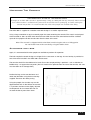


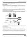


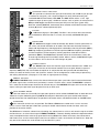

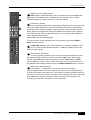


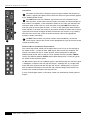
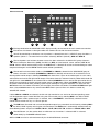
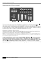


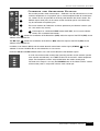
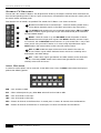


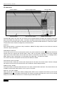
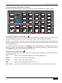
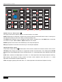

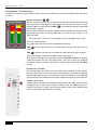


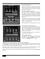
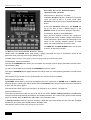
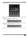


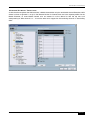
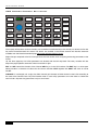


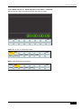
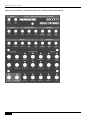

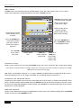


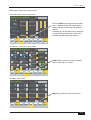


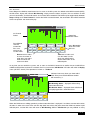


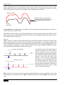


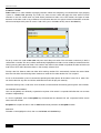


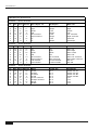


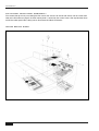

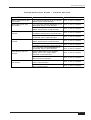


![MX2 sync [final].vp](http://vs1.manualzilla.com/store/data/005975841_1-4533d2555e3004ab9339335fb150c7a8-150x150.png)