1
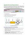
MasterConsole User’s Manual SMX18 SMX28 SMX416 MasterConsole User’s Manual SMX18 SMX28 SMX416 Copyright 1999 Raritan Computer, Inc. Ver. 0E November, 2002 Raritan Computer Inc. Raritan Computer Europe, B.V. Raritan Computer Japan, Inc. Raritan Computer Taiwan, Inc. 400 Cottontail Lane Mient 16c, Kuga Building 7F, 11-6 5F, 121, Lane 235, Pao-Chiao Rd., Somerset, NJ08873 2903 LC Capelle A/D IJssel Kuramae 4-chome Taitoo-Ku Hsin-Tien City, Taipei Hsien USA The Netherlands Tokyo 111-0051, Japan Taiwan Tel: 1-732-764-8886 Tel: 31-10-284-4040 Tel: 81-3-5833-6360 Tel: 886-2-8919-1333 Fax: 1-732-764-8887 Fax: 31-10-284-4049 Fax: 81-3-5833-6336 Fax: 886-2-8919-1338 E-mail: [email protected] E-mail: [email protected] E-mail: [email protected] E-mail: [email protected] Http://www.raritan.com Http://www.raritan.co.jp Http://www.raritan.com Http://www.raritan.com.tw FCC Information This equipment has been tested and found to comply with the limits for a Class A digital device, pursuant to Part 15 of the FCC Rules. These limits are designed to provide reasonable protection against harmful interference in a commercial installation. This equipment generates, uses, and can radiate radio frequency energy and if not installed and used in accordance with the instructions, may cause harmful interference to radio communications. Operation of this equipment in a residential environment may cause harmful interference. Product names mentioned in this document are trademarks or registered trademarks of their respective companies. MasterConsole MX4, MasterConsole II, MasterConsole, and their respective logos are registered trademarks of Raritan Computer, Inc. PS/2, RS/6000, and PC/AT are registered trademarks of International Business Machines Corporation. Mac is a registered trademark of Apple Computer Inc. Sun is a registered trademark of Sun Microsystems. Alpha is a registered trademark of Compaq Corporation. HP9000 is a registered trademark of Hewlett Packard. SGI is a registered trademark of Silicon Graphics, Inc. Japanese Approvals Table of Contents Chapter 1 Getting Started 1 Welcome 1 Introduction 1 Features 1 Quick Installation and test 2 SMX on-screen user interface (OSUI) 3 Chapter 2 Operating The SMX 5 Logging In 5 Selecting a Computer 5 User Customization 8 On-Screen User Interface Functions 10 Chapter 3 Administrator Functions 11 Administration Menu 11 System Configuration 12 User Configuration 14 Channel Configuration 15 Set Second Tier Names 16 Chapter 4 Installing SMX 17 Installations 17 One-Tier Installation 18 Two-Tier Installation 20 Install Base Unit (First-Tier) SMX 20 Connect a SMX unit for second-tier operation: 20 Connect Computers to Second-Tier SMX(s) 21 Channel Configuration for Two-Tier Installation 21 Appendix A: Security Access and Public View 25 Security Access Mode 25 PublicView Video Sharing Options 25 PublicView (P-View) Action 26 Appendix B: Front Panel Controls 27 Front Panel Components and Functions 27 Start Up Display 28 Normal Display 28 Function Selection Screen 28 Set LCD Contrast 29 Set Tier 29 Set Password 30 Disable Password 30 Logout 31 Reset SMX 31 Display Firmware Version 31 Display Serial Number 32 Select Sync Type 32 Appendix C: Glossary 33 Appendix D: Troubleshooting 36 Appendix E: Specifications 37 SMX Models 37 Cable Kits 37 Computer Cable Kits: For connecting computer to SMX 37 User Console Cable: For connecting SMX User Port to User Console 38 Cascading Cable: For connecting SMX second tier to base SMX. 38 Table of Figures Figure 1 OSUI Menu Structure 4 Figure 2 Login Menu 5 Figure 3 Selection Menu 7 Figure 4 Selection Menu by Name 7 Figure 5 User Profile Menu 8 Figure 6 Help Menu 10 Figure 7 Administration Menu 11 Figure 8 System Configuration Menu 12 Figure 9 User Configuration Menu 14 Figure 10 Channel Configuration Menu 15 Figure 11 One-Tier Configuration 17 Figure 12 One-Tier Installation Cabling Details 19 Figure 13 SMX Back Panel 19 Figure 14 Two-Tier Configuration 21 Figure 15 Two-Tier Installation Cabling Details 22 Figure 16 Device Configuration Menu 1 23 Figure 17 Device Configuration Menu 2 23 Figure 18 Device Configuration Menu 3 24 Figure 19 SMX Front Panel 27 Figure 20 SMX Front Panel Buttons 27 Figure 21 LCD Normal Display 28 Figure 22 Set LCD Contrast 29 Figure 23 Set Tier 29 Figure 24 Set Front Panel Password 30 Figure 25 Disable Front Panel Password 30 Figure 26 Log Out 31 Figure 27 Reset SMX 31 Figure 28 Display Firmware Version 31 Figure 29 Display Serial Number 32 1 Chapter 1. Getting Started Welcome Thank you for purchasing Raritan Computer’s MasterConsole SMX. Introduction Raritan's keyboard/video/mouse (KVM) switches are engineered to provide reliable, costeffective, central control of multiple computers. This eliminates the cost and clutter of unnecessary equipment, reclaims space, and improves productivity for a host of applications. SMX is a KVM switch for Sun Microsystems’s Servers and workstations. SMX has three models: SMX18, SMX28, and SMX416. SMX18 allows 1 user to control up to 8 computers. SMX28 allows up to two simultaneous users to select and operate up to 8 computers. SMX416 allows up to four simultaneous users to select and operate up to 16 computers. Exclusively one user can control each computer at a time. Or if desired, the SMX28 and SMX416 can be optionally configured to allow sharing of videos among users. Each user is provided with an On-Screen User Interface (OSUI) menu to facilitate operation. A LCD display on the SMX front panel continuously displays the status of the system, and front panel control buttons allow the systems administrator to perform maintenance functions and define system operation parameters. The firmware program can be upgraded via a built-in communication port from a Windows 95/98 PC. Features • Offering models to connect up to 16 computers and 1 to 4 user consoles • Allowing 2-tier configurations to accommodate up to 256 computers • Locate computers, cascaded units, or user consoles (keyboard, monitor, and mouse) up to 90 feet away from the SMX. • Easy to install tangle proof, double-shielded coaxial cable in lengths of 2, 6.5, 13, 20, and 30 feet • Built in dedicated keyboard and mouse emulators for flawless operation • Includes keep-alive design to ensure non-stop computer operation in case of power loss to the switch • Supports high-resolution video to 1600 x 1280 • Contains a powerful on-screen user interface for simple operation and system management • Supports multiple keyboard language types • Assigns meaningful names to connected computers to select from pop-up, on-screen menus • Stores up to 60 user names, each with personalized operating profile and optional password for security 2 • Contains individual user-controlled functions to AutoSkip inactive channels and to AutoScan computers at variable rates • Engineered with multilevel security to ensure authorized access to each computer by each user • Offers PublicView video sharing features with several options for users to share video with follow along and camp-on actions • Has a front panel LCD display status of user ports • Available on-site firmware upgrades via built-in RJ11 administration port • Add on optional 19” rack mount bracket Quick Installation and test Chapter 4 provides detail installation procedure. For a quick installation and test of SMX, perform the following: 1. Plug the power cord into the SMX and turn the power ON. 2. Observe the LCD display on the front panel as the SMX goes through the power on self-test. When the LCD displays a circulating “Raritan SMX18 [28,416]: Base SMX18 [28,416]” message, the unit is ready. 3. Locate a user console cable, CCSnnF. Plug the DB25 connector to a user port on the back panel of SMX unit. 4. Plug a user console—keyboard and monitor—into the connectors at the other end of the user cable. 5. If keyboard in a language other than English is required perform the following steps prior to proceeding with installation: a) Login as the user <admin> for the administrator. User names are not case sensitive. The administrator’s default password in - raritan - typed in lower case. Passwords are case sensitive. b) Press <F5> to bring up the Administration Menu. c) Select Admin Function number one – System Configuration. d) Press <Tab> (forward) key to move to the KB Language Type. e) Press <Enter> to edit KB Language Type. Highlighed area will turn green. f) Use <!>, or <"> keys to toggle to the desired keyboard language. g) press <Enter> and then <Y> for confirmation to save change. Press <Esc> to exit without saving change. h) All user stations will now require a keyboard that matches the language chosen. 6. Login Menu will now be displayed on the monitor. The keyboard’s <Scroll Lock> LED will be blinking. 7. Enter usera as user name, and press <Enter> to login. A Selection Menu will be displayed on the monitor. 3 8. Unwrap a computer cable, CCSnn. Plug the DB25 connector to a Channel on the back panel of SMX unit. 9. Plug the other end of the cable to a Sun’s keyboard/monitor ports (if you have a 15pin HD15 video port, you can purchase a Raritan adapter, P/N 1396C, to convert the 13W3 female cable plug to an HD15 male plug). 10. Power on the Sun. 11. The Sun channel on the Selection Menu will turn green. 12. Use the <!> and <"> keys to select the green line, and press <Enter>. 13. You will now be able to operate the Sun connected to SMX. Congratulations! This quick test is complete. # 1To go back to the SMX selection menu, press <Scroll Lock> key twice rapidly. This activates the on-screen user interface. The <Scroll Lock> LED on the user console keyboard blinks indicating the on-screen user interface has been activated. SMX on-screen user interface (OSUI) SMX on-screen user interface (OSUI) consists of a simple hierarchy of menus and screens. Each menu (except Login Menu) contains the following sections (Figure 1.): • Title Line • Menu/Screen Body (for text and fields) • Help Messages • Status Line (displays Skip/Scan status, OSUI activator, and P-View indicator if appropriate) Function keys F1, F2, F4, and F5 switch between different first-level menus. # Pressing <F1> while the on-screen user interface is active invokes the Help Screen, which details all options available to the user. # Whenever the on-screen user interface is activated on a user console, that console keyboard’s <Scroll Lock> LED indicator blinks. 1 This symbol, #, provides hints and tips. 4 Figure 1 OSUI Menu Structure 5 Chapter 2. Operating The SMX This section describes how a user operates SMX functions to access Suns. Logging In # You must first login to gain access to the Suns connected to SMX. When the system is first turned on, the Login Menu will be displayed on the monitor of each user console. (Figure 2.) SMX ID is the name of this SMX unit, and User Port is the number (1 through 4 depending on the model) of the physical SMX user port to which this user console is currently connected. Please Login Device ID : Base SMX User Port : 1 User Name : Password : Usera Help Messages Figure 2 Login Menu 1. Enter your user name assigned by the administrator. If user names have not been assigned, the default is usera, userb, userc, or userd for users, admin for the Administrator. User names are not case sensitive. 2. Press <Enter>. If a password is necessary, you will be prompted to enter it, and press <Enter> again. Passwords are case sensitive. (See Changing Password on page 9.) 3. The Selection Menu will be displayed. (Figure 3 & Figure 5) To go to other menus, use the Function keys. (See On-Screen User Interface Functions on page 10.) Selecting a Computer 1. After your successful login to the SMX, the Selection Menu will be displayed. (Figure 3 & Figure 5.) Or, you can activate the on-screen user interface by pressing the <Scroll Lock> twice rapidly, the Selection Menu is displayed as the first menu. 2. The Selection Menu lists channels sorted either by channel ID (Ch. ID) number or alphabetically by Sun name. Default sorting is by channel ID number. Pressing <F12> toggles between sort by channel ID number or by Sun name. 6 3. 4. 5. • The Selection Menu displays up to eight channels. • The Ch. ID column indicates the physical channel to which each computer is connected. • The Name column lists the computer name. • The Stat column shows each channel's security class on the left side of the column, and the channel-specific scan rate—in seconds—on the right side of the column. (See Channel Configuration on page 15 for instructions to change names, security classes and scan rates.) The highlight bar is used to select a channel for connection to the local user console. Each channel’s availability is visually indicated by the following text colors: • Black—no computer connected or computer is powered down. • Green—a channel is active and available. • Red—another user is connected. The highlight bar will skip this channel. • Yellow—unavailable, another user is connected, but the video is available to view. • Purple—connected to another SMX device, rather than a computer. • Cyan—additional path (channel) connected to a second-tier SMX. The highlight bar will skip this channel. • White—current status unknown. # If the security class of a channel is shown in red, the channel cannot be selected due to security restrictions # A small red triangle will point to the name of the computer — if any — which you have currently selected. To select a computer: • Use the <Page Up>, <Page Down>, <!>, and <"> keys to highlight the desired computer and press <Enter>, • When the Selection Menu is sorted by channel ID number, press the desired computer's key number—shown in the left-hand column—and press <Enter>, • When the Selection Menu is sorted by Name—arranged alphabetically — you can type the first character(s) of the desired name to quickly jump to the name that most closely matches the characters you type, and press <Enter>. When you select a computer, you automatically return to normal computer operation at the selected computer—OSUI is turned off. • If you select a second-tier SMX device, you will go to the Selection Menu of that device. To return to the base SMX Selection Menu from any other Selection Menu, press the <Home> key. 7 Figure 3 Selection Menu Selection Menu by Name Page 1/ 1 Name Ch.ID Stat ------------ ------- -----Server-Mail 02 A0 03 Server-Print 06 A0 03 SWS.Bob 03 B0 03 SWS.Jack 04 A0 03 Untitled-001 01 A0 03 Untitled-005 05 A0 03 Untitled-007 07 A0 03 Untitled-008 08 A0 03 ------------ ------- -----Help Messages Status Line Figure 4 Selection Menu by Name 8 User Customization The User Profile screen is for displaying your SMX configuration and to setting/changing your preferred operating parameters. (Figure 5) 1. Activate on-screen user interface by pressing the hot-key <Scroll Lock> key twice rapidly. 2. Press <F4> to access the User Profile screen. • The Connected field displays the name and the channel ID number of the currently selected computer. • The User field displays the User Name entered at login. • The User Port field displays the user port to which you are connected. • The Security field displays your security class. • The Admin field displays your administrator privileges. User Profile Connected: SWS.Bob Ch 3 User: Yee Station: 1 Security: A0 Admin: Yes Scan Mode: Global Global Scan Rate: 03 Seconds ID Display: On 03 Seconds Green Mode: Off 05 Minutes Hotkey: Scroll Lock Display Position: Menu ID Help Mode: Circ Left P-View Switch: Do Nothing Help Messages Status Line Figure 5 User Profile Menu 3. Select the field you want to edit by pressing the <Tab> (forward) <Shift-Tab> (backward) keys to move to the desired field. Press <Enter> to begin the edit. The highlighted area will turn green. When the editing is completed, either press <Enter> to retain the changes, or press <Esc> to cancel them. • Scan Mode: Use the <!> and <"> keys to toggle between Global and Individual. The Global Scan Mode scans each channel for the same amount of time, indicated by the Global Scan Rate. The Individual Scan Mode scans each channel for the specified time as shown in the Selection Menu. The default 9 setting is Global. (Setting the channel’s individual scan rate is an administrative function—see page 16) • Global Scan Rate: Type a number from 01 to 24, or use the <!> and <"> keys to increment or decrement. The default setting is 3 seconds. • ID Display: The ID Display is a small window which shows the computer name and the channel ID number when switching or scanning between channels. It is controlled by two fields: On/Off: Use the <!> and <"> keys to toggle on and off. Time: Type a number from 01 to 24, or use the <!> and <"> keys to increment and decrement. When it is incremented beyond 24, it displays “—“, indicating that ID window will be shown all the time. The default setting is On/03 seconds. • Green Mode: The Green Mode (PowerSave mode) blanks the screen if the user console is idle for the specified amount of time. It is controlled by two fields: On/Off: Use the <!> and <"> keys to toggle on and off. Time: Type a number from 01 to 99, or use the <!> and <"> keys to increment and decrement. The default setting is On/05 minutes. • Hot-key: Use the <!> and <"> keys to select <Scroll Lock>, <Caps Lock>, or <Num Lock>. Press the selected hot-key twice rapidly to activate the on-screen user interface. The default setting is <Scroll Lock>. • Display position: This lets you position the On-Screen menu and ID Display window. Use the <!>, <">, <%> and <&> keys to position the selected window. • Help Mode: Use the <!> and <"> keys to select the preferred help mode. This controls how the help messages are presented on the on-screen user interface menus and screens. The default setting is Circulate Left. • PublicView Action (P-View Action): PublicView enables video sharing between users. The administrator can set the PublicView video sharing option to grant system-wide permission that allows the video of any user to be viewed by any other user. If the administrator permits video sharing, the option is used for setting preferences. Use the <!> and <"> keys to select the preferred mode: “Do Nothing”, “Follow User”, “Connect Sun”, or “Notify”. Please see the Appendix A: Security Access and Public View on page 25 for detail explanations. 4. Changing Password: To add, delete or change your password, press <P>. You will be prompted to enter your new password up to eight characters. Press <Enter> and confirm by re-entering your new password. Then press <Enter> again to retain the change, or press <Esc> to cancel it. 5. Saving Changes: Press <S> to save your changes at any time. When you press <S> or exit the menu, you will be prompted to confirm your changes. 10 On-Screen User Interface Functions Use the following function keys to access SMX OSUI functions: Press... When you want to... <F1> Access Help; get a list of all the Function keys (Figure 6) <F2> Access Selection Menu; view the list of channels, security levels, scan rate, or to select a channel <F4> Access the User Profile; view and change user specific operating parameters <F5> Access the Administration Menu (if you have Administrator Privileges) <F6> Toggle ON/OFF AutoScan <F7> Toggle ON/OFF AutoSkip <F8> Permit/deny PublicView <F9> Logout/login as a new user <Shift-F9> Disconnect from a channel without logging out <F12> While in Selection Menu, toggle sorting by name or channel ID <Esc> Exit # If a user does not have administration privileges, then the F5 function will be displayed in red. # If F8 has no effect with respect to granting PublicView permission based on the view mode setting, it will be displayed in red. Help SMX Version: SMX-p-1.31 Serial Number: CN9C0028 F1 Help / Esc Exit F2 Channel Selection -F12 Sort by Channel/Name F4 User Profile F5 Administrative Functions F6 Toggle Scan On/Off F7 Toggle Skip On/Off F8 Permit/Deny Public View F9 Logout -Shft+F9 Release Channel Help Messages Status Line Figure 6 Help Menu 11 Chapter 3. Administrator Functions This section describes the functions that enable the administrator to configure the SMX system so the user can access the computers connected to the SMX. The functions are performed from a set of administration menus. Administration Menu The Administration Menu is used for setting security classes, maintaining user names and privileges, and managing the system configuration. These tools enable the administrator to control access to the SMX and all connected computer resources. 1. Log into the system as admin or use your user name if you have administrator privileges. The Selection Menu will be displayed. # The default password for the admin is “raritan” and is case sensitive. You should change the default password as soon as possible to prevent any misuse of the system. 2. Press <F5> to access the Administration Menu. The Administration Menu displays user port connections, up to 4 ports depending on the SMX model. (Figure 7.) • User Port Connections: User names of the users logged into each user port. 3. Using the <!> and <"> keys to select the desired submenu and press <Enter>. Administration Menu User Port Connections 1: Yee 2: Jayson 3: None 4: None Choose Admin Function - -------------------------1 System Configuration 2 User Configuration 3 Channel Configuration 4 Set 2nd Tier Names - -------------------------Help Messages Status Line Figure 7 Administration Menu 12 System Configuration The System Configuration menu is used for setting the global parameters that control the operation of the system for all users. (Figure 8.) 1. The System Configuration screen displays the current settings of the parameters. 2. To select the field you want to edit, press the <Tab> (forward) <Shift-Tab> (backward) keys to move to a desired field. Press <Enter> to edit the field. The highlighted area will turn green. When the editing is completed, either press <Enter> to retain the changes, or press <Esc> to cancel them. System Configuration Device ID: Base SMX28 Security Timeout: On Logout 15 Min Access Mode: Free Access P-View Mode: No P-View Admin Silent P-View: Yes Allow Blank Password: No KB Language Type: English Login Blank: Off 05 Minutes Login Help Mode: Multi-Line Automatic Sync Detection Help Messages Status Line Figure 8 System Configuration Menu • SMX ID: This is the name of the SMX.Type in the desired name of the device. This gives the device a unique meaningful name, which is important if you have multiple MasterConsole units. The default names are Base SMX18 [SMX28, SMX416]. If the ID is changed, the new name will be reflected on the LCD after the device is reset or next power up. • Time Out: The amount of time—in minutes—before a user is logged out of the system, if the user is idle for that amount of time. On/Off: Use the <!> and <"> keys to toggle on and off. Time: Type a number from 01 to 99, or use the <!> and <"> keys to increment or decrement the Time Out time in minutes. The default setting is On/5. • Access Mode: Use the <!> and <"> keys to select one of the four Access Modes: Free Access, Exact Match, 2 Digit Level, and Level/Group. The default is Free Access. (See Appendix A: Securuity Access and Public View on page 25 for detailed explanations of security modes.) 13 # The security classes for individual users and channels must be set in the User Configuration Menu and the Channel Configuration Menu of the administration menus. • P-View (PublicView) Mode: Use the <!> and <"> keys to select “No V-share”, “Always On”, “Admin Only”, “User Permit”, “Admin or UP”. The default is “No Vshare”. (See Appendix A: Security Access and Public View on page 25 for detailed explanations of video sharing modes.) • Admin Silent P-View: When video sharing is permitted, the user is notified if another user is sharing the video. If you have administrator privileges, this option allows you to turn off the message. Use the <!> and <"> keys to toggle Yes or No. • Allow Blank Password: Use the <!> and <"> keys to toggle Yes or No. This field controls whether a user can specify a blank password. The default setting is No. # If this field is set to No, a user may not set a blank password. However, a newly created user has by default no password unless the user or the administrator sets one. • K/B Language Type: If a keyboard in a language other than English is required Press <Enter> after tabbing to this field to edit KB Language Type. Highlighed area will turn green. Use <!>, or <"> keys to toggle to the desired keyboard language. Press <Enter> and then <Y> for confirmation to save change. Press <Esc> to exit without saving change. All user stations will now require a keyboard that matches the language chosen. • Login Blank: The Login Blank feature will blank the Login screen after the user console is idle for the specified amount of time in minutes. This acts as a screen saver to protect the monitor. When the screen is blanked, press any key to bring back the Login Screen. These fields are edited the same way as Security Timeout. The default setting is On/5 minutes. • Login Help Mode: Use the <!> and <"> keys to select the desired help mode. This will control how the help and welcome messages are presented on the Login screen. The default setting is Multi-Line. • Automatic Sync Detection: Certain SMX units have this automatic sync detection feature built-in. On SMX units that do not feature automatic sync detection, the System Configuration menu will have an option to allow you to manually set the sync type to accommodate certain types of monitors. If you experience abnormality in the On-Screen Display, set the appropriate (or all) user port(s) to Y. The default is N. (See also Select Sync Type in Appendix B: Front Panel Controls.) 14 User Configuration The User Configuration Menu allows the system administrator to add, delete, and edit the user names and security rights. (Figure 9) It also displays current connection status for each user. 1. Use the <!>, <">, <%>, <&>, <Tab>, <Shift-Tab>, <Page up>, <Page down>, <Home>, and <End> keys to move within the menu. Press <Enter> to edit the field. The highlighted area will turn green. When the editing is completed, either press <Enter> to retain the changes, or press <Esc> to cancel them. User Configuration User: John Page 1/ 1 Name SC Adm Connection -------- -- --- ------------Admin A0 Yes None Jayson A0 No None Usera A0 No None Userb A0 No None Userc A0 No None Userd A0 No None John A0 Yes SWS.Bob -------- -- --- ------------Help Messages Status Line Figure 9 User Configuration Menu 2. This menu displays user information, one user per line. • User: This field displays the login user name. • Name: The Name column displays and allows editing of system user names. The user names are not case sensitive. Type up to 8 characters to change a name. # The special user name Admin cannot be changed. • SC: The SC column displays the security class of the user. Typing A-P will change the user’s security level; typing 0-9 will change the user’s security group. The default value of a newly created user is A0. (See Appendix A for more details about security classes.) • Adm: The Adm column indicates whether the user has administration privileges. Use the <!> and <">keys to toggle Yes or No. The default setting is No. • Connection: The Connection column shows the status of each user and displays the channels to which they are presently connected. 3. Adding a new user: To add a new user, press <C>. A new default user name will be added. Proceed to edit the default name to a user name desired. 15 4. Deleting a user: Move the highlight bar to a user line, press <D>. The highlighted user will be removed from the system. 5. Logging out a user: Move the highlight bar to a user line, press <L>. The highlighted user will be logged out from the system. Channel Configuration The Channel Configuration Menu allows the system administrator to edit the computer names, security classes, and individual scan rates associated with each channel. (Figure 10) Any device—such as computer or any MasterConsole unit - can be connected to SMX channels. To create a two-tier installation, SMX units are “cascaded” from one or more of the base SMX channels. (See page 20 for two-tier installation.) PLEASE NOTE—This section describes the channel configuration for a stand alone SMX. Figure 10 Channel Configuration Menu 1. Use the <!>, <">, <%>, <&>, <Tab>, <Shift-Tab>, <Page up>, <Page down>, <Home>, and <End> keys to move within the menu. Press <Enter> to edit the field. The highlighted area will turn green. When the editing is completed, either press <Enter> to retain the changes or press <Esc> to cancel them. 2. This menu displays channel information, one computer per line. • MC: The name of this SMX—Same as SMX ID. • Ch. ID: This column displays the physical Channel ID number to which the device connects to SMX. • Name: This column displays and allows editing of the computer names. Computer names are case sensitive and may be up to 12 characters. 16 • Sec: This column displays the security class of the computer. Typing A-P changes the computer’s security level; typing 0-9 changes the computer’s security group. The default value of a computer is A0. (See Appendix A for detailed explanations of security modes.) • Scn: This column displays the computer’s individual scan rate. Type a number from 01 to 24, or use the <!> and <"> keys to increment or decrement the Scan Rate. The default setting is 3 seconds. Set Second Tier Names This selection enables you to change the name displayed on the LCD of the second tier SMX units. When this option is selected, the base SMX will communicate with all secondtier SMX units and update their names. A confirmation message – Names set on tiered units – will appear. (See page for two-tier installation.) If no tier names have been entered, all tiered unit’s LCD’s will continue to display the SMX default tier name. 17 Chapter 4. Installing SMX Installations MasterConsole SMX can be installed to control 8 or 16 computers in a one-tier installation with up to 4 simultaneous users depending on the SMX models. ’ 2 0 6 to ’ C S E ’ 2 6 to C N U F T N E ’0 X M S 2 8 2 ’to ’ 0 6 C N U F C S E 2 ’to T N E 6 ’ 0 X 8 M S 2 Figure 11 One-Tier Configuration 18 One-Tier Installation In a one-tier installation, only Sun computers are connected to a single SMX unit (Figure 15). Complete the following steps for a one-tier installation: 1. Shut down and power off all computers to be connected to the SMX. 2. Install a user console to SMX. • Plug the 25-pin connector of a user console cable (CCSnnF) into one of the user ports on the SMX back panel. (Figure 16 & Figure 18) • Plug a user console (Sun keyboard, Sun monitor, and Sun mouse) into the connectors at the other end of the CCSnnF user cable. 3. Power on the SMX unit. • SMX will go through the start up test. (See Start Up Display on page 28) 4. If keyboard in a language other than English is required perform the following steps prior to proceeding with installation: a) Login as the user <admin> for the administrator. User names are not case sensitive. The administrator’s default password in - raritan - typed in lower case. Passwords are case sensitive. b) Press <F5> to bring up the Administration Menu. c) Select Admin Function number one – System Configuration. d) Press <Tab> (forward) key to move to the KB Language Type. e) Press <Enter> to edit KB Language Type. Highlighed area will turn green. f) Use <!>, or <"> keys to toggle to the desired keyboard language. g) Press <Enter> and then <Y> for confirmation to save change. Press <Esc> to exit without saving change. h) All user stations will now require a keyboard that matches the language chosen. 5. Login Menu will now be displayed on the monitor. The keyboard’s <Scroll Lock> LED will be blinking. • Enter usera in the user name field of Login Menu, and press <Enter>. The Selection Menu will be displayed. (See page 7) 6. Connecting a computer to SMX • Using a Sun Computer Cable Kit (CCSnn), plug the 25-pin connector into one of the numbered channel ports on the SMX back panel. • Plug the cable's two (2) other connectors into the computer's keyboard and monitor ports ((if you have a 15-pin HD15 video port, you can purchase a Raritan adapter, P/N 1396C, to convert the 13W3 female cable plug to an HD15 male plug). • Power on the connected computer. 19 • On the Selection Menu, the line displaying the channel to which the new computer has been connected will turn green. • Using the <!> and <"> keys, select an active channel and press <Enter>. • You will now be able to operate the computer just as if the keyboard, monitor, and mouse were connected directly. 7. Repeat steps 2 and 6 to connect the remaining user console and computers to the SMX. 2 4 6 8 3 5 7 0 6 C A /5 H 0 1 IN .5 2 /3 z1 /0 A .5 1 V C Figure 12 One-Tier Installation Cabling Details U erPs rtso 1 Ch na elPo rts Figure 13 SMX Back Panel 20 Two-Tier Installation In a two-tier installation, all units must be MasterConsole SMX models. (Figure 20 & Figure 22). Special Note For Two-Tier Configurations: If a keyboard language other than English is required, then all SMX units in your configuration – whether a base SMX unit or a second tier SMX unit – must be configured by following all of step #4 on page 17 prior to being connected. Install Base Unit (First-Tier) SMX Follow the One-Tier installation procedure with the exceptions noted on the next page: Note: If a keyboard in a language other than English is required, remember all of step #4 on page 17 must be performed on this base SMX unit • Reserve up to 4 consecutive base unit channels for each SMX unit you will cascade as a second-tier unit. The number of channels reserved depends on the number of user ports you have on the second-tier unit and number of paths you desire to have from the base tier unit to the second-tier unit. For example, if you have a SMX28 as a second-tier unit, you should reserve 2 channels on the base tier unit. • Power off the base SMX unit and then begin the procedure to connect second-tier SMX(s) to the base unit as described below. # If computers have already been connected to the base SMX unit, you do not have to shut down the computers, even when powered off, the SMX’s keyboard/mouse keepalive feature continues performing keyboard/mouse emulation on all attached Sun computers. Connect a SMX unit for second-tier operation: Special Note For Second-Tier SMX Units: If a keyboard language other than English is required, then each second-tier SMX unit in your configuration must be configured by following all of step #4 on page 17, prior to being connected to the base SMX unit. Power off all SMX units before connecting them to the base SMX. Follow the procedures below to install the second-tier SMX. Next, perform the appropriate channel configuration from the Administration Menu, described in the next section. (page 20) It is recommended that channel configuration be performed incrementally after each second-tier installation. 1. Using a cascading cable (CCPnnE), plug the DB25 connector (female) into one of the user ports of the second-tier SMX. 2. Plug the cable’s other DB25 connector (male) into the first channel you reserved on the base SMX back panel. 3. Repeat Steps 1 and 2 to connect the remaining user ports to the channels reserved on the base SMX. 4. Power on the second-tier SMX. 21 5. From the front panel, follow the Set Tier procedure (page 29) to set the tiered user ports to second-tier status as indicated by a ”T” on the front panel LCD display. 6. Power on the base SMX units, and perform channel configuration from the Administration Menu, described in Channel Configuration for Two-Tier Installation. (page 21) # To guarantee correct operation, always power on the second-tier SMX before the base unit. 4 S E C N U F SM X 4 S E C N U F T N E X SM Figure 14 Two-Tier Configuration Connect Computers to Second-Tier SMX(s) Follow Step 6 of the SMX One-Tier Installation procedure detailed in the previous section on page 18. Channel Configuration for Two-Tier Installation After installing a second-tier SMX to a base SMX, you must perform Channel Configuration with the Administration Menu to re-configure the base SMX. As explained in the Administration Menu section (page 11), you must login with administration privileges to access the administrator functions described below. 1. Press F5 to access the Administration Menu. 22 2. Select the Channel Configuration sub menu, press <ENTER>. The Channel Configuration menu is displayed listing channel ID and channel names. (Figure 10) 3. Use the <!> and <"> keys to highlight the first channel you have reserved for the second-tier SMX during the base SMX installation process. # Up to four consecutive channels can be connected to a second-tier SMX device. When a channel is selected for a second-tier SMX, up to 4 paths will be presented for selection. However, if any other SMX device is on any one of the 4 subsequent channels, it will limit the number of paths available. 4. Press <C> to bring up the Device Configuration screen. (Figure 16) 5. From the list of devices, select line 1 for SMX device and press <ENTER>. A next level of the Device Configuration menu will be displayed. (Figure 17) 6. From the menu, select the number of channels that match your second-tier SMX unit and press <ENTER>. The next menu displayed is to select the number of paths you desire. (Figure 18) Figure 15 Two-Tier Installation Cabling Details 23 Device Configuration Name: Untitled-001 Type: SUN Connections: 1 Channels: -Base: Base SMX28 Ch.ID: 01 Device Abv - ---------------------- --1 MasterConsole SMX SMX 2 Sun/No Device SUN - ---------------------- --- Current Device Settings Help Messages Status Line Figure 16 Device Configuration Menu 1 Device Configuration Name: Untitled-001 Type: Sun Connections: 1 Channels: -Base: Base SMX416 Ch.ID: 01 Number of Device Channels - -------------------------1 8 Channels 2 16 Channels 3 32 Channels - -------------------------- Current Device Settings Help Messages Status Line Figure 17 Device Configuration Menu 2 7. From the list of paths available, select the number of paths desired and press <ENTER>. 8. The display will return to the Channel Configuration menu. (Figure 10) 9. Press <F2> and confirm that the new SMX device is displayed in purple on the proper channel in the Selection Menu. (Figure 3) 10. Select the new SMX device and press <ENTER>. 11. The Selection Menu of the new second-tier device should be displayed. 24 12. You have now configured a second-tier device to a base SMX. Go back to the Channel Configuration Menu to rename your second tier computers by pressing F5. (Figure 10) 13. Select option number 3—Channel Configuration. 14. Using the <!> and <"> keys, highlight the second tier device you want edit. 15. Press the G key—on the keyboard—to select this device for channel editing. 16. Edit the name(s) of the computers on the second tier. 17. Enter S to save edit or <esc> to cancel it. 18. Enter Y to save menu or N to re-edit. Device Configuration Name: Untitled-001 Type: Sun Connections: 1 Channels: -Base: Base SMX416 Ch.ID: 01 Number of User Connections - -------------------------1 1 Path 2 2 Paths 3 3 Paths 4 4 Paths - -------------------------- Current Device Settings Help Messages Status Line Figure 18 Device Configuration Menu 3 25 Appendix A: Security Access and Public View Security Access Mode SMX provides administrators with four modes of security access in addition to the login security. Depending on your business and security needs, choose the option best suited to manage your system. # (Caution!) Users with admin privileges will always be able to access any computers regardless of the mode. 1. Free Access: All users have free access to all channels. The only security is the login user name and password—if used. Setting security classes has no effect when this mode is invoked. Free Access is the default setting. 2. Exact Match: The user’s security class must be exactly the same as the channel security class in order for the user to access that channel. • Example: If both the user class and a channel class were B1, then the user could access that channel; if the user class were any other security class, access would not be allowed in Exact Match security mode. 3. 2 Digit Level: The user security class must be higher or equal to the channel security class in order to gain access. A0 is highest; P9 is lowest. • Example: A user of security class of C2 could access all channels with a security class of C2 or lower, but could not access any channels of security class C1 or higher. 4. Level/Group: Access to a channel is determined by the following rules: • If the letter level of the user is higher than the letter level of the channel, access is allowed; if the level of the user is lower than the level of the channel, access is denied. • if the levels are equal, then the group—number—determines access: • Group 0 is the universal group: if either the user group or the channel group is 0, access is allowed. • Otherwise, the channel group must match the user group in order to gain access. PublicView Video Sharing Options Users of the SMX have exclusive control to the computer selected. However, depending on your business needs, the administrator can configured the SMX PublicView feature to allow users to view the video of a computer controlled by another user. There are 5 PublicView options: 1. No PublicView: No video sharing—system default. 2. Always On: All users are permitted to view the video of computers being used by other users. 3. Admin Only: Only the users with administrative privileges are permitted to view the video of computers being used by other users. 26 4. User Permit: User is permitted to view the video of another computer if the user currently in control of that computer has granted permission to do so. 5. Admin or UP (User Permit): This is a combination of 3 and 4. PublicView (P-View) Action When a user is viewing the video of a connected user, there are 4 optional actions that can be executed when the connected user switches. The viewing user selects the action from the User Profile Menu. The actions are: • Do Nothing: Continue viewing the video of the same computer. • Follow User: Follow the connected user and continue viewing the video of newly selected computer. • Connect PC: Take control—become the connected user—of the computer that the original connected user has switched away from—unless access is denied due to specific user security. • Notify: Do nothing but display a message when the connected user has switched. 27 Appendix B: Front Panel Controls The front panel of the MasterConsole SMX consists of a LCD and 7 buttons. (Figure 19 and Figure 20) The front panel controls provide special systems management and technical support functions. Normally, there is no need to use the front panel beyond viewing status. Typically, the front panel is used for the following tasks: Figure 19 SMX Front Panel 1. Confirming power-on. 2. Programming an SMX unit for second-tier operation. 3. Review Unit’s serial number and firmware version. 4. Some other miscellaneous functions. Figure 20 SMX Front Panel Buttons Front Panel Components and Functions • The LCD (A) shows the status of the system and indicates the functions that can be selected using the front panel control buttons. • The ESC button (B) is used for canceling the displayed function and returning the system to the normal state. • The FUNC button (C) allows the operator to access various functions. • The !, ", % and & buttons (D) (E) (F) (G) are used for selecting or setting various options depending on the function being performed. • The ENT button (H) is used for confirming and executing the selected function. 28 Start Up Display When the SMX is turned on, it performs a start up test. It checks each channel and user port to detect connections. If an error is detected, it will display “ERROR!”, and stop the process. • Press ENT to continue checking the remaining channels and ports. • Recycle the power by turning the SMX off and on to clear the error conditions. • If error persists, power down all computers and devices and then recycle the power again. • If error condition still persists, contact Raritan Technical Support for further assistance. Normal Display After the start-up test, the LCD panel will display a circulating message, “Raritan SMX18 [28, 416]: Base SMX”, on the first line and the user port status on the second line. (Figure 21.) The user port line displays a scrolling status of all user ports, one per second. The first 3 positions of the display denote the Scan/Skip/Tier status—S, K, or T—or a dot if these options are not active. The user’s active channel—Ch #—1 - 16—is displayed after the user port number. Raritan SMX416: ... User 1 Ch 2 Figure 21 LCD Normal Display • First position: S—the user port is in AutoScan mode. • Second position: K—the user port is in AutoSkip mode. • Third position: T—the user port is configured to connect to another SMX—tier. • A dot appearing in any of these 3 positions indicates the option is not activated. Function Selection Screen Nine functions can be performed from the front panel control: Set LCD Contrast, Set Tier, Set Password, Disable Password, Logout, Reset SMX, Display firmware version, Display serial number and Select Sync Type. The following sections describe these functions. To select a function: 1. Press FUNC to enter the Function selection mode. 2. Use ! and " buttons to scroll through the Function List. 3. Press ENT to select the displayed function. Follow the sections below to perform the selected function. 4. Press ESC at any time to return to the Normal Display. 29 Set LCD Contrast The Set LCD Contrast function modifies the contrast level of the front panel LCD display. (Figure 22) To modify the LCD contrast: 1. Press the ! and "buttons to increase and decrease the contrast. 2. Press ESC to return to the normal display. # The LCD contrast can also be adjusted by holding % button and pressing the ! and " buttons any time during normal display. Please ignore the “Select Channel” display. Figure 22 Set LCD Contrast Function Menu Set LCD Contrast Set Tier The Set Tier function should only be used on second-tier SMX units. Be sure to carefully review the Two-Tier Installation on page 20 before proceeding with the Set Tier function. (Figure 23) Function Menu Set Tier Figure 23 Set Tier The Set Tier function programs the user ports of a second-tier SMX to properly perform as a second-tier device. Each of the user ports on a second-tier SMX unit must be programmed as follows. To set a second-tier user port to connect to a Base SMX: 1. Press the ! and " buttons to select the user port number you wish set to second-tier status. 2. Press the % button to toggle the tier indicator—denoted by T—on and off. 3. Press ENT to confirm the selected settings, or, 4. Press ESC to return to the Normal Display and retain the previous setting. 30 Set Password The Set Password function allows the Administrator to password protect access to front panel functions. (Figure 24) A valid front panel password consists of a sequence of exactly six button presses, which must be repeated exactly to gain access. Function Menu Set Password Figure 24 Set Front Panel Password To set the password for the front panel: 1. When prompted, enter a sequence of any 6 front panel buttons except ESC. The second line of the LCD display will show an asterisk (*) for each button pressed. # Pressing ESC before finishing the 6 button presses exits this function without setting a front panel password. 2. The LCD display will prompt you to enter the button sequence a second time for confirmation. Entering the new 6 button password confirms it. 3. Press ESC to return to the Normal Display. # If the front panel is password protected, you must enter your password to access any of the front panel functions. Disable Password The Disable Password function disables the front panel password and allows unrestricted access to front panel functions (Figure 25). Function Menu Disable Password Figure 25 Disable Front Panel Password 1. When this function is selected, the LCD confirms that the password has been deactivated. 2. Press ESC to return to the Normal Display. 31 Logout If a front panel password has been established, the Logout function will exit the current front panel operation and return to password protected (Figure 26). A password is needed to gain control of the front panel functions. 1. When this function is selected, the LCD display will confirm the logout by showing Bye Now! on the second line. 2. Press ESC to return to the Normal Display. Function Menu Logout Figure 26 Log Out Reset SMX The Reset SMX function (Figure 27). lets you restart the SMX unit as if you had physically turned the unit’s power off and back on again. However, SMX will not perform the start-up test unless you hold down the ENT button during restart. Function Menu Reset SMX Figure 27 Reset SMX Display Firmware Version Display firmware version function allows you to review the firmware release level of your SMX unit (When this function is selected, the LCD will display the unit’s firmware release level.) 1. Press ESC to return to the Normal Display. (Figure 36) 2. When this function is selected, the LCD will display the unit’s firmware release level. 3. Press ESC to return to the Normal Display. Function Menu DSP Firmware Vsn Figure 28 Display Firmware Version 32 Display Serial Number Display serial number function allows you to review the serial number of your SMX unit (Figure 29). 1. When this function is selected, the LCD will display the unit’s serial number 2. Press ESC to return to the Normal Display. Function Menu DSP Firmware Vsn Figure 29 Display Serial Number Select Sync Type This function is disabled on models with Automatic Sync Detection. (See Automatic Sync Detection on page 12.) The Select Sync Type function enables the SMX to accommodate as many types of VGA monitors as possible, as some monitors function erratically without continuous synchronization. The SMX can generate either continuous sync signal or regular sync signal. If a user console monitor exhibits abnormal behavior, try changing this setting for the user port to which it is connections Perfrom steps 1-3 of Function Selection first. To control the sync type generated from a user port: 1. Press the ! or " buttons to select the user port number. 2. Press the # button to toggle the sync type between regular and continuous. 3. Press ENT to confirm the selected setting, or 4. Press ESC to return to the Normal Display and retain the previous setting. Versions of SMX that have the Auto Detect Sync function built-in will disable this front panel function. 33 Appendix C: Glossary Administration Menu For installing and configuring access to SMX. Use is restricted to those with Administrator Privileges. AutoScan When activated, SMX automatically cycles through channels, displaying each computer's video for a specified time interval. AutoSkip When activated, channel selection is restricted to active channels. Base Unit The SMX unit to which computers and/or other SMX units are connected in a two-tier configuration. Channel The 25-pin connector where a device is connected to SMX. There are 8 channels on Model SMX units. Active A channel is active when a connected device is powered on. Inactive A channel is inactive when no device is connected to it, or if the connected device is powered off. Channel Configuration Menu For editing computer and device names, changing security classes, and assigning channel-specific scan rates. Channel ID Number The specific channel number to which a device is connected. Computer Name A label of up to 12 characters assigned by an administrator for a device connected to a SMX channel. Configuration One-Tier Only computers are connected directly to a single SMX unit Two-Tier A mix of devices—computers and SMX units—are connected to a base SMX unit. Device A computer or any SMX unit is connected to a base SMX channel. Function Selection Screen Used to access front panel control functions. Green Mode A field in the User Profile Menu used to toggle the PowerSave feature on and off. Hot-key <ScrollLock> For activating on-screen user interface. To activate on-screen user interface, press the hot-key—default twice rapidly. ID Display A single-line display shown on the monitor to identify the currently selected channel. Key Number Located in the left-hand column of the Selection Menu. To quickly select a channel, press the corresponding Key Number on the keyboard when the Selection Menu is displayed. LCD Display Liquid-crystal display screens on the SMX front panel for displaying statuses and controlling administrative functions. Logging In Entering a User Name to gain access to the SMX system. 34 Login Screen For logging into the system as a user or administrator. Logout Disconnects a user from the system. Menu A SMX on-screen user interface display. Menu F Keys Function keys used for accessing on-screen user interface menus. Normal Display Displayed on the LCD and showing the on going status of the SMX. Password Used in conjunction with User Name to gain access to the SMX. PowerSave Allows a properly equipped monitor to operate in energy save mode. See also Green Mode. PublicView To view the video of a computer that is being selected and operated by another user. Reserved Channels In a two-tier configuration, the channels on the base SMX unit allocated to connect second-tier SMX(s). Scan On-screen user interface function used to activate AutoScan. Scan Mode Field in the User Profile; can be set to either Global or Individual. See also Scan Rate. Scan Rate The time interval—in seconds—that a channel's computer is to remain displayed on the monitor when AutoScan is activated. Global Scan Rate: The scan rate used for all channels when the Scan Mode field in the User Profile is set to Global. Channel-Specific (Individual) Scan Rate Scan rate specified for each channel when the Scan Mode field in the User Profile is set to Individual. Channel-specific scan rates are set in the Channel Configuration submenu of the Administration Menu. Security Code Letter/number set assigned to each user and computer to establish user- access rights. Class Refers to the entire security code Level Refers to the letter in the security code Group Refers to the number in the security code Selection Menu For selecting a computer or device. Set LCD Contrast Screen For adjusting the contrast of the LCD on the SMX front panel. Set Password Screen Enables the administrator to password protect the functions on the LCD. Set Tier Screen For connecting second-tier user ports to first-tier channels. Sorting Order of the channels listed in Selection Menu—either by channel ID or by name. Pressing F12 toggles the sort criterion when a Selection Menu is displayed. 35 Start-Up Display Displayed on the LCD when the SMX is turned on—the system checks for the status of computers and user connections. After this start up test, it goes to normal display. System Configuration For allowing and disallowing blank passwords, turning Time Out on and off, changing the Time Out interval, turn the Login Screen on and off, and changing the Login interval. Time Out Length of time that a user port can remain idle—since the last keyboard, mouse, or front panel operation—before the connected console is automatically logged out. User must enter an authorized user name to re-establish access after Time Out. User Configuration Used by the Administrator for adding, deleting, and changing user names, security codes, and administrator privileges. User Console The Sun keyboard, monitor, and mouse plugged into a user port on the SMX back panel. User Name Name a users types to log in to the system. User Port The 25-pin connector by which a user console—Sun keyboard, monitor, and mouse—is connected to SMX. User Profile For setting and changing user passwords and preferences. 36 Appendix D: Troubleshooting a. Check power cord. b. Make sure power switch is turned ON. c. Check cable connection from computer to SMX. d. SMX power supply has built-in surge protection. If you can not regain power during a power recycling process, power off the unit. Wait for 15-20 seconds, then turn on again. No video display for one or all computers. a. Check video cable's connection to the computer. b. Check the monitor and computer. Turn off power to SMX and the computers. Connect the monitor to the computer directly, boot the computer, and make sure the monitor has the proper display. If it does not, the problem is either with your computer, or the monitor is not compatible with your computer. If it does display, continue to Troubleshooting #3. 3. The monitor cannot correctly display the video output from some of the computers. a. The monitor probably does not match the video outputs. If the monitor is a single mode type monitor, all computers must have the same type of video output. 4. After a period of trouble-free a. operation, the keyboard attached to SMX locks (unable to input keystrokes) when a particular computer is selected, but works normally when other computers are selected. The most likely cause of the problem is either a voltage "spike" (increase) or a "brown out" (decrease) in the power supply, which would cause the microprocessors in SMX to malfunction. A short-term solution to the problem is to try to recover operation by turning SMX's power switch off and on. Then, if necessary, restart all computers. The long-term method of avoiding this problem is to power SMX from a UPS. 1. 2. No power. b. Check keyboard connection. 37 Appendix E: Specifications SMX Models Model SMX18 SMX28 1-user, 8-channel model 2-user, 8-channel model Dimensions 17.0"(W) x 10.5"(D) x 1.75"(H) 17.0"(W) x 10.5"(D) x 1.75"(H) Weight 2.8 kg (6.1 lbs.) 2.8 kg (6.1 lbs.) Power 115V/230V Auto Sensing 115V/230V Auto Sensing 50/60Hz, 0.2A/0.1A 50/60Hz, 0.2A/0.1A 0-50°C (32-122°F) 0-50°C (32-122°F) Operating Temperature Model SMX416 4-user, 16-channel model Dimensions 17.0"(W) x 10.5"(D) x 3.5"(H) Weight 3.8 kg (8.4 lbs.) Power 115V/230V Auto Sensing 50/60Hz, 0.2A/0.1A Operating Temperature 0-50°C (32-122°F) Cable Kits Computer Cable Kits: For connecting computer to SMX Part No. Length Connectors CCS06 2' (0.6 M) DB25(M) to 13W3(M), 1 mini-DIN8(M) CCS20 6.5' (2 M) DB25(M) to 13W3(M), 1 mini-DIN8(M) CCS40 13' (3 M) DB25(M) to 13W3(M), 1 mini-DIN8(M) CCS60 20' (6 M) DB25(M) to 13W3(M), 1 mini-DIN8(M) CCS90 30' (9 M) DB25(M) to 13W3(M), 1 mini-DIN8(M) 38 User Console Cable: For connecting SMX User Port to User Console Part No. Length Connectors CCS06F 2' (0.6 M) DB25(F) to 13W3(F), 1 mini-DIN8(F) CCS20F 6.5' (2 M) DB25(F) to 13W3(F), 1 mini-DIN8(F) CCS40F 13' (3 M) DB25(F) to 13W3(F), 1 mini-DIN8(F) CCS60F 20' (6 M) DB25(F) to 13W3(F), 1 mini-DIN8(F) CCS90F 30' (9 M) DB25(F) to 13W3(F), 1 mini-DIN8(F) Cascading Cable: For connecting SMX second tier to base SMX. Part No. Length Connectors CCP10E 3' (1 M) DB25(F) to DB25(M) CCP20E 6.5' (2 M) DB25(F) to DB25(M) CCP40E 13' (3 M) DB25(F) to DB25(M) CCP60E 20' (6 M) DB25(F) to DB25(M) CCP90E 30' (9 M) DB25(F) to DB25(M)