1
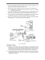
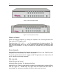
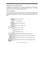
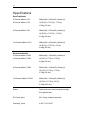
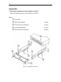
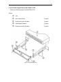
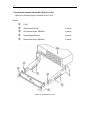
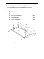
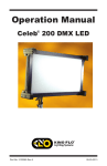
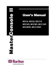
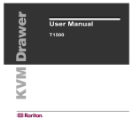
CompuSwitch
User’s Manual
CS2(R)
CS4(R)
CS8(R)
CS16(R)
CompuSwitch
User’s Manual
CS2(R)
CS4(R)
CS8(R)
CS16(R)
Copyright ©1999
Raritan Computer , Inc.
CS16-0D-E, JUNE, 2001
Raritan Computer Inc.
400 Cottontail Lane
Somerset, NJ08873
USA
Tel: 1-732-764-8886
Fax: 1-732-764-8887
E-mail: [email protected]
Raritan Computer Europe, B.V.
Eglantierbaan 16
2908 LV Capelle aan den IJssel
The Netherlands
Tel: 31-10-284-4053
Fax: 31-10-284-4049
E-mail: [email protected]
Raritan Computer Japan, Inc.
Kuga Building 7F, 11-6
Kuramae 4-chome Taitoo-Ku
Tokyo 111-0051, Japan
Tel: 81-3-5833-6360
Fax: 81-3-5833-6336
E-mail: [email protected]
Raritan Computer Taiwan, Inc.
5F, 121, Lane 235, Pao-Chiao Rd.,
Hsin-Tien City, Taipei Hsien
Taiwan
Tel: 886-2-8919-1333
Fax: 886-2-8919-1338
E-mail: [email protected]
Http://www.raritan.com
Http://www.raritan.com
Http://www.raritan.co.jp
Http://www.raritan.com.tw
FCC Information
This equipment has been tested and found to comply with the limits a Class B {for
CS2(R), CS4(R)}, and a Class A {for CS8(R), CS16(R)}, pursuant to Part 15 of the FCC
Rules. These limits are designed to provide reasonable protection against harmful
interference in a commercial installation. This equipment generates, uses and can
radiate radio frequency energy and, if not installed and used in accordance with the
instructions, may cause harmful interference to radio communications. Operation of this
equipment in a residential environment may cause harmful interference.
Product names mentioned in this document are trademarks or registered
trademarks of their respective companies. PS/2, PC/AT, and IBM are
registered trademarks of the International Business Machines Corporation.
Table Of Contents
Introduction
1
Features
1
Installation
1
Operation
4
Troubleshooting
9
Specifications
10
Cables
11
Accessories
11
Appendix
12
1
Introduction
CompuSwitch enables the efficient control of multiple computers, any combination of
PC/ATs, and PS/2s from only one keyboard, monitor, and mouse. The 16-channel model
connects and controls up to 16 computers. The 8-channel model connects and controls
up to 8 computers. The 4-channel model connects and controls up to 4 computers. The
2-channel model connects and controls 2 computers.
Features
∗
∗
∗
∗
∗
∗
Dedicated keyboard and mouse emulators to ensure automatic booting and proper
operation of each computer.
VGA, SVGA, and XGA video support.
SCAN function to automatically cycle through all channels at a selectable scan rate
from 1 to 16 seconds by using push buttons on the front panel and from 1 to 99
seconds by using Hot Key command.
SKIP function to automatically bypass channels without a powered computer
connected.
Simple operation either from the CompuSwitch front panel or from the keyboard
using Hot Key commands.
One-year warranty.
Installation
Start with one computer. Once proper operation is confirmed, additional computers may
be connected.
Procedure
1.
Plug the monitor, keyboard, and PS/2 mouse into the ports marked VGA monitor,
PS/2 or AT keyboard, and PS/2 mouse on the CompuSwitch back panel (figure 1, 2,
3, 4).
Caution: Make sure that all computers are powered OFF before they are connected
to CompuSwitch.
2
Figure 1. Back panel - CS2
Figure 2. Back panel - CS4
Figure 3. Back panel - CS8
Figure 4. Back panel - CS16
3
2.
Using the appropriate CompuSwitch cable, connect the 25-pin connector to any
channel on the CompuSwitch back panel (figure 5).
3.
Plug the cable’s video, keyboard, and mouse connectors into the computer ports.
Note: CompuSwitch is automatically powered when at least one connected
computer is powered ON.
4.
Power ON the computer. On the CompuSwitch front panel, the light above the Skip
button will be ON, and the light above the connected channel button will be ON.
5.
The video from the connected computer will be displayed on the monitor. Operate
the keyboard and mouse as if they were connected directly to the computer.
6.
After you have verified operation of one computer, connect the remaining computers
following steps 2–4. You may now begin using CompuSwitch.
Figure 5. Cabling details
Installation Notes
1. Connections are provided for either a 6-pin PS/2-style or a 5-pin Extended AT-style
keyboard. Do not connect both keyboards simultaneously. Because the Hot Key
Mode operation (page 9) requires full PS/2 keyboard functions, a PS/2-style or an
Extended AT-style keyboard, which supports these functions, is recommended.
2. You may simultaneously connect PS/2 and AT computers to CompuSwitch with the
appropriate cables. However, only a PS/2 mouse can be used with CompuSwitch
to operate the computers.
4
Operation
Operate CompuSwitch from the front panel, or directly from the keyboard using Hot Key
commands. Either way, lights on the front panel indicate the status of operation.
Note: Numbered channel buttons have two functions. When the Scan light is OFF, the
buttons are used to select channels. When the Scan light is ON, the buttons are
used to set scan rate.
Front Panel Operation
The front panel of the CompuSwitch:
2-channel model (Ex: figure 6, 7) has buttons marked 1, 2, and buttons marked Scan.
4-channel model (Ex: figure 8, 9 & 10) has buttons marked 1, 2, 3, 4; and buttons
marked Scan and Skip
8-channel model (Ex: figure 11, 12) has buttons marked 1, 2, 3, 4, 5, 6, 7, 8; and buttons
marked Scan and Skip.
16-channel model (Ex: figure 13, 14) has buttons marked 1, 2, 3, 4,........15, 16; and
buttons marked Scan and Skip.
Figure 6. The front panel of CS2
Figure 7 The front panel of CS2R
Figure 8 Front panel of CS4
5
Figure 9. The front panel of CS4R
Figure 10. Exploded view of Scan rates from a section of the front panel
Figure 11. The front panel of CS8
Figure 12. The front panel of CS8R
6
Figure 13. The front panel of CS16
Figure 14. The front panel of CS16R
Select a channel
Selects the specific computer for viewing and operation. Be sure the light above the
Scan button is OFF (toggle on/off).
Press the button (1, 2, 3, 4, 5,...........or 16) corresponding to the desired channel. The
light above the button will be ON, and the video from the computer connected to that
channel will be displayed. You may now operate the computer using the keyboard and
mouse.
Scan channels
Automatically cycles through the channels at a preselected scan rate, displaying each
computer’s video. Default scan rate is set at 3 seconds.
To activate, press the Scan button (toggle on/off). The light above the Scan button will
be ON, and the unit will begin scanning.
Set scan rate
Adjusts the scan rate interval.
Activate the Scan function. The light above the Scan
button will be on. Press the button with the number that corresponds to the desired Scan
rate (Ex.: figure 10 - Model:CS4). The light above the button will blink twice to
acknowledge the setting, and scanning will continue at the new interval set.
7
Skip
Restricts channel selection to only active channels (i.e., channels with powered
computers connected).
To activate, press the Skip button (toggle on/off). The light above the button will be ON,
and only active channels will be selected.
Hot Key Mode Operation
In Hot Key Mode, CompuSwitch captures and interprets all keystrokes as front panel
functions. No keystrokes pass through to the computer(s). Hot Key Mode operation
requires either a PS/2-style keyboard or an Extended AT-style keyboard.
Activate Hot Key Mode
To activate Hot Key Mode, press <SCROLL LOCK> twice rapidly. The three LEDs (Num
Lock, Caps Lock and Scroll Lock) on the keyboard will blink continuously, twice per
second. CompuSwitch is now in Hot Key Mode. To quit Hot Key Mode at any time,
press <ESC>.
Select a channel
Press <c> and then press the key with the channel number of the connected computer;
press <ENTER>. The light above the corresponding button on the front panel will be ON
to indicate the channel selected. For example, select channel 2 by pressing <c> <2>
<ENTER>.
You may also step through the channels up or down (increment or decrement). Press
the "up" or "right" arrow to increment. Press the "down" or "left" arrow to decrement.
The light above the button will indicate the channel selected.
Scan channels
Press <s> (toggle on/off). When Scan is activated, the light above the Scan button will
be ON and CompuSwitch will begin scanning.
Set scan rate
Press <s> and then press the key with the number that corresponds to the desired Scan
rate (1 to 99 seconds). Press <ENTER>. A light above one of the numbered channel
buttons will blink twice to acknowledge the setting, and scanning will start at the new
rate.
Skip
Press <k> (toggle on/off). When Skip is activated, the light above the Skip button will be
ON and only active channels will be selected.
8
Change the Hot Key Mode activator
To change the Hot Key Mode activator, first enter Hot Key Mode. Then press either
<SCROLL LOCK>, <CAPS LOCK>, or <NUM LOCK>. Press <ENTER>. The selected
key will now be the new Hot Key Mode activator (figure 15).
Quit Hot Key Mode
To quit Hot Key Mode at any time, press <ESC>. The LEDs on the keyboard will stop
blinking, and the keyboard reverts to normal function. If while in Hot Key Mode you do
not operate the keyboard for 30 seconds, CompuSwitch automatically quits Hot Key
Mode.
Figure 15. Hot Key Reference Chart
9
TroubleShooting
SYMPTOM
PROBABLE CAUSE
SOLUTION
No front panel
lights
Bad connection.
Check cable connection.
Computer not powered
ON
Power ON the computer.
Notebook computer or
Guardian device
Use an external 6V 6V/1.4 amp.
power adapter to power
CompuSwitch. Refer to Page 11.
Channel light
flashes
continuously
Computer not powered
ON for that channel
Power ON the computer.
No video display
for one or all
computers
Loose video
connection(s)
Check and reconnect cables.
Monitor problems
Turn off power to the computers.
Connect the suspect monitor directly
to the computer, and check for
proper display. If no display, the
problem is with the computer or the
monitor. If display is correct, contact
dealer for service.
Keyboard error on
one machine
Keyboard connection
Check K/B cable connection of the
computer not operating properly.
Unit does not
activate Hot Key
Mode
Keyboard
Hot Key Mode works only with PS/2or Extended AT-style keyboard.
Unable to select
Channel
Scan function is active
Toggle the Scan button so that the
light above the button is OFF.
Keyboard does not
function, or mouse
locks up
Keyboard or mouse
connection loose
Check keyboard or mouse
connection. Power down the problem
computer first. Connect the keyboard
or mouse directly to the computer to
determine if the problem is with the
computer keyboard or mouse port.
Then connect the problem computer
to a different channel, and restart the
computers. If problems persist,
contact dealer.
Activate Skip function.
10
Specifications
DeskTop Models
2-Channel Model--CS2
268mm(W) x 200mm(D) x 44mm(H)
4-Channel Model--CS4
10.55”(W) x 7.87”(D) x 1.75”(H)
1.62kg (3.6 lbs.)
8-Channel Model--CS8
390mm(W) x 200mm(D) x 44mm(H)
15.40”(W) x 7.87”(D) x 1.75”(H)
2.24kg (4.9 lbs.)
16-Channel Model--CS16
390mm(W) x 200mm(D) x 88mm(H)
15.40”(W) x 7.87”(D) x 3.5”(H)
3.08kg (6.8 lbs.)
Rackmount Models
2-Channel Model--CS2R
483mm(W) x 193mm(D) x 44mm(H)
4-Channel Model--CS4R
19.0”(W) x 7.6”(D) x 1.75”(H)
2.64kg (5.8 lbs.)
8-Channel Model--CS8R
483mm(W) x 193mm(D) x 44mm(H)
19.0”(W) x 7.6”(D) x 1.75”(H)
2.74kg (6.0 lbs.)
16-Channel Model--CS16R
483mm(W) x 193mm(D) x 88mm(H)
19.0”(W) x 7.6”(D) x 3.5”(H)
3.78kg (8.32 lbs.)
Power
Powered by connected computer through
the keyboard port.
DC Power Input
6V/1.4 amp. Adapter (optional)
Operating Temp.
0–50°C (32–122°F)
11
Cables
For each PS/2 Computer (VGA Video, PS/2 K/B, PS/2 Mouse)
Part No.
Length
Connectors
CCP20
2M/6.5ft
DB25(M) to HD15(M), 2 x mini-DIN6(M)
CCP40
4M/13ft
DB25(M) to HD15(M), 2 x mini-DIN6(M)
CCP60
6M/20ft
DB25(M) to HD15(M), 2 x mini-DIN6(M)
CCP90
9M/30ft
DB25(M) to HD15(M), 2 x mini-DIN6(M)
For each AT Computer (VGA Video, AT K/B, Serial Mouse)
Part No.
Length
Connectors
CCA20
2M/6.5ft
DB25(M) to HD15(M), DIN5(M), DB9(F)
CCA40
4M/13ft
DB25(M) to HD15(M), DIN5(M), DB9(F)
CCA60
6M/20ft
DB25(M) to HD15(M), DIN5(M), DB9(F)
CCA90
9M/30ft
DB25(M) to HD15(M), DIN5(M), DB9(F)
Accessories
DC Adapter
6V/1.4 amp. Adapter
A10D1-06MP
X= U(USA), K(United Kingdom),
G(Germany, France & Netherlands),
A(Australia), J(Japan)
Rack Mount Kits
RCS24
19” rack mount kit for 2/4-channel unit
RCS8
19” rack mount kit for 8 channel unit
RCS16
19” rack mount kit for 16 channel unit
12
Appendix
1. Install Cable Support Bracket Kits: RCS24 to CS2/CS4
Refer to the following figure to install RCS24 to CS2/CS4
Where
➀
➁
➂
➃
➄
CS4 or CS2
Side Frame (RCS24)
2 pieces
Round head screw, M3x8mm
4 pieces
Cable Support Bracket
2 pieces
Round head screw, M3x6mm
4 pieces
Figure 16. Install RCS24 to CS2/CS4
‚
13
2. Install Cable Support Bracket Kits: RCS8 to CS8
Refer to the following figure to install RCS8 to CS8
Where
➀
➁
➂
➃
➄
CS8
Side Frame (RCS8)
2 pieces
Round head screw, M3x8mm
4 pieces
Cable Support Bracket
2 pieces
Round head screw, M3x6mm
4 pieces
Figure 17. Install RCS8 to CS8
14
3. Install Cable Support Bracket Kits: RCS16 to CS16
Refer to the following figure to install RCS16 to CS16
Where
➀
➁
➂
➃
➄
CS16
Side Frame (RCS16)
2 pieces
Round head screw, M3x8mm
4 pieces
Cable Support Bracket
2 pieces
Round head screw, M3x6mm
4 pieces
Figure 18. Install RCS16 to CS16
15
4. Install Cable Support Bracket Kits: in CS2R/CS4R
Refer to the following figure to install cable bracket kits in CS2R/CS4R
Where
➀
➁
➂
➃
➄
CS2R/CS4R
Side Frame
2 pieces
Round head screw, M3x6mm
2 pieces
Cable Support Bracket
1 pieces
Flat head screw, M3x6mm
2 pieces
Figure 19. Install cable bracket kits in CS2R/CS4R
16
5. Install Cable Support Bracket Kits: in CS8R
Refer to the following figure to install cable bracket kits in CS8R
Where
➀
➁
➂
➃
➄
CS8R
Side Frame
2 pieces
Round head screw, M3x6mm
2 pieces
Cable Support Bracket
1 pieces
Flat head screw, M3x6mm
2 pieces
Figure 20. Install cable bracket kits in CS8R
17
6. Install Cable Support Bracket Kits: in CS16R
Refer to the following figure to install cable bracket kits in CS16R
Where
➀
➁
➂
➃
➄
CS16R
Side Frame
2 pieces
Round head screw, M3x6mm
4 pieces
Cable Support Bracket
2 pieces
Flat head screw, M3x6mm
2 pieces
Figure 21. Install cable bracket kits in CS16R