1
Palm-Integrated Sensors
Using Altera FPGA Board
ICS 213
Project Report
March 2001
Ilya Issenin
Radu Cornea
Ana-Maria Badulescu
Project Web Site: http://www.ics.uci.edu/~isse/proj213/
Contents
Introduction ..................................................................................................................... 3
Chapter 1. Description of the hardware used in the project ............................................ 5
Temperature Sensor..................................................................................................... 5
Infrared Transmitter .................................................................................................... 6
FPGA Board................................................................................................................ 6
FPGA Programming.................................................................................................... 8
IrDA Physical Layer Protocol ..................................................................................... 9
Communication Protocol........................................................................................... 10
Chapter 2. IR Communication using Palm.................................................................... 11
Introduction ............................................................................................................... 11
Palm IrDA Implementation....................................................................................... 11
IR Receiver................................................................................................................ 13
Error Correction ........................................................................................................ 15
Temperature Graph ................................................................................................... 15
Temperature Monitoring ........................................................................................... 16
Integration ................................................................................................................. 16
Chapter 3. Networking .................................................................................................. 18
Introduction ............................................................................................................... 18
Constraints................................................................................................................. 18
The Client.................................................................................................................. 18
The Server ................................................................................................................. 19
Functions ................................................................................................................... 20
Conclusions ................................................................................................................... 22
Bibliography.................................................................................................................. 23
2
Introduction
In the increasingly competitive market of today, efficiency is a very important issue.
Many tasks previously requiring human intervention are now performed automatically,
with the use of embedded systems. Companies can benefit form this, since they require
less personal for completing the same tasks.
These tasks can be centralizing data from different sources to a central database, which
mean that they require collecting the data, processing it, and sending it to a remote
location. Moreover, the source of the data may be located in an isolated area where there
is no access to a computer or Internet connection.
Developing such a system from scratch requires a lot of effort, time and money. In our
project we show that it is possible to develop such an infrastructure using standard
available units like PDAs, FPGA boards with little or no changes at all in a short period
of time. For our project, we used:
•
Altera FPGA development board
•
Palm IIIxe (with IR and serial communication capabilities)
•
External modem
Some possible scenarios where such system could be used are:
The FPGA board with sensors collects the data for some period of time (i.e. changes of
outdoor temperature for a week). We can put multiple boards in different places, where
there are no means of transmitting data continuously (no fiber-optic cables, Ethernet or
phone connections). Once a week a person visits those sensors, downloads all data to
Palm, and after coming back connects the Palm to the Internet, and Palm automatically
uploads everything to a server.
The board can be used to monitor certain activities, collect the data and transmit it via IR
link to Palm. The Palm periodically uploads the data on a specific server on Internet, via
modem connection. If a critical condition occurs and it is detected by Palm, it can go into
a different state where it first sends an alert through Internet and then it either remains
connected waiting for further instructions (from a human person) or it resumes its normal
execution cycle.
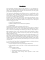
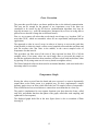
As it is shown in the figure below, for demonstration purposes we decided to limit our
project to a system that performs the following tasks:
•
measures temperature with a sensor connected to the FPGA board;
•
sends temperature values to the Palm via IR link, without storing them on the
board;
•
processes the data on Palm:
o performs error correction;
o plots graph with temperature variation over time;
o sends warning e-mail messages when temperature exceeds certain
threshold values;
3
o sends collected data from Palm to a server on the Internet via TCP/IP
connection. The server processes the data and plots a graph that is posted
on the web page.
Temperature
Sensor
INTERNET
PALM
FPGA board
Phone
Line
IR
IR Trans
IR Rec
Serial
Port
Modem
In order to complete our goal, we needed to complete the following tasks:
•
select a temperature sensor and connect it to the board;
•
add IR transmitter to the board;
•
design the controlling hardware implemented in the on-board FPGA;
•
program the Palm for:
o support for IR communication between the board and the Palm;
o support for the Internet connection from Palm through the modem;
•
develop a server application for receiving and plotting data;
•
design a web page to display the uploaded data.
4
Chapter 1. Description of the hardware used in the project
Temperature Sensor
We used TMP04FT9 temperature sensor made by Analog Devices. This sensor has a
wide temperature range (-40°C to +150°C) with the accuracy ±1.5°C (in -25°C to
+100°C range) [13]. The temperature detector has modulated serial digital output, with
the ratio of high and low period being directly proportional to the temperature of the
device. This significantly simplifies its interfacing to the microprocessorless FPGA
board, because it eliminates the need of ADC and calibration procedures (in comparison
with thermoresistor) and it doesn’t require implementing the two-way protocol in
hardware, which we would need to do if we used Dallas Semiconductors i-Button.
The output of the sensor is a square wave with the high and low periods T1 and T2 (see
the figure below):
The period T1 is approximately 5 - 15 ms, while T2 varies in 10 – 40 ms interval.
The temperature can be calculated using the following formulas:
400 × T 1
Temperature(C) = 235 −
T2
720 × T1
Temperature(F) = 455 −
T2
Since both periods are obtained consecutively and the formulas depend
on their ratio only, the temperature readings are independent of the drift
in either originating clock in TMP04 or the clock of the FPGA board that
is used for the period measurements. The sensor is laser-trimmed for
accuracy and linearity during manufacture and do not require any further
calibration.
The model TMP04FT9 we use uses TO-92 package, which we mounted
on the separate PCB and connected with the main board using 3-wire
cable (see figure on the right).
5
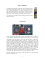
Infrared Transmitter
To send data to the Palm PDA via IrDA link, we used NTE3017 infrared
GaAs emitting diode (NTE Electronics, Inc.). Its emission wavelength is
950 nm, angle of half intensity is ±22 degrees and radiant power is 15
mW. The nominal continuous current of NTE3017 is 150 mA, while the
output current of FPGA I/O pin is only 25 mA [3]. That is why we had to
add a simple, one-stage amplifier (see schematics on the next page).
The infrared diode is mounted on the PCB connected to the FPGA board
(figure on the right).
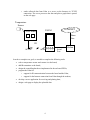
FPGA Board
For processing the signal from temperature sensor and sending the data to the Palm, we
used the University Program Design Laboratory Package made by Altera Corporation
(figure above). This board contains two FPGAs from MAX7000 and FLEX10K families,
several LED displays and switches, and the oscillator [1]. From the board we use only
MAX7000 family FPGA (EPM7128S) for processing the data, dual-digit 7-segment LED
display for controlling the changes in the temperature (it is displaying the hexadecimal
number, proportional to the low-period T2), and oscillator 25.175 MHz as the clock
source for the FPGA. We decided to use MAX7000 FPGA because it stores its
configuration in the internal EEPROM and does not require special programmer
hardware for external EEPROM or computer to download the configuration after powerup. The internal EEPROM of EPM7128S is programmed via FPGA JTAG pins,
connected to the printer port of the IBM PC, under MAX+PLUS II software control.
FPGA EPM7128S contain 128 macrocells, each of it consists of one flip-flop and five
product terms. The equivalent number of usable gates for this FPGA is 2500.
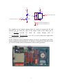
Schematic diagram for the interfacing of the temperature sensor and the infrared
transmitter is depicted below:
6
+5V
R2
+5V
27
R3
27
U1
TMP04
V+
D1
NTE3017
C1
0.047uF
C2
22uF
Connector P1 (FPGA pin 10)
GND
R1 1.2 k
Connector P1 (FPGA pin 11)
Dout
Q1
NTE2363
GND
+5V
GND
Connector MAX_EXPANSION pins 3, 5
Connector MAX_EXPANSION pins 4, 6
GND
The amplifier for the infrared emitting diode D1 consists of resistors R1, R2 and
transistor Q1. R1 limits the value of the output current of the FPGA pin to
Vcc − 0.7V
= 3.6mA and
R2 limits the current through LED to
R1
Vcc − Vled − 0.2V 5V − 1.7V − 0.2V
=
=
= 115mA . R3, C1 and C2 form power supply filter
27
R2
Ifpga _ out =
Iled
for the temperature sensor U1.
All the components except temperature detector U1 and C1 are mounted on the PCB,
which is mounted on the connectors P1, P3 and MAX_EXPANTION of the FPGA board
[1]. The FPGA board with our PCB attached is shown on the figure below.
7
FPGA Programming
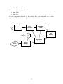
FPGA was programmed using MAX+PLUS II software with Verilog hardware
description language. The block diagram of the designed hardware is depicted on the
figure below.
Library 1
Clock
Generator
FPGA
IrDA Protocol
Generator
Infrared
Transmitter
Control
Unit
Temperature
Sensor
Time Intervals
Measurement
Unit
Display
Decoder
Library 2
2-digit
Display
Clock Generator, Temperature Sensor, Infrared Transmitter and 2-digit Display are
located on/connected to the FPGA board and are external as regards to the FPGA chip.
IrDA Protocol Generator has four inputs:
IrDA
gen
clk
byte_to_send [7:0]
led out
tclk
load
start
•
clk – clock frequency input;
•
byte_to_send – 8-bit data input;
•
load – when load=1, input data are copied to the internal register from which they
will be send using IrDA protocol later;
•
start – after setting this input to 1 the data from internal register are transmitted
via infrared LED using IrDA physical layer protocol;
•
led_out – output to which infrared LED should be connected;
•
tclk – output with IrDA_Speed_bod frequency.
8
This library module has two parameters:
•
IrDA_Speed_bod - IrDA transmitting rate, 9600 bod by default;
•
Clock_Freq_Hz – on-board clock frequency, 25175000 Hz by default.
Time
measur
clk
temp_inp
temp1[11:0]
temp2[11:0]
measure
Next library module, Time Intervals Measurement Unit (above figure), has following
ports:
•
clk – input clock frequency;
•
temp_inp – signal from the TMP04 temperature sensor;
•
measure – when “1”, updates internal registers temp1 and temp2 with the results
of high-period and low-period measurements;
•
temp1, temp2 – outputs of the internal 12-bit registers which hold the measured
value for high-period and low-period signal measurements.
Control Unit synchronizes the work of the previous two modules. The communication
protocol it implements (that works over IrDA Physical Layer Protocol) is described later
in this chapter.
Display Decoder converts the least significant byte of temp2 into hexadecimal
representation that is displayed on the on-board 2-digit display.
The total size of the source code is approximately 200 lines, below is some of the
statistics reported by the synthesis tool:
Total logic cells used:
123/128 ( 96%)
Total flipflops required:
89
Total product terms required:
398
IrDA Physical Layer Protocol
Our FPGA board with sensor sends measured values to the Palm via infrared link using
IrDA Physical Layer protocol as a physical layer protocol and communication protocol
described in the next section that uses IrDA Physical Layer Protocol as an underlying
protocol.
9
According to the IrDA Physical Layer specification [12] for the signaling rates up to
115.2 kb/s, the data are send as a stream of frames. Each frame consists of Start Bit, 8
Data Bits and a Stop Bit. No Parity Bit is used. All bits are encoded using RZI (Returnto-Zero-Inverted) modulation, that means that “0” is represented by a pulse with a
duration of 3/16 of a bit period, and “1” is represented by no pulse. Least significant bit is
transmitted first.
We use 9600 b/s transmission rate in our project.
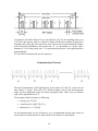
Communication Protocol
a
b
c
a
The board transmits the 12-bit high and low period values (T1 and T2) as the series of
three frames: a, b and c. The value of T1 does not change a lot over the all temperature
range, the most significant 4 bits are always staying the same. That is why we transmit
only 8 least significant bits of T1.
The meaning of the 8-bit frames is following:
•
first byte (a): T1[7:0]
•
second byte (b): {000, T2[11:7]}
•
third byte (c): {1, T2[6:0]}
For each measurement, two set of frames (a, b, c) are transmitted with the same values. In
one second five measurements are made and 10 sets of frames are transmitted.
10
Chapter 2. IR Communication using Palm
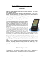
Introduction
Palm PDAs are the handhelds with the high success on the market today. They are easy
to use, small and affordable.
All Palm devices have a similar architecture, with small differences in term of size,
memory, and other characteristics. They include a LCD touchscreen with a resolution of
160x160, flash ROM, RAM (2/4/8 Mb), Motorola 68328 processor (and newer variants
of it), serial peripheral interface (up to 115200 bps), infrared communication support
(IrDA capability) and simple sound. The small screen size
poses some problems when designing programs for the Palm
(user interface).
The PDAs operate using PalmOS operating system, which is
based on a real-time multitasking kernel (Kadak). However,
only the operating system has access to it, user programs are
single-threaded, with only one program being executed at any
time. This also imposes some restrictions the programmer has
to deal with.
For our implementation we chose Palm IIIxe, one of the
entry-level version. This particular device has a monochrome
screen, 2Mb of flash ROM, 8Mb of RAM and a Motorola
16MHz MC68EZ328 processor. It runs on a pair of AAA
batteries. The low frequency of the processor means that we
should try to optimize our programs so that they do not overwhelm the processor. The
processor also does not have a floating-point unit (floating point operations are done in
software), so floating point computations should be avoided whenever possible.
The operating system running on Palm IIIxe is PalmOS 3.5. Since version 2.0, PalmOS
has brought new features to the Palm compatible devices, like infrared capability, serial
capability of up to 115200kbps, support for up to 16 gray levels on monochrome screens,
etc.)
PalmOS includes a standard TCP/IP stack implementation, which facilitates building
networking applications. Connection to external networks (like Internet) can be done
using serial modems (built-in support) or directly in case of wireless enabled devices
(Palm VII).
Palm IrDA Implementation
The standard IrDA stack comprises a number of protocol layers, of which some are
required and some are optional. The complete stack looks like in the figure below:
11
The SIR/FIR layer is purely hardware. The SIR (Serial IR) layer supports speeds up to
115k bps while the FIR (Fast IR) layer supports speeds up to 4M bps. IrLAP is the IR
Link Access Protocol that provides a data pipe between IrDA devices. IrLMP, the IR
Link Management Protocol, manages multiple sessions using the IrLAP. Tiny TP is a
lightweight transfer protocol on which some higher-level IrDA layers are built.
IrComm provides serial and parallel port emulation over an IR link. IrLAN provides an
access point to Local Area Network protocol adapters.
OBEX is an object exchange protocol that can be used (for instance) to transfer business
cards, calendar entries or other objects between devices.
The Palm OS implements all the required protocol layers (SIR, IrLAP, IrLMP, and Tiny
TP), as well as the OBEX layer. Palm III devices provide SIR (Serial IR) hardware
supporting the following speeds: 2400, 9600, 19200, 38400, 57600, and 115200 bps. The
stack is capable of connection-based or connectionless sessions.
From the IrDA layers Palm provides, we use only the lower level, SIR level. In PalmOS,
the SIR level of IrDA can be accessed through the New Serial Manager, which is capable
of managing multiple serial connections within a Palm device.
The main difference between the new serial manager and previous versions is that the
new serial manager supports multiple physical serial hardware devices and virtual serial
devices, the detailed operation of which is abstracted from the main serial management
code.
The new serial manager manages multiple serial devices with minimal duplication of
hardware drivers and data structures. In older Palm systems, the serial library managed
any and all connections to the serial hardware in the 68328 (Dragonball) processor, which
was the only serial device in the system. Newer systems contain additional serial devices,
such as an IR port.
The figure below shows the layering of communication software with the new serial
manager and hardware drivers:
12
The new serial manager maintains a database of installed hardware and currently open
connections. Applications, libraries, or other serial communication tasks open different
pieces of serial hardware by specifying a logical port number or a four-character code
identifying the exact piece of serial hardware that a task wishes to open a connection
with. The new serial manager then performs the proper actions on the hardware via small
hardware drivers that are opened dynamically when the port is needed.
Once a port is opened, the new serial manager allocates a structure for maintaining the
current information and settings of the particular port. The task or application that opens
the port is returned a port ID and must supply the port ID to refer to this port when other
new serial manager functions are called.
Upon closing the port, the new serial manager deallocates the open port structure and
unlocks the driver code resource to prevent memory fragmentation.
From hardware point of view, the UART unit in MC68EZ328 controls the infrared
LED/sensor. The UART unit also drives the 5-wire serial interface (used for hotsyncing
and for connecting to external devices – modems).
IR Receiver
Receiving the infrared stream of data is relatively simple with the help of New Serial
Manager, since it is very similar to standard serial communication. There are functions
provided for opening a serial connection, checking availability of bytes in the receive
buffer, waiting for a specified number of bytes to come, reading the buffer and closing
the connection.
13
In our case, the communication is unidirectional, the board does not have receive
capabilities. It continuously sends the data read from the sensor and formatted according
to our protocol.
From the previous sections, the protocol we choose for transmitting the temperature
values from the board to Palm consisted of a series of 3 bytes, which we refer to as a,b
and c in the next paragraphs.
Besides receiving the data from the infrared port and computing the temperature, the
receiver software on Palm should be able to also provide synchronization with the data
stream (a, b, c in the correct sequence), correct all the possible errors or signal if
something is wrong (e.g.: no data stream is present).
For synchronization, we observe that the three bytes received always have the following
properties:
•
a – no special property
•
b – starts with bit ‘0’
•
c – starts with bit ‘1’
Using these properties of a, b, c we can always decide if a sequence of 3 consecutive
bytes is in the correct sequence ([a, b, c]) or not ([b, c, a] or [c, a, b]). Moreover, we can
take measures to ensure correct synchronization at the beginning of next group of 3 bytes.
For that we might need to read additional one or two bytes from the stream.
If for any reasons, during any of the reads we specified above we get an error, the whole
process starts from beginning, after signaling the error.
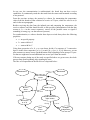
The flow of all operations in the IR receiver is depicted below:
Events
Initialization
Finalization
Test external
events
No events
Read 3 bytes
Receive
Error
Bit Error
Bit Error
Synchronization?
(Byte order)
Read bytes
(1 or 2)
Wrong
Sync.
Error
Correct
Compute
Temperature
14
Error Correction
The procedure specified above can detect problems due to the infrared communication.
This may not be enough for the purpose of our experiment: even if the bytes are
considered to be correct by the IR receiver synchronization algorithm, they may be
logically incorrect (e.g.: weak IR transmission, interpreted by receiver in wrong data or
packets lost or data out of range due to different factors).
First, we try to remove all values that are obviously out-of-range (e.g. less than -50°C or
more than 150°C, which are reasonable values for our experiments, and depend on the
application).
The approach we take in case of errors, in order to at least try to recover the good data
when possible is relatively simple: collect several sampled values and then sort them and
pick the median value (the value in the middle) as the correct sampled value of
temperature for that interval.
This procedure can filter most of the errors if they represent less than 50% of all the
sampled values. If too many values are out-of-range, then we just mark the sample as
invalid (the application that uses these numbers will have to deal with invalid data, either
by ignoring it or by using some sort of recovery based on neighbor values).
The filtered sampled values are then stored in an internal database, each associated with a
timestamp when it was taken.
Temperature Graph
Having the values received form the board and error corrected, we want to dynamically
output them on the Palm screen in a graphical way. We have implemented a simple
dynamic graph viewer on Palm, which shows the last 130 sampled values of temperature.
Due to Palm limited screen resolution we cannot show more than that in a clear way.
The graph is implemented in two separate functions (one that draws the frame, called
only once, and another that does the update of the graph, called after each sampling, and
optimized for fast response).
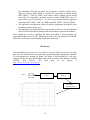
The displayed graph looks like in the next figure (there is also a screenshot of Palm
showing it)
15
Temperature
Temp Max
Temp Min
0
Past time
Temp Max and Temp Min are thresholds used by the temperature monitoring application
to trigger some actions when they are crossed (see next chapter).
Temperature Monitoring
In addition to displaying the history of values on the screen, our application also collects
all data in an internal database stored on Palm. Periodically, the content of the database is
uploaded to an Internet server using the network capabilities of Palm (see next chapter).
Due to a lack of available resources on Palm (there is only one UART unit), collection of
temperature values needs to be interrupted during network transmissions and resumed
afterwards.
Integration
We grouped the functions handling specific actions into libraries:
IR Sampling library - functions dealing with the infrared communication/data sampling.
They provide:
•
Initialize IR communication
•
Get sample data
•
Sort data
•
Compute median value
•
Verify data validity
16
•
Close IR communication
Functions for drawing the graph:
•
Draw frame
•
Draw data
All the components described in this chapter have been integrated into a demo
application. The structure of the application is presented below:
Error
Correction
IR Receiver
Temperature
Graph
IR
User
Interface
Database
Application
Manager
Internet
Network
Manager
17
Chapter 3. Networking
Introduction
The Palm SDK contains a net library that provides network services, like TCP/IP, to
applications. With this library, an application on the Palm device can connect to any other
machine on a network using standard TCP/IP protocols. The API for this library is a
socket interface, modeled very closely on the Berkeley Sockets API.
The similarity between the Berkeley Sockets API and the net library is so close that the
Berkeley Sockets source code can be compiled for the Palm OS with minor-and
sometimes no-changes. As a result, porting networking code to the Palm OS is very
simple. The code can also be ported to any portable Unix-like platforms, like Agenda
VR3.
The code was developed on a Unix platform and then just compiled for Palm OS. Much
more sophisticated debugging tools are available in the Unix/Linux world than for Palm
OS.
Constraints
Currently, TCP/IP communication standard is available only via a serial or modem
connection. As mentioned in the previous chapter, IR communication is available only
via the serial port. This means that:
•
There cannot be IR communication and TCP/IP connection at the same time.
Therefore, the TCP/IPC connection starts only when there is data to transmit, or
when the user initiates a transfer. It terminates immediately after the data was
transferred.
•
After the TCP/IP connection is initiated, if any kinds of errors are encountered,
our application has to assure that it terminates the TCP/IP connection, in order to
unlock the resources, i.e. serial port.
The Client
Our Palm application executes a temperature-monitoring loop. While in this loop, the
serial port is used for IR communication with the board. There are 3 situations in which
the application can terminate IR communication and start a TCP/IP connection.
•
If the temperature is below or above certain thresholds (current_temp <
MIN_TEMP or MAX_TEMP < current_temp), the application sends a warning email message. After that, it waits until the temperature reaches values between the
18
two thresholds. However, in reality the temperature oscillates around values.
When for instance MIN_TEMP is reached, the temperature oscillates around
MIN_TEMP +/- DELTA_TEMP. This would result in sending e-mails all the
time while the temperature gradually increases around TEMP_MIN value. To
prevent that, we use a hysteresis, i.e. we do not send e-mails until the temperature
is between MIN_TEMP + DELTA_TEMP and MAX_TEMP – DELTA_TEMP.
•
The application can upload the collected values of temperature periodically, after
an interval specified by the user.
•
The application can upload the data at user request. In this case, it will send all the
values collected from the beginning of the interval that are stored in the database.
After sending the e-mail or uploading the data (successfully or unsuccessfully), the
application terminates the TCP/IP connection in order to free the serial port for IR link.
After that, it will resume monitoring the temperature in the loop.
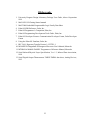
The Server
The functionality of the server is very simple. It receives all the data sent by the client
into a text file. Based on this file it generates a graph showing the temperature variation.
We used gnuplot for drawing the graph. The image is later included in a web page,
updated with the last upload time stamp, and can be accessed on the Internet, with any
available
Web
browser.
The
Web
page
of
the
project
is
http://www.ics.uci.edu/~isse/proj213/.
D atabase
C lient
(Palm )
N etw ork
M anager
Server
receives data
generates graph
19
We developed a simple communication protocol used between the client on Palm and the
server for uploading data. The server runs on a Unix host. It uses port number 7002,
which should be available. If it is not, the port number can be easily changed.
The figure on the previous page shows the data flow from Palm client to the server, and a
sample graph as it appears on the web page.
Functions
We developed a collection of generic functions for basic TCP/IP communications.
static int make_connection(char *service, int type, char
*netaddress)
/* This is a generic function to make a connection to a given server/port.
service is the port name/number,
type is either SOCK_STREAM or SOCK_DGRAM, and
netaddress is the host name to connect to.
The function returns the socket, ready for action.*/
static int atoport(char *service, char *proto)
/* Take a service name, and a service type, and return a port number. The number
returned is byte ordered for the network. */
static struct in_addr *atoaddr(char *address)
/* Converts ascii text to in_addr struct. NULL is returned if the address can not be
found. */
static int sock_gets(int sockfd, char *str, size_t count)
/* This function reads from a socket, until it receives a linefeed character. It fills the
buffer "str" up to the maximum size "count". This function will return -1 if the socket
is closed during the read operation.If a single line exceeds the length of count, the
extra data will be read and discarded */
static int sock_puts(int fd, char *body)
/* This function writes to a socket all the newline-terminated lines contained in body.
This function will return -1 if the socket is closed during the write operation.*/
Using the above functions, we developed two more complex functions, which are also
very general: sendmail() and senddata(). In order to maintain the generality of these
20
functions, two of the parameters are pointers to functions for printing the status and error
message. These functions are platform dependent.
typedef void
typedef void
*extraInfo);
(*StatusCallbackFunc)(char *status);
(*ErrorCallbackFunc)(char *problem, char
int sendmail(char *smtpHost, char *from, char *to, char
*subject, char *data, StatusCallbackFunc statusFunc,
ErrorCallbackFunc errorFunc)
/* Sends e-mail to a user by connecting to the STMP server smtpHost. From, to and
subject are self-explanatory. data is the body of the message. statusFunc and
errorFunc are explained above. */
int senddata(char *Host, char *port, struct pair data[], int
N, StatusCallbackFunc statusFunc, ErrorCallbackFunc
errorFunc);
/* Sends N elements of data to a server at Host and port. */
21
Conclusions
We provided the infrastructure for monitoring, processing and publishing sensor data.
We connected the temperature sensor and IR transmitter to FPGA board. The temperature
data acquisition is displayed on the board, as well as transmitted to the Palm via IR link.
For programming the board we developed an IrDA_generator library and a
Temperature_Measurement library.
Programming the Palm provide:
•
IR communication with the board
•
Error correction
•
IR communication library
•
Graph display – generic functions for drawing
•
Internet communication using Palm and modem
•
Generic communication functions
•
Send mail and Send data
We integrated all the components and developed a demo application that shows all the
capabilities described above.
22
Bibliography
1. University Program Design Laboratory Package User Guide, Altera Corporation
1999
2. MAX+PLUS II Getting Started manual
3. MAX7000 Embedded Programmable Logic Family Data Sheet
4. Palm OS SDK Reference, Palm, Inc.
5. Palm OS Programmer’s Companion, Palm, Inc.
6. Palm OS Programming Development Tools Guide, Palm, Inc.
7. Palm OS Developer Forums: Communication Developer Forum, Palm Developer
Forum
8. Using the Palm OS Emulator, Palm, Inc.
9. RFC 2616: Hypertext Transfer Protocol -- HTTP/1.1
10. MC68EZ328 Dragonball-EZ Integrated Processor User's Manual, Motorola.
11. MTOROLA M68000 FAMILY Programmer s Reference Manual, Motorola.
12. Serial Infrared Physical Layer Specification, Ver. 1.3, Infrared Data Association,
1998
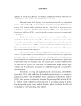
13. Serial Digital Output Thermometers TMP03/TMP04 data sheet, Analog Devices,
1995
23