1
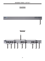
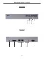
SENDER PANEL DESCRIPTIONS
1
Power LED Indicator
This LED will become active once the included 5V DC power supply is properly
connected between the unit and an open wall power socket.
2
RS-232 Serial Communication Input 1-4
These inputs will support RS-232 serial communications devices. Only pins
2 (RX), 3 (TX), and ground (5) are supported. Four inputs are provided. The
CAT5•4000 receiver units must be configured for RS-232 operation for either
channel 1 (both outputs) or for channels 2 and 3. Please see page 14.
3
Channel 1 VGA and Audio RJ-45 Port 1-2
When the input video source is analog, these RJ-45 ports connect the
CAT5•4000 sender to a CAT5•4000 receiver unit using CAT-5, CAT-5e or CAT-6
cabling. Analog video and audio are transmitted through this connector. Two
ports are provided for mirrored video output of the channel 1 source to two
separate locations. If RS-232 extension is required, a second CAT-5 cable must
be connected using the channel 1 DVI/RS-232 RJ-45 port. Once a link between
the sender and receiver unit has been established, the green LED indicator
located on these ports will become active.
4
Channel 1 DVI and RS-232 RJ-45 Port 1-2
When the input video source is digital, these RJ-45 ports connect the
CAT5•4000 sender to a CAT5•4000 receiver unit using CAT-5, CAT-5e or CAT-6
cabling. Digital video and RS-232 are transmitted through this connector. Two
ports are provided for mirrored video output of the channel 1 source to two
separate locations. If audio extension is required, a second CAT-5 cable must be
connected using the channel 1 VGA/RS-232 RJ-45 port. Once a link between
the sender and receiver unit has been established, the green LED indicator
located on these ports will become active.
5
Channel 1 DVI Input
Connect an analog or digital source to this DVI-I input port. Depending on the
input video signal type, analog or digital, a mirrored signal will be output to either
the dual VGA or DVI RJ-45 ports.
6
3.5mm Analog Stereo Audio Mini-Jack Input
Connect an analog stereo audio source to this input port. The audio source
connected to this input will be mirrored and output through both of the VGA/
Audio RJ-45 ports. This audio source will not be output through any of the
channel 2 and 3 RJ-45 output ports.
7
Channel 2 VGA/RS-232 and DVI/DDC RJ-45 Ports
These RJ-45 ports connect the CAT5•4000 sender to a CAT5•4000 receiver unit
using CAT-5, CAT-5e or CAT-6 cabling. When the input source is analog, the
VGA/RS-232 port is used. When the input source is digital, the DVI/DDC port
is used. If RS-232 is required when using a digital input source, use both RJ-45
ports.
8
Channel 2 DVI Input
Connect an analog or digital source to this DVI-I input port.
5