1
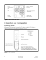
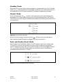
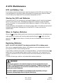
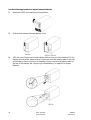
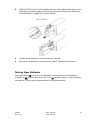
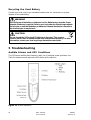
UPS 1000 - 2200 VA
User’s Manual
Powerware 5125 User’s Manual 1000–2200 VA
1019297
Revision A
Table of contents
1. Introduction ............................................................................................................. 7
2. Installation ............................................................................................................... 8
Inspecting the Equipment ............................................................................................ 8
Installing the UPS ......................................................................................................... 8
UPS Rear Panels ........................................................................................................... 9
3. Operation and Configuration .................................................................................. 10
Operating Models ....................................................................................................... 10
Stanby mode ................................................................................................................ 11
Normal Mode .............................................................................................................. 11
Buck and Double Boost Mode .................................................................................... 11
Battery Mode ............................................................................................................... 12
Sleep Mode .................................................................................................................. 12
UPS Configuration ...................................................................................................... 12
Turning the UPS On .................................................................................................... 12
Starting the UPS on Battery ........................................................................................ 12
Turning the UPS Off .................................................................................................... 13
Initiating the Self-Test ................................................................................................. 13
Communication Port .................................................................................................. 13
Network Transient Protector ..................................................................................... 14
Load Segments ............................................................................................................ 15
4. UPS Maintenance .................................................................................................... 16
UPS and Battery Care ................................................................................................. 16
Storing the UPS and Batteries .................................................................................... 16
When to Replace Batteries ......................................................................................... 16
Replacing Batteries ...................................................................................................... 16
Testing New Batteries ................................................................................................. 19
Recycling the Used Battery ......................................................................................... 20
5. Troubleshooting ...................................................................................................... 20
Audible Alarms and UPS Conditions ......................................................................... 20
Silencing an Audible Alarm ........................................................................................ 21
6. Specifications .......................................................................................................... 23
Copyright 2002
The contents of this manual are the copyright of the publisher
and may not be reproduced (even extracts)
unless permission granted.
Every care has been taken to ensure the accuracy of
the information contained in this manual, but no liability
can be accepted for any errors or omission. The right
to make design modifications is reserved.
Requesting a Declaration of Conformity
Units that are labeled with a CE mark comply with the following harmonized standards
and EU directives:
• Harmonized Standards: EN 50091-1-1 and EN 50091-2; IEC 950 Second Edition,
Amendments A1, A2, A3, and A4
• EU Directives:
73/23/EEC, Council Directive on equipment designed for use
within certain voltage limits
93/68/EEC, Amending Directive 73/23/EEC
89/336/EEC, Council Directive relating to electromagnetic
compatibility
92/31/EEC, Amending Directive 89/336/EEC relating to EMC
The EC Declaration of Conformity is available upon request for products with a CE
mark. For copies of the EC Declaration of Conformity, contact:
Powerware Oy
Koskelontie 13
FIN-02920 Espoo, Finland
Phone: +358-9-452 661
Fax: +358-9-452 66 396
Class A EMC Statements
(1000–1500 VA Models)
FCC Part 15
NOTE This equipment has been tested and found to comply with the limits for a Class
A digital device, pursuant to part 15 of the FCC Rules. These limits are designed to
provide reasonable protection against harmful interference when the equipment is
operated in a commercial environment. This equipment generates, uses, and can radiate
radio frequency energy and, if not installed and used in accordance with the instruction
manual, may cause harmful interference to radio communications. Operation of this
equipment in a residential area is likely to cause harmful interference in which case the
user will be required to correct the interference at his own expense.
ICES-003
This Class A Interference Causing Equipment meets all requirements of the Canadian
Interference Causing Equipment Regulations ICES–003.
Cet appareil numérique de la classe A respecte toutes les exigences du Reglement sur le
matériel brouilleur du Canada.
Special Symbols
The following are examples of symbols used on the UPS to alert you to important
information:
RISK OF ELECTRIC SHOCK - Indicates that a risk of electric shock is
present and the associated warning should be observed.
CAUTION: REFER TO OPERATOR’S MANUAL - Refer to your operator’s
manual for additional information, such as important operating and
maintenance instructions.
RJ-45 RECEPTACLE - For 230V units only: this receptacle provides network
interface connections. Do not plug telephone or telecommunications
equipment into this receptacle.
This symbol indicates that you should not discard the UPS or the UPS
batteries in the trash. The UPS may contain sealed, lead–acid batteries.
Batteries must be recycled.
1 Powerware 5125 – Introduction
The Powerware® 5125 uninterruptible power system (UPS) protects your sensitive
electronic equipment from basic power problems such as power failures, power sags,
power surges, undervoltage and overvoltage.
Power outages can occur when you least expect it and power quality can be erratic. These
power problems have the potential to corrupt critical data, destroy unsaved work sessions,
and damage hardware — causing hours of lost productivity and expensive repairs.
With the Powerware 5125, you can safely eliminate the effects of power disturbances and
guard the integrity of your equipment. The Powerware 5125 was designed for critical
applications such as PCs, severs, workstations, and telecommunications equipment. Figure
1 shows the Powerware 5125 UPS with an optional Extended Battery Module (EBM).
Figure 1. The Powerware 5125
Providing outstanding performance and reliability, the Powerware 5125’s unique benefits
include the following:
• Advanced Battery Management Plus (ABM Plus™) doubles battery service life,
optimizes recharge time, and provides a warning before the end of useful battery life.
• Buck and Double Boost regulation ensures consistent voltage to your load by
correcting voltage fluctuations without using battery power.
• Hours of extended run time with up to four EBMs.
• Hot–swappable batteries simplify maintenance by allowing you to replace batteries
safely without powering down the critical load.
• Start–on–battery capability allows you to power up the UPS even if utility power is
not available.
• Advanced power management with the Software Suite CD for graceful shutdowns
and power monitoring.
• Sequential shutdown and load management through separate receptacle groups,
called load segments.
• Network Transient Protector guards your network communications equipment from
surges.
• Optional X-Slot™ modules provide enhanced communication capabilities for
increased power protection and control.
• The Powerware 5125 is backed by worldwide agency approvals.
1019297
Revision A
1000 - 2200 VA
User’s Manual
7
2 Installation
Inspecting the Equipment
If any equipment has been damaged during shipment, keep the shipping cartons and
packing materials for the carrier or place of purchase and file a claim for shipping
damage. If you discover damage after acceptance, file a claim for concealed damage.
To file a claim for shipping damage or concealed damage: 1) File with the carrier within
15 days of receipt of the equipment; 2) Send a copy of the damage claim within 15 days
to your service representative.
Installing the UPS
The following steps explain how to install the UPS. See “UPS Rear Panels” on page 9 for
the rear panel of each model.
NOTE Do not make unauthorized changes to the UPS; otherwise, damage may occur
to your equipment and void your warranty.
1.
If installing an optional EBM, continue to Step 2; otherwise, skip to Step 4.
2.
Plug the EBM cable into the battery connector on the UPS rear panel.
3.
If a second EBM is to be installed, plug the EBM cable of the second cabinet into
the battery connector on the first EBM. Up to four EBMs may be connected to the
UPS.
4.
If you are installing power management software, connect your computer to the
UPS communication port using the supplied communication cable.
5.
Plug the detachable UPS power cord, into the input connector on the UPS rear
panel.
6.
Plug the UPS power cord into a power outlet. The front panel indicators cycle
through a startup sequence while the UPS conducts a self–test.
indicator flashes, indicating the UPS is in
When the self-test is complete, the
Standby mode with the equipment offline. If the alarm beeps or a UPS alarm
indicator stays on, see Table 2 on page 22.
7.
Plug the equipment to be protected into the appropriate UPS output receptacles
(see page 15 for more information on load segments).
DO NOT protect laser printers with the UPS because of the exceptionally high
power requirements of the heating elements.
8.
Press and hold the On button until you hear the UPS beep (approximately one
second). The indicator stops flashing and the bar graph indicators display the
percentage of load being applied to the UPS.
The UPS is now in Normal mode and supplying power to your equipment.
8
1000 - 2000 VA
User’s Manual
1019297
Revision A
NOTE. The batteries charge to 90% capacity in approximately 3 hours. However, it is
recommended that the batteries charge for 24 hours after installation or long-term
storage.
NOTE. If more than two EBMs are installed, an external battery charger is
recommended for faster recharge times.
Figure 2. Installation
UPS Rear Panels
This section shows the rear panels of the Powerware 5125 models.
Figure 3. PW5125 1000i and PW5125 1500i Rear Panel
1019297
Revision A
1000 - 2200 VA
User’s Manual
9
Figure 4. PW5125 2200i Rear Panel
3 Operation and Configuration
Operating Modes
Powerware 5125’s front panel indicates the UPS status through the UPS indicators.
Figure 5 shows the UPS front panel indicators and controls.
Figure 5. UPS Front Panel
10
1000 - 2000 VA
User’s Manual
1019297
Revision A
Standby Mode
When the UPS is turned off and remains plugged into a power outlet, the UPS is in Standby
mode. The
indicator flashes and the bar graph indicators are off, indicating that power is
not available from the UPS output receptacles. The battery recharges when necessary.
Normal Mode
During Normal mode, the
indicator illuminates and the front panel displays the
percentage of UPS load capacity being used by the protected equipment (see Figure 6).
The UPS monitors and charges the batteries as needed and provides power protection to
your equipment.
Figure 6. Load Level Indicators
When all of the bar graph indicators and the
indicator are illuminated, power
requirements exceed UPS capacity; see page 22 for more information.
Buck and Double Boost Mode
With the Buck and Double Boost feature, the UPS accepts a wide input voltage range
(-30%/+20% of nominal) and provides consistent, clean voltage to your equipment.
The UPS operates normally from utility power and alerts you of the voltage fluctuations.
indicator alternates between green and red while in Buck, Single Boost, or
The
Double Boost mode as shown in Figure 7.
Figure 7. Buck and Double Boost Indicators
1019297
Revision A
1000 - 2200 VA
User’s Manual
11
Battery Mode
When the UPS is operating during a power outage, the alarm beeps once every four
seconds and the
indicator illuminates. When the utility power returns, the UPS
switches to Normal mode operation while the battery recharges.
indicator flashes and the
If battery capacity becomes low while in Battery mode, the
alarm beeps twice every two seconds. Immediately complete and save your work to
prevent data loss and similar difficulties. When utility power is restored after the UPS
shuts down, the UPS automatically restarts.
Sleep Mode
If the UPS is on battery for approximately five minutes and supporting a small electrical
load (≤10%), the UPS shuts down the load. After three minutes in Sleep mode, the UPS
initiates a shutdown warning (two beeps every two seconds). This feature conserves
battery power. To enable this feature, contact your service representative.
UPS Configuration
Your PW5125 UPS can be configured by using a configuration software that can be find
on web (www.emea.powerware.com/product/PW5125.htm). This software is a DOS
based program that can be executed from either a DOS box, from a Windows shortcut,
or from the Windows Start, Run dialog box.
UPS setting that can be changed are as follow:
1.
Voltage setting 220/230/240 V (230 V is factory default)
2.
Enable/disable sleep mode (disable as factory default)
3.
Enable/disable audible alarm, so that when disable no audible alarms will be given
(Enable as factory default)
4.
Enable/disable site wiring detection (not supported on European model)
Turning the UPS On
After the UPS is connected to a power outlet, it conducts a self–test and enters Standby
mode. To turn on the UPS, press and hold the On button until you hear the UPS beep
(approximately one second). The
indicator stops flashing and the bar graph
indicators display the percentage of load being applied to the UPS.
Starting the UPS on Battery
NOTE Before using this feature, the UPS must have been powered by utility power at
least once.
To turn on the UPS without using utility power, press and hold the On button for at least
four seconds. The UPS supplies power to your equipment and goes into Battery mode.
12
1000 - 2000 VA
User’s Manual
1019297
Revision A
Turning the UPS Off
To turn off the UPS, press and hold the Off button until the long beep ceases
(approximately five seconds). The
indicator begins to flash and the UPS remains in
Standby mode until you unplug the UPS from the power outlet.
Initiating the Self–Test
NOTE. The batteries must be fully charged to perform the self–test.
Press and hold the On button for three seconds to initiate the self–test. During the test,
individual indicators illuminate as various parts of the UPS are checked. If the alarm
beeps or a UPS alarm indicator stays on, see Table 2 on page 22.
Communication Port
The Powerware 5125 is factory-installed with a Single-Port Module.
To establish communication between the UPS and a computer, connect your computer
to the UPS communication port using the supplied communication cable.
When the communication cable is installed, power management software can exchange
data with the UPS. The software polls the UPS for detailed information on the status of
the power environment. If a power emergency occurs, the software initiates the saving
of all data and an orderly shutdown of the equipment.
The cable pins are identified in Figure 8 and the pin functions are described in Table 1.
Figure 8. Communication Port
Pin
Number
Signal Name
Function
Direction from
the UPS
1
Low Batt
Low Battery relay contact
Out
2
RxD
Transmit to external device
Out
3
TxD
Receive from external device
In
4
DTR
PnP (Plug and Play) from external device
(tied to Pin 6)
In
5
GND
Signal common (tied to chassis)
—
6
DSR
To external device (tied to Pin 4)
Out
7
RTS
PnP from external device
In / Out
8
AC Fail
AC Fail relay contact
Out
9
Power Source
+V (8 to 24 volts DC power)
Out
Table 1. Communication Port Pin Assignment
1019297
Revision A
1000 - 2200 VA
User’s Manual
13
Network Transient Protector
The Network Transient Protector, shown in Figure 9, is located on the rear panel and
has jacks labeled IN and OUT. This feature accommodates a single RJ–45 (10BaseT)
network connector.
Connect the input connector of the equipment you are protecting to the jack labeled IN.
Connect the output connector to the jack labeled OUT.
Figure 9. Network Transient Protector
14
1000 - 2000 VA
User’s Manual
1019297
Revision A
Load Segments
Load segments are sets of receptacles that can be controlled by power management
software, providing an orderly shutdown and startup of your equipment. For example,
during a power outage, you can keep key pieces of equipment running while you turn
off other equipment. This feature allows you to save battery power. See your power
management software manual for details.
NOTE. If the power management software is not used, the individual load segments
cannot be controlled.
The following figures show the load segments for each UPS.
Figure 10. 1000 VA and 1500 VA Load Segments
Figure 11. 2200 VA Load Segments
1019297
Revision A
1000 - 2200 VA
User’s Manual
15
4 UPS Maintenance
UPS and Battery Care
For the best preventive maintenance, keep the area around the UPS clean and dust–free.
If the atmosphere is very dusty, clean the outside of the system with a vacuum cleaner.
For full battery life, keep the UPS at an ambient temperature of 25°C .
Storing the UPS and Batteries
If you store the UPS for a long period, recharge the battery every 6 months by plugging
the UPS into a power outlet. The batteries charge to 90% capacity in approximately
3 hours. However, it is recommended that the batteries charge for 24 hours after longterm storage.
Check the battery recharge date on the shipping carton label. If the date has expired and
the batteries were never recharged, do not use the UPS. Contact your service
representative.
When to Replace Batteries
When the
indicator flashes and there is a continuous audible alarm, the batteries may
need replacing. Conduct a self–test by pressing and holding the
seconds. If the
batteries.
button for three
indicator stays on, contact your service representative to order new
Replacing Batteries
NOTE DO NOT DISCONNECT the batteries while the UPS is in Battery mode.
With the hot–swappable battery feature, UPS batteries can be replaced easily without
turning the UPS off or disconnecting the load.
If you prefer to remove input power to change the battery: 1) Press and hold the Off
button until the long beep ceases (approximately five seconds), then unplug the UPS;
2) Wait 60 seconds while the internal processor shuts down before you disconnect the
battery.
Consider all warnings, cautions, and notes before replacing batteries.
WARNING
Batteries can present a risk of electrical shock or burn from high short-circuit
current. The following precautions should be observed: 1) Remove watches, rings,
or other metal objects; 2) Use tools with insulated handles; 3) Do not lay tools or
metal parts on top of batteries.
ELECTRIC ENERGY HAZARD. Do not attempt to alter any battery wiring or
connectors. Attempting to alter wiring can cause injury.
16
1000 - 2000 VA
User’s Manual
1019297
Revision A
How to Replace Extended Battery Modules
Use the following procedure to replace EBMs:
1.
Unplug the EBM cable from the UPS.
2.
Replace the EBM. See “Recycling the Used Battery” on page 20 for proper disposal.
3.
Plug the new EBM into the UPS as shown in Figure 12.
4.
For additional EBMs, plug the EBM cable of the second cabinet into the battery
connector on the first EBM.
Figure 12. EBM Connections
How to Replace Internal Batteries
CAUTION
Pull the battery out onto a flat, stable surface. The battery is unsupported when you
pull it out of the UPS.
1019297
Revision A
1000 - 2200 VA
User’s Manual
17
Use the following procedure to replace internal batteries:
1.
Remove the UPS front panel by pulling the top.
2.
Slide up and remove the metal battery cover.
3.
1000 VA units. Disconnect the red battery cable on the front of the battery. Pull the
battery out onto a flat, stable surface. Disconnect the black battery cable on the rear
of the battery, then on the front of the battery. Disconnect the red battery cable on
the rear of the battery. See “Recycling the Used Battery” on page 20 for proper
disposal.
18
1000 - 2000 VA
User’s Manual
1019297
Revision A
4.
1500 and 2200 VA units. Pull the battery out onto a flat, stable surface. Press on the
black tab on the battery cable connector to disconnect the battery. See “Recycling
the Used Battery” on page 20 for proper disposal.
5.
Install the new batteries in the reverse order of removal.
6.
Reinstall the metal battery cover removed in Step 2. Replace the front panel.
Testing New Batteries
Press and hold the
button for three seconds to initiate a self–test. After the test is
finished, the
indicator should turn off. If the
indicator stays on, check the battery
connections. Call your service representative if the problem persists.
1019297
Revision A
1000 - 2200 VA
User’s Manual
19
Recycling the Used Battery
Contact your local recycling or hazardous waste center for information on proper
disposal of the used battery.
WARNING
Do not dispose of the battery or batteries in a fire. Batteries may explode. Proper
disposal of batteries is required. Refer to your local codes for disposal requirements.
Do not open or mutilate the battery or batteries. Released electrolyte is harmful to
the skin and eyes. It may be toxic.
CAUTION
Do not discard the UPS or the UPS batteries in the trash. This product
contains sealed, lead–acid batteries and must be disposed of properly. For more
information, contact your local recycling or hazardous waste center.
5 Troubleshooting
Audible Alarms and UPS Conditions
The UPS has an audible alarm feature to alert you of potential power problems. Use
Table 2 to determine and resolve the UPS alarms and conditions.
Figure 13. Alarm Indicators
20
1000 - 2000 VA
User’s Manual
1019297
Revision A
Silencing an Audible Alarm
To silence the alarm for an existing fault, press the
button. If UPS status changes, the
alarm beeps, overriding the previous alarm silencing. The alarm does not silence if there
is a low battery condition.
Alarm or Condition
Possible Cause
Action
The
indicator is
not on; the UPS does
not start.
The power cord is not
connected correctly.
Check the power cord connections.
The wall outlet is faulty.
Have a qualified electrician test and repair
the outlet.
The
indicator is
flashing; power is not
available at the UPS
output receptacles.
The UPS is in Standby
mode.
Press the On button to supply power to
the connected equipment.|
The UPS does not
provide the expected
backup time.
The batteries need charging
or service.
Plug the UPS into a power outlet for 24
hours to charge the battery. After charging
the battery, press and hold the
button
for 3 seconds; then check the
indicator.
If the
indicator is still on, see "UPS
Maintenence" to replace the battery.
The self-test failed
Plug the UPS into a power outlet for at least
3 hours to charge the battery. After charging
the battery, press and hold the
button for
3 seconds; then check the
indicator.
If the
indicator is still on, shut down
the UPS and contact your service
representative.
UPS internal temperature is
too high.
The UPS shuts down automatically in
10 seconds. Turn off and unplug the UPS.
Clear vents and remove any heat sources.
Ensure the airflow around the UPS is not
restricted. Wait at least 5 minutes and restart
the UPS. If the condition persists, contact
your service representative.
UPS on battery.
The UPS is powering the equipment with
battery power. Prepare your equipment for
shutdown.
The battery is running low.
3 minutes or less of battery power remains
(depending on load configuration and
battery charge). Save your work and turn off
your equipment. The alarm cannot be
silenced.
1 beep every 4
seconds
2 beeps every 2
seconds
Table 2. Troubleshooting Guide
1019297
Revision A
1000 - 2200 VA
User’s Manual
21
Alarm or Condition
1 beep every 5
seconds.
100%
25%
22
Possible Cause
Action
The UPS is running on
battery power because the
input voltage is too high or
too low.
Correct the input voltage, if possible. The
UPS continues to operate on battery until
the conditions is corrected or the battery is
completely discharged.
If the condition persists, the input voltage in
your area may differ from the UPS nominal.
The utility line voltage and
frequency are out of
specification.
Have a qualified electrician check the
wiring.
The battery may be fully
discharged.
Plug the UPS into a power outlet for 24
hours to charge the battery. After charging
the battery, press and hold the
button
for 3 seconds; then check the
indicator.
If the
indicator is still on, see "UPS
Maintenance" to replace the battery.
The battery is not
connected correctly.
Check the battery connections. Call your
service representative if the problem
persists.
Ground wire connection
does not exist or the line
and neutral wires are
reversed in the wall outlet.
Have a qualified electrician correct the
wiring.
Power requirements exceed
UPS capacity (101–110% for
3 minutes or 111–150% for
10 cycles) or the load is
defective.
Turn off and unplug the UPS. Remove some
of the equipment from the UPS. Wait at
least 5 seconds until all LEDs are off and
restart the UPS. You may need to obtain a
larger capacity UPS.
UPS fault condition.
Save your work and turn off your
equipment. Turn off and unplug the UPS.
Contact your service representative. The
alarm cannot be silenced.
1000 - 2000 VA
User’s Manual
1019297
Revision A
6 Specifications
Model Number
Power Levels
(rated at nominal inputs)
Nominal Voltage
PW5125 1000i
1000 VA, 700 W
230 V
PW5125 1500i
1500 VA, 1050 W
230 V
PW5125 2200i
2200 VA, 1600 W
230 V
Input Voltage Range
154-288 V
(-30%/+20%)
Table 3. Model Specifications
Dimensions (W x D x H)
Weight
1000 VA Models
162 x 401 x 250 mm
15 kg
1500 VA Models
162 x 467 x 250 mm
23 kg
PW5125 2200i
205 x 493 x 250 mm
31 kg
Extended Battery Module
162 x 474 x 250 mm
27 kg
Table 4. Weights and Dimensions
Input Connection
Output Receptacles
PW5125 1000i
10 A, IEC-320 input connector
(6) 10 A, IEC 320-C13
PW5125 1500i
10 A, IEC-320 input connector
(6) 10 A, IEC 320-C13
PW5125 2200i
10 A, IEC-320 input connector
(9) 10 A, IEC 320-C13
Table 5. Power Connections
Operating Frequency
50/60 Hz, auto-sensing
Frequency Range
46–65 Hz
Noise Filtering
MOVs and line filter for normal and common mode noise
Regulation
(Normal mode)
-10% to +6% of nominal voltage
Regulation
(Battery mode)
Nominal output voltage ±5%
Voltage Waveform
Sine wave
Table 6. Technical Specifications
1019297
Revision A
1000 - 2200 VA
User’s Manual
23
Operating Temperature
10°C to 40°C
Optimal battery performance: 25°C
Storage Temperature
0°C to 25°C
Transit Temperature
-25°C to 55°C
Relative Humidity
5–95% noncondensing
Operating Altitude
Up to 3,000 meters above sea level
Transit Altitude
Up to 15,000 meters above sea level
Audible Noise
Less than 40 dBA Normal mode, typical load
Less than 55 dBA Battery mode
Surge Suppression
ANSI C62.41 Category B (formerly IEEE 587), IEC 61000-4-5
UL 1778, UL 497A (data line only);
CAN/CSA C22.2, No. 107.1;
EN 50091-1-1 and IEC 60950
Safety Conformance
Agency Markings
UL and cUL; CE, C-Tick, LGA/GS, DEMKO
EMC
EN 50091-2, FCC Part 15, ICES-003
Table 7. Environmental and Safety
1000 VA: (2) 24V, 9 Ah internal batteries
1500 VA: (4) 48V, 7 Ah internal batteries
2200 VA: (4) 48V, 12 Ah internal batteries
Configuration
EBM Configuration
PW5125 EBM-24: (8) 24V, 9 Ah batteries
PW5125 EBM-48: (8) 48V, 9 Ah batteries
Type
Sealed, maintenance–free, valve–regulated, lead–acid
Charging
Monitoring
Internal battery: less than 3 hours to 90% usable capacity at
nominal line voltage after full load discharge
External battery: recharging at 80% load or less is
recommended; no more than 16x discharge time to 90% usable
capacity at nominal line voltage after full load discharge; an
external battery charger is recommended for faster recharge
times when using more than 2 EBMs.
Advanced monitoring for earlier failure detection and warning;
auto detection of additional EBMs
Table 8. Battery
Model
Internal UPS Batteries
1 EBM
2 EBMs
3 EBMs
4 EBMs
1000 VA
5/14
45/60
95/170
1500 VA
6/17
33/79
63/146
92/174
120/201
2200 VA
6/14
26/60
55/170
81/198
106/224
NOTE Battery times are approximate and vary depending on the load configuration and
battery charge.
Table 9. Battery Run Times (in Minutes at Full/Half Load)
24
1000 - 2000 VA
User’s Manual
1019297
Revision A