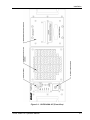
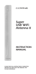
1
GLOBAL UNINTERRUPTIBLE POWER SUPPLY Model GUPS 2400A–107 Operation Manual Contact Information Telephone: 800 733 5427 (toll free in North America) 858 450 0085 (direct) Fax: 858 458 0267 Email: Domestic Sales: [email protected] International Sales: [email protected] Customer Service: [email protected] Web: www.programmablepower.com March 2011 Document No. M152491-01 Rev H . About AMETEK AMETEK Programmable Power, Inc., a Division of AMETEK, Inc., is a global leader in the design and manufacture of precision, programmable power supplies for R&D, test and measurement, process control, power bus simulation and power conditioning applications across diverse industrial segments. From bench top supplies to rack-mounted industrial power subsystems, AMETEK Programmable Power is the proud manufacturer of Elgar, Sorensen, California Instruments and Power Ten brand power supplies. AMETEK, Inc. is a leading global manufacturer of electronic instruments and electromechanical devices with annualized sales of $2.5 billion. The Company has over 11,000 colleagues working at more than 80 manufacturing facilities and more than 80 sales and service centers in the United States and around the world. Trademarks AMETEK is a registered trademark of AMETEK, Inc. Other trademarks, registered trademarks, and product names are the property of their respective owners and are used herein for identification purposes only. Notice of Copyright Global Uninterruptible Power Supply, Operation Manual © 2010 AMETEK Programmable Power, Inc. All rights reserved. Exclusion for Documentation UNLESS SPECIFICALLY AGREED TO IN WRITING, AMETEK PROGRAMMABLE POWER, INC. (“AMETEK”): (a) MAKES NO WARRANTY AS TO THE ACCURACY, SUFFICIENCY OR SUITABILITY OF ANY TECHNICAL OR OTHER INFORMATION PROVIDED IN ITS MANUALS OR OTHER DOCUMENTATION. (b) ASSUMES NO RESPONSIBILITY OR LIABILITY FOR LOSSES, DAMAGES, COSTS OR EXPENSES, WHETHER SPECIAL, DIRECT, INDIRECT, CONSEQUENTIAL OR INCIDENTAL, WHICH MIGHT ARISE OUT OF THE USE OF SUCH INFORMATION. THE USE OF ANY SUCH INFORMATION WILL BE ENTIRELY AT THE USER’S RISK, AND (c) REMINDS YOU THAT IF THIS MANUAL IS IN ANY LANGUAGE OTHER THAN ENGLISH, ALTHOUGH STEPS HAVE BEEN TAKEN TO MAINTAIN THE ACCURACY OF THE TRANSLATION, THE ACCURACY CANNOT BE GUARANTEED. APPROVED AMETEK CONTENT IS CONTAINED WITH THE ENGLISH LANGUAGE VERSION, WHICH IS POSTED AT WWW.PROGRAMMABLEPOWER.COM. Date and Revision March 2011 Revision H Part Number M152491-01 Contact Information Telephone: Fax: Email: Web: 800 733 5427 (toll free in North America) 858 450 0085 (direct) 858 458 0267 [email protected] [email protected] www.programmablepower.com i This page intentionally left blank. ii Important Safety Instructions Before applying power to the system, verify that your product is configured properly for your particular application. Hazardous voltages may be present when covers are removed. Qualified personnel must use extreme caution when servicing this equipment. Circuit boards, test points, and output voltages also may be floating above WARNING (below) chassis ground. The equipment used contains ESD sensitive ports. When installing equipment, follow ESD Safety Procedures. Electrostatic discharges might cause damage to the equipment. WARNING Only qualified personnel who deal with attendant hazards in power supplies, are allowed to perform installation and servicing. Ensure that the AC power line ground is connected properly to the Power Rack input connector or chassis. Similarly, other power ground lines including those to application and maintenance equipment must be grounded properly for both personnel and equipment safety. Always ensure that facility AC input power is de-energized prior to connecting or disconnecting any cable. In normal operation, the operator does not have access to hazardous voltages within the chassis. However, depending on the user’s application configuration, HIGH VOLTAGES HAZARDOUS TO HUMAN SAFETY may be normally generated on the output terminals. The customer/user must ensure that the output power lines are labeled properly as to the safety hazards and that any inadvertent contact with hazardous voltages is eliminated. Guard against risks of electrical shock during open cover checks by not touching any portion of the electrical circuits. Even when power is off, capacitors may retain an electrical charge. Use safety glasses during open cover checks to avoid personal injury by any sudden component failure. Neither AMETEK Programmable Power Inc., San Diego, California, USA, nor any of the subsidiary sales organizations can accept any responsibility for personnel, material or inconsequential injury, loss or damage that results from improper use of the equipment and accessories. SAFETY SYMBOLS iii Product Family: GUPS 2400A-107 Warranty Period: One Year WARRANTY TERMS AMETEK Programmable Power, Inc. (“AMETEK”), provides this written warranty covering the Product stated above, and if the Buyer discovers and notifies AMETEK in writing of any defect in material or workmanship within the applicable warranty period stated above, then AMETEK may, at its option: repair or replace the Product; or issue a credit note for the defective Product; or provide the Buyer with replacement parts for the Product. The Buyer will, at its expense, return the defective Product or parts thereof to AMETEK in accordance with the return procedure specified below. AMETEK will, at its expense, deliver the repaired or replaced Product or parts to the Buyer. Any warranty of AMETEK will not apply if the Buyer is in default under the Purchase Order Agreement or where the Product or any part thereof: is damaged by misuse, accident, negligence or failure to maintain the same as specified or required by AMETEK; is damaged by modifications, alterations or attachments thereto which are not authorized by AMETEK; is installed or operated contrary to the instructions of AMETEK; is opened, modified or disassembled in any way without AMETEK’s consent; or is used in combination with items, articles or materials not authorized by AMETEK. The Buyer may not assert any claim that the Products are not in conformity with any warranty until the Buyer has made all payments to AMETEK provided for in the Purchase Order Agreement. PRODUCT RETURN PROCEDURE 1. Request a Return Material Authorization (RMA) number from the repair facility (must be done in the country in which it was purchased): In the USA, contact the AMETEK Repair Department prior to the return of the product to AMETEK for repair: Telephone: 800-733-5427, ext. 2295 or ext. 2463 (toll free North America) 858-450-0085, ext. 2295 or ext. 2463 (direct) Outside the United States, contact the nearest Authorized Service Center (ASC). A full listing can be found either through your local distributor or our website, www.programmablepower.com, by clicking Support and going to the Service Centers tab. 2. When requesting an RMA, have the following information ready: Model number Serial number Description of the problem NOTE: Unauthorized returns will not be accepted and will be returned at the shipper’s expense. NOTE: A returned product found upon inspection by AMETEK, to be in specification is subject to an evaluation fee and applicable freight charges. iv CONTENTS SECTION 1 GENERAL DESCRIPTION ................................................ 1-1 1.1 Introduction .................................................................................................... 1-1 1.2 General Description........................................................................................ 1-1 1.3 Specifications ................................................................................................. 1-1 SECTION 2 INSTALLATION ............................................................... 2-1 2.1 Introduction .................................................................................................... 2-1 2.2 Unpacking and Inspection .............................................................................. 2-1 2.3 Installation ...................................................................................................... 2-2 2.4 Air Intake and Exhaust ................................................................................... 2-2 2.5 Input/Output Connectors ................................................................................ 2-2 2.6 Wire Gauge Selection .................................................................................... 2-6 SECTION 3 OPERATION ..................................................................... 3-1 3.1 Introduction .................................................................................................... 3-1 3.2 Control and Indicator Panel ............................................................................ 3-1 3.2.1 Indicators ............................................................................................ 3-1 3.2.2 Pushbutton Switches .......................................................................... 3-3 3.3 Circuit Breaker ............................................................................................... 3-3 3.4 Audible Alarm ................................................................................................. 3-3 3.5 Control Signals ............................................................................................... 3-3 3.6 Connectors ..................................................................................................... 3-4 3.7 Start-Up and Shutdown Sequences ............................................................... 3-5 3.8 Battery Operation ........................................................................................... 3-5 3.8.1 Battery Care and Handling ................................................................. 3-6 GUPS 2400A–107 Operation Manual v Contents 3.9 RS-232 Data Communications Port ................................................................3-7 3.9.1 Hardware Interface .............................................................................3-7 3.9.2 Software Interface ..............................................................................3-7 3.9.3 RS-232 Protocol .................................................................................3-8 3.9.4 Test Data Request Commands...........................................................3-8 3.9.5 Elgar Terminal Interface (ETI) Data Request Commands ...................3-10 3.9.6 Status Words ....................................................................................3-11 3.9.7 AC Line Loss Signal .........................................................................3-16 SECTION 4 MAINTENANCE ............................................................... 4-1 4.1 Introduction ....................................................................................................4-1 4.2 Service Information ........................................................................................4-1 4.3 Spare and Repair Parts ..................................................................................4-1 4.4 Periodic Maintenance .....................................................................................4-1 4.5 Troubleshooting ..............................................................................................4-2 LIST OF FIGURES Figure 2–1. GUPS 2400A-107 (Front View) ................................................................ 2-3 Figure 2–2. GUPS 2400A-107 (Rear View) ................................................................. 2-4 Figure 2–3. GUPS 2400A-107 Dimensions (Top, Side, and Front Views) ................... 2-5 Figure 3–1. GUPS 2400A-107 Control and Indicator Panel ....................................... 3-2 LIST OF TABLES Table 2–1. GUPS 2400A-107 Input/Output Connectors .............................................. 2-2 Table 2–2. Recommended Wire Gauge Selection Guide ............................................ 2-6 Table 3–1. GUPS 2400A-107 Connector Pin Assignments ......................................... 3-4 Table 3–2. Battery Storage Times............................................................................... 3-6 Table 3–3. RS-232 Connector Pin-Out........................................................................ 3-7 Table 3–4. RS-232 Communications Port Protocol ..................................................... 3-8 Table 3–5. Status Word 1 Data Format .................................................................... 3-11 Table 3–6. Status Word 2 Data Format .................................................................... 3-14 Table 4–1. GUPS 2400A-107 Troubleshooting Guide ................................................. 4-2 vi GUPS 2400A–107 Operation Manual SECTION 1 GENERAL DESCRIPTION 1.1 Introduction The Elgar Model GUPS 2400A-107 is a 2400 VA Global Uninterruptible Power Supply (GUPS) that provides regulated 115 VRMS, 60 Hz output power at up to 20.9 Amps RMS load current. The GUPS 2400A-107 accepts 3-phase AC input line voltages from 159V to 232V at frequencies from 370 Hz to 430 Hz. A battery backup of five minutes at 2400 VA output is provided by a removable battery pack. Output power is continuous when transferring from AC to battery or battery to AC. 1.2 General Description The GUPS 2400A-107 is contained in a rack-mount enclosure. All input and output connections are made at the rear panel. Cooling air is drawn in through a filter on the front panel and exhausted out the rear panel. Operational and input/output power status is indicated by front panel LEDs. An AC input circuit breaker and control pushbutton switches also are located on the front panel. There are no operator adjustments. 1.3 Specifications (Specifications Subject to Change Without Notice) AC Input Voltage: 115/200V, 3-phase, 3-wire plus ground, neutral not used; 159V to 232V, line voltage; 92V to 134V, phase voltage AC Input Current: 9.8A, maximum at 200V, 2400VA/1920W load, fully charged battery; 12.5A, maximum at 159V, 2400VA/1920W load, charging battery AC Input Frequency: 370Hz to 430Hz Batteries: 192VDC, sealed, maintenance-free, lead-acid Battery Hold-Up Time: 5 minutes with a 2400VA/1920W load at 25°C GUPS 2400A–107 Operation Manual 1-1 General Description Battery Recharge Time: 4 hours to 90% full charge following discharge at 2400VA/1920W and 25°C Output Voltage: 115V, ±2% Output Frequency: 60Hz, ±0.1% Output Current: 20.9A(RMS) Output Distortion: 2% THD, maximum with linear load Output Power: 1920W with resistive load; 2400VA/1920W with a reactive load or a non-linear load Efficiency: 77% AC to Battery Crossover: 159V, maximum low-line voltage; 232V, minimum high-line voltage Battery to AC Crossover: 169V, maximum low-line voltage; 232V, minimum high-line voltage AC Input Voltage Unbalance: 7V (RMS) maximum difference in line voltages Temperature: 0°C to 40°C (32°F to 104°F), operating; -40°C to 65°C (-40°F to 149°F), non-operating Humidity: 5% to 95% non-condensing, operating Altitude: 0 to 10,000ft, operating; 0 to 40,000ft, 2000ft/min, maximum, non-operating Dimensions: 7"H x 19"W x 25.1"D, excluding protrusion of handles, controls, and connectors; fits standard RETMA rack Weight: 75lb (34kg), UPS enclosure; 48lb (22kg) battery module; 123lb (56kg) total weight 1-2 GUPS 2400A–107 Operation Manual SECTION 2 INSTALLATION 2.1 Introduction The Elgar Model GUPS 2400A-107 has been aligned, calibrated, and tested prior to shipment. The instrument is ready for immediate use upon receipt. However, the following checks should be made to ensure that the instrument was not damaged during shipment. CAUTION! The GUPS 2400A-107 weighs 75 pounds (34 kg) without the battery pack. The battery pack adds an additional 48 pounds (22 kg). A minimum two–person lift is required! WARNING Hazardous voltages are present when operating this equipment. Please read the SAFETY NOTICE on page ii prior to installation, operation, or maintenance. 2.2 Unpacking and Inspection Perform a visual inspection of the shipping container prior to accepting the package from the carrier. If extensive damage is evident, a description of the damage should be noted on the carrier's receipt and signed by the driver of the carrier agent. If damage is not apparent until the instrument is unpacked, a claim for concealed damage should be placed with the carrier. Check for shipping damage such as dents, scratches, distortion, and damaged connectors. If the instrument or container(s) show signs of rough handling, remove the covers from the instrument to ensure that the circuit boards are securely in place and that no loose or broken components are evident. In addition, the shipping container(s) and filler material should be saved for inspection. Forward a report of damage to the Elgar Service Department. Elgar will provide instructions for repair or replacement of the instrument. GUPS 2400A–107 Operation Manual 2-1 Installation When returning the instrument to Elgar, suitable shipping containers and packing material must be used. If the instrument needs to be shipped and proper packing material is not available, contact Elgar to provide containers and shipping instructions. 2.3 Installation The Model GUPS 2400A-107 is 7" (178 mm) high and is designed to be installed in a standard 19" (483 mm) wide cabinet enclosure or a transit case. Refer to Figure 2–1 through Figure 2–3 for information on outline and mounting dimensions. 2.4 Air Intake and Exhaust The air intake is located on the front panel of the instrument and the exhaust is through the rear panel. Care must be taken not to block the air intake and exhaust. No special vertical separation is required when stacking instruments. However, a 1¾" (44.5 mm) vertical spacer above and below the instrument may improve cooling. CAUTION! Avoid blocking the instrument air intakes or exhaust. 2.5 Input/Output Connectors Table 2–1 provides a listing of the GUPS 2400A-107 input and output connectors. J1: AC Input Connector Panel Connector MS3102E20-4P Mating Connector MS3456W20-4S J2: AC Output Connector Panel Connector MS3102E20-19S Mating Connector MS3456W20-19P J3: Data/Alarm Port Connector Panel Connector MS3470W12-8S Mating Connector MS3476W12-8P Table 2–1. GUPS 2400A-107 Input/Output Connectors 2-2 GUPS 2400A–107 Operation Manual Installation Figure 2–1. GUPS 2400A-107 (Front View) GUPS 2400A–107 Operation Manual 2-3 Installation Figure 2–2. GUPS 2400A-107 (Rear View) 2-4 GUPS 2400A–107 Operation Manual Installation Figure 2–3. GUPS 2400A-107 Dimensions (Top, Side, and Front Views) GUPS 2400A–107 Operation Manual 2-5 Installation 2.6 Wire Gauge Selection The following guidelines assist in determining the optimum cable specification for the user's power applications. These guidelines are equally applicable to both DC and low frequency AC (up to 450 Hz) power cabling. The same engineering rules apply whether going into or out of an electrical device. Thus, this guide applies equally to the input cable and output cable for this Elgar instrument and application loads. Power cables must be able to safely carry maximum load current without overheating or causing insulation destruction. It is important to everyday performance to minimize IR (voltage drop) loss within the cable. These losses have a direct effect on the quality of power delivered to and from instruments and corresponding loads. When specifying wire gauge, the operating temperature needs to be considered. Wire gauge current capability and insulation performance drops with the increased temperature developed within a cable bundle and with increased environmental temperature. Thus, short cables with generously derated gauge and insulation properties are recommended for power source applications. Avoid using published commercial utility wiring codes. These codes are designed for the internal wiring of homes and buildings and accommodate the safety factors of wiring loss, heat, breakdown insulation, aging, etc. However, these codes consider that up to 5% voltage drop is acceptable. Such a loss directly detracts from the quality performance specifications of this instrument. Frequently, these codes do not consider bundles of wire within a cable arrangement. In high performance applications, as in motor start-up and associated inrush/ transient currents, additional consideration is required. The cable wire gauge must consider peak voltages and currents which may be up to ten times the average values. An underrated wire gauge adds losses which alter the inrush characteristics of the application and thus the expected performance. Table 2–2 identifies popular ratings for DC and AC power source cable wire gauges. Column 1 Size (AWG) 14 12 10 8 6 4 2 1/0 3/0 Column 2 Amperes (Maximum) 15 20 30 40 55 70 95 125 165 Column 3 Ohms/100 Feet (One Way) 0.257 0.162 0.102 0.064 0.043 0.025 0.015 0.010 0.006 Column 4 IR Drop/100 Feet (Col. 2 X Col. 3) 3.85 3.24 3.06 2.56 2.36 1.75 1.42 1.25 1.04 Table 2–2. Recommended Wire Gauge Selection Guide 2-6 GUPS 2400A–107 Operation Manual Installation The following notes apply to Table 2–2 and to the power cable definition: 1. The above figures are based upon insulated copper conductors at 25°C (77°F), two current carrying conductors in the cable plus a safety (chassis) ground. Columns 3 and 4 refer to "one way" ohms and IR drop of current carrying conductors (e.g., a 50-foot cable contains 100 feet of current carrying conductor). 2. Determine which wire gauge for the application by knowing the expected peak load current (Ipeak), the maximum tolerated voltage loss (Vloss) within the cable, and the one way cable length. The formula below determines which ohms/100 feet entry is required from Column 3. Read the corresponding wire gauge from Column 1. (Column 3 value) = Vloss/[Ipeak x 0.02 x (cable length)] Where: Column 3 value = Entry of the table above. Cable length = One way cable length in feet. Vloss = Maximum loss, in volts, permitted within cable. SPECIAL CASE: Should the Vloss requirement be very loose, Ipeak may exceed the maximum amperes (Column 2). In this case, the correct wire gauge is selected directly from the first two columns of the table. EXAMPLE: A 20 ampere (Ipeak) circuit which may have a maximum 0.5 volt drop (Vloss) along its 15foot cable (one way cable length) requires (by formula) a Column 3 resistance value of 0.083. This corresponds to wire gauge size 8 AWG. If the cable length was 10 feet, the Column 3 value would be 0.125 and the corresponding wire gauge would be 10 AWG. 3. Aluminum wire is not recommended due to soft metal migration at the terminals which may cause long term (on the order of years) poor connections and oxidation. If used, increase the wire gauge by two sizes (e.g., specify 10 gauge aluminum instead of 14 gauge aluminum). 4. Derate the above wire gauge (use a heavier gauge) for higher environmental temperatures since conductor resistance increases with temperature. Temperature °C °F Current Capability 40 80% 104 GUPS 2400A–107 Operation Manual 2-7 Installation 5. Derate the above wire gauge (use a heavier gauge) for an increased number of current carrying conductors. This offsets the thermal rise of bundled conductors. Number of Conductors Current Capability 3 to 6 80% Above 6 70% 6. The preferred insulation material is application dependent. Elgar recommends any flame retardant, heat resistant, moisture resistant thermoplastic insulation rated to a nominal 75°C (167°F). Voltage breakdown must exceed the combined effects of: • The rated output voltage; • Transient voltages induced onto the conductors from any source; • The differential voltage to other nearby conductors; and, • Safety margins to accommodate degradations due to age, mechanical abrasion and insulation migration caused by bending and temperature. 7. As frequency increases, the magnetic field of the current carrying conductors becomes more significant in terms of adverse coupling to adjacent electrical circuits. Use twisted pairs to help cancel these effects. Shielded twisted pairs are even better. Avoid close coupling with nearby cables by using separate cable runs for high power and low power cables. 8. The above general values and recommendations should be reviewed, modified and amended, as necessary, for each application. Cables should be marked with appropriate safety WARNING decals as hazardous voltages may be present. 2-8 GUPS 2400A–107 Operation Manual SECTION 3 OPERATION 3.1 Introduction This section provides detailed information on the controls and indicators, input/output connections, start-up and shutdown sequences, battery operation, and the RS-232 data communications port. 3.2 Control and Indicator Panel All controls and indicators for the GUPS 2400A-107 are located on the front panel of the unit. There are no operator adjustments inside the unit. Refer to Figure 3–1 for the location of the controls and indicators listed below. There are eight indicators and three pushbutton switches on the panel. In addition, there is an input circuit breaker located below the control panel. 3.2.1 Indicators AC INPUT Three green LED‘s that indicate the presence of line voltage at the AC input. The indicators turn on when the line voltage is greater than 90V (phase voltage greater than 52V). ON BATT An amber LED that indicates the loss of AC input and operation from battery power. BATT A three-color LED that indicates the condition of the battery. The LED is green under normal operating conditions, amber when the battery is discharging or has low capacity while charging, and red when the battery capacity is low and impending inverter shutdown is approached. LOAD A three-color LED that indicates the amount of output load. The LED is green when the load is less than 80% of maximum output, amber when the load is within 80% to 105%, and red when the load exceeds 105% (indicating that the inverter will shut down if the load is maintained). GUPS 2400A–107 Operation Manual 3-1 Operation TEMP A two-color LED that indicates an over-temperature condition within the GUPS. The LED is green under normal operating conditions and red when an over-temperature shutdown occurs. TEST A two-color LED that indicates the results of the internal self-test. The LED blinks while a selftest is in progress. When the test is complete, the LED turns green if the test is passed and red it the test is failed. Figure 3–1. GUPS 2400A-107 Control and Indicator Panel 3-2 GUPS 2400A–107 Operation Manual Operation 3.2.2 Pushbutton Switches OUTPUT ON A momentary pushbutton switch on the front panel that alternately turns the output power on and off. TEST A momentary push button switch on the front panel that initiates the internal self-test. ALARM SILENCE A momentary pushbutton switch on the front panel that silences the audible alarm. 3.3 Circuit Breaker The AC input breaker is located on the front panel below the Control and Indicator Panel. It is turned ON by pushing in the actuator button, and it is turned OFF by pulling out the actuator button. 3.4 Audible Alarm An audible alarm is sounded for the following alarm conditions: loss of AC input; low battery voltage; over-temperature. If the audible alarm is silenced and an alarm condition is again present, the audible alarm will again be sounded. 3.5 Control Signals The Data/Alarm Port provides an interface to remote alarms or a host computer. The control signals provide annunciation of the mode of operation, control of the system shutdown, and RS232 data communications. The control signals of the Data/Alarm Port and their signal return could be floated up to 80VPK above chassis ground. AC FAIL Normally-open relay contacts that close when the AC input is outside the allowed range for voltage or phase unbalance. LOW BATTERY Normally-open relay contacts that close when the battery voltage approaches the shutdown threshold for the inverter. SHUTDOWN Input to a relay coil whose contacts interface with the control circuits of the GUPS. Energizing the relay with a DC voltage, 16.8-36VDC (1,070 ±10% coil resistance), will result in shutdown. If SHUTDOWN is asserted while the AC input is present, the output relay will open and output power will be turned off; the inverter and control circuits will continue to operate. GUPS 2400A–107 Operation Manual 3-3 Operation If SHUTDOWN is asserted while the AC input is not present and the inverter is running from the battery, the output relay will open and output power will be turned off; the inverter and control circuits will also be shut down. After shutdown, the OUTPUT ON switch must be manually toggled to turn the output back on. RS-232 TRANSMIT/RECEIVE RS-232 transmit and receive for data communications. Refer to Section 3.9 for more information on RS-232 interface. OUTPUT CURRENT An AC voltage signal that is proportional to the AC output current. The output is 0.221V/A, or 4.6 VRMS at full load. This signal is transformer isolated from the other control signals. 3.6 Connectors The GUPS 2400A-107 has cylindrical, metal-shell connectors with bayonet coupling for all input/output connections of power and signal. All connectors are located on the rear panel. Pin assignments are listed in Table 3–1. Connector Pin Assignment Connector J1, AC INPUT Pin A: Phase A Pin B: Phase B Pin C: Phase C Pin D: Chassis Ground (Neutral not used) Connector J2, AC OUTPUT Pin A: Line Pin B: Neutral (internally connected to chassis) Pin C: Chassis Ground Connector J3, DATA/ALARM PORT Pin A: AC FAIL normally-open relay contact Pin B: LOW BATTERY normally-open relay contact Pin C: SHUTDOWN input for remote shutdown Pin D: RS-232 TRANSMIT signal (output) Pin E: RS-232 RECEIVE signal (input) Pin F: SIGNAL RETURN for signals on Pins A-E Pin G: OUTPUT CURRENT sense signal Pin H: Return for OUTPUT CURRENT sense signal GROUND STUD #10-32 Stud: Earth Ground Table 3–1. GUPS 2400A-107 Connector Pin Assignments 3-4 GUPS 2400A–107 Operation Manual Operation 3.7 Start-Up and Shutdown Sequences To run the GUPS 2400A-107 from an AC input, perform the following steps: 1. Turn on the AC input circuit breaker located on the front panel. 2. Wait approximately 10 seconds for completion of the start-up routines. During this time, the GUPS performs a self-test to assure proper functionality, and the rectifier undergoes a soft-start so that current surges on the AC input are prevented. 3. After the start-up delay, the inverter will turn on (fan will be energized), but the output will be off. Also, the charger will be on to charge the internal battery. 4. To turn ON the output, press the OUTPUT ON switch. The output relay will close and connect the inverter to the load. The inverter will momentarily turn off prior to closing of the output relay to prevent switching load current with the relay. If the AC input voltage exceeds the allowed range, the unit will draw power from the internal battery and continue to run until the battery is depleted. If the AC input returns to the allowed range, and low battery shutdown of the inverter has not yet occurred, the unit will again draw power from the AC input and also recharge the battery with the battery charger. 5. To turn OFF the output, press the OUTPUT ON switch again; the switch has a alternating ON/OFF action. The inverter will momentarily turn off and the output relay will open. The inverter will again turn on after the relay is open. The inverter is turned off while the relay is opening to prevent switching load current with the relay. If the AC input voltage exceeds the allowed range while the output is turned off, the unit will shut down; the inverter, charger, and all control circuits will be turned off. 3.8 Battery Operation To run the GUPS 2400A-107 from battery when an AC input is not present or outside the allowed operating range, perform the following: 1. The AC input circuit breaker located on the front panel could be either in the on or off positions. 2. To turn ON the output, press the OUTPUT ON switch. After a short delay, the output relay will close and the inverter will start, supplying power to the load. The unit will run until the battery is depleted. If the AC input returns to the allowed range, and the AC input breaker is closed, power will be drawn from the AC input and the battery charger will recharge the battery. CAUTION! If the battery module is not inserted when the unit is started, all front panel LED’s will indicate RED, and the unit will not operate. GUPS 2400A–107 Operation Manual 3-5 Operation 3. 3.8.1 To turn OFF the output, press the OUTPUT ON switch again; the switch has a alternating ON/OFF action. The unit will shut down (with no AC input present); the inverter and all control circuits will turn off. Battery Care and Handling The battery used in the GUPS 2400A-107 requires proper storage and recharging to maintain reliability. During storage, the self-discharge of the battery results in a sulfate coating that builds up on the plates. This coating reduces the effective surface area of the plates which reduces the available backup time. Allowing the batteries to self-discharge for too long may result in recharging problems or in battery degradation. Storing the battery at low temperatures reduces the level of chemical activity, thus sulphation takes longer to occur. Reasonable storage times at different temperatures are listed in Table 3–2. Storage Temperature Storage Time 0°C (32°F) 20 Months 10°C (50°F) 10 Months 20°C (68°F) 5 Months 40°C (104°F) 1½ Months Table 3–2. Battery Storage Times The batteries should be recharged for 72 hours after prolonged storage. CAUTION! Failure to recharge the batteries after the storage time may result in permanent battery degradation. 3-6 GUPS 2400A–107 Operation Manual Operation 3.9 RS-232 Data Communications Port The RS-232 data communications port provides an interface between a data terminal (or a computer emulating a data terminal) and the GUPS 2400A-107. It allows transfer of information such as parameter values, mode of operation, and alarm conditions. 3.9.1 Hardware Interface Interface signals for communication to and from the GUPS 2400A-107 are provided via a connector (MS3470W12-8S) located on the rear panel of the unit. The RS-232 interface connector is designated as J3, DATA/ALARM PORT. The J3 connector pin-out for the RS-232 interface is given in Table 3–3. Pin Number Signal D Transmit from the GUPS E Receive to the GUPS F Signal Ground Table 3–3. RS-232 Connector Pin-Out 3.9.2 Software Interface The RS-232 interface firmware in the GUPS 2400A-107 has the following communication features: Two sets of remote terminal software commands Text data request commands, which are applicable for dumb terminal display of the unit status. Text data request commands return both descriptive text and the data values requested Fast ―data only‖ data request commands called the Elgar Terminal Interface (ETI), for use by a program running on a host computer. The ETI commands return only the data values that are requested Data available via the RS-232 interface includes AC Line Loss signal AC Input voltage in floating point or hexadecimal AC output voltage in floating point or hexadecimal AC output current in floating point or hexadecimal Battery/Charger DC voltage in floating point or hexadecimal Impending shutdown annunciation GUPS 2400A–107 Operation Manual 3-7 Operation 3.9.3 RS-232 Protocol The GUPS 2400A-107 RS-232 communications port protocol is given in Table 3–4. Baud Rate 9600 Data Bits 8 Start Bits 1 Stop Bits 1 Parity None Table 3–4. RS-232 Communications Port Protocol 3.9.4 Test Data Request Commands The GUPS 2400A-107 RS-232 text data mode commands have been developed for a user interface utilizing a dumb terminal interface. The text data mode commands provide formatted responses that include both the name of data parameters and the measured values. Each of the text data requests supported by the GUPS 2400A-107 is described below. 3.9.4.1 List Selection Menu Enter a ―space‖ (0x20) character to view the following menu: k = Display calibration constants l = ETI calibration m = ETI A/D n = ETI Float s = Status registers v = Display version 3-8 GUPS 2400A–107 Operation Manual Operation 3.9.4.2 Display Calibration Values Enter a command ‗k‘ (lowercase K) character to display the calibration constants for the A/D converter algorithms values. For example: Calibration Constants: 80 percent current: 32F8 105 percent current: 424B 150 percent current: 50E7 Minimum voltage band: 2000 Maximum voltage band: 2100 Battery 200 volts: 0198 Battery bad: 0240 Battery shutdown: 0268 AC line A-B scale factor: 31030 AC line B-C scale factor: 31030 AC line C-A scale factor: 31030 Vout rdbk cal: 91.3 Vout rdbk dvm: 114.5 3.9.4.3 // Output current in hexadecimal // Output voltage in hexadecimal // Battery voltage in hexadecimal // AC input line voltage scale factors in decimal // Output voltage readback calibration in floating point format Display Status Registers and A/D Values Enter a command ‗s‘ (lowercase S) character to display the two 16-bit status registers, along with the A/D values of the AC input voltage, Output voltage, Output current, and Battery/Charger voltage. For example: Status word 1: 5540 Status word 2: 0283 A/D Values: Output Voltage: 115.0 Output Current: 3.25 Input Voltage A-B: 200.0 Input Voltage B-C: 200.0 Input Voltage C-A: 200.0 Battery Voltage: 190.00 // 16-bit status flags in hexadecimal // A/D values in floating point and hexadecimal 2314 0028 4E20 4E20 4E20 0284 The status word formats are explained in Section 3.9.6. 3.9.4.4 Display Firmware Version Number Enter a command ‗v‘ (lowercase V) character to display the version number of the firmware. For example: Firmware version number: P/N 5152457-01, Rev 2.0 GUPS 2400A–107 Operation Manual 3-9 Operation 3.9.5 Elgar Terminal Interface (ETI) Data Request Commands The GUPS 2400A-107 RS-232 text data mode commands have been developed for use by a program running on a host computer. The ETI mode data request commands provide formatted responses of only the measured value data in a formatted form. Each of the ETI data request commands supported by the GUPS 2400A-107 is described below. 3.9.5.1 Provide Calibration Values Enter a command ‗l‘ (lowercase L) character to obtain the calibration constants for the A/D converter algorithms values. For example, this command will return the GUPS 2400A-107 calibration constants in the following order: Output Current at 80% Output Current at 105% Output Current at 150% Minimum Output Voltage Maximum Output Voltage Battery Good Voltage Battery Bad Voltage Battery Shutdown Voltage Output Voltage Measurement Output Voltage Measurement 3.9.5.2 // current calibration in hexadecimal // voltage calibration in hexadecimal // battery voltage in hexadecimal // scale factor in floating point Provide Status Words and Hexadecimal A/D Values Enter a command ‗m‘ (lowercase M) character to obtain the Status Words and hexadecimal A/D calibration constants for the A/D converter algorithms values. For example, this command will return the A/D values and the unit status in the following order: Status word 1 Status word 2 Output Voltage Output Current AC Input Voltage Line A-B AC Input Voltage Line B-C AC Input Voltage Line C-A Battery/Charger Voltage // 16-bit status flags in hexadecimal // A/D values in hexadecimal The status word formats are explained in Section 3.9.6. 3.9.5.3 Provide Status Words and Floating Point A/D Values Enter a command ‗n‘ (lowercase N) character to obtain the Status Words and floating point A/D calibration constants for the A/D converter algorithms values. This command will return the A/D values and the unit status as in the ‗m‘ command, but the voltages and currents will be returned in IEEE floating point format. 3-10 GUPS 2400A–107 Operation Manual Operation 3.9.6 Status Words The status words may be used to examine the current state of the GUPS 2400A-107, but are not meant to be used in applications that are time–critical such as AC line loss detection. The ―Line Loss Detected‖ message sent from the GUPS 2400A-107 (refer to Section 3.9.7), or the AC Line Loss signal (relay contact closure) will have the quickest response time. 3.9.6.1 Status Word 1 Format Table 3–5 provides the bit position information and definition of the data in Status Word 1. Bit Name 0 Over Temperature 1 Alarm Sense 2 Alarm Silence 3 Charger Status 4 Current Overload 5 Battery Switch 6 Test Mode 7 Inverter Status 8 Output Relay 9 Impending Shutdown 10 Rectifier Slow Start 11 Equalization Charge 12 Power Available 13 PWM Soft Start 14 Reserved 15 Battery Slow Start Definition 0 = Normal Operation 1 = Over Temperature 0 = Alarm Not Sensed 1 = Alarm Sensed 0 = Alarm Silence Not Enabled 1 = Alarm Silence Enabled 0 = Charger Not On 1 = Charger On 0 = Normal Operation 1 = Current Overload 0 = Battery Switch Not On 1 = Battery Switch On 0 = Normal Operation 1 = Test Mode 0 = Inverter Not On 1 = Inverter On 0 = Output Relay Open 1 = Output Relay Closed 0 = Greater then 1 minute 1 = Less then 1 minute 0 = Normal Operation 1 = Rectifier In Slow Start 0 = Equalization Charge Not On 1= Equalization Charge On 0 = Power Not Available 1 = Power Available 0 = Normal Operation 1 = Unit In Soft Start Mode — 0 = Normal Operation 1 = Battery Slow Start Table 3–5. Status Word 1 Data Format GUPS 2400A–107 Operation Manual 3-11 Operation 3.9.6.2 Status Word 1 Status Bit Condition Definitions The definitions of the conditions and usage of the bits in Status Word 1 are defined below. Over Temperature (Status Word 1, Bit 0) The Over Temperature status bit indicates that the thermostat internal to the GUPS 2400A-107 has exceeded its trip point. A binary value of 0 indicates normal operation, while a binary value 1 indicates that the thermostat sensor has exceeded its trip point value of 95ºC. Alarm Sense (Status Word 1, Bit 1) The Alarm Sense bit indicates that an alarm condition is currently being detected by the unit. A binary value of 0 indicates that no alarms are being sensed, while a binary value of 1 indicates that an alarm is being sensed. Alarm Silence (Status Word 1, Bit 2) The Alarm Silence bit reflects the setting of the front panel Alarm Silence button of the GUPS 2400A-107. A binary value of 0 indicates that the Alarm Silence is Not Enabled (when an alarm condition is sensed the audible alarm will annunciate it), while a binary value of 1 indicates that the Alarm Silence is Enabled (a subsequent change in the alarm condition will re-enable the alarm). Charger Status (Status Word 1, Bit 3) The Charger Status bit reflects the condition of the charger enabled logic of the GUPS 2400A-107. A binary value of 0 indicates that the charger is not on, while a binary value of 1 indicates that the charger is on. Current Overload (Status Word 1, Bit 4) The Current Overload bit indicates that the unit has sensed a current overload of greater than 105% of the specified output current. A binary value of 0 indicates normal operation, while a binary value of 1 indicates that the output current is greater than 105% of the specified current output capability of the unit. Battery Switch (Status Word 1, Bit 5) The Battery Switch bit reflects the status of the SCR battery switch in the GUPS 2400A-107 which connects the battery to the internal DC bus. A binary value of 0 indicates that the battery switch is not on, while a binary value of 1 indicates that the battery switch is on. Test Mode (Status Word 1, Bit 6) The Test Mode status bit indicates if the GUPS 2400A-107 is in test mode. A binary value of 0 indicates that the unit is in normal operating mode, while a binary value of 1 indicates that the unit is in test mode (as commanded by the execute test mode button on the front panel of the GUPS 2400A-107). Inverter Status (Status Word 1, Bit 7) The Inverter Status bit indicates the operating condition of the output inverter of the GUPS 2400A-107. A binary value of 0 indicates that the output inverter is not on, while a binary value of 1 indicates that the inverter is on. 3-12 GUPS 2400A–107 Operation Manual Operation Output Relay (Status Word 1, Bit 8) The Output Relay status bit indicates the state of the units output relay. A binary value of 0 indicates that the units output relay is open, while a binary value of 1 indicates that the output relay is closed. Impending Shutdown (Status Word 1, Bit 9) The Impending Shutdown status bit indicates the status of the battery of the unit. A binary value of 0 indicates more than 1 minute of back-up time is available or that the battery voltage is greater than 177 volts, while a binary value of 1 indicates that less then 1 minute of back-up time is available or that the battery voltage that is less than 177 volts. Rectifier Slow Start (Status Word 1, Bit 10) The Rectifier Slow Start status bit indicates that the unit is in rectifier slow start mode. A binary value of 0 indicates that the unit is in normal operating mode, while a binary value of 1 indicates that the unit is in rectifier slow start mode. Equalization Charge (Status Word 1, Bit 11) The Equalization Charge status bit indicates that the unit is in equalization charge enable mode. A binary value of 0 indicates that the unit is normal operating mode, while a binary value of 1 indicates that the unit is in equalization charge mode. Power Available (Status Word 1, Bit 12) The Power Available status bit indicates that power is available to the unit either from the AC input or the battery. A binary value of 0 indicates that power is not available, while a binary value of 1 indicates that power is available. PWM Soft Start (Status Word 1, Bit 13) The PWM Soft Start status bit indicates that the unit is in PWM soft start mode. A binary value of 0 indicates that the unit is in normal operating mode, while a binary value of 1 indicates that the unit is in soft start mode. Status Word 1, Bit 14 Reserved Battery Slow Start (Status Word 1, Bit 15) The Battery Slow Start status bit indicates the unit is in battery slow start mode. A binary value of 0 indicates that the unit is in normal operating mode, while a binary value of 1 indicates that the unit is in battery slow start mode. GUPS 2400A–107 Operation Manual 3-13 Operation 3.9.6.3 Status Word 2 Format Table 3–6 provides the bit position information and definition of the data in Status Word 2. Bit Name 0 Running on Battery 1 Reserved 2 Inverter Keypress 3 System Shutdown 4 Reserved 5 Running on AC Line 6 150% Overload Sense 7 Float Timer Time-out 8 Wait to equalize 9 Pass/Fail System Self-Test 10 System Down 11 AC Input Line Out of Range 12 Delayed Event Flag 13 14 Reserved Reserved 15 Improper Output Voltage Definition 0 = Running on AC 1 = Running on battery 0 = No Keypress Pending 1 = Inverter Keypress Pending 0 = System Operating 1 = System Shutdown — 0 = Running on Battery 1 = Running on AC Line 0 = Normal Operation 1 = 150% Overload Detected 0 = Not Float Charging 1 = Float Timer Time-out 0 = No Equalization Pending 1 = Waiting To Equalize 0 = Self Test Failed 1 = Self Test Passed 0 = System Operational 1 = System Is Shutting Down 0 = AC Input Line In Range 1 = AC Input Line Out of Range 0 = No Pending Delayed Events 1 = Delayed Event Pending — — 0 = Output Normal 1 = Output Is Low Table 3–6. Status Word 2 Data Format 3-14 GUPS 2400A–107 Operation Manual Operation 3.9.6.4 Status Word 2 Status Bit Condition Definitions The definitions of the conditions and usage of the bits in Status Word 2 are defined below. Running on Battery (Status Word 2, Bit 0) The Running on Battery status bit indicates that the unit is operating on batteries. A binary value of 0 indicates that the unit is running on AC input, while a binary value of 1 indicates that the unit is running on battery. Status Word 2, Bit 1 Reserved. Inverter Keypress (Status Word 2, Bit 2) The Inverter Keypress status bit indicates that a front panel keypress has occurred. A binary value of 0 indicates that no key presses are pending, while a binary value of 1 indicates that a keypress has occurred. System Shutdown (Status Word 2, Bit 3) The System Shutdown status bit indicates that the system has been commanded to shut down, and a system shutdown is in effect. A binary value of 0 indicates that the system is operating (normal operating mode), while a binary value of 1 indicates that the unit is in system shutdown mode. Status Word 2, Bit 4 Reserved. Running on AC Line (Status Word 2, Bit 5) The Running on Line status bit indicates that the unit is operating on the AC input. A binary value of 0 indicates that the unit is running on battery input, while a binary value of 1 indicates that the unit is running on the AC input. 150% Overload Sense (Status Word 2, Bit 6) The 150% Current Overload bit indicates that the unit has sensed a current overload of greater than 150% of the specified output current. A binary value of 0 indicates normal operation, while a binary value of 1 indicates that the output current is greater than 150% of the specified current output capability of the unit. Float Timer Time-out (Status Word 2, Bit 7) The Float Timer Time-out status bit indicates the condition of the units float timer function. A binary value of 0 indicates that the timer has not timed out, while a binary value of 1 indicates that the unit‘s float timer has timed-out. Wait to Equalize (Status Word 2, Bit 8) The Wait to Equalize status bit indicates if the unit is waiting to equalize the batteries. A binary value of 0 indicates that the unit has no equalization pending, while a binary value of 1 indicates that the unit is waiting to equalize the batteries. GUPS 2400A–107 Operation Manual 3-15 Operation Pass/Fail System Self-Test (Status Word 2, Bit 9) The Pass/Fail System Self-Test status bit indicates the results of the last run system self test. A binary value of 1 indicates that the unit passed the last self-test, while a binary value of 0 indicates that the unit failed the last self-test. System Down (Status Word 2, Bit 10) The System Down status bit indicates that the unit is in shutdown mode. A binary value of 0 indicates that the unit is operational, while a binary value of 1 indicates that the system is in shutdown mode. AC Input Line (Status Word 2, Bit 11) The AC Input Line status bit indicates the condition of the AC input line. A binary value of 0 indicates that the AC input line is within the specified input range, while a binary value of 1 is not within the specified input range. Delayed Event Flag (Status Word 2, Bit 12) The Delayed Event Flag status bit indicates the status of pending delayed events. A binary value of 0 indicates that the unit has no pending delayed events, while a binary value of 1 indicates that unit has at least one delayed event pending. Status Word 2, Bit 13 Reserved. Status Word 2, Bit 14 Reserved. Improper Output Voltage (Status Word 2, Bit 15) The Improper Output status bit indicates that the unit has sensed a sustained low voltage condition on the output. A binary value of 0 indicates that the output is normal, while a binary value of 1 indicates that the output voltage has dropped to less than 80 % of its nominal value. 3.9.7 AC Line Loss Signal When the AC line is lost, the GUPS 2400A-107 will send the message ―Line Loss Detected‖ out the RS-232 port. Applications may use this as a trigger to take action on a host computer. 3-16 GUPS 2400A–107 Operation Manual SECTION 4 MAINTENANCE 4.1 Introduction This section contains general information about maintenance of the GUPS 2400A-107. There are no adjustments accessible to the user. WARNING Hazardous voltages are present when operating this equipment. Please read the SAFETY NOTICE on page Error! Bookmark not defined. prior to installation, operation, or maintenance. 4.2 Service Information Questions concerning the operation, repair or service of this instrument should be directed to the nearest Elgar representative or to the Elgar Service Department, Elgar Electronics Corporation, 9250 Brown Deer Road, San Diego, CA 92121-2294. Include the model number and serial number in any correspondence concerning this instrument. DO NOT return the unit to the factory without prior authorization. 4.3 Spare and Repair Parts When ordering spare parts or repair parts, specify the part name, part number, component value and rating, and the Elgar part number, if available. If complete assemblies are required, contact the Elgar Service Department. Specify the assembly part number as marked on the assembly and the unit model number, GUPS 2400A-107, when ordering. 4.4 Periodic Maintenance The only maintenance required for this instrument is to periodically remove and clean or replace the front panel fan filter. The amount of time between cleaning is dependent on the environment in which the unit is used. Dust and dirt accumulation in the air filter can cause restricted air flow and subsequent overheating or reduced life on the internal components and batteries. GUPS 2400A–107 Operation Manual 4-1 Maintenance 4.5 Troubleshooting In the event that a problem arises during unit operation, refer to the guidelines listed in Table 4–1 to assist in determining the cause and to repair the unit as quickly as possible. Symptom Probable Cause Suggested Solution No indicators are illuminated. The AC line voltage is not present. Energize the input circuit breaker; press the OUTPUT ON pushbutton. All indicators are illuminated red. The battery module is unplugged. Open the input circuit breaker, unplug the battery module, then re-insert the battery module into the connector. AC is not present on the output. The output relay is not closed. Press the OUTPUT ON pushbutton. The ON BATT indicator is illuminated amber. The AC input is either below 169V or is above 232V. Ensure the AC line is within the proper operating range. The TEMP indicator is illuminated red. The filter is clogged. Clean the filter, if required. The BATTERY indicator is illuminated red. 1) Low battery voltage or 2) a defective battery. 1) Recharge the battery or 2) replace the battery, as required. The inverter transfers to battery then quickly shuts down. 1) The batteries are discharged; 2) the batteries are sulfated; or 3) the output relay is open. 1) Allow a 4-hour recharge of the batteries; 2) allow a 72-hour recharge of the batteries; or 3) press the OUTPUT ON pushbutton, as required. The LOAD indicator is illuminated red. There is an overload on the output. Reduce the load. The LOAD indicator is not illuminated. The output relay is open. Press the OUTPUT ON pushbutton to close the output relay. The TEST indicator is blinking. The TEST pushbutton has been pressed. Wait until the self-test is complete before operating any other controls. The TEST indicator does The output relay is closed. not blink when the TEST pushbutton is pressed. TEST will only be performed if the relay is open. Table 4–1. GUPS 2400A-107 Troubleshooting Guide 4-2 GUPS 2400A–107 Operation Manual