1
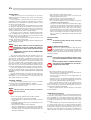
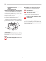
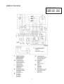
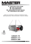
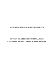
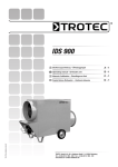
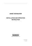
SPACE HEATERS
JUMBO
INSTRUCTIONS MANUAL
Ed. 06/08
MANUFACTURER
BIEMMEDUE S.p.A.
Via Industria, 12
12062 Cherasco (CN) - ITALIA
Tel. +39 0172 486111 - Fax +39 0172 488270
www.biemmedue.com - e-mail: [email protected]
MODEL
JUMBO 65 M, 65 T, 90 M, 90 T, 90 M/C, 115 M, 115 T, 115 M/C, 115 T/C
JUMBO 150 M, 150 T, 150 M/C, 150 T/C, 200 M, 200T, 200 T/C
Before using the heater, read and understand all instructions and follow them carefully.
The manufacturer is not responsible for damages to goods or persons due to improper use of units.
il.
Ed. 06/08
GENERAL HAZARD WARNING
FAILURE TO COMPLY WITH THE PRECAUTION AND INSTRUCTIONS PROVIDED WITH THIS HEATER, CAN RESULT IN DEATH, SERIOUS INJURY AND PROPERTY LOSS OR DAMAGE FROM HAZARD OF FIRE, EXPLOSION, BURN, ASPHYXIATION, CARBON MONOXIDE POISONING, AND
/ OR ELECTRICAL SHOCK.
ONLY PERSONS WHO CAN UNDERSTAND AND FOLLOW THE INSTRUCTIONS SHOULD USE OR SERVICE THIS HEATER.
IF YOU NEED ASSISTANCE OR HEATER INFORMATION SUCH AS AN INSTRUCTIONS MANUAL, LABEL, ETC., CONTACT THE MANUFACTURER.
WARNING: FIRE, BURN, INHALATION AND EXPLOSION HAZARD
KEEP SOLID COMBUSTIBLES, SUCH AS BUILDING MATERIALS, PAPER OR CARDBOARD, A SAFE DISTANCE AWAY FROM THE
HEATER AS RECOMMENDED BY THE INSTRUCTIONS.
NEVER USE THE HEATER IN SPACES WHICH DO OR MAY CONTAIN VOLATILE O AIRBORNE COMBUSTIBLES, OR PRODUCTS
SUCH AS GASOLINE, SOLVENTS, PAINT THINNER, DUST PARTICLES OR UNKNOWN CHEMICALS.
WARNING
NOT FOR HOME OR RECREATIONAL VEHICLE USE.
2
CONTROL BOARD - TABLEAU DE COMMANDE
L1
6
4
L2
5
F
7
1
CONTROL LAMP
2
CONTROL KNOB HEAT - STOP - VENTILATION ONLY
3
POWER CORD FASTENER
4
OVERHEAT SAFETY THERMOSTAT, L1
5
FAN THERMOSTAT, F
6
LIMIT THERMOSTAT WITH MANUAL RESTART, L2
7
THERMOSTAT RESET SWITCH
8
HOUR COUNTER
9
OVERHEAT THERMOSTATS CONTROL LAMP, L1, L2
10 FAN STOP CONTROL LAMP
11
11 HEATED DIESEL FILTER PLUG
12 BURNER PLUG
2
0
h
0000000
8
13 ROOM THERMOSTAT PLUG
9
1
13
10
12
3
3
EN
DESCRIPTION
• Don’t let animals or children near the heater.
• Make sure heater is inspected before each use, and at least annually bya qualified service person.
• After use make sure the disconnecting switch is off.
When using any type of space heater it is obligatory:
• not to exceed the maximum level of heat output of the furnace
(“TECHNICAL SPECIFICATION TABLE”);
• to make sure that there is adequate air circulation and air supply
to the heater and that nothing is obstructing the aspiration and
expulsion of air; movement of air may be obstructed in various
ways including placing covers or other objects on the heater or
positioning the heater too near a wall or other large object. If the
airflow is not adequate, the combustion chamber will overheat
and the overheat safety thermostat L1 will turn the burner off
and on continnously (“OBSERVED FAULTS, CAUSES AND
REMEDIES”).
JUMBO space heaters have been designed for use in small to
medium-sized rooms and buildings where a fixed or mobile heating
system is required.
Heat is produced by combustion and the heat from the smoke is
transmitted to the fresh air through the metal walls of the combustion
chamber and the heat exchanger. The combustion chamber is of the
type where smoke circulates twice.
The air and smoke pass through separated ducts, both of which
are welded and sealed. When, after combustion, the waste gases have
cooled, they are expelled through a duct which must be connected to a
chimney or chimney flue. The chimney or chimney flue must be big
enough to guarantee that the smoke is expelled efficiently.
The air which is used in combustion is aspirated directly from the
room or building which is being heated. It is therefore of utmost importance that the room or building be properly ventilated so that
enough fresh air is circulating at all times.
The air outlet can be replaced by outlet panels with two or four
openings, all of which must be kept open.
Jumbo heaters can operate with burners that are fuelled by diesel oil
#2 max., natural gas or propane.
INSTALLATION
Warning
The following operations must be carried out by qualified personnel only.
Warning
Only the burners which are chosen and supplied by the
manufacturer can be used. If another type of burner is
used the heater no longer complies with CSA / UL regulations.
Applied burners are listed in the final “TECHNICAL CHARACTERISTICS” sheet
ELECTRICAL CONNECTIONS AND SETTINGS
Every space heater is supplied along with the safety and control
devices which are indispensable to the correct functioning of the unit.
The electric switchboard, burner, the fan thermostat, overheat safety
thermostat and the overheat thermostat with manual restart have already been connected.
There are three safety devices which are activated in case of serious malfunction. The Burner Control Device, which is mounted on the
burner and has a restart button, automatically stops the burner if the
flame goes out. The Overhrat Thermostat, L2, of the manuel restart
type, is activated if the temperature of the combustion chamber rises
above the set maximum limit; the warning light (9) lights up and the
heater stops working. The Thermal Relay,RM, is activated if the fan
motor starts to use more electrical current than the maximum permitted limit; the warning light (10) lights up and the heater stops working.
If any of these safety devices are activated you should check carefully what the problem actually is before pressing the restart button
and starting the heater off again (“OBSERVED FAULTS, CAUSES AND
REMEDIES”).
Overheat safety thermostat, L1, shuts down the heater if air flow is
not sufficient to cool off combustion chamber: the heater will restart
automatically as soon as the heater has cooled down enough (The
lamp (9) lights up and then it cuts down).
Warning
Power supply cord of proper dimension shall be connected to the main switchboard and heater shall be grounded.
Electrical grounding shall be in compliance with the National Electrical Code ANSI/NFPA 70 or the CSA C22.1
Canadian Electrical Code, Part I.
The following operations must now be carried out:
• Plug in the power cord having read the adhesive label which details electricity supply characteristics.
• The burner must be connected to the fuel supply (Burner Instruction Manual).
• Connect the burner to the electricity supply with the burner plug.
• Connect accessories such as the room thermostat or clock to the
unit’s electric switchboard with the thermostat plug.
Having completed all these operations check carefully that all
electrical connections correspond to the wiring diagram. When the
heater is first turned on you must check that the fan does not use more
current than the maximum permitted limit.
Finally, to regulate the burner follow the instructions in the Burner
Instruction Manual.
GENERAL ADVICES
The heater is designed and approved for use as a construction
heater in accordance with Standard ANSI Z83.7 - CGA 2.14.
Intended use is the temporary heating of buildings or structures
under construction, alteration or repair.
Warning
CHECK
WITH YOUR LOCAL FIRE SAFETY AUTHORITY IF YOU HAVE QUES-
TIONS ABOUT APPLICATIONS.
CONNECTION TO HOT AIR DUCTS
The space heater provides heat by releasing and dispersing hot air.
An air head is supplied with each unit but it can be replaced by other
types of head with two or four openings which allow for flexible tubes
in heat distribution. The screws which hold the original outlet in place
should be removed and the new outlet should be screwed on in place
of the old.
The new head may be connected to new air ducts if the user wishes to satisfy specific needs. In this case and in particular if the diameter and length of the ducts have been changed or if the number of
bends has been modified, air output may vary. Consequently it is very
important to check and regulate air output when any modification is
made to air heads or air ducts. In all circumstances you must ensure
Here are a few general guidelines which should be followed:
• Follow the instructions in this booklet very carefully.
• Don’t install the heater in places where there may be a risk of fire
or explosion.
• Inflammable material should be kept at a safe distance from the
heater (Minimum 6 feet).
• All fire prevention regulations must be adhered to.
• The room or building which is being heated must be sufficiently
ventilated so that the heater has enough air to function properly.
• The heater must be near a chimney or chimney flue and a suitable electric switchboard.
4
EN
used, burners shall be adapted according to the instruction manual of
the burner.
In case of connection of heater to natural gas,the installation shall
conform with local codes, or, in the absence of local code, with the National Fuel Gas Code ANSI Z223.1/NFPA and the Natural Gas and
Propane Installation Code, CSA B149.1.
In case of connection of heater to propane supply cylinder, the installation shall conform with local codes or, in the absence of local
code, with tyhe Standard for the Storage and Handling of Liquified Petroleum Gases, ANSI/FNPA 548 and the Natural Gas and Propane Installation Code, CSA B149.1.
Heater must be located at least 6 ft in the U.S. or 10 ft in Canada
from any propane gas container.
Propane gas cylinder shall be in compliance with national standards
and shall be arranged to provide for vapor withdrawal from the operating
cylinder.
The gas shall be turned off at the propane supply cylinder when the
heater is not in use.
Visually inspect hose assembly prior to each use of the heater. If it
is evident there is excessive abrasion or wear, or the hose is cut, it must
be replaced prior to the heater being put into operation.
After installation, proper instruments or devices shall be used to
check and avoid any gas leakage. Gas leakage testing shall be regularly
operated.
that:
• The fan motor does not absorb more current than the maximum
permitted limit;
• The volume of air flow corresponds to the recommended level.
If the heater is equipped with centrifugal fan and if the volume of
hot air differs from preset values proceed as follows (Fig. 1):
1
4
3
2
Fig. 1
1) Remove the aspiration grill which is on fan motor side of the
unit.
2) Remove the screws (2) from the motor slide.
3) Remove the belt (1).
4) Loosen the bolts (3).
5) Turn the pulley clockwise and anti-clockwise in order to increase or reduce the volume of air.
6) Tighten the bolts (3).
7) Put back the aspirations grill
8) Repeat operations from (1) to (7) until the correct volume of air
flow has been achieved.
REGULATION OF COMBUSTION - I° OPERATION
After having checked the hermetic seal and of combustion waste
products line, heater may be operated for the first time.
To perform regulation of combustion correctly, combustion waste
products must be analyzed using appropriate instruments: values recommended by actual standards must be reached.
The regulation procedure has been on the Burner Instruction Manual; final values of CO2 shall be correspondant to excess air factor of
1,2 (12,5 for gas-oil, 9,7% for G20, 9,6% for G25, 11,7% for G30 and
11,7% for G31) while CO level shall be less than 75 ppm.
DRAFT
The evacuation smoke flues shall be made with stee.
Efficient combustion and trouble-free working of the burner depend on efficient flue draft. The unit must be connected to the chimney
flue in accordance with current legal regulations and in line with the
following guidelines:
• The tube which carries the smoke should cover as short a distance as possible and should slant upwards.
• There should be no sharp bends in the tubes and the diameter of
the tubes must never be reduced.
• Every heater must have its own chimney.
• Flue draft must at least correspond to the minimum compulsory
level in the Technical Specifications.
INSTRUCTIONS FOR USE
SWITCHING ON
• Set the control knob (2) in position “0”;
• Turn on the disconnecting switch on the electric switchboard;
• If the unit is operated manually turn the control knob to
.The
burner starts up, the combustion chamber heats up and then the
fan starts;
• If the unit operates automatically set the room thermostat at the
desired level and turn the control knob (2) to : the heater will
now start and stop automatically.
• If the heater doesn’t start after you have completed the above
operations consult the Troubleshooting section of this manual.
TURNING OFF
In manual operation turn control knob (2) to “0” or turn off control
in automatic operation.
The burner stops while the fan turns itself on and off until the
combustion chamber has completely cooled down.
ANALYSIS OF COMBUSTION WASTE PRODUCTS
The probes which check the composition of combustion waste
products and smoke temperature must be positioned as indicated in
Fig. 2.
When these tests have been completed the hole which was drilled
for the probe must be sealed with a material which is resistant to high
temperatures and which ensures that the tube remains airtight.
Warning
Never stop the heater by simply turning off the disconnecting switch on the electric switchboard. The electrical supply must only be disconnected when the fan has
come to a complete stop.
200 mm
VENTILATION
When the control knob is turned to the symbol
ates in continuous fan mode.
Fig. 2
the heater oper-
MAINTENANCE
CONNECTION TO FUEL SUPPLY
To connect the burner to the fuel supply follow the instructions in
the Burner Instruction Manual.
The gas burner can use both methane gas or propane. Burners are
predisposed at factory to be used with natural gas. If propane shall be
Warning
The following operations must be carried out by qualified personnel only.
Before carrying out any maintenance operation the
heater must be disconnected from the mains. Therefore:
5
EN
TRANSPORTING AND MOVING THE HEATER
• Stop the machine as instructed above
• Turn off the disconnecting switch on the electric
switchboard.
• Wait until the heater has cooled.
To move the Jumbo use the front handles and back wheels.
Warning
Before moving the unit:
• Turn it off as indicated above.
• Disconnect electricity by pulling out the plug.
• Wait until the heater cools down
CLEANING THE HEAT EXCHANGER AND THE COMBUSTION CHAMBER
For the heater to operate efficiently the heat exchanger and combustion chamber must be cleaned after a period of prolonged use and
more frequently if too much soot builds up. Soot builds up when there
is not enough chimney draft, when the fuel is of very poor quality,
when the burner is regulated incorrrectly or when the heater is
switched on and off too frequently. If the heater starts vibrating when it
is turned on there is probably too much soot.
To get at the heat exchanger (1) take off the front panel (3) and
then remove the smoke box panel (2) and remove baffle plates (7). To
get at the combustion chamber (4) remove the burner (5).
Suitable equipment must always be used when moving a unit and
the instructions given above must be scrupulously adhered to.
Warning
Never try to lift the heater manually. Doing so could result in physical injury.
CLEANING THE FAN
Remove any dirt or extraneous material from the mesh of the aspiration grill (6) and if necessary clean the propeller with an air-suction
tool.
7
1
If heater is connected to propane supply cylinder and it is to be
stored indoors, the connection between the propane cylinder and the
heater must be disconnected and the cylinder removed from the heater
and stored in accordance with Stnadard for the Storage and Handling
of Liquified Petroleum Gases, ANSI/NFPA 58 and CSA B149.1, Natural
gas and Propane Installation Code.
3
2
6
5
4
Fig. 3
CLEANING THE BURNER
For the heater to work efficiently the burner must be serviced regularly by an Authorized Service Technician. All cleaning, servicing and
regulation operations must be carried out as indicated in the Burner Instruction Manual.
Warning
After every type of technical maintenance, please verify
that the machine starting regularly.
6
EN
OBSERVED FAULTS, CAUSES AND REMEDIES
OBSERVED FAULT
CAUSE
REMEDY
• Check function and positioning of main switch
• Check power cord
• Faulty electrical supply
• Check electrical connections
• Check fuses
• The heater won’t start
• Wrong positioning of main switch
• Put main switch in correct position
• Check setting of room thermostat
• Wrong setting of room thermostat
• Check function of room thermo-stat
• Safety device (burner, thermostat L2, fan
• thermal relay) not restarted after repairs
• Press the appropriate restart button:
•• burner (button on control device)
•• thermostat (button (6)
•• fan thermal relay (button (11)
• Check fuel flow
• Thermostat L1 cuts in
• (the lamp (9) light up and then it cuts down)
• The combustion chamber has overheated
• Check position registers, draw - holes, etc.
• Remove extraneous material from air ducts and
• ventilation grills
• Thermostat L2 cuts in
• (Warning lamp (9) lights up)
• Check as indicated above
• Excessive combustion chamber over heating
• If fault persists contact our Service Center
• Thermal relay RM cuts in
• (warning light (10) lights up)
• Fan motor current absorption is excessive
• The burner starts up, the flame doesn’t light up
• and the restart light on the control
• device comes on
• Burner not working correctly
• Heater with helicoidal ventilator: remove
• eventualdebris preventing free flow of air
• on intake and outlet. Check length of air
• ducts, reduce if excessive.
• Heater with centrifugal ventilator: check setting
• of transmission belt as indicated in chapter
• (“CONNECTION TO HOT AIR DUCTS”).
• Always check that current absorption remains
• below value indicated on motor
• manufacturer plate
• Press the restart button to turn on the heater. If
• the same problem arises again call an
• Authorized Service Technician
• Check fuses
• No electrical power
• Check electrical connections
• F thermostat out of order
• Check the thermostat, set it and replace it if
• necessary
• Winding of motor burnt or interrupted
• Replace the fan motor
• Condenser burnt (mod. “M”)
• Replace the condenser
• Motor bearings blocked
• Replace the bearings
• Extraneous material on fan blades
• Remove extraneous material
• Not enough air circulation
• Remove obstacles to air circulation
• Wrong burner
• Call an Authorized Service Technician
• The fan doesn’t start up or starts up late
• The fan vibrates or makes unusual noise
• Not enough heat
7
WIRING DIAGRAM
JUMBO 400
RF
8
FILTRO GASOLIO RISCALDATO
FILTRE GASOIL RECHAUFFE
HEIβFILTER
HEATED FILTER
FILTRO GASOIL CALENTADO
WIRING DIAGRAM
JUMBO 400C
JUMBO 700 - 700C
JUMBO 900 - 900C
RF
9
FILTRO GASOLIO RISCALDATO
FILTRE GASOIL RECHAUFFE
HEIβFILTER
HEATED FILTER
FILTRO GASOIL CALENTADO