1
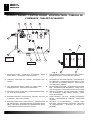
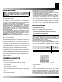
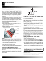
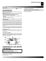
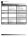
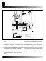
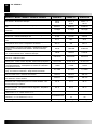
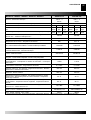
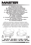
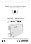
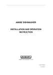
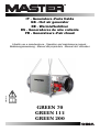
IT - Generatore d’aria Calda
GB - Hot air generator
DE - Warmlufterhitzer
ES - Generadores de aire caliente
FR - Generateurs d’air chaud
4031.812
Libretto uso e manutenzione - Operation and maintenance manual Bedienungsanweisung - Manual del proprietario - Manuel de L’utilisateur
GREEN 70
GREEN 115
GREEN 200
GREEN 70
GREEN 115
GREEN 200
2
QUADRO COMANDI - CONTROL BOARD - KONTROLLTAFEL - TABLEAU DE
COMMANDE - TABLERO DE MANDOS
4
11
9
2
0
1
2
3
6
8
GREEN 70
GREEN 115
8
10 1
F
7
L2
L1
GREEN 200
Fig. 0
5
12
1. Spia tensone quadro - Control lamp - Kontrollampe - testigo 7.
tensión tablero - Lampe temoin mise sous tension
Porta fusibile per bruciatore - Burner fuse holder - Sicherungschalter für brenner - Porta fusible para quemador
2. Interruttore - Control knob only - Schalter - Conmutador - Com- 8.
mutateur
Pressacabvo per termostato ambiente - Cable fastener for
room thermostat - Raumthermostat kabel führung - Prensa cable para de termostato ambiente - Presse etoupe
pour thermostat d’ambiance
3. Cavo alimentazione elettrica - Power cord - Elektro kabel Cable alimentación - Cable electrique alimentation
Spia termostato di sicurezza - Overheat thermostat control
lamp - Überhitzungschutz kontrollampe - Testigo termostato de seguridad - Lampe temoin securite de surchauffe
9.
4. Presa per bruciatore - Burner plug - Sicherungschalter für bren- 10.
ner - Enchufe para quemador
Spia blocco ventilatore - Fan stop control lamp - Ventilator
“aus” kontrollampe - Testigo bloqueo ventilador - Lampe
temoin arret ventilateur
5. Termostato ventilatore - Fan thermostat - Luftregler - Termosta- 11.
to ventilador - Thermostat ventilateur
Riarmo ventilatore - Fan reset - Ventilator entriegelungs
schalter - Restablecimiento ventilador - Rearmement
ventilateur
6. Termostato di sicurezza a riarmo manuale - Limit thermostat 12.
with manual restart - Sichereitsthermostat mit manueller entriegelung - Termostato de seguridad con restablecimiento manual
- Thermostat de securite a rearmement manual
Termostato di sovratemperatura - Overheat safety
thermostat - Überhitzungschutz Thermostat - Termostato
de sobretemperatura - Thermostat de securité de
surchauffe
HOT AIR GENERATOR
DESCRIPTION
Warning: Only the burners which are chosen and supplied by the manufacturer can be used. If another type
of burner is used the heater no longer complies with CE
regulations.
GREEN space heaters have been designed for use in small
to medium-sized rooms and buildings where a fixed or mobile
heating system is required.
Heat is produced by combustion and the heat from the smoke
is transmitted to the fresh air through the metal walls of the
combustion chamber and the heat exchanger. The combustion
chamber is of the type where smoke circulates twice.
The air and smoke pass through separated ducts, both of which
are welded and sealed. When, after combustion, the waste gases have cooled, they are expelled through a duct which must
be connected to a chimney or chimney flue. The chimney or
chimney flue must be big enough to guarantee that the smoke
is expelled efficiently.
The air which is used in combustion is aspirated directly from the
room or building which is being heated. It is therefore of utmost
importance that the room or building be properly ventilated so
that enough fresh air is circulating at all times.
GREEN heaters can operate with burners that are fuelled by
heating oil, methane (G20) or L.P.G. (butane G3O and propane
G31) of the ON-OFF type.
There are three safety devices which are activated in case of
serious malfunction. The Burner Control Device, which is mounted on the burner and has a restart button, automatically stops
the burner if the flame goes out. The Overhrat Thermostat, L2,
of the manuel restart type, is activated if the temperature of the
combustion chamber rises above the set maximum limit; the
warning light (9) lights up and the heater stops working. The
Thermal Relay, RM, is activated if the fan motor starts to use
more electrical current than the maximum permitted limit; the
warning light (10) lights up and the heater stops working.
If any of these safety devices are activated you should check
carefully what the problem actually is before pressing the restart
button and starting the heater off again (“OBSERVED FAULTS,
CAUSES AND REMEDIES”). Overheat safety thermostat, L1,
shuts down the heater if air flow is not sufficient to cool off combustion chamber: the heater will restart automatically as soon as
the heater has cooled down enough (the lamp(9) lights up and
then it cuts down).
7
GB
• After use make sure the disconnecting switch is off.
When using any type of space heater it is obligatory:
• not to exceed the maximum level of heat output of the furnace
(“TECHNICAL SPECIFICATION TABLE”);
• to make sure that there is adequate air circulation and air supplyto the heater and that nothing is obstructing the aspiration
and expulsion of air; movement of air may be obstructed in
various ways including placing covers or other objects on the
heater or positioning the heater too near a wall or other large
object. If the airflow is not adequate, the combustion chamber
will over heat and the overheat safety thermostat L1 will turn
the burner off and on continnously (“OBSERVED FAULTS,
CAUSES AND REMEDIES”).
INSTALLATION
Warning: The following operations must be carried out by
qualified personnel only.
ELECTRICAL CONNECTIONS AND SETTINGS
Warning: The mains supply to the heater must be earthed
and have a magneto-thermal switch with differential.
The power cord must be connected to a switch board
which has a disconnecting switch.
Every space heater is supplied along with the safety and control
devices which are indispensable to the correct functioning of the
unit.The electric switchboard, burner, the fan thermostat, over
heat safety thermostat and the overheat thermostat with manual
restart have already been connected.
The following operations must now be carried out:
• Plug in the power cord having read the adhesive label which details electricity supply characteristics (Table 1). Table 2
shows the adhesive label on units which have three-phase
supply;
Model
M - M/C
Number of phases
Tension
Frequency
Model
T - T/C
1
3
[V]
230
230/400
[Hz]
50
50
Tab. 1
GENERAL ADVICES
The space heater must be installed, set up and used in accordancewith existing laws.
Here are a few general guidelines which should be followed:
• Follow the instructions in this booklet very carefully;
• Don’t install the heater in places where there may be a risk of
fire or explosion;
• Inflammable material should be kept at a safe distance from
the heater (Minimum 3 meters);
• All fire prevention regulations must be adhered to;
• The room or building which is being heated must be sufficiently
ventilated so that the heater has enough air to function properly;
• The heater must be near a chimney or chimney flue and a suitable electric switchboard;
• Don’t let animals or children near the heater;
❏ 230V - 3~ - 50Hz
❏ 400V - 3~ - 50Hz
Tab. 2
• The burner must be connected to the fuel supply (“Burner Instruction Manual”);
• Connect the burner to the electricity supply with the burner
plug;
• Connect accessories such as the room thermostat or clock to
the unit’s electric switchboard: electric wire must be connected
by means of the cable fastener (8) to the terminals (6) and (7).
Having completed all these operations check carefully that all
electrical connections correspond to the wiring diagram. When
the heateris first turned on you must check that the fan does not
use more current than the maximum permitted limit. Finally, to
8
GB
HOT AIR GENERATOR
regulate the burner follow the instructions in the Burner Instruction Manual.
CONNECTION TO HOT AIR DUCTS
The space heater provides heat by releasing and dispersing
hot air. An air head is supplied with each unit and it can be
connected to new air ducts if the user wishes to satisfy specific
needs. In this case and in particular if the diameter and length
of the ducts have been changed or if the number of bends has
been modified, air output may vary. Consequently it is very important to check and regulate air output when any modification
is made to air heads or air ducts. In all circumstances you must
ensure that:
•The fan motor does not absorb more current than the maximum
permitted limit;
• The volume of air flow corresponds to the recommended level.
If the heater is equipped with centrifugal fan and if the volume of
hot air differs from preset values proceed as follows (Fig.1):
1) Remove the aspiration grill which is on fan motor side of the unit;
2) Remove the screws (2) from the motor slide.
3) Remove the belt (1);
4) Loosen the bolts (3);
5) Turn the pulley clockwise and anti-clockwise in order to increase or reduce the volume of air;
6) Tighten the bolts (3);
7) Put back the aspirations grill;
8) Repeat operations (1) -(7) until the correct volume of air
flowhas been achieved.
2
1
3
4
Fig. 1
DRAFT
Efficient combustion and trouble-free working of the burner depend on efficient flue draft. The unit must be connected to the
chimney flue in accordance with current legal regulations and in
line with the following guidelines:
• The tube which carries the smoke should cover as short a distance as possible and should slant upwards;
• There should be no sharp bends in the tubes and the diameter
of the tubes must never be reduced;
• Every heater must have its own chimney;
• Flue draft must at least correspond to the minimum compulsory
level in the Technical Specifications.
ANALYSIS OF COMBUSTION WASTE PRODUCTS
The probes which check the composition of combustion waste
products and smoke temperature must be positioned as indicated in Fig.2.
When these tests have been completed the hole which was
drilled for the probe must be sealed with a material which is
resistant to high temperatures and which ensures that the tube
remains airtight.
200 mm
Fig. 2
CONNECTION TO FUEL SUPPLY AND CHANGING FROM
ONE TYPE OFGAS TO ANOTHER
To connect the burner to the fuel supply follow the instructions in
the Burner Instruction Manual.
The burner can use both methane gas and L.P.G. The gas used
to predispose the heater at factory has been declared on data
plates applied on the box and on the heater it self (methane,
G20, or L.P.G., G30, G31).
To change from methane gas to L.P.G. or vice-versa you must:
• adapt the burner following the instructions manual;
• repeat regulation of combustion while composition of combustion waste products are checked.
• correct data plate on the heater writing which type of gas must
be used.
REGULATION OF COMBUSTION - I°OPERATION
After having checked the hermetic seal of line and of combustion waste products line, heater may be operated for the first
time.
To perform regulation of combustion correctly, combustion waste products must be analyzed using appropriate instruments:
values recommended by actual standards must be reached.
Adjustments to be carried out are described in the Burner Instruction Manual; final values of CO2 shall be correspondant to
excess air factor of 1,2 (12,5% for gas-oil, 9,7% for G20, 9,6%
for G25, 11,7% for G30 and 11,7% for G31) while CO level shall
be less than 75 ppm.
INSTRUCTIONS FOR USE
SWITCHING ON
• Set the control knob (2) in position “0”;
• Turn on the disconnecting switch on the electric switchboard;
• If the unit is operated manually turn the control knob to .The
burner starts up, the combustion chamber heats up and then
the fan starts;
• If the unit operates automatically set the room thermostat at the
desired level and turn the control knob (2) to : the heater will
now start and stop automatically.
• If the heater doesn’t start after you have completed the above
operations consult the Troubleshooting section of this manual.
TURNING OFF
Warning Never stop the heater by simply turning off the
disconnecting switch on the electric switchboard. The
electrical supply must only be disconnected when the fan
has come to a complete stop.
In manual operation turn control knob (2) to “0” or turn off control
in automatic operation.
The burner stops while the fan turns itself on and off until the
combustion chamber has completely cooled down.
WARMLUFTERHITZER
VENTILATION
When the control knob is turned to the symbol
rates in continuous fan mode.
the heater ope-
MAINTENANCE
WarningThe following operations must be carried out by
qualified personnel only.
Before carrying out any maintenance operation the heater
must be disconnected from the mains. Therefore:
• Stop the machine as instructed above
• Turn off the disconnecting switch on the electric switchboard
• Wait until the heater has cooled.
CLEANING THE HEAT EXCHANGER AND THE COMBUSTION CHAMBER
For the heater to operate efficiently the heat exchanger and
combustion chamber must be cleaned after a period of prolonged use and more frequently if too much soot builds up. Soot
builds up when there is not enough chimney draft, when the fuel
is of very poor quality, when the burner is regulated incorrrectly
or when the heater is switched on and off too frequently. If the
heater starts vibrating when it isturned on there is probably too
much soot.
To get at the heat exchanger (1) take off the front panel (3) and
then remove the smoke box panel (2) and remove baffle plates
(7). To get at the combustion chamber (4) remove the burner (5).
CLEANING THE FAN
Remove any dirt or extraneous material from the mesh of the
aspiration grill (6) and if necessary clean the propeller with an
air-suction tool.
CLEANING THE BURNER
For the heater to work efficiently the burner must be serviced
regularly by an Authorized Service Technician. All cleaning, servicing and regulation operations must be carried out as indicated in
the Burner Instruction Manual.
2
7
1
3
5
6
4
Fig. 3
TRANSPORTING AND MOVING
THE HEATER
Warning: Before moving a unit:
• Turn it off as indicated above
• Disconnect electricity by pulling out the plug
• Wait until the heater cools down
The heater has four hooking points at the four top corners. The
heater should be moved or lifted by means of ropes or chains
connected to the hooking points.
The heater can be:
9
DE
• suspended with ropes and/or chains or aupporting beams
• mounted on a supporting base.
In both cases check carefully in the Technical Specifications that
all parts of the heater can take the strain of lifting.
Warning: Never try to lift the heater manually. Doing so could
result in physical injury.
10
GB
HOT AIR GENERATOR
OBSERVED FAULTS, CAUSES AND REMEDIES
Problem
Cause
Remedy
The heater won’t start
1.Faulty electrical supply
1. Check function and positioning of main switch
1. Check power cord
1. Check electrical connections
1. Check fuses
2. Put main switch in correct position
3. Check setting of room thermostat
3. Check function of room thermo-stat
4. Press the appropriate restart button
2.Wrong positioning of main switch
3.Wrong setting of room thermostat
4.Safety device (burner, thermostat L) not
restarted after repairs
Thermostat L cuts in (the lamp (9)
light up and then it cuts down)
1.The combustion chamber has overheated
1. Check fuel flow
1. Check position registers, draw-holes, etc.
1. Remove extraneous material from air ducts and
ventilation grills
Thermostat L2 cuts in (Warning
lamp (9) lights up)
1. Excessive combustion chamber over 1. Check as indicated above
heating
1. If fault persists contact our Service Center
Thermal relay RM cuts in (warning 1. Fan current absorption is excessive
light (9) lights up)
1. Heater with helicoidal ventilator: remove eventualdebris preventing free flow of air on intake
and outlet. Check length of air ducts, reduce if
excessive.
1. Heater with centrifugal ventilator: check setting of
transmission belt as indicated in chapter (“CONNECTION TO HOT AIR DUCTS”).
1. Always check that current absorption remains below value indicated on motor manufacturer plate
The burner starts up, the flame
doesn’t light up and the restart
light comes on
1.Burner not working correctly
1.Press the restart button to turn on the heater. If
the same problem arises again call an Authorized
Service Technician
The fan doesn’t start up or starts
up late.
1.No electrical power
3.Winding of motor burnt or interrupted
4.Condenser burnt
5.Motor bearings blocked
1. Check fuses
1. Check electrical connections
2. Check the thermostat, set it and replace it if
necessary
3. Replace the fan motor
4. Replace the condenser
5. Replace the bearings
The fan vibrates or makes
unusual noise
1. Extraneous material on fan blades
2. Not enough air circulation
1. Remove extraneous material
2. Remove obstacles to air circulation
Not enough heat
1.Wrong burner
1. Call an Authorized Service Technician
2.F thermostat out of order
24
IMPIANTO ELETTRICO - ELECTRICAL DIAGRAM - ELEKTRO SKEME
DIAGRAMA ELÉCTRICO - DIAGRAMME ÉLECTRIQUE
230 V - 1~ - 50Hz
RF
FILTRO GASOLIO RISCALDATO
FILTRE GASOIL RECHAUFFE
HEIβFILTER
HEATED FILTER
FILTRO GASOIL CALENTADO
M
MOTORE VENTILATORE - FAN MOTOR - VENTILATOR RM
MOTOR - MOTOR VENTILADOR - MOTEUR VENTILATEUR
RELÈ TERMICO VENTILATORE - FANS THERMAL RELAY
- THERMOLAIS FÜR VENTILADOR - RELÈ TÉRMICO
VENTILADOR - RELAIS THERMIQUE DES VENTILATEUR
F
TERMOSTATO VENTILATORE - FAN THERMOSTAT ST
- LUFTREGLER - TERMOSTATO VENTILADOR - THERMOSTAT VENTILATEUR
SPIA TENSIONE QUADRO - CONTROL LAMP - KONTROLLAMPE - TESTIGO BLOQUEO VENTILADOR - LAMPE TEMOIN MISE SOUS TENSION
FB
FUSIBILE BRUCIATORE - BURNER FUSE - SICHERUNG SB
FÜR BENNER - FUSIBLE QUEMADOR - FUSIBLE BRULEUR
SPIA BLOCCO VENTILATORE - FAN STOP CONTROLL
LAMP - VENTILADOR “AUS” KONTROLLAMPE - TESTIGO
BLOQUEO VENTILADOR - LAMPE TEMOIN ARRET VENTILATEUR
TM
TELERUTTORE VENTILATORE - FANS TELE-CON- BR
TACTOR - FERNSCHALTER FÜR VENTILADOR - TELERUPTOR VENTILADOR - TELERUPTEUR VENTILATEUR
BRUCIATORE - BURNER - BRENNER - QUEMADOR BRULEUR
25
IMPIANTO ELETTRICO - ELECTRICAL DIAGRAM - ELEKTRO SKEME
DIAGRAMA ELÉCTRICO - DIAGRAMME ÉLECTRIQUE
230 V - 3~ - 50Hz
400 V - 3~ - 50Hz
RF
FILTRO GASOLIO RISCALDATO
FILTRE GASOIL RECHAUFFE
HEIβFILTER
HEATED FILTER
FILTRO GASOIL CALENTADO
TA
TERMOSTATO AMBIENTE - ROOM THERMOSTAT RV
- RAUMTHERMOSTAT - TERMOSTATO AMBIENTE THERMOSTAT D’AMBIANCE
INTERRUTTORE ON / OFF / VENTILAZIONE - CONTROL
KNOB HEAT / STOP / VENTILATION ONLY - SCHALTER
HEIZUNG / STOP / LÜFTUNG - COMMUTADOR CALEFACCIÓN / PARO / VENTILACIÓN - COMMUTATEUR CHAUFFAGE / STOP / VENTILATION
C
CONDENSATORE - CONDENSER - KONDENSATOR SL
- CONDENSADOR - CONDENSATEUR
SPIA TERMOSTATI DI SICUR. - OVERHEAT THERMOSTATS CONTROL LAMP - ÜBERHITZUNGSCHUTZEN KONTROLLAMPE - TESTIGO TERMOSTATOS DE SEGURIDAD
- LAMPE TEMOIN SECURITE DE SURCHAUFFE
L1
TERMOSTATO DI SOVRARISCALDAMENTO - OVERHEAT SAFETY THERMOSTAT - ÜBERHITZUNGSCHUTZ THERMOSTAT - TERMOSTATO DE SOBRETEMPERATURA - THERMOSTAT DE SECURITE DE
SURCHAUFFE
L2
TERMOSTATO DI SICUREZZA A RIARMO MANUALE
- LIMIT THERMOSTAT WITH MANUAL RESTART - SICHEREITSTHERMOSTAT MIT MANUELLER ENTRIE
GELUNG- TERMOSTATO DE SEGURIDAD CON RESTABLECIMIENTO MANUAL - THERMOSTAT DE SECURITE
A RIARMEMENT MANUEL
26
OIL VERSION
MODELLO - MODEL - MODELL - MODELO - MODELE
GREEN 70
GREEN 115
GREEN 200
230 V
50 Hz
230 V
400 V - 3
50 Hz
230 V
400 V - 3
50 Hz
Portata d’aria - Air output - Nenn-Lufleistung - Capacidad aire - Débit
d’air
5.000 m³
8.000 m³
12.500 m³
Consumo - Comsumption - Brennstoffverbrauch - Consumo - Consommation
6,8 kg/h
11,3 kg/h
18,6 kg/h
Alimentazione elettrica - Power supply - Stromanschluß - Alimentación eléctrica - Alimentation électrique
Combustibile - Fuel - Brennstoff - Combustible - Combustible
Potenza termica max - Max. power - Max. Wärmeleistung - Potencia
térmica máx. - Puissance thermique max.
Gasolio - Oil - Heizöl - Gasoil - Fuel
81 kW
134 kW
220 kW
Rendimento - Efficiency - Wärmeleistung - Rendimiento - Rendement
87 %
89%
90 %
Temperatura dei fumi - Temperature of smokes - Rauchtemperatur
- Temperature de los humos - Température des fumées
282 °C
220
200 °C
Potenza elettrica - Fan power consumption - Ventilatormotor Leistunsaufnahme - Potencia eléctrica del ventilador - Puissance électrique
ventilateur
523 W
1.500 kW
2.820 kW
Potenza elettrica totale* - Total power consumption* - Leistunsaufnahme* - Potencia eléctrica total* - Puissance électrique*
728 W
1.690 W
2.850 W
Portata dei fumi* - Smokes flow* - Rauchdurchsatz* - Capacidad de
los humos* - Débit des fumées
165 Nm³/h
223 Nm³/h
400 Nm³/h
Pressione statica disponibile - Available static pressure - Verfugbare Stat.
Pressung Max. - Presión estática disponible - Pression statique disponible
10 mm H2O
10 mm H2O
10 mm H2O
Contropressione in camera di combustione* - Burned gases pressure*
- Rauchgaswiderstand* - Contrapresión en cámara de combustión* Contre pression fumées*
1 mbar
1 mbar
1 mbar
Tiraggio minimo al camino* - Compulsory flue draft* - Erforderlicher Kaminzung* - Tiro mínimo a la chimenea* - Tirage minimum nécessaire*
0,1 mbar
0,1 mbar
0,1 mbar
Diametro uscita fumi - Flue diameter - Abgasrohr Durchmesser Diámetro salida humos - Diamètre sortie fumèes
150 mm
200 mm
200 mm
Sezione uscita aria - Air outlet section - Luftauslass querschnitt - Sección salida aire - Section sortie air
450 mm
60 mm
700 mm
Temperatura avviamento ventilatore - Fan starting temperature - Ventilatorthermostat - Temperatura puesta en marcha ventilador - Température démarrage ventilateur
35 °C
35 °C
35 °C
Temperatura limite di sicurezza - Safety limit temperature setting Temperaturwächter - Temperatura límite de seguridad - Température
limite de sécurité
85 °C
85 °C
85 °C
Livello sonoro a 1 m* - Noise level at 1 m* - Geraüschspegel a 1 m*
- Nivel sonoro a 1 m* - Niveau sonore à 1 m*
72,5 dBA
79,6 dBA
81,3 dBA
Dimensioni, L x P x A - Dimensions, L x W x H - Masse, H x B x T - Dimensiones, L x P x A - Dimensions, L x P x H
137,5x92x672 cm 169,5x109x77,2
cm
218x140x80,4
cm
Peso - Weight - Gewicht - Peso - Poids
128 kg
195 kg
360 kg
*= Con bruciatore Ecoflam - Avec bruleur Ecoflam - Mit Ecoflam Brenner - With Ecoflam burner - Con quemador Ecoflam
GAS VERSION
MODELLO - MODEL - MODELL - MODELO - MODELE
27
GREEN 115
GREEN 200
Alimentazione elettrica - Power supply - Stromanschluß - Alimentación
eléctrica - Alimentation électrique
230 V
400 V - 3
50 Hz
230 V
400 V - 3
50 Hz
Portata d’aria - Air output - Nenn-Lufleistung - Capacidad aire - Débit d’air
6.000 m³
12.500 m³
Combustibile - Fuel - Brennstoff - Combustible - Combustible
G20
G30
G31
G20
G30
G31
Consumo - Comsumption - Brennstoffverbrauch - Consumo - Consommation
10,5
Nm³/h
8,25
kg/h
8,13
kg/h
22,2
Nm³/h
17,42
kg/h
17,16
kg/h
Pressione gas - Gas pressure - Betriebs druck - Presión gas - pression gaz
20
mbar
29
mbar
37
mbar
20
mbar
29
mbar
37
mbar
Potenza termica max* - Max. power* - Max. Wärmeleistung* - Potencia
térmica máx.* - Puissance thermique max.*
134 kW
220 kW
Rendimento - Efficiency - Wärmeleistung - Rendimiento - Rendement
88,5 %
89,7 %
260
237 °C
Potenza elettrica - Fan power consumption - Ventilatormotor Leistunsaufnahme - Potencia eléctrica del ventilador - Puissance électrique ventilateur
1.060 kW
2.820 kW
Potenza elettrica totale* - Total power consumption* - Leistunsaufnahme*
- Potencia eléctrica total* - Puissance électrique*
1.240 W
2.850 W
Portata dei fumi* - Smokes flow* - Rauchdurchsatz* - Capacidad de los
humos* - Débit des fumées
213 Nm³/h
446 Nm³/h
Pressione statica disponibile - Available static pressure - Verfugbare Stat. Pressung Max. - Presión estática disponible - Pression statique disponible
10 mm H2O
10 mm H2O
Contropressione in camera di combustione* - Burned gases pressure* - Rauchgaswiderstand* - Contrapresión en cámara de combustión* - Contre pression fumées*
1 mbar
1 mbar
Tiraggio minimo al camino* - Compulsory flue draft* - Erforderlicher Kaminzung*
- Tiro mínimo a la chimenea* - Tirage minimum nécessaire*
0,1 mbar
0,1 mbar
Diametro uscita fumi - Flue diameter - Abgasrohr Durchmesser - Diámetro
salida humos - Diamètre sortie fumèes
150 mm
200 mm
Sezione uscita aria - Air outlet section - Luftauslass querschnitt - Sección
salida aire - Section sortie air
500 mm
700 mm
Temperatura avviamento ventilatore - Fan starting temperature - Ventilatorthermostat - Temperatura puesta en marcha ventilador - Température
démarrage ventilateur
35 °C
35 °C
Temperatura limite di sicurezza - Safety limit temperature setting - Temperaturwächter - Temperatura límite de seguridad - Température limite de
sécurité
85 °C
85 °C
Livello sonoro a 1 m* - Noise level at 1 m* - Geraüschspegel a 1 m* - Nivel
sonoro a 1 m* - Niveau sonore à 1 m*
78,1 dBA
81,3 dBA
Dimensioni, L x P x A* - Dimensions, L x W x H* - Masse, H x B x T* - Dimensiones, L x P x A* - Dimensions, L x P x H*
152x96x70,2 cm
218x140x80,4 cm
Temperatura dei fumi - Temperature of smokes - Rauchtemperatur Temperature de los humos - Température des fumées
Peso - Weight - Gewicht - Peso - Poids
160 kg
360 kg
*= Con bruciatore Ecoflam - Avec bruleur Ecoflam - Mit Ecoflam Brenner - With Ecoflam burner - Con quemador Ecoflam