1
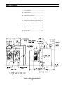
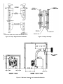
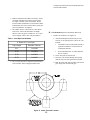
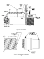
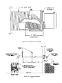
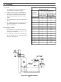
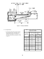
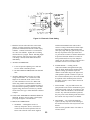
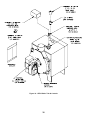
e. Secure the inside trim plate to inside wall.
a. All horizontal runs must rise at least ¼ inch per
foot toward vent terminal.
f. Tighten the gear clamp to the terminal pipe.
b. Avoid any sags or dips in vent pipe.
g. Seal all external joints with a weatherproof caulk.
C. Air Intake Installation (Direct Vent only)
2. Cut vent pipe to length with a hack saw.
See Figure 13.
3. Install Vent Connector/Appliance Adaptor. See
Figures 11 and 12.
a. Apply a continuous bead of high temperature
adhesive/sealant (supplied with boiler) around
outside of corrugated pipe of vent connector.
b. Twist vent connector into end of vent pipe.
Turn the connector counter-clockwise until it is
engaged approximately 4 inches into the inner
vent pipe and the outer collar of the connector
overlaps the outside of the vent pipe.
1. General
a. Use 4 inch diameter single wall metal pipe and
fittings available at most heating distributors.
Maximum allowable air intake length is 40
equivalent feet. Each elbow is equal to 6
equivalent feet.
c. Tighten the gear clamp on the outer collar of the
connector.
d. Repeat steps a. through c. with the appliance
adapter.
4. Connect vent pipe to boiler.
b. Start at Burner. Work toward air intake terminal.
a. Apply a continuous bead of high temperature
adhesive/sealant (supplied with boiler) to inside
of appliance adapter (approximately ½ inch
from end).
c. Maintain minimum of ¼ inch per foot slope in
horizontal run to air intake terminal. Slope
down toward air intake terminal.
d. Seal all joints gas-tight, using silicone caulk or
self-adhesive aluminum tape.
b. Slip appliance adapter over boiler flue collar and
tighten gear clamp.
2. After determining location, cut a hole in the wall to
accept 4 inch air intake pipe.
5. Connect vent pipe to terminal.
a. Carefully slide insulation sleeve over vent
connector and vent pipe until gear clamp on
small end of connector can be accessed.
3. Remove the black plastic inlet cover from the right
side of the Beckett AFII burner.
4. Mount the vacuum relief valve tee assembly or 90°
elbow into the burner inlet ring. See Figure 13.
a. Secure with at least three (3) sheet metal screws
evenly spaced around the burner inlet ring.
b. Assemble the vacuum relief valve balance
weight onto the gate. Refer to the vacuum relief
valve manufacturer's instructions.
b. Apply a continuous bead of high temperature
adhesive/sealant (supplied with boiler) on inside
of cent connector (approximately ½ inch from
end).
c. Mount the vacuum relief valve into the tee and
fasten with a screw and nut in collar tabs. To
ensure proper operation, the gate must be level
across the pivot point and plumb. Refer to
vacuum relief valve manufacturer's instructions.
c. Clip connector over vent terminal until it is fully
engaged. Then tighten gear clamp.
d. Slide insulation sleeve over terminal connection
so that connector is completely covered.
5. Install remainder of air intake, securing each joint
with at least three (3) sheet metal screws evenly
spaced.
e. Secure each end of insulation sleeve with the
gear clamps provided.
6. Secure vent pipe in position with pipe straps.
16