1
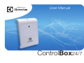
User Manual
ControlBox24/7
TABLE OF CONTENTS
Introduction
Safety regulations
Description
Electricity supply
Getting started
Programming
Formatting programming strings
Enter reporting number
Low temperature warning
Entering heat pump model
Programmable mode
Initiation of remote control IR signal
Programming your own IR signals
Remote control your heat pump
Other settings
Temperature compensation
Redirecting the confirmation message
Check current settings
Enter country code
Command - list
Installation
Troubleshooting
Key to reports
Reset default settings
Errors - remedy and cause
Specification
3
3
4
6
7
8
8
8
9
10
11
11
12
13
14
14
15
15
16
17
18
19
19
19
20
21
2
INTRODUCTION
Checking a heat pump via texting
A ControlBox24/7 can be used for remote control of a heat pump using text messages. You can combine and choose between heating, cooling and
other temperature settings and fan speeds. ControlBox24/7 also provides the possibility of programming your own IR signals for other heat pump
brands. Simple, selectable commands allow you to quickly change mode and temperature, even for non-Electrolux heat pumps.
AirCare - Generate complete text messages via an app
If you have a smartphone, you can also use an app which generates a text message for you, and sends it to your ControlBox24/7. The apps can be
downloaded from App Store for iPhone and Google Play for Android under the name ‘AirCare’.
Monitoring
ControlBox24/7 also facilitates monitoring temperature and power outages. A text message will be sent to recipients of your choice if the
temperature drops below a set value, or in the event of a power outage.
SAFETY REGULATIONS
•
•
Do not let persons, children included, with reduced physical sensory, reduced mental functions or lack of experience and knowledge use the
appliance. They must have supervision or instruction for the operation of the appliance by a person who is responsible for their safety.
Do not let children play with the appliance.
3
DESCRIPTION
4
DESCRIPTION
9 GSM test button
Press the button to read current GSM signal strength. The GSM
indicator will flash from 1 to 10 times, depending on strength (1 =
low signal strength, 10 = high signal strength)
1 IR transmitter
2 IR transmitter
Sends IR signals to your heat pump, and has a range of up to 10
metres.
10 IR test button
Sends a test signal to your heat pump.
- HL mode: Sends the following setting: “Heat 16°C” with
automatic fan speed”.
- HX mode: Sends the following setting: “Heat 18°C” with
automatic fan speed”.
- PM mode:
Sends the programmed signal in the first slot.
If nothing has been programmed, no signal
will be sent.
3 Current indicator (green)
ON:
External power supply connected.
OFF:
External power supply disconnected.
4 Battery indicator (green)
ON:
Normal battery status.
OFF:
Battery disconnected or battery on/off switch is
switched off.
Flashing: Low battery level.
11 External power supply
Connection for 12V DC, 1A current adapter.
5 GSM indicator (red)
ON:
No GSM signal. Seeking GSM signal.
OFF:
GSM module has signal and working normally.
Flashing: Error on GSM module, no SIM card.
12 Battery on/off switch
ON:
The integrated battery will power the unit in the event
of power loss from the external power connection.
OFF:
The unit will not work without an external power
supply being connected
6 IR indicator (orange)
OFF:
Normal setting
Rapid flashing:
Sends IR signal via IR transmitter.
Slow flashing:
Awaiting incoming IR programming signal to I
R receiver.
Lit for 3 seconds: IR signal programming successful.
13 SIM card holder
Cover for the SIM card holder and battery switch.
NOTE! When installing the SIM card, the battery switch must be in
the off position, and the external power supply disconnected.
7 IR receiver
Discreetly placed IR receiver. Reads IR signals through unit housing,
and does NOT need to be exposed by making a hole.
8 Temperature sensor
Reads current room temperature. Do not block this hole.
5
ELECTRICITY SUPPLY
•
The unit is powered by the voltage adapter supplied (230V AC / 12V DC 1A)
•
Rechargeable backup battery:
If the unit is deactivated by a power outage, the integrated battery will power it for up to 12 hours. The battery will be recharged as long as the
external power supply is connected. A full battery charge takes approx. 48 hours.
•
If the external power supply is disconnected for more than 15 seconds, the power indicator light will go out, and 15 minutes later, a text
message stating “AC Power - FAIL, (15 minutes ago)” will be sent.
•
When the external power supply is reconnected, the power indicator light will come on, and 15 minutes later, a text message stating “AC Power
- RESTORED, (15 minutes ago)” will be sent.
•
If the battery is low, the battery indicator light will start to flash when 20% of battery capacity remains. 3 minutes after the light starts to flash, the
following text message will be sent: “Battery - LOW”.
•
When the external power supply has been restored for more than 15 seconds, the battery indicator light will come on again. The battery will be
fully charged again after charging for approx. 48 hours.
6
GETTING STARTED
Choice of mobile operator
When choosing a mobile operator for the SIM card in your ControlBox24/7, always consider the following:
• ControlBox24/7 works best with GSM/2G, which means that operators which only provide 3G WILL NOT work with the unit.
• Choose the operator with the best GSM cover in the area where you intend to locate your ControlBox24/7.
• If using a prepaid card, remember that most SIM cards will deactivate unless they are regularly topped up. Check with your mobile operator.
Fitting the SIM card
1. Open the SIM card cover on the back of the unit. Set the battery
switch to “OFF” and disconnect the external power supply.
2. Open the slide in which the SIM card will be inserted by carefully
pressing it from the battery switch, raising the slide and inserting
the SIM card with the bevelled corner closest to the battery switch
when the slide is pressed down.
3. Lower the slide and press it carefully sideways towards the battery
switch until you hear a slight “click”.
4. Connect the external power supply and then switch the battery
switch to the “ON” position. Screw the SIM card cover back into
place.
Important!:
For the ControlBox24/7 to work, the PIN code request must be
deactivated on the SIM card before inserting it in the unit!
7
PROGRAMMING
Formatting programming strings
All commands to the unit must be given in capital letters. It is therefore important that you use CAPITALS when sending commands to the unit.
Formulate commands to the unit as follows:
<COMMAND> + <space> + <VALUE>
Examples of all commands are given later in this manual.
The unit will always acknowledge a successful command with “Confirmed: <STATED COMMAND STRING>” so that you know that the
command has been correctly given and executed.
If an incorrect command is sent to the unit, it will automatically forward the message to the primary reporting number (TEL1) with the following prefix:
“Unknown command”.
Enter reporting number
To enable the unit to know which status reports to send, one or more numbers must be entered. Up to 5 different numbers can be entered for
receiving status reports.
To save a number as the unit’s primary reporting number (TEL1) send the following text message to ControlBox24/7;
TEL1 <NUMBER>
Example: TEL1 070765874
To enter more report recipients, replace TEL1 with TEL2, TEL3, TEL4 or TEL5.
To delete a registered report number, replace the telephone number with DEL as follows:
TELx DEL
Example: TEL2 DEL
The primary reporting number TEL1 differs from the others as follows: if an unknown or incorrect
command is sent to the unit, it will be automatically forwarded to the number saved as TEL1.
8
TIP!
If you send TEL? to ControlBox24/7,
you will receive a list of all telephone
numbers stored in return.
PROGRAMMING
Temperature warning
The unit will automatically report if the temperature will exceed the set value. The default setting for low temperature alarm is +5°C and for high
temperature 30°. These values can be changed to between 0°C and +50°C. To change a set value, send the following text message to the unit:
LOW TEMPERATURE ALARM
HIGH TEMPERATURE ALARM
LTWARN <NUMBER>
HTWARN <NUMBER>
Example: LTWARN 12
Example: HTWARN 27
The example above will cause the unit to send a warning report when the The example above will cause the unit to send a warning report when the
temperature falls below 12°C, as
temperature exceeds 27°C as
“Temperature - LOW”.
“Temperature - HIGH”.
If the temperature then increases again and reaches the set value,
another message will be sent saying:
“Temperature - RESTORED”
If the temperature then decreases again and reaches the set value,
another message will be sent saying:
“Temperature - RESTORED”
The unit’s temperature warning function can be easily activated or
deactivated using the following command:
The unit’s temperate warning function can be easily activated or
deactivated using the following command:
Activation:
LTWON
Deactivation: LTWOFF
Activation:
HTWON
Deactivation: HTWOFF
(default setting)
(default setting)
Request current temperature
To see what the current temperature is where your ControlBox24/7 is located, send the following text message to the unit:
TEMP
9
PROGRAMMING
Entering heat pump model
ControlBox24/7 is designed to suit several models of heat pumps, and therefore has to know which model you have. To make this setting, you need
to know which model of heat pump you have. If your heat pump is not an Electrolux model, you can select the programmable mode, and enter up
to 10 different IR signals.
The following 3 modes can be set:
EHEAT - Electrolux Model: Eco Heat. (default setting)
ECOOL - Electrolux Model: Eco Cool.
CHEAT - Electrolux Model: Comfort Heat.
CCOOL - Electrolux Model: Comfort Cool.
HXHEAT - Electrolux older heat pump ranges.
PM - Programmable setting, 10 fixed commands can be entered.
To enter the heat pump to be used, send the following text message to the unit.
TYPE <MODE>
Example: TYPE HXHEAT
Once you have made this setting, the unit is ready to be used. See “Remote control your heat pump”.
NOTE! If you have selected the “PM” mode, the IR command has to be programmed in before the unit can control your heat pump. See
“Programmable mode”
10
PROGRAMMING
Programmable mode
If you have a non-Electrolux heat pump or other appliance with an IR receiver you want to control, you can use programmable mode. Up to 10
different fixed IR signals can be programmed in using individual commands.
NOTE!
To program your own IR signals, the unit must be in programmable mode, see chapter “Programming - entering heat pump model” for
further instructions.
Follow the steps below to program new or replace old IR signals.
Initiation of remote control IR signal
1. Start by switching off your heat pump, so that the remote control shows that the pump is
switched off.
2. The ControlBox24/7 must first read what type of IR signals your unit uses. Send the following text
message to ControlBox24/7: RS
3. The unit will go into learning mode, as shown by the IR indicator light flashing slowly for 1 minute,
during which you must perform the next step.
NOTE!
When the command RS is sent
to ControlBox24/7, all previously
programmed signals will be deleted.
4. Aim your remote control at the IR receiver on the right side of the ControlBox24/7 and press the
ON/OFF button on your remote control to start the heat pump.
5. The IR indicator will now indicate that an IR signal is being received by remaining lit for 3 seconds, and will then begin to flash slowly again. Aim
your remote control at the IR receiver on the right side of the ControlBox24/7 again, and press the ON/OFF button once more.
6. Once the initiation process is completed and successful, the ControlBox24/7 will confirm by sending the following text: “Learning SUCCESSFUL”. NOTE! The initiation process will not save any IR signal unless it has read which IR format is to be used.
11
PROGRAMMING
Programming your own IR signals
ControlBox24/7 can store 10 programmed IR signals. You can give each program a name. Follow the instructions below to program an IR signal in
1 minute.
1. Prepare your remote control so that all the settings you want show on the display, and then switch the remote control off.
2. Send the following text message to the unit:
Rx <COMMAND NAME>
Example: R1 Summer
X = program 1-10
You can use upper and lower case letters and numerals in your command name. (Space or special characters cannot be used)
3. The IR indicator light will start to flash slowly for 1 minute, during which you must aim the control at the IR receiver on the right side of the
ControlBox24/7, and press the ON/OFF button on your remote control.
4. The IR indicator will remain lit for 3 seconds, and the ControlBox24/7 will send one of the following programming confirmations (see below for
explanation):
“Learning - SUCCESSFUL”
“Learning - FAILED”
“Learning - TIMED OUT”
- Programming concluded successfully.
- Programming failed. Repeat the process from step 1.
- No IR signal received, or programming took too long. Start again from step 1.
To use the example above, send a text message saying Summer to ControlBox24/7.
NOTE! For programmed IR signals to work, ControlBox24/7 MUST be in “PM” mode. See “Programming - entering heat pump model”
12
REMOTE CONTROL YOUR HEAT PUMP
Flexible control (Only works with Electrolux heat pumps)
Once ControlBox24/7 has been set up for the correct heat pump model, you can control your heat pump by sending text message to the unit.
Follow the instructions below for giving the command. Please note that this command will start the heat pump even when it is switched off.
The modes which can be selected on the heat pump are: HEAT, COOL and DRY.
To send a setting to the pump WITHOUT specifying a fan speed, enter the following:
<MODE><space><TEMPERATURE>
Example: HEAT 20
In the example above, the following setting is sent to the heat pump “Heat, 20°C, automatic fan speed”
An alternative to send to the heat pump is to state a specific fan speed by adding a colon after the temperature, and then entering the desired fan
speed. See the following:
<MODE><space><TEMPERATURE>:<FAN SPEED>
Example: COOL 18:2
TIP!
By sending the OFF command, you
can also switch off the heat pump.
In the example above, the following setting is sent to the heat pump “Cool, 20°C, fan speed 2”.
A list of the available settings for the various models is shown below.
*DRY = nonadjustable fan speed.
COOL
DRY
HEAT
Fan speed
EHEAT
16-30
16-30 *
8, 16-30
0 (auto), 1-5
ECOOL
16-30
16-30 *
8, 16-30
0 (auto), 1-5
CHEAT
CCOOL
16-30 *
8, 16-30
0 (auto), 1-3
16-30 *
8, 16-30
0 (auto), 1-3
13
HXHEAT
18-32
0 (auto), 1-3
OTHER SETTINGS
Temperature compensation
If your ControlBox24/7 is located where the temperature is consistently a few degrees higher or lower than where you want to measure it, you can
adjust the temperature on the unit.
To compensate the monitored temperature, send the following text message to your ControlBox24/7:
TADJ <X><YY>
X
YY
=
=
0 for positive value, 1 for negative value.
05
10
15
20
25
30
35
0.5°C 1.0°C 1.5°C 2.0°C 2.5°C 3.0°C 3.5°C
If you want your ControlBox24/7 to show 2.5 degrees higher than the actual temperature measured, send the following text message to the unit.
TADJ 025
Where “0” stands for “+”, i.e. the temperature reported will show 2.5°C above the actual temperature where ControlBox24/7 is
located.
If you want to adjust the temperature shown downwards 1.5°, send
TADJ 125 Where “1” stands for “-”, i.e. the temperature reported will show 1.5°C below the actual temperature where ControlBox24/7 is located.
To deactivate temperature compensation, send:
TADJ 000
14
OTHER SETTINGS
Redirecting the confirmation message
By default, your ControlBox24/7 will send all correctly formulated commands back to the same telephone number they came from.
If your ControlBox24/7 is used by other people, and you want to direct all confirmations of incoming commands to the unit to a single number, you
can designate a standard telephone number as follows:
STEL <X>
X=
Example: STEL 1
0
1
Inactive TEL1
2
TEL2
3
TEL3
4
TEL4
5
TEL5
In the example above, all confirmations will be sent to the telephone number saved at TEL1 - See “Programming - Set up reporting number”.
Redirecting the confirmation message
To check which settings your ControlBox24/7 has at any time, you can request them by entering the following:
SET?
ControlBox24/7 will return all settings made on the unit.
15
OTHER SETTINGS
Enter country code
Certain mobile operators remove the country code from incoming texts, which can cause a problem if ControlBox24/7 has to be controlled from
a country other than where it is placed. A problem can arise sending back the confirmation message (only applies if the STEL commando is
deactivated). If the problem does occur, you can use the following command to work around it:
NACO 0&<XXXX>
Example: NACO 0&0046
0
= The numbers to be replaced by the country code (usually a zero)
XXXX = Country code where the mobile sending the command is located.
The example above enters the country code when the command text message was sent from Sweden and the ControlBox24/7 is in another
country. i.e.: it is the mobile which sends the text message which determines which country code will be stated.
To remove the country code setting stated, send the following text message to ControlBox24/7;
NACO &
NOTE! Only state the country code if you find problems with receiving the confirmation message from ControlBox24/7.
16
OTHER SETTINGS
Command - list
Command
HEAT, COOL, DRY
Explanation
Control heat pump setting
Section reference
Flexible control
HTWARN
Sets threshold value for high temperature alarm
Temperature warning
HTWON / HTWOFF
Activates/deactivates warning for high temperature
Temperature warning
LTWARN
Sets threshold value for temperature monitoring
Temperature warning
LTWON / LTWOFF
Activates/deactivates warning for low temperature
Temperature warning
NACO
Setting for country code
Enter country code
OFF
Switches off heat pump
Flexible control
SET?
Returns current settings to ControlBox24/7
Other settings
STEL
Sets standard receiver for confirmations
Confirmation message
TADJ
Adjusts temperature read
Temperature compensation
TEL?
Returns saved reporting phone number
Enter reporting number
TELx
Enter phone number for report reception
Enter reporting number
TEMP
Returns current temperature
Request current temperature
TYPE
Enter which heat pump model is to be controlled
Enter heat pump model
RS
Starts initiation phase for learning non-standard IT signals
Initiation of remote control IR signal
Rx
Starts learning process for non-standard IR signals
Learn IR signals
17
INSTALLATION
Location
IR SIGNAL
ControlBox24/7 has two integrated IR diodes, which send signals via IR light. You must therefore locate the unit with uninterrupted line of sight to
the heat pump to be controlled. Test that the IR signal is received by pressing the IR test button while holding the ControlBox24/7 where it is
to be located, to ensure that the IR signal is received.
GSM COVER
ControlBox24/7 has a built-in GSM module which makes it possible to communicate with the unit via text messages. When deciding where to
locate the unit, it is also important that there is sufficient GSM cover. Hold the unit where you intend to place it and press the GSM test button.
The GSM indicator light will flash 1 - 10 times. The higher the number of flashes, the better the GSM cover.
NOTE! GSM cover must be at least 4 flashes for ControlBox24/7 to work satisfactorily.
Installation
Once you have found the ideal location according to the IR signal’s range and GSM signal strength, screw the mounting plate supplied to the wall
using the screws supplied (using plugs if necessary) and hook the ControlBox24/7 into place. Test the IR and GSM strengths once more using the
test buttons, to ensure that everything is working as it should.
18
TROUBLESHOOTING
Key to reports
Error
External power supply error or disconnected
Text report received
AC Power - FAIL (15 minutes ago)
Delay before report sent
15 minutes
External power supply restored
AC Power - RESTORED (15 minutes ago)
15 minutes
Battery switched off or disconnected
Battery - DISCONNECTED
3 minutes
Battery reconnected
Battery - CONNECTED
3 minutes
Low battery level
Battery - LOW
3 minutes
Low battery level restored
Battery - Restored
12 minutes
High temperature level
Temperature - HIGH (over xC)
3 minutes
Low temperature level
Temperature - LOW (below xC)
3 minutes
Low temperature level restored
Temperature - RESTORED (above xC)
3 minutes
Reset default settings
If you want to delete all settings on your ControlBox24/7, the process is simple, using ‘default reset’. Follow the steps below.
1. Disconnect external power supply and switch off the battery switch under the SIM card cover.
2. Hold down both buttons on the right side of the unit (GSM Test & IR Test buttons) at the same time as you reconnect the external power supply.
3. When all the lights on the front of the unit flash rapidly, release the buttons on the side.
4. Your ControlBox24/7 is now restored to default settings.
19
TROUBLESHOOTING
Causes and solutions
ERROR
Unit will not respond to a text message and will not
execute commands despite all indication lights lighting as
they should. (2 green lights)
Text command executed by ControlBox24/7 but I receive
no text message confirmation
REMEDY/CAUSE
• Check that the SIM card is active and works using a standard mobile phone.
GSM indicator light on constantly.
•
•
•
•
•
GSM indicator flashing slowly.
•
•
Battery indicator light gone out
•
Battery indicator light flashing slowly
•
Power indicator light is off
•
Check that the SIM card can send a text message from a standard mobile phone.
Check that the GSM signal strength is sufficient (Above 4)
Check that STEL command is set correctly.
Check country code setting. (NACO)
The indicator will normally be on for up to 30 seconds during start-up of
ControlBox24/7.
No/poor GSM signal.
Error on SIM card or GSM unit. Test SIM card in standard mobile phone.
The backup battery is either switched off or disconnected, check that the battery
switch is in the ON position.
The unit has lost external power and the rechargeable backup battery is running
out. Check that the external power supply is working and is connected.
The unit has lost external power. Check that the adapter is working and is
connected.
20
SPECIFICATIONS
Product specification
Product name
Electricity supply
ControlBox24/7
12V DC, 1A (via adapter 230V AC 350mA)
No. of IR transmitters
2
IR transmitter range
Up to 10m
No. of IR receivers
1
IR receiver range
Up to 30cm
No. of temperature sensors
1
Temperature sensor - range
+0°C - +50°C
Backup battery
4.8V, Ni-Mh, 680mAh
Battery time
Up to 12h
SIM card holder
1
GSM network
GSM 900/1800MHz
Programmable memory slots
10
Ambient temperature
-10°C to +50°C (within normal indoor climate conditions)
IP classification
IP-20
Weight
235g (incl. wall bracket)
Dimensions
153 x 97 x 33mm (L x W x D) (Incl. wall bracket)
When the product is worn out, do NOT dispose of it with ordinary domestic
refuse. The product must be taken to an electronic recycling station. Contact
your local authority for help if you are unsure about where to hand in the product.
21
www.electroluxaircomfort.com