1
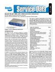
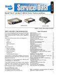
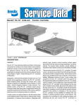
Installation
Instructions
LED lights
illuminate
Diagnostic
Trouble
Codes
(10 locations
in total)
BENDIX® RDU™ REMOTE DIAGNOSTIC UNIT
The Bendix® RDU™ (Remote Diagnostic Unit) is a diagnostic
tool providing the technician with a visual indication of Antilock
Braking System (ABS) component Diagnostic Trouble Code
(DTC) information. The RDU™ unit can be used on Bendix®
ABS-equipped semi-tractors, straight trucks, coaches, and
buses. Additionally, the RDU™ unit provides a method for
clearing the ABS component diagnostic trouble codes from
Bendix® ABS controllers and allows the technician to selfconfigure the ABS ECU on Bendix® EC-17™, EC-30™, and
EC-60™ ABS controller ECUs.
Patents Pending
FIGURE 1 - THE BENDIX® REMOTE DIAGNOSTIC UNIT
The RDU™ unit is specifically designed for use with Bendix®
ABS and Bendix makes no claims for its operation and/or
usability with other brands of ABS systems.
Located on
Dash Panel
DEVICE FEATURES
The RDU™ remote diagnostic unit attaches to the 9 pin
diagnostic connector in the cab of the vehicle. An adapter
cable (Bendix part number 801872) is available to connect
the RDU™ tool to vehicles with a 6-pin diagnostic connector.
(Note: An adapter is required when the vehicle
has a 6-pin connector.)
FIGURE 2 - TYPICAL VEHICLE DIAGNOSTIC
CONNECTOR LOCATIONS (J1708/J1587, J1939)
The RDU™ tool allows the technician to:
LED Diagnostic Trouble Codes
• Troubleshoot ABS system component problems using
LFT RHT DRV ADD STR VLT -
Diagnostic Trouble Code reporting via LEDs.
• Reset Diagnostic Trouble Codes on Bendix® ABS ECUs
by holding a magnet over the reset in center of RDU™ tool
for less than 6 seconds.
• Enter the Self-Configuration Mode used by Bendix® ABS
If the ABS ECU has no active Diagnostic Trouble Codes,
only the green LED will remain illuminated.
If the ABS ECU has at least one active Diagnostic Trouble
Code the RDU™ tool displays the first diagnostic trouble code
by illuminating the red LEDs, indicating the malfunctioning
ABS component and its location on the vehicle. (See Figure
3.) If there are multiple diagnostic trouble codes on the ABS
system, the RDU will display one diagnostic trouble code
first, then once that Diagnostic Trouble Code has been
repaired and cleared, the next code will be displayed.
Left
Right
Drive Axle
Additional
Steer Axle
Power
ECU SEN MOD TRC -
ABS Controller
Wheel Speed
Sensor
Pressure Modulator
Valve
Traction Control
LEDs
Green
VLT
Red
SEN
STR
RHT
Example: If the Diagnostic
Trouble Code is "Right
Steer Axle Sensor", the
RDU™ unit will display one
green and three red LEDs
ECUs by holding a magnet over the reset area for greater
than 6 seconds but less than 30 seconds.
OPERATION
See Figure 2 for typical vehicle connector locations.
When the RDU™ unit is plugged into the diagnostic connector,
all the LEDs will illuminate, and the green LED will flash 4
times to indicate communications have been established.
Located Under
Dash Panel
Or
FIGURE 3 - DIAGNOSTIC TROUBLE CODES
Typical Combination Diagnostic Trouble Codes are:
•
•
•
•
•
•
•
•
Right steer sensor
Left steer sensor
Right drive sensor
Left drive sensor
Right additional sensor
Left additional sensor
Right steer modulator
Left steer modulator
•
•
•
•
•
•
•
Right drive modulator
Left drive modulator
Right additional modulator
Left additional modulator
Traction modulator
ECU
Engine serial
communication
1
• MOD red LED illuminated, shows the "Common"
connection of one or more modulators is shorted to battery
or ground
• VLT (Flashing indicates either over- or under-voltage
condition)
To pinpoint the root cause and to ensure the system
diagnostic trouble code is properly corrected the first time,
additional troubleshooting may be necessary.
RESET FUNCTION
The magnetic reset switch is located in the center top of the
RDU™ unit. Activation requires a magnet with 30 gauss
minimum.
The reset operations are:
1. If the magnet is held over the switch for less than 6
seconds the "clear diagnostic trouble codes" command
is sent.
2. If the magnet is held over the switch for more than 6 seconds, but less than 30 seconds, the Bendix® ABS "selfconfiguration command" is sent.
Additionally, it is recommended at the end of any inspection
that the user switches off and restores the power to the
ABS ECU, then check the ABS Warning Lamp operation
and RDU ™ tool to see if they indicate any remaining
Diagnostic Trouble Codes.
ECU COMMUNICATION PROBLEMS
If the ABS ECU does not respond to the RDU™ unit’s request
for diagnostic trouble codes, the RDU™ unit will illuminate
each red LED in a clockwise pattern. This pattern indicates
the loss of communication and will continue until the ABS
ECU responds and communication has been established.
Possible sources of communication problems are:
1. A problem with the J1587 link at the in-cab off-board
diagnostic connector (9 or 6 Pin)
2. The ECU does not support PID194
3. No power is being supplied to the ECU and/or the
diagnostic connector
4. The J1587 bus is overloaded with information and the
RDU can not arbitrate access
5. A malfunctioning RDU™ unit
For more information on troubleshooting and repairing ABS
Diagnostic Trouble Codes, and Self-Configuration, see the
current Bendix Service Data sheet. Service Data sheets can
be downloaded from www.bendix.com or ordered from your
local authorized Bendix parts outlet.
ABS Controller Models . . . . . . . . . See Service Data Sheet
EC-16™ controller . . . . . . . . . . . . . SD-13-4787 (BW1726)
EC-17™ controller . . . . . . . . . . . . . SD-13-4788 (BW1910)
EC-30™ controller . . . . . . . . . . . . . SD-13-4815 (BW2160)
Bendix® Gen. 4™ & Gen. 5™ABS . SD-13-4746 (BW2261)
WARNING! PLEASE READ AND FOLLOW
THESE
INSTRUCTIONS
TO
AVOID
PERSONAL INJURY OR DEATH:
When working on or around a vehicle, the following
general precautions should be observed at all times.
1. Park the vehicle on a level surface, apply the
parking brakes, and always block the wheels.
Always wear safety glasses.
2. Stop the engine and remove ignition key when
working under or around the vehicle. When
working in the engine compartment, the engine
should be shut off and the ignition key should be
removed. Where circumstances require that the
engine be in operation, EXTREME CAUTION should
be used to prevent personal injury resulting from
contact with moving, rotating, leaking, heated or
electrically charged components.
3. Do not attempt to install, remove, disassemble or
assemble a component until you have read and
thoroughly understand the recommended
procedures. Use only the proper tools and observe
all precautions pertaining to use of those tools.
4. If the work is being performed on the vehicle’s air
brake system, or any auxiliary pressurized air
systems, make certain to drain the air pressure from
all reservoirs before beginning ANY work on the
vehicle. If the vehicle is equipped with an AD-IS™
air dryer system or a dryer reservoir module, be
sure to drain the purge reservoir.
5. Following
the
vehicle
manufacturer’s
recommended procedures, deactivate the electrical
system in a manner that safely removes all electrical
power from the vehicle.
6. Never exceed manufacturer’s recommended
pressures.
7. Never connect or disconnect a hose or line
containing pressure; it may whip. Never remove a
component or plug unless you are certain all
system pressure has been depleted.
8. Use only genuine Bendix ® replacement parts,
components and kits. Replacement hardware,
tubing, hose, fittings, etc. must be of equivalent
size, type and strength as original equipment and
be designed specifically for such applications and
systems.
9. Components with stripped threads or damaged
parts should be replaced rather than repaired. Do
not attempt repairs requiring machining or welding
unless specifically stated and approved by the
vehicle and component manufacturer.
10. Prior to returning the vehicle to service, make
certain all components and systems are restored
to their proper operating condition.
11. For vehicles with Antilock Traction Control (ATC),
the ATC function must be disabled (ATC indication
lamp should be ON) prior to performing any vehicle
maintenance where one or more wheels on a drive
axle are lifted off the ground and moving.
EC-60™ controller . . . . . . . . . . . . . SD-13-4863 (BW4863)
S-1425 © 2005 Bendix Commercial Vehicle Systems LLC 4/2005 Printed in U.S.A. All Rights Reserved.
2