1
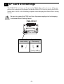
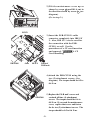
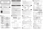
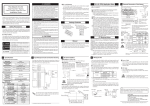
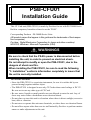
PSB-CFU01
Installation Guide
This CF Card unit (PSB-CFU01) is made by Pro-face for use with PS-2000B Series
Built-in computers, hereafter referred to as the "PS-B".
Corresponding Products : PS-2000B Series Units
(All product names that appear in this guide are the trademarks of their respective companies)
Pro-face: Digital Electronics Corporation (in Japan and other countries)
MS-DOS, Windows: Microsoft Corporation (USA)
WARNINGS
WARNINGS
• Be sure to check that the PS-B’s power is disconnected before
installing the unit, in order to prevent an electrical shock.
• Do not attempt to modify or open the PSB-CFU01, due to the
dangers of shock and fire.
• When installing the PSB-CFU01, be sure to read the following
“3. Installation” section’s information completely to insure that
the unit is correctly installed.
To Prevent Accidents
• Since the PSB-CFU01 is a precision instrument, be sure it is neither hit by nor
pressed strongly against another object.
• The PSB-CFU01 is designed to use only CF Cards whose rated voltage is DC 5V.
Be sure not to use any other type of CF Card.
• Be sure water, liquids or metal particles are not allowed to enter the unit. Any of
these may cause either a breakdown or an electrical shock.
• Do not place or store this unit in a location where there is direct sunlight, excessive
heat, dust or vibration.
• Do not store or operate this unit near chemicals, or where there are chemical fumes.
• Do not allow anyone other than service staff trained by Pro-face to perform maintenance or make adjustments to this unit.
-1-
• Do not use the PSB-CFU01 in locations where corrosive gasses are present.
• To prevent damage to file data, be sure to shut down the PS-B unit's OS before
turning OFF the main power.
Package Contents
Please check that the following items are included in your package.
PSB-CFU01 (1)
Attachment Screws (2)
Installation Guide (this guide)
Digital has taken the utmost care to insure the quality of this product when it was
shipped, however, should, for any reason, problems or damage have occurred during
shipping, please contact your Pro-face representative immediately for service.
1
Hardware Specifications
Features
Rated Voltage
Compatible CF Cards
5V (supplied from the PS-B)
Cards based on CFA standard Type 1
(Only 5V cards supported)
CF Card Interface
Weight
True-IDE mode
Approx. 150g (without a CF card)
Environment
0oC to 50oC
-10oC to +60oC
10%RH to 85%RH
(no condensation)
Wet bulb temperature: 29oC or less
Operating Temperature
Storage Temperature
Ambient Humidity
0.1mg/m3 or less
(Non-conductive particles)
Dust
Atmosphere
Vibration Resistance
Free of corrosive gases
19.6m/s2 (10Hz to 25Hz) (When Operating)
X,Y,Z directions for 30 minutes
The environment specifications given here are for a unit installed in a
PS-B.
-2-
2
CF Card Unit Settings
The PSB-CFU01 is factory set for use as the PS-B's Slave drive, however, if the user
desires, this setting can be changed so that the PSB-CFU01 can be used as the PS-B's
Master drive. Refer to the following diagram when changing the Master/Slave Setting
Switch.
Be sure to unplug the PS-B unit from its power supply prior to changing
the Master/Slave Setting Switch.
PSB-CFU01
Master/Slave Setting Switch
Master Setting
Slave Setting
M
M
S
S
(Factory Setting)
-3-
3
Installation
Use the following steps to install the PSB-CFU01 in the PS-B.
WARNINGS
WARNING
Shock Danger! Be sure to unplug the PS-B unit from its power supply prior to installing the PSB-CFU01.
Since the PSB-CFU01 is a precision instrument, be sure it is neither hit
by nor pressed strongly against another object.
Cover
1) Lay the PS-B unit on its side and
unscrew the four (4) cover attachment
screws.
2) Slide the cover horizontally in the
direction shown by the arrow (see
diagram) and lift it out from the PSB unit.
(Go to step 3.)
Step 2
Step 1
You can also remove only the maintenance cover and install the CF card unit.
To do this, please perform the following steps.
Maintenance Cover
1) Loosen the two (2) maintenance cover
attachment screws.
-4-
b
2) Tilt the maintenance cover up as
shown by arrow a and lift it out in
the direction shown by arrow b (see
diagram).
(Go to step 3.)
a
IDE I/F 1
3) Insert the PSB-CFU01's cable
connector completely into IDE I/F
2. Also, IDE I/F 1 can be used for
the connection with the PSBCFU01, as well. For the
procedures of a CF card insertion
and removal,
4. CF
Card Handling.
PSB-CFU01
Cable
IDE I/F 2
Front of
PS-B unit
4) Attach the PSB-CFU01 using the
two (2) attachment screws. (See
diagram) The torque should be 0.5 to
0.6 N•m.
PSB-CFU01
-5-
5) Replace the PS-B unit's cover and
reattach all four (4) attachment
screws. The torque should be 0.6 to
0.8 N•m. If you used the maintenance
cover, replace that cover and fasten
the its two (2) attachment screws. The
torque should be 0.5 to 0.6 N•m.
4
CF Card Handling
CAUTIONS
CF Card Handling
• The following CF Cards are manufactured by the Digital Electronics
Corporation and are recommended for use with this unit; GP077-CF20,
and GP077-CF30. The performance of this CF Card Unit cannot be
guaranteed when using another manufacturer’s CF Card.
• Be sure to use a CF Card with a rated voltage of DC 5V.
• Be sure to follow the instructions given below to prevent the CF
Card’s internal data from being destroyed or a CF Card malfunction
from occurring:
• DO NOT bend the CF Card.
• DO NOT drop or strike the CF Card against another object.
• Keep the CF Card dry.
• DO NOT touch the CF Card's connector holes or the CF card unit's
connector pins.
• DO NOT disassemble or modify the CF Card.
When using the CF Card Unit and the CF Card
• Prior to inserting the CF Card, be sure to confirm that the rear and the
front of the CF Card are correctly oriented, and that the CF Card connector position is correct. If the CF Card is inserted incorrectly, the
CF Card, its internal data, and the CF card unit may be damaged.
• Prior to inserting or removing the CF Card, be sure to turn OFF the
PS-B to prevent damaging file data and stopping OS. When operating,
PSB-CFU01 regards the CF Card as the hard disk.
• Never turn OFF or reset the PS-B while accessing the CF Card to prevent damaging file data. Also, be sure to shut down the PS-B unit's
OS before turning OFF the main power.
Data Overwrite Limit
The CF Card has a data overwrite limit of approximately 100,000 times. Therefore,
be sure to back up all CF Card data regularly to another storage media.
(100,000 times assumes the overwriting of 500KB of data in DOS format)
CF Card Insertion and Removal
• Familiarize yourself with the differences between the top and bottom surfaces of
the CF Card. Also, be sure to read the CF Card's operation manual to ensure that
the CF Card is properly oriented when it is inserted (i.e. whether the top of the card
is up or down etc.)
• When connecting the PSB-CFU01 cable with the IDE I/F 1, insert/remove the CF
card from the PSB-CFU01 outside the PS-B, not inside the PS-B.
-6-
Inserting the CF Card
1) Turn OFF the PS-B unit's main power, and uncover the PS-B's cover/maintenance cover. For the procedures of the uncover,
3. Installation.
2) Loosen the CF card stopper attachment screw, and unlock the CF card stopper as
the following arrow shows. (see diagram)
PSB-CFU01
CF Card Stopper Attachment Screw
CF Card Stopper
Eject Button
3) Hold the CF Card by the end opposite the connector and insert it into the CF
Card slot until the eject button is pushed forward. If the card seems to jam or
does not move smoothly, remove the CF Card. Confirm that the card is properly
oriented.
4) Pivot (Push) the eject button 90o to the right.
5) Reset the CF card stopper, and fasten the CF card stopper attachment screw. The
torque should be 0.5 to 0.6 N•m.
6) Replace the PS-B unit's cover and reattach all four (4) attachment screws. If you
used only the maintenance cover, replace that cover and fasten the its two (2)
attachment screws.
Removing the CF Card
1) Turn OFF the PS-B unit's main power, and uncover the PS-B's cover/maintenance cover. For the procedures of the uncover,
3. Installation.
2) Loosen the CF card stopper attachment screw, and unlock the CF card stopper as
the following arrow shows. (see diagram)
PSB-CFU01
CF Card Stopper Attachment Screw
CF Card Stopper
Eject Button
3) Pivot the eject button outwards and push it in. Grasp the edges of the CF Card
with your fingers, and slowly pull it out.
4) Pivot (Push) back the eject button 90o to the right.
5) Reset the CF card stopper, and fasten the CF card stopper attachment screw. The
torque should be 0.5 to 0.6 N•m.
6) Replace the PS-B unit's cover and reattach all four (4) attachment screws. If you
used only the maintenance cover, replace that cover and fasten the its two (2)
attachment screws.
-7-
5 Hardware Setup
4
1) Install the PSB-CFU01 in the PS-B. Refer to 3 Installation for details. If the
PSB-CFU01 is already installed, this step is not necessary.
2) Connect a keyboard to the PS-B.
3) Turn on the PS-B unit's power supply.
• Normally, use the factory (initial) settings.
• Your PS-B unit's system data screen menus may differ slightly from these
due to installation of newer software.
• The following explanation uses the PS-B unit's factory settings.
4) When the start-up screen appears, press your PC’s [DEL] key.
The Setup utility will start. Select [Standard CMOS Features], then [IDE Primary Master] or [IDE Primary Slave] depending on the settings of the Master/
Slave setting switch. The following screen will appear.
(When selecting [IDE Primary Master])
Phoenix- AwardBIOS CMOS Setup Utility
IDE Primary Master
IDE HDD Auto-Detection
[Press Enter]
IDE Primary Master
Access Mode
[Auto]
[Auto]
Capacity
0 MB
Cylinder
Head
Precomp
Landing Zone
Sector
0
0
0
0
0
Item Help
Menu Level
To auto-detect the
HDD's size, head...on
this channel
↑↓→←:Move Enter:Select +/-/PU/PD:Value F10:Save ESC:Exit F1:General Help
F5:Previous Values F6:Fail-Safe Defaults F7:Optimized Defaults
5) Confirm whether "AUTO" is selected for IDE Primary Master/IDE Primary
Slave. Also, confirm whether "AUTO" is selected for the [Access Mode]. If
AUTO is not selected, change these settings to AUTO. If AUTO is selected in
both, disk parameters will be automatically read when the PS-B is turned ON.
The factory setting is AUTO and recommended for most users.
6) After all changes are made, press the ESC key and select [Save & EXIT Setup]
to save the settings. The OS will then start.
Note
Please be aware that Digital Electronics Corporation shall not be held liable by the user
for any damages, losses, or third party claims arising from the uses of this product.
Digital Electronics Corporation
8-2-52 Nanko Higashi, Suminoe-ku, Osaka 559-0031, Japan
URL: http://www.pro-face.com/
© 2002 Digital Electronics Corporation
-8-