Transcript
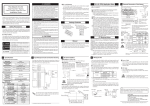
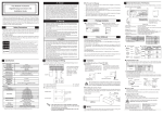
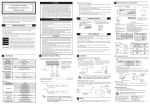
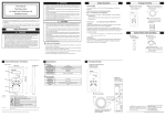
Thank you for purchasing Pro-face's "Flex Network I/O Unit
16-point Input Sink • Source Type" (FN-X16TS41) unit. To
ensure correct use of this unit's functions and features, be sure
to carefully read this installation guide and the Flex Network
DIO Unit User Manual (downloaded from Pro-face web site).
Safety Precautions
This guide contains a variety of safety markings for safe and
correct operation of this unit. Please read this installation guide
and any related manuals carefully to fully understand how to
correctly use this unit's functions.
Safety Symbols
This guide uses the following symbols for important information related to the safe and correct operation of this unit. Please
pay attention to these symbols and follow all instructions given.
Safety symbols and their meanings:
A potentially hazardous situation that
WARNING could result in serious injury or even death
if instructions are not followed.
CAUTION
Specifications
DC24V
DC20.4 to DC28.8V
Rated Voltage
Rated Voltage Range
Allowable Voltage
Interruption
Power Consumption
• Communication cables or I/O signal lines must be wired separately from the
main circuit (high-voltage, large-current) line, high-frequency lines such as
inverter lines, and the power line. Otherwise, a malfunction may occur due
to noise.
• This unit must be properly installed according to directions in the installation
guide and user's manual. Improper installation may cause the unit to malfunction, or fail.
• This unit must be properly wired according to directions in the Installation
Guide and User Manual. Improper wiring may cause a malfunction, failure
or electric shock.
• Do not allow foreign substances, including chips, wire pieces, water, or liquids to enter inside this unit's case. Otherwise, a malfunction, failure, electric shock, or fire may occur.
• When disposing of this unit, handle it as an industrial waste.
Input Circuit Connection Drawing
The input area shown here shows the connection wiring to a
sink output type device. (The dotted line represents the connection wire to the source output type unit.)
10ms or less (Power Supply: DC24V)
1.5W or less
AC1,500V 10mA 1minute
(between power/Input and Output, and FG terminals)
DC500V at 10M Ω or higher
(between power/Input and Output, and FG terminals)
30A or less
Voltage Endurance
Insulation Resistance
In-rush Current
Flex Network I/O Unit
16-point Input Sink •
Source Type (FN-X16TS41)
Flex Network I/O Unit
16-point Input Sink • Source Type
Installation Guide (this guide)
CAUTIONS
3
Electrical (Control section)
Package Contents
Manual
You can download the Flex Network DIO Unit User Manual
from Pro-face's web site.(http://www.pro-face.com/)
If you require the manual on another type of media (CD-ROM,
etc.), please contact your local Pro-face distributor.
4
This procedure installs the unit on a 35mm DIN rail.
Installation
Removal
Hook the I/O unit's top face
groove over the top edge of the
DIN rail. Next, push the bottom
of the I/O unit forward until the
attachment hook clicks into
place on the DIN rail.
Use a screwdriver to push the
attachment hook down and release the unit. Then, pull the unit
forward and off the rail.
DIN rail
0°C to 55°C
Communication Cable
The Flex Network interface and the I/O unit, or all distributed
I/O units, are connected using a cross wiring system. (T-type
systems cannot be used.)
Use the following models of communication cables.
Flat-head screwdriver
-25°C to +70°C
I/O unit
Be sure that the top and bottom faces of the unit
are facing the correct direction and the unit is installed in a vertical position. Incorrect installation
may prevent heat from dissipating.
Input
Rated Input Voltage
DC24V
Max. Input Voltage
DC28.8V
16
(available for both sink and source types)
No. of Input Points
Input ON Voltage
DC15V or higher
Input OFF Voltage
DC5V or less
Input Impedance
4.1kΩ
OFF-ON
1.5ms or less
ON-OFF
1.5ms or less
No. of Exclusive Use Nodes
Push
down
Installing in a panel:
Create a panel cut for installing the unit, using the dimensions
given below. Secure the I/O unit in place with M4 size screws.
The torque should be 0.5 to 1.3 N•m.
I/O unit center
The I/O unit's power supply should be separated from
the sensor's power supply to prevent the unit from
being affected by external noise.
I/O unit outline
2φ
φ0 4 . 5
.18 ( 0
.0
)
8
Center of DIN rail
1
48.1 to 50.3(1.89 to 1.98)
50.3(1.98)
(98.4 to 100.6(3.87 to 3.96))
*1 Dotted line shows the source output connection.
(Unit: mm/in.)
Order Code
Length
FN-CABLE2010-31-MS
10m
FN-CABLE2050-31-MS
50m
FN-CABLE2200-31-MS
200m
D
C
3.9(0.15)
33(1.30)
B
3.5(0.14)
108(4.25)
Front View
Side View
Factory (Default) settings
Communication speed:
6 Mbps
S-No. (station no.): 0
Bottom View
A: Dip Switches ...................... Set communication speeds and S-No. (first digit).
B: S-No. (station no.) Switch .. Sets S-No. (last digit).
C: Terminal Switch .................. Changes termination ON/OFF. Turns ON only
the unit connected at the end of the communication cable.
D: Status LED ......................... Indicates the unit's current operation status.
Switch Settings
Examples of S-No. (station no.) settings
Dip Switch
Reserved
S-No.
6 ........ 6 Mbps,
12 ...... 12 Mbps
SW3, 4 First ... ON (1),
10h(16)
Last ... OFF (0)
SW3
SW4
S-No. (Station
no.) Setting
OFF(0)
ON(1)
0
Arrow tip Setting values
(0 to F)
ON(1)
ON(1)
F
SW1
SW2
OFF ... Termination OFF,
ON ..... Termination ON
3Fh(63)
Power Cable
• Use as large a cable as possible (up to 1.25 mm2) and be
sure to twist all wire ends before attaching crimp terminals.
• Use the same type crimp terminals as used for the communication cable.
I/O Cable
• Use a cable that is 0.5 to 1.25 mm2 in diameter.
• Use the same type crimp terminals as used for the communication cable.
• Confirm that all I/O unit terminal screws are securely tightened, even if they are not used.
• Do not allow pieces of wire to fall inside the unit.
When preparing the cable wire ends:
- Cover shielded wires with shield tape or with an insulation
tube.
- Use insulated crimp terminals.
- If you use a pressure connection terminal without insulation, cover it with a shield tape or an insulation tube. Cover
uninsulated crimp terminals with shield tape or a tube-type
insulation.
Note
Blue (TR+)
White (TR-)
(35.0(1.38))
Protection Rating
Pollution Level
Input Delay Time
This section describes both the cables and crimp terminals used
for wiring each type of cable. The fastening torque for the terminal screws should be 0.6 to 1.0 N•m. 1or 2 terminals can be
connected to a single terminal screw.
Pro-face
5% RH to 95% RH (non-condensing)
(wet bulb temperature: less than 39°C)
IP20
Pollution Level 2
A
Wiring the I/O
Distributor
Ambient Humidity
(Unit: mm/in.)
This section shows the external dimensions of the I/O unit, part
12.1(0.48)
names and part settings.
The FN-X16TS41 is a CE Marked unit that conforms to EMC
directives EN55011 ClassA, EN61000-6-2, and EN61131-2*2.
<Caution>
While this unit is officially marked as conforming to the relevant
EMC directives, it is the user’s final application of this unit in a
larger system (i.e. the machinery, wiring, control panel, installation
method, etc.) that will determine if this unit maintains or loses this
conformance marking. Therefore, it is strongly advised that the user
investigate and confirm whether their overall system (i.e. all related
machinery and equipment) also conforms with these EMC directives.
*1 The National Electrical Code states that Class 2 power
supplies and Class 2 transformers should not exceed an
output of 30V, and at 8A or less, should not exceed 100VA.
*2 Applies to selected low voltage directives.
5
I/O Unit Installtion
Installing on a DIN rail:
Environmental
Ambient Operating
Temperature
Ambient Storage
Temperature
External Dimensions / Part Names
CE Marking Notes
18.9 16.1
(0.74) (0.63)
2
A potentially hazardous situation that
could result in minor injury or equipment
damage if instructions are not followed.
• Whenever installing, dismantling, wiring, and conducting maintenance or inspections, be sure to disconnect power to this unit to prevent the possibility
of electric shock or fire.
• Do not disassemble or remodel this unit, since it may lead to an electric
shock or fire.
• Do not use this unit in an environment that contains flammable gases since
an explosion may occur.
• Do not use this unit in an environment that is not specified in either the
Installation Guide or User Manual. Otherwise, an electric shock, fire, malfunction or other failure may occur.
• Because of the possibility of an electric shock or malfunction, do not touch
any power terminals while the unit is operating.
The FN-X16TS41 unit conforms to the following standards:
UL508 Electrical Control System for Industry
CAN/CSA-C22.2 No.1010-1
(Safety requirements for electrical equipment for measurement, control and laboratory use)
FN-X16TS41 (UL Registration Model: 2880063-02)
<Notes>
Only use the unit installed with other equipment.
If the unit is installed in an area with no air conditioning
system, be sure to install it in a vertical panel using a DIN
rail or mounting holes. Also, be sure the unit is installed so
it is at least 100 mm away from any adjacent structures or
devices. If these requirements are not met, the heat generated by the unit’s internal components may cause the unit to
fail to meet UL standards requirements.
The power supply unit connected to the I/O unit must be a
UL/c-UL (CSA) approved Class 2 power supply unit or Class
2 transformer*1. When the GLC/LT/GP3000 or multiple I/
O units under load are operated with a single power supply,
the amount of current consumption and full-load current of
the I/O units must be within the rated load of the Class 2
power supply unit or Class 2 power supply transformer. Be
aware that the number of points which can be turned ON
simultaneously may be limited, depending on the amount
of load and load current value.
3.8(0.15)
or less
6.0(0.24)
or less
DANGER
A hazardous situation that could result in
serious injury or even death if instructions
are not followed.
WARNINGS
1
The FN-X16TS41 is a UL/c-UL (CSA) recognized unit. (UL
File No. E195835)
45(1.77)
Flex Network I/O Unit
16-point Input Sink • Source Type
Installation Guide
UL/c-UL (CSA) Application Notes
To Avoid Damage
• Avoid storing or operating this unit in either direct sunlight
or excessively dusty or dirty environments.
• Because this unit is a precision instrument, do not store or
use it in locations where excessive shocks or vibration may
occur.
• Avoid covering this unit's ventilation holes, or operating it
in an environment that may cause it to overheat.
• Avoid operating this unit in locations where sudden temperature changes can cause condensation to form inside the
unit.
• Do not use paint thinner or organic solvents to clean this
unit.
15.1(0.59)
28.2(1.11)
49(1.93)
DANGERS
• An emergency stop circuit and an interlock circuit should be constructed
outside of this unit. Constructing these circuits inside this unit may cause a
runaway situation, system failure, or an accident due to unit failure.
• Systems using this unit should be designed so that output signals which
could cause a serious accident are monitored from outside the unit.
• This unit is designed to be a general-purpose device for general industries,
and is neither designed nor produced to be used with equipment or systems
in potentially life-threatening conditions. If you are considering using this
unit for special uses, including nuclear power control devices, electric power
devices, aerospace equipment, medical life support equipment, or transportation vehicles, please contact your local Flex Network distributor.
Shield wire (SLD)
(Unit: mm/in.)
5.2(0.20)
or more
Please be aware that Digital Electoronics Corporation shall
not be held liable by the user for any damages, losses, or third
party claims arising from the uses of this product.
Head Office
φ3.2(φ0.13)
or larger
Digital Electronics Corporation
8-2-52 Nanko-higashi
Suminoe-ku, Osaka 559-0031 JAPAN
Tel: +81-(0)6-6613-1101 Fax: +81-(0)6-6613-5888
URL: http://www.pro-face.com/
©Copyright 2000 Digital Electronics Corporation. All rights reserved.