1
GENERAL INSTALLATION
Proper installation of the unit is essential for years of safe, reliable operation.
Please read all instructions before installing the unit. Failure to follow these
instructions can cause serious damage to the unit or vehicle and may void
warranties.
Qualifications
The installer must have a firm knowledge of basic electricity, vehicle electrical
systems and emergency equipment.
Keep These Instructions
Keep these instructions in the vehicle or other safe place for future reference.
Advise the vehicle operator of the location.
Unpacking
Inspect contents for shipping damage. If any damage is found alert the carrier
immediately. Contents should include: an amplifier box with wiring pigtail, a "U"
bracket with screws for mounting, and these instructions. Please contact supplier
immediately if any components are missing.
INSTALLER-SELECTABLE OPTIONS
The SS650 and LCS652 have Phaser disable, Two-Tone enable, and Auxiliary Horn
Polarity options that can be selected during installation. An internal jumper on the
printed circuit board inside the amplifier case allows the installer to select these
options. These options should be set before installation of the unit.
Phaser Tone Disable – The Phaser function can be completely disabled by
moving one of the option jumpers inside the amplifier unit from "Extra" position
to the "TD" (Tone Disable) position. When Phaser is disabled, the Manual button
(MAN or MANUAL) will not have any effect on the tone while the siren is in the
YELP mode (in WAIL, it will still change the tone to YELP).
Two-Tone Enable - The Two-Tone function can be enabled by moving one of
the option jumpers inside the amplifier unit from "Extra" to the "Two-Tone"
position. When Two-Tone is enabled, a European Two-Tone (HI-LO) sound
will replace the Phaser sound when the MAN or MANUAL button is pressed
while the siren is in the YELP mode. (The tone will toggle between YELP and
Two-Tone each time the MAN or MANUAL button is pressed).
Auxiliary Horn Polarity - The Auxiliary Input allows activation by an external
source of the Horn function. This input is usually wired into the vehicle horn
switch. The wiring diagram on page 8 shows two connection examples. NOTE:
Permanent disconnection of the vehicle horn is NOT recommended.
The auxiliary input is normally activated by applying a positive voltage to the wire.
To activate by connecting to ground (negative), move the "AUX" option jumper
from the "Pos." pins to the "Neg." pins. (See diagram on next page).
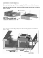
If you would like to disable the Phaser, enable Two-Tone, or change the
Auxiliary polarity proceed with Amplifier Cover Removal below. If you do not
need to set these options, proceed the MOUNTING section on the page 5.
-3-