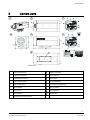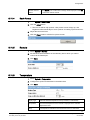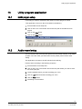
1
CCMC1315-LP / CCMS1315-LP 1/3” 1.3 MP Colour IP Camera Configuration Building Technologies Fire Safety & Security Products Technical specifications and availability subject to change without notice. © 2009 Copyright Siemens Switzerland Ltd We reserve all rights in this document and in the subject thereof. By acceptance of the document the recipient acknowledges these rights and undertakes not to publish the document nor the subject thereof in full or in part, nor to make them available to any third party without our prior express written authorization, nor to use it for any purpose other than for which it was delivered to him. Table of contents 1 Safety..............................................................................................................5 1.1 General safety precautions .............................................................................5 1.1.1 Transport..........................................................................................5 1.1.2 Installation........................................................................................5 1.2 Meaning of symbols ........................................................................................6 2 EU-directives .................................................................................................6 3 Technical data ...............................................................................................7 4 Ordering data...............................................................................................10 5 Package contents........................................................................................10 6 Camera parts ...............................................................................................11 7 Installing the camera ..................................................................................13 7.1 SD Memory Card...........................................................................................13 7.2 Concept of the Network Camera...................................................................13 7.3 Setting Network Camera Environment..........................................................14 7.4 Connecting the Camera and PC by Network ................................................14 7.5 Using the Web-Cam IP manager ..................................................................16 7.6 Browser settings............................................................................................17 8 Getting started.............................................................................................19 8.1 Login..............................................................................................................19 8.2 Using the Live Player - Web..........................................................................19 8.3 Using a RTSP player.....................................................................................21 8.4 Function support............................................................................................23 9 Configuration...............................................................................................24 9.1 Compression .................................................................................................24 9.1.1 Bandwidth requirements ................................................................26 9.2 Network settings............................................................................................27 9.2.1 Basic ..............................................................................................27 9.2.2 DDNS.............................................................................................29 9.2.3 FTP Server.....................................................................................30 9.3 Image parameters .........................................................................................30 9.3.1 Basic ..............................................................................................30 9.3.2 Auto Patrol .....................................................................................33 9.3.3 Mask Zone .....................................................................................33 9.3.4 Cropping ........................................................................................34 9.3.5 OSD ...............................................................................................35 9.4 Alarm .............................................................................................................36 9.4.1 Alarm..............................................................................................36 9.4.2 Audio Upload .................................................................................39 9.4.3 Alarm Server ..................................................................................39 9.5 Record...........................................................................................................40 9.5.1 FTP Recording...............................................................................40 9.5.2 SD Recording.................................................................................43 9.5.3 E-Mail Recording ...........................................................................45 3 Building Technologies Fire Safety & Security Products CCMx1315-LP Configuration Manual EN 05.05.2009 9.5.4 NAS Recording ..............................................................................48 9.6 Audio .............................................................................................................50 9.7 Date/Time ......................................................................................................51 9.8 Access protection ..........................................................................................52 9.8.1 Administrator ..................................................................................52 9.8.2 User list ..........................................................................................53 9.9 Firewall ..........................................................................................................53 9.9.1 IP Address Filter ............................................................................53 9.9.2 Forbidden Ports .............................................................................54 9.9.3 Forbidden Protocol.........................................................................55 9.10 System...........................................................................................................55 9.10.1 Setting ............................................................................................55 9.10.2 Firmware Update ...........................................................................55 9.10.3 Configuration..................................................................................56 9.10.4 Back Focus ....................................................................................57 9.10.5 Remote...........................................................................................57 9.10.6 Temperature...................................................................................57 9.11 Logbook.........................................................................................................58 9.12 Licence information .......................................................................................58 10 Utility program application.........................................................................59 10.1 NAS player setup ..........................................................................................59 10.2 Audio record setup ........................................................................................59 10.3 Firmware update setup..................................................................................60 11 Maintenance.................................................................................................61 12 Disposal........................................................................................................61 13 Index .............................................................................................................62 4 Building Technologies Fire Safety & Security Products CCMx1315-LP Configuration Manual EN 05.05.2009 Safety 1 Safety 1.1 General safety precautions z Read the general safety precautions before installing, configuring and operating the device. z Keep this document for reference. z Please also take into account any additional country-specific, local safety standards or regulations concerning project planning, operation and disposal of the product. z Follow all warnings and instructions marked on the device. Liability claim 1.1.1 z Do not make any changes or modifications to the device unless they have been approved by the manufacturer. z Use only spare parts and accessories that have been approved by the manufacturer. Transport Damage during transport 1.1.2 z Keep the packaging material for future transportation. z Do not expose the device to mechanical vibrations or shocks. Installation z It is recommended that all preparatory work (e.g. fitting of accessories) be carried out in a workshop prior to final installation. Radio interference with other devices in the environment z When handling modules that are susceptible to electrostatic discharge, please observe the ESD guidelines. Damage due to unsuitable mounting location z The environmental conditions recommended by the manufacturer must be observed. See section “Technical data”. z Do not operate the device in dusty places. z Do not expose the device to mechanical vibrations or shocks. 5 Building Technologies Fire Safety & Security Products CCMx1315-LP Configuration Manual EN 05.05.2009 EU-directives z Protect the device against moisture. z Place the unit on a stable surface that will hold its weight. z The mounting surface must be solid and non-combustible. z Do not operate the device close to sources of powerful electromagnetic radiation. Danger of electrical shock due to incorrect connection 1.2 z Connect the device only to power sources with the specified voltage. Voltage supply requirements can be found on the mains adapter. z Make sure the device is permanently connected to the electricity supply; a readily accessible disconnect device must be provided. z This device is designed to work with DC 12 V / AC 24 V-systems or PoE. Do not connect the device to any other power systems. Meaning of symbols NOTICE Malfunctioning may result. Tips and information. 2 EU-directives This product complies with the requirements of the following European directives. The EU declaration of conformity is available to the responsible agencies at: Siemens Building Technologies Fire & Security Products GmbH & Co. oHG 76181 Karlsruhe Germany European Directive 2004/108/EC „Electromagnetic Compatibility” Compliance with the European Directive 2004/108/EC has been proven by testing according to the following standards: Emitted interference: EN 61000-6-3 EN 55022 Class B Interference resistance: EN 50130-4 6 Building Technologies Fire Safety & Security Products CCMx1315-LP Configuration Manual EN 05.05.2009 Technical data 3 Technical data Image system Image sensor 1/3" progressive CCD (EXview HAD), 1.3 megapixels Pixels Full scanning mode: 1280 (H) X 960 (V) Compression MJPEG / MPEG4 Image frame rate SXGA (1280 x 960) at 12 ips max. (MJPEG only) VGA (640 x 480), QVGA (320 x 240) at 25 ips max. Cropping window Simultaneous video transmission of up to 5 independent cropping windows, freely configurable in size and position at 5 ips max. (MJPEG mode only) Video outputs 1 Vpp (75 Ω BNC composite video) CVBS or IP video alternatively selectable by switch Electronics Synchronisation Internal Signal/noise ratio > 50 dB Lens CS mount Gamma correction 0.45 / 1 Minimum illumination CCMC1315-LP: 0.4 lx (F1.2, AGC On) CCMS1315-LP: Colour 0.4 lx (F1.2, AGC On); BW 0.2 lx (AGC On) White balance control Auto (2500 – 10000 K) / Manual (1500 – 15000 K) / Preset Shutter speed 1/25 – 1/10,000 s; support of long shutter up to 4 s max. Back light compensation On/Off, BLC1 - BLC6 (BLC) Audio Two-way audio; full-duplex, G.726 (integrated microphone) Alarm inputs 1, 1 x B/W switch in Alarm outputs 1 Telemetry protocol RS485 SD card slot 2 GB SD-RAM included in scope of delivery Microphone Internal Motion detection 1 MD window (selectable size & position) with 3 sensitivity levels 7 Building Technologies Fire Safety & Security Products CCMx1315-LP Configuration Manual EN 05.05.2009 Technical data Network Network connections Ethernet 10/100 Base-T Compression JPEG / MPEG4 (dual-streaming) Resolution MJPEG: VGA (640 x 480 pixels) / QVGA (320 x 240 pixels) at 25 ips max. MJPEG: SXGA (1280 x 960 pixels) at 12 ips max. MPEG4: VGA (640 x 480 pixels) / QVGA (320 x 240 pixels) at 25 ips max. Image quality setting 5 levels (compression level) Audio function Two-way mono audio; full-duplex Protocols TCP/IP, UDP, HTTP, SMTP, DNS, DHCP, NTP, ARP, ICMP, FTPc, FTPs, DDNS, RTP (RTCP, RTSP), IGMP v3, UPnP, NFS, CIFS Web browser IE browser 6.0 or above I/O connector Network port RJ45 with control LEDs Video outputs BNC (CVBS out alternatively selectable by switch) AI Lens connector 1 x 4-pin jack (located on side) Audio in & out connector 3.5 mm phone jack Alarm connector 2 x alarm in / 1x alarm out Power connector 3-pin spring terminal LED Status, network link RS485 2-pin spring terminal Power supply Power requirements 12 V DC / 24 V AC, 50 Hz or PoE Power consumption CCMC1315-LP: < 7 W CCMS1315-LP: < 8.5 W Power connector Spring terminal Environment Ambient temperature, -10 to 50ºC operating Operating humidity 80 % RH or less Ambient temperature, -20 to 60ºC storage 8 Building Technologies Fire Safety & Security Products CCMx1315-LP Configuration Manual EN 05.05.2009 Technical data Mechanism Dimensions (L x W x H) 150 x 66 x 64 mm Weight 550 g 9 Building Technologies Fire Safety & Security Products CCMx1315-LP Configuration Manual EN 05.05.2009 Ordering data 4 Ordering data Type Art No. Description Weight CCMC1315-LP S54561-C80-A1 1/3” 1.3 MP Colour IP Camera 0.55 kg 12 V DC / 24 V AC, 50 Hz or PoE CCMS1315-LP S54561-C80-A2 1/3” 1.3 MP Day/Night IP Camera 0.55 kg 12 V DC / 24 V AC, 50 Hz or PoE Accessories, not included in delivery CLVD1316/3-8 S54561-B300-A1 1/3" Megapixel varifocal lens, direct- 0.08 kg drive iris, F1.0, 3 – 8 mm CLVM1316/3-8 S54561-B301-A1 1/3" Megapixel varifocal lens, 0.07 kg manual iris, F1.0, 3 – 8 mm CLVD1316/5-50 S54561-B302-A1 1/3" Megapixel varifocal lens, direct- 0.08 kg drive iris, F1.4, 5 – 50 mm CLVM1316/5-50 S54561-B303-A1 1/3" Megapixel varifocal lens, 0.06 kg manual iris, F1.4, 5 – 50 mm 5 Package contents z CCD IP camera z Documentation CD z Utilities CD z Installation instruction (English, German, French, Spanish, Italian) z SD card (2 GB) z Hexagonal wrench z Torx wrench T6 z Lens connector 10 Building Technologies Fire Safety & Security Products CCMx1315-LP Configuration Manual EN 05.05.2009 Camera parts 6 Camera parts A B C F D G E Camera parts 1 Back-focus adjust ring 10 Digital I/O terminal 2 Back-focus lock screw 11 IP/TV selection 3 RJ45 Ethernet connector 12 SD card slot 4 Audio input (φ3.5mm) 13 SD card protection 5 Audio out (φ3.5mm) 14 1/4” inch tripod mount hole 6 SW for default 15 BNC connector 7 SW for reset 16 IRIS connector 8 Power indicator 17 Microphone 9 DC12V/AC24V power terminal 11 Building Technologies Fire Safety & Security Products CCMx1315-LP Configuration Manual EN 05.05.2009 Camera parts Digital I/O terminal GND 1. External alarm input-2 AI2 2. Becoming BW/CL enforced input when the Digital Input Mode is set to ‘BW Mode’ in the Configuration/Alarm menu. See page [J 36] A0 AI2 AI1 GND RS485 COM GND RS485- / + RS485 signal output port for telemetry control COM Alarm output port AO GND External alarm input-1 Al1 3 4 DC Auto Iris port 2 1 Power IN connector PIN 1 Damp - PIN 2 Damp + PIN 3 Drive + PIN 4 Drive WHITE: Power - POWER DC12V / AC24V BLACK: Power + Video output GND Video Signal Output Composite video output IP Video out through Ethernet TV BNC composite video out for installation connector DC 12V AC 24V IP/TV switch purpose IP TV NOTE: After switching between IP and TV the camera has to be restarted Default/Reset DEFAULT Return to factory default by pressing button for 5 seconds RESET System re-start 12 Building Technologies Fire Safety & Security Products CCMx1315-LP Configuration Manual EN 05.05.2009 Installing the camera 7 Installing the camera 7.1 SD Memory Card Please install the SD memory card before switching on the camera as the system can not detect the insertion of an SD card during operation. 7.2 z There is a limit to the number of rewrites that are possible with the SD memory card. Replacing the SD memory card when performing periodic maintenance of the camera is recommended. z The camera supports the following SD memory cards. Do not use memory cards with other specifications. SD memory card: 64, 128, 256, and 512 MB, 1 or 2 GB SD memory cards (3.3 V) supported. z Images may not be recorded or read correctly if an unsupported SD memory card is used with the camera. z Carefully read the manual, precautions on use, and any other information supplied with a purchased memory card. z Do not use a memory card containing the data recorded by another device with the camera as this may result in the camera not functioning correctly. z Do not modify, overwrite the data, or change the folder name of an SD memory card as this may result in the camera not functioning correctly. z Data recorded with the camera do not comply with the image file format Exit and the DCF standard. If the SD memory card is to be removed to play images, use a personal computer to play the images. Other devices may not be capable of doing so. Concept of the Network Camera The camera can be used in various indoor environments. It can deliver video images and audio in real time using the Internet or an intranet. The camera is equipped with Ethernet (RJ-45) 10BASE-T/100BASE-TX network interfaces. Ethernet Hub PC 13 Building Technologies Fire Safety & Security Products CCMx1315-LP Configuration Manual EN 05.05.2009 Installing the camera 7.3 Setting Network Camera Environment Equipment required for a network camera monitoring system: z Administrator's personal computer The personal computer that is given all authorities for setting, operating, monitoring and other functions with the network camera is called the "administrator's personal computer" in this manual. z Recommended personal computer operating conditions ‒ ‒ ‒ ‒ Operating system: Windows Vista or XP Internet Explorer Version 6.0 or later CPU: Intel Pentium 4.2 GHz or higher Memory: 512 MB or more z Network camera Please purchase the required and appropriate number of cameras corresponding to the desired camera installation locations. z Connection equipment such as a hub and router suiting the network system environment and LAN cable, a Cat 5e LAN cable is recommended. z Camera search application Web-Cam IP Manager (See also page [J 16].) Install this application from the Utilities CD supplied as an accessory. ‒ Install the Web-Cam IP Manager Version 2.0 (Web IP Manager.exe) if all the units are located in the same network segment. ‒ Install the Web-Cam IP Manager Version 3.0 (IPFinder.exe) if the units are not located in the same network segment. 7.4 Connecting the Camera and PC by Network IP address To connect to the network, the administrator needs to set the network camera IP address. There are two options for setting the IP address: z Entering the IP address manually (factory default) Your camera is set to this mode at the factory with the IP address: 192.168.0.10, so you need to enter this IP number manually to access the camera for the first time. z Obtaining an IP address automatically from the DHCP server If your network uses a DHCP server, you do not need to change the IP address of the camera. But be sure to set DHCP ON/OFF to ON in "Network settings/Basic". 14 Building Technologies Fire Safety & Security Products CCMx1315-LP Configuration Manual EN 05.05.2009 Installing the camera The IP address of the network camera may change when using the DHCP server. In that case it will not be possible to connect the network camera if it is accessed using the previously set IP address. In order to enable permanent access to the network camera, a fixed IP address must be manually assigned to the camera. Please read the instruction manuals for the network system equipment as well as those for the router, hub and modem. When entering the IP address manually, set DHCP ON/OFF to OFF in "Network/Basic Settings" and enter the IP address, subnet mask, default gateway, primary DNS and secondary DNS. Connection Configuration Two configurations are available for connection of network cameras. z Crossover connection z Connection via a hub, switch, or router You do not need to assign an IP address to a hub. The IP address of your camera is set to 192.168.0.10 by default. Set the IP address of your personal computer in the same subnet. (The network segment must be the same segment when directly connecting using a cross cable or connecting through the hub). When connecting more than one camera, connect each camera using the default IP address and change the IP addresses of the second and subsequent cameras to other IP addresses, such as 192.168.0.11. You can also use the LAN port of your broadband router. However, when using the broadband router, if the DHCP server function is set to "ON", turn on the power after connecting the camera with the router. The camera gets the IP address from the router's DHCP server and it may not be 192.168.0.10. For more information, read your computer's user's guide and the user's guide for the broadband router. It is also recommended to set the computer's IP address from the router's DHCP server. Connecting Camera and Personal Computer 1. Connect the LAN cable (straight cable) connected to the camera to the hub. - OR Connect the camera to a personal computer with the power turned on using the LAN cable (cross cable). Connect DC 12 V / AC 24 V to the power terminal. 2. Set the IP address of your personal computer − Set the IP address of your PC to other than 192.168.0.10 (Camera's default IP address). E.g. set the IP address to 192.168.0.20 (and subnet mask to 255.255.255.0). 15 Building Technologies Fire Safety & Security Products CCMx1315-LP Configuration Manual EN 05.05.2009 Installing the camera − For details about the procedure, refer to the user's guide of the personal computer. 3. Test the camera connection using ping. − Start a command prompt. Type ”ping 192.168.0.10”. − If the ”Reply from...” message appears, the connection is correctly established. 4. Enter the camera’s IP address in the address bar of the IE browser. - OR – Search the camera with the ”Web-Cam IP Manager” application. See page [J 16] . 5. Log-in with the administrator ID. See page [J 19] . 7.5 Using the Web-Cam IP manager The Web-Cam IP Manager is an application for searching for network cameras that can currently be viewed from the administrator's personal computer or a user's personal computer, and connecting to those cameras. Use the Web-Cam IP Manager Version 2.0 (Web IP Manager.exe) if all the units are located in the same network segment. Use the Web-Cam IP Manager Version 3.0 (IPFinder.exe) if the units are NOT located in the same network segment. In that case, you must ensure that associated gateway (router) passes the SSDP (Simple Service Discovery Protocol) multicast messages sent by the Web-Cam IP Manager to the network segment where the device is located. To search a camera in the network: 1. Start the Web-Cam IP Manager (The file is included on the utilities CD). Ö The Web-Cam IP Manager program window will open: 16 Building Technologies Fire Safety & Security Products CCMx1315-LP Configuration Manual EN 05.05.2009 Installing the camera 2. Click the Start button. Ö The Web-Cam IP Manager program window will now display a list of all the devices available for communication along with their IP and MAC addresses. Each device's IP address or MAC address is unique. 3. Select the device whose homepage you want to access. 4. Click the Homepage of selected device button. Ö The homepage of the selected camera will appear. Set the personal computer to "Administrator authorization" when using the Web IP Manager. To connect with a camera without using the Web IP Manager, launch the Internet browser, enter the camera’s IP address in the browser bar an press Enter. If a port number other than "80" is set, designate the port number by suffixing it after ":" (e.g. http://192.168.0.10:88). 7.6 Browser settings 1. Launch the Internet Explorer. 2. Select Internet option on the tools menu and click the Security tab. 3. Click the Local intranet icon if the camera is inside the Intranet. - OR Click the Internet icon if the camera is on the Internet. 17 Building Technologies Fire Safety & Security Products CCMx1315-LP Configuration Manual EN 05.05.2009 Installing the camera 4. Click Level Customize and enable the following options in the displayed list: − "ActiveX control and plug in execute" − "Execution of script of ActiveX control marked safe even when script is executed" − "Download of signed ActiveX control" 5. Enable cookies Browser settings when proxy server is used In case a proxy server is used, setting of the browser to bypass the proxy server during communication with the network camera is recommended. 1. Launch the Internet Explorer. 2. Select Internet option on the tools menu. 3. Click Connections tab and then click the button LAN Settings. Ö If the checkbox is not marked: The browser is not set to use a proxy server. Click Cancel and quit setting. Ö If the checkbox is marked, follow the steps: 4. Click Advanced. 5. Enter the IP addresses of the network cameras in the field marked “Do not use proxy server for addresses beginning with…”. 6. Click OK. ● A proxy server protected by a firewall sometimes cannot be connected to the network camera. Consult the network administrator so as to avoid impacts on network camera operations. ● Communication with the network cameras via a proxy server may cause some problem. Install the network cameras after consulting the network administrator. ● When using the network cameras via a proxy server it may take a long time for the images to be displayed after log-in, or the frame rate of the images may be reduced. 18 Building Technologies Fire Safety & Security Products CCMx1315-LP Configuration Manual EN 05.05.2009 Getting started 8 Getting started 8.1 Login 1. Open the Internet Explorer and enter the camera’s default IP address in the browser address bar: 192.168.0.10. 2. If the IP address is unknown use the Web IP Manager to search for the camera. See page [J 16] . 3. The login dialog will appear. 4. Enter the administrator User name and Password. The default settings for the administrator login are "admin" and "admin". NOTICE Important The administrator login allows rewriting of all settings. Change the default administrator user name and password to ensure camera security. See page [J 52] . 5. Click OK. 6. The homepage of the camera will appear. 8.2 Using the Live Player - Web If the Camera Image screen is not displayed, check your browser settings. See page [J 17] . 1. Click the desired image stream (Stream 1 or 2). 2. Control the live stream as described in the table below. 19 Building Technologies Fire Safety & Security Products CCMx1315-LP Configuration Manual EN 05.05.2009 Getting started Play Shows live image Pause Pauses live image Speaker Stops audio input Microphone Stops audio output E E-zoom control See table below. R Remote control (see table below). You can control PTZ functions, move the camera to preset positions and also make lens adjustments such as focus adjustment and zoom in/out. Before using this function, please set the baud rate and address of the telemetry device for control via the RS485 port. 20 Building Technologies Fire Safety & Security Products CCMx1315-LP Configuration Manual EN 05.05.2009 Getting started Remote control X Exit the remote control -/+ Previous / next preset position 0-9 Select a preset position (1-64) ./.. Toggle between 1 and 2 digits C Clear SET Save current position. (Click SET and then click the number for the preset position to be saved. Up to 64 positions can be stored for the network camera.) Arrow keys Use the arrow keys to move the pan/tilt position. (NOTE: Pan/tilt position control is only available if zoom is larger than 1) +/ο / οο * Zoom in / out Focus near / far *NOTE: Not available for this camera type. 8.3 Using a RTSP player To view the MPEG4 streaming media using an RTSP player, you can use one of the following players that support RTSP streaming (Real-Time Streaming Protocol): z QuickTime Player z VLC Media Player The applications can be found on the Utilities CD included with the delivery. VLC Media player Z The VLC media player needs to be installed. 1. Open the VLC media player. 2. Select Media > Advanced Open File, then click the Network tab. Ö The following dialog box will appear. 21 Building Technologies Fire Safety & Security Products CCMx1315-LP Configuration Manual EN 05.05.2009 Getting started 3. Select RTSP then enter the web address. The format is: rtsp://<IP address>:<rtsp_port>/livestream For example: rtsp://192.168.0.194:554/livestream 4. Click Play. Ö The QuickTime live stream window will opened. QuickTime Player Z The QuickTime player needs to be installed. 1. Open the QuickTime player. 2. Select File > Open URL. Ö The following dialog box will appear. 3. Enter the web address. The format is: rtsp://<IP address>:<rtsp_port>/livestream For example: rtsp://192.168.0.194:554/livestream 4. Click OK. Ö The VLC live stream window will open. 22 Building Technologies Fire Safety & Security Products CCMx1315-LP Configuration Manual EN 05.05.2009 Getting started See also Compression [J 24] 8.4 Function support Ezoom OSD Cropping Mask Frame Zone Rate Stream 1 JPEG SXVGA X X X X 12,5 Stream 2 JPEG SXVGA X X X X 12,5 Stream 1 JPEG VGA O O O O 25 Stream 2 JPEG VGA O O O O 25 Stream 1 JPEG QVGA O O O O 25 Stream 2 JPEG QVGA O O O O 25 Stream 1 MPEG4 VGA O O X O 12,5 Stream 2 JPEG SXVGA X X X X 12,5 Stream 1 MPEGg4 QVGA O O X O 12,5 Stream 2 JPEG SXVGA X X X X 12,5 Stream 1 MPEG4 VGA O O X O 25 Stream 2 Jpeg VGA O O O O 25 Stream 1 MPEG4 QVGA O O X O 25 Stream 2 JPEG VGA X X X X 25 Stream 1 MPEG4 VGA X X X X 25 Stream 2 JPEG QVGA O O O O 25 Stream 1 MPEG4 QVGA O O X O 25 Stream 2 JPEG QVGA O O O O 25 23 Building Technologies Fire Safety & Security Products CCMx1315-LP Configuration Manual EN 05.05.2009 Configuration 9 Configuration NOTICE Important The settings will not be reflected unless the Save button is clicked. 9.1 Compression 1. Select Compression. 2. Configure the options as described in the tables below. 3. Click Save. There are two streams available for selection. Stream 1 can be set to JPEG and MPEG4, but only JPEG is available for Stream 2. Image Mode JPEG MPEG4 Resolution Higher resolution results in larger image sizes. 640 x 480 and 320 x 240 1280 x 960 (SXVGA)/640 x 480 (VGA)/320 available. x 240 (QVGA) Compression Sets quality of images. The size of image files Ratio (JPEG files) varies in accordance with – compression ratio. Select “Low” for highest image quality. The file size increases. 24 Building Technologies Fire Safety & Security Products CCMx1315-LP Configuration Manual EN 05.05.2009 Configuration Select “High” for lowest image quality. The file size decreases. Frame Rate Select the desired frame rate. – Bit Rate – Select the desired bit rate. GOP – Default: 29. “29” means 1 I frame plus 28 P frames. You can adjust GOP size between 1 and 64. Resolution Higher resolution results in larger image sizes. 640 x 480 and 320 x 240 1280 x 960 (SXVGA)/640 x 480 (VGA)/320 available. x 240 (QVGA) Multicast Specify the multicast address (e.g. of the switch or router) Address Transfer Type Select “Unicast” or “Multicast”. In “Multicast” mode camera supports IGMP. When selecting “Automatic Connection”, the camera immediately starts Multicasting. RTSP Port Specify the port number you would like to use for RTSP protocol, default Number is 554 VIDEO Port Specify the port number you would like to use for video streaming, Number default is 5000 See also Using a RTSP player [J 21] 25 Building Technologies Fire Safety & Security Products CCMx1315-LP Configuration Manual EN 05.05.2009 Configuration 9.1.1 Bandwidth requirements Resolution Compression Streaming Frame Rate Mb/s Protocol 320x240 High MJPEG 25 fps 0.90 Mb/s 320x240 Mid-High MJPEG 25 fps 1.17 Mb/s 320x240 Standard MJPEG 25 fps 1.36 Mb/s 320x240 Mid-Low MJPEG 25 fps 1.78 Mb/s 320x240 Low MJPEG 25 fps 2.93 Mb/s 640x480 High MJPEG 25 fps 2.47 Mb/s 640x480 Mid-High MJPEG 25 fps 3.32 Mb/s 640x480 Standard MJPEG 25 fps 4.14 Mb/s 640x480 Mid-Low MJPEG 25 fps 6.10 Mb/s 640x480 Low MJPEG 25 fps 6.73 Mb/s 320x240 High MJPEG 10 fps 0.32 Mb/s 320x240 Mid-High MJPEG 10 fps 0.41 Mb/s 320x240 Standard MJPEG 10 fps 0.47 Mb/s 320x240 Mid-Low MJPEG 10 fps 0.60 Mb/s 320x240 Low MJPEG 10 fps 1.00 Mb/s 640x480 High MJPEG 10 fps 0.83 Mb/s 640x480 Mid-High MJPEG 10 fps 1.11 Mb/s 640x480 Standard MJPEG 10 fps 1.42 Mb/s 640x480 Mid-Low MJPEG 10 fps 2.31 Mb/s 640x480 Low MJPEG 10 fps 3.87 Mb/s 1280x960 High MJPEG 10 fps 2.47 Mb/s 1280x960 Mid-High MJPEG 10 fps 2.71 Mb/s 1280x960 Standard MJPEG 10 fps 2.85 Mb/s 1280x960 Mid-Low MJPEG 10 fps 3.15 Mb/s 1280x960 Low MJPEG 10 fps 3.88 Mb/s 320x240 High MJPEG 5 fps 0.8 Mb/s 320x240 Mid-High MJPEG 5 fps 0.23 Mb/s 320x240 Standard MJPEG 5 fps 0.27 Mb/s 26 Building Technologies Fire Safety & Security Products CCMx1315-LP Configuration Manual EN 05.05.2009 Configuration Resolution Compression Streaming Frame Rate Mb/s Protocol 320x240 Mid-Low MJPEG 5 fps 0.3 Mb/s 320x240 Low MJPEG 5 fps 0.55 Mb/s 640x480 High MJPEG 5 fps 0.46 Mb/s 640x480 Mid-High MJPEG 5 fps 0.62 Mb/s 640x480 Standard MJPEG 5 fps 0.79 Mb/s 640x480 Mid-Low MJPEG 5 fps 1.08 Mb/s 640x480 Low MJPEG 5 fps 1.96 Mb/s 1280x960 High MJPEG 5 fps 1.21 Mb/s 1280x960 Mid-High MJPEG 5 fps 1.27 Mb/s 1280x960 Standard MJPEG 5 fps 1.37 Mb/s 1280x960 Mid-Low MJPEG 5 fps 1.57 Mb/s 1280x960 Low MJPEG 5 fps 1.92 Mb/s NOTE: The bandwidth for MPEG4 streaming is selectable and is therefore not listed in table. 9.2 Network settings 9.2.1 Basic 1. Select Network > Basic. 2. Configure the options as described in the table below. 3. Click Save. 27 Building Technologies Fire Safety & Security Products CCMx1315-LP Configuration Manual EN 05.05.2009 Configuration Basic Camera Name Enter your camera name or use the default name. Camera Name ON or OFF Enable Network DHCP The IP address is automatically obtained if you select ON; otherwise, select OFF if you want to setup the network setting manually. IP Address Enter your IP address here if you have selected DHCP off. Subnet Mask Please use the default number: 255.255.255.0 Default Leave blank as default setting. It is not necessary to enter the default Gateway gateway if it is not used. Ask your network administrator for default gateway information. Primary DNS (same as above) Secondary DNS (same as above) Port Stream 1-2, We recommend using the default port; if you need to change the default Cropping 1-5 port, please contact your system administrator. 28 Building Technologies Fire Safety & Security Products CCMx1315-LP Configuration Manual EN 05.05.2009 Configuration UpnP Use UpnP When set to ON, the camera can be detected automatically by the PC. It is not necessary to install the IpFinder program. Audio Output Use Audio Output When set to ON, a voice message of the camera’s IP address can be delivered to an external speaker via the audio output port. Bandwidth Control Port Bandwith Port OFF: The network camera will stream images at the maximum frame rate allowed by the network. ON: The network camera will display images up to the set bandwidth; using a lower bandwidth results in lower frame rates. 9.2.2 DDNS This function is available when registering with the DDNS provider. To transmit the camera’s host name to a DHCP server you have to configure this in the following settings. 1. Select Network Settings > DDNS. 2. Configure the options as described in the table below. 3. Click Save. DDNS Select ON to enable the DDNS function. DDNS Server Select your DDNS server (DnyDNS or DHS). Host Name Enter the host name. Domain Name Enter the domain name. 29 Building Technologies Fire Safety & Security Products CCMx1315-LP Configuration Manual EN 05.05.2009 Configuration 9.2.3 User ID Enter the login user name according to your DDNS provider. Password Enter the login password according to your DDNS provider. Password (Confirm) Confirm the login password. FTP Server 1. Select Network Settings > FTP Server. 2. Configure the options as described in the table below. 3. Click Save. FTP Function Select ON to activate the FTP function. Login ID Enter the login ID. Password Enter the login password. Password Confirm the login password. (Confirm) Max. Select the max. number of simultaneous connections. Simultaneous Connections 9.3 Image parameters 9.3.1 Basic 1. Select Image Parameters > Basic. 2. Configure the options as described in the tables below. 3. Click Save. 30 Building Technologies Fire Safety & Security Products CCMx1315-LP Configuration Manual EN 05.05.2009 Configuration Preset image 4 types of specific application setups can be selected for quick and easy presetting of parameters. Select “OFF” if you want to make individual settings. Automatic 3 types of specific application conditions can be selected. Exposure In “Full Automatic” mode, the shutter speed is set to 1/60 s and the PTZ camera will automatically adjust the aperture according to the amount of outside light. In “Shutter Priority” mode, the shutter speed is adjustable in 22 steps between 1/1 s and 1/10,000 s. In “Manual” mode, the aperture can be set up manually. EV Adjustment Set the offset level to adjust the internal reference brightness level. The higher the level, the brighter the images and the lower the level, the darker the images. Automatic Gain The circuit gain can be selected between "Low", "Mid" and "High”, Control (AGC) where the sensitivity characteristic increases in the same order. Noise at dark will be more noticeable when Auto Gain Control is near "High". When “OFF” is selected, the AGC is not available. NOTE: If sensitivity is still too low after setting Auto Gain control, set the high limit value of the slow speed shutter to further increase sensitivity and thus to enhance image brightness. Shutter Speed Select the desired shutter speed. The network camera will adjust the aperture according to the amount of ambient light. Slow Speed The Slow speed shutter can be turned on if the sensitivity is still not Shutter sufficient under automatic gain condition at dark. The optimum image level can be maintained by appropriate gain and shutter combination 31 Building Technologies Fire Safety & Security Products CCMx1315-LP Configuration Manual EN 05.05.2009 Configuration which are determined automatically inside camera system. If slow speed shutter is activated, the exposure time becomes longer and the frame rate becomes smaller. Blurred images may result with moving objects. Back Light Set an area for backlight compensation. If backlight compensation is Compensation activated, the camera performs the exposure control only within the specified area. Backlight compensation is a function that adjusts the brightness of a selected area to an optimum level. This function is necessary when an auto iris lens tends to close due to an intense light coming from the back of the object in the area to be viewed so that areas become dark and visibility deteriorates. Sharpness Set a sharpness effect: Sharp: Sharpness is strong. Soft: Sharpness is weak. Gamma 1: Is selected for specific applications, such as FA application for Correction obtaining true linear video data. 0.45: This is the default setting, suitable for CCTV applications. White Balance Set the white balance value according to the environmental conditions Control for best colour rendition. AWB: The colour temperature of the camera is automatically adjusted according to the ambient lighting condition. Manual: Adjustable by user manually, this is useful for specific environmental conditions which AWB may not perform correctly. Indoor: Default for 3200K condition Outdoor: Default for 5100K condition ATW : The TTL white balance algorithm is set for ideal colour reproduction. The colour temperature range is 2500 °K – 10000 °K. Iris Adjustment Set the offset level to adjust the image level for a DC auto iris lens. The higher the level, the brighter the images and the lower the level, the darker the images. Picture Flip Select ON to display the image upside down or OFF to deactivate the flip function. Picture Mirror Select ON to mirror the image or OFF the deactivate the mirror function. 32 Building Technologies Fire Safety & Security Products CCMx1315-LP Configuration Manual EN 05.05.2009 Configuration 9.3.2 Auto Patrol 1. Select Image Parameters > Auto Patrol. 2. Configure the options as described in the tables below. 3. Click Save. Tilt Angle The PTZ camera tilt angle can be configured for different application requirements. Set up tilt angle from -90° to 30°. (Scan) Speed The auto scan speed can be configured between 1 and 90°/s. Higher values will result in a higher tilt speed. Patrol setup There are 4 auto patrol settings for end user selection. The auto patrol function will continuously scan up to 64 preset positions and is not limited by the scan range. Stop Time Select the time for which the camera will stop at each position during scanning between 5 and 60 s Preset selection Select the presets between 1 and 64 that will be called during the patrol. 9.3.3 Mask Zone The masking function can be activated only with the correct streaming settings. See page [J 23] . 1. Click Image Parameters > Mask Zone. 2. Select ON, then click Set Mask Zone to start mask setting. 33 Building Technologies Fire Safety & Security Products CCMx1315-LP Configuration Manual EN 05.05.2009 Configuration 3. Use the mouse to drag a mask rectangle on the screen. 4. Click OK to finish the setting, and return to the Mask Zone menu. 5. Click Save to enable the mask settings. 9.3.4 Cropping The cropping function can be activated only with the correct streaming settings. See page [J 23] . OSD textand MPEG4 is not supported when cropping function is on. 1. Select Image Parameters >Cropping. 2. Mark the checkbox Enable and fill in the name, then click Set Cropping Area to start cropping setting. 34 Building Technologies Fire Safety & Security Products CCMx1315-LP Configuration Manual EN 05.05.2009 Configuration 3. Select one type of cropping area using the area buttons. Ö A red-mesh rectangle will appear on the screen. 4. To select the cropping area, move the mouse to the desired position on the screen, then click the left mouse button, and the red mesh will be centred to that position. 5. Click OK to finish the setting, and return to the Cropping menu. 6. Click Save. 9.3.5 OSD The cropping function can be activated only with the correct streaming settings. See page [J 23] . Using this function you can set up the text position and colour of the camera name, alarm text or date/time on the screen. To activate this function, the corresponding ENABLE flag for each item must be set to ”ON”: Z Camera Name Enable in the Network settings has been set to “ON”. See page [J 27] . Z Text enable in Alarm settings has been set to “ON”. See page [J 36] . Z Display in Date and Time setting has been set to “ON”. See page [J 51] . 1. Select Image Parameters > OSD. 2. Click OSD in the sub menu. Ö The following screen will appear. 35 Building Technologies Fire Safety & Security Products CCMx1315-LP Configuration Manual EN 05.05.2009 Configuration 3. Set the horizontal and vertical position and the colour of the camera name, alarm text and date/time. 4. Click Save. 9.4 Alarm External alarm inputs and motion/activity detection can be set. When a sensor or other device is connected to the alarm input terminal, an alarm will be triggered by the external sensor. For example, by mounting a sensor to a door, an alarm will be triggered each time the door is opened. By setting the integrated motion/activity detection, an alarm will be notified when a change is detected by the camera. 9.4.1 Alarm For usage of external alarm inputs you need to define the following parameters: 1. Select Alarm > Alarm. 2. Configure the options as described in the tables below. 3. Click Save. 36 Building Technologies Fire Safety & Security Products CCMx1315-LP Configuration Manual EN 05.05.2009 Configuration Alarm Input ON: Detects an external alarm. OFF: Does not perform alarm detection. Digital Input Alarm Input: Detects an external alarm. Mode OFF: Does not perform alarm detection. B/W Mode: Sets the camera into monochrome mode if a trigger signal is received. (This function is available for CCDS1315-LP only) Input Type NO (Normally Opened): An alarm will be triggered when the external contact closes. NC (Normally Closed): An alarm will be triggered when the external contact opens. Text Enable Define whether an alarm text will be overlaid on the video image. Text Define a text for the alarm message. Max. 24 characters can be entered. Audio Output When set to ON, an audio alarm message can be sent to an external speaker. NOTE: A speaker with integrated amplifier must be connected to the AUDIO out jack on the rear panel. Event Select the pre-recorded sound file (on the SD card) to be output as a sound alarm. See page [J 39] . 37 Building Technologies Fire Safety & Security Products CCMx1315-LP Configuration Manual EN 05.05.2009 Configuration Motion ON: Activates motion/activity detection function. Detection OFF: Deactivates motion/activity detection function. Area 1. Click Set Motion Area. Î The motion setup screen will open. 2. Select the detection area by clicking/dragging the mouse. Sensitivity High: An alarm will be triggered even when minor changes in brightness occur within the defined area. Mid: Intermediate between High and Low. Low: An alarm will be triggered only when major changes in brightness occur within the defined area. Text Enable Select ON or OFF to define whether an additional alarm text defined in the text field is to be overlaid on the video image. See page. Text Define an individual text for alarm overlay. Audio Output Select ON or OFF to define whether an additional audio message (*.wav), pre-recorded on the SD card, is to be output via the Audio out connector. Event Pre-recorded voice files with extension .wav that have been uploaded to the SD memory card in advance can be selected as voice alarm messages. Max. 4 different audio sources can be selected. Alarm mode OFF: Alarm out disabled Event: When alarm input 1 or alarm input 2 is triggered or motion is 38 Building Technologies Fire Safety & Security Products CCMx1315-LP Configuration Manual EN 05.05.2009 Configuration detected, the alarm out will be triggered immediately as well. Output hold time Set the alarm output hold time. This function is used when connecting to alarm output terminals and activating a siren, buzzer or emergency light. 9.4.2 Audio Upload You can choose which audio file (*.wav) you want to upload as a voice alarm message to the SD card from your PC. There are 4 audio events available for uploading. You can select in the appropriate menu which audio event is to be played with which event (Motion or Alarm input 1). 1. Select Alarm > Audio Upload. 2. Click Browse to select the desired audio file on you hard disk. 3. Click Upload. 9.4.3 Alarm Server 1. Select Alarm > Alarm Server. 2. Configure the options as described in the table below. 3. Click Save. Conditions Choose alarm or motion event. Alarm server IP Define the target alarm server IP address. address Alarm server port Define the target alarm server port number. number 39 Building Technologies Fire Safety & Security Products CCMx1315-LP Configuration Manual EN 05.05.2009 Configuration Alarm-input message Define the message (up to 64 characters) to be sent to the alarm server when an alarm input is triggered. Motion-Alarm Define the message (up to 64 characters) to be sent to the alarm message server when a motion alarm is triggered. 9.5 Record 9.5.1 FTP Recording 1. Select Record > FTP Recording. 2. Set up your FTP recording conditions first. See page [J 42] . 3. Then identity your FTP sever 1 and 2. 4. Click Save. FTP server Enter a server name or address. name Login ID Limited to users who have authority to access the server. Password Enter the registered password associated with the Login ID. Password Re-enter the password (Confirm) FTP Port Set “21” as default Number FTP Mode PORT: This mode is for most FTP applications. PASV: This mode is used when the camera's network environment is behind a firewall. 40 Building Technologies Fire Safety & Security Products CCMx1315-LP Configuration Manual EN 05.05.2009 Configuration FTP Connecting Reconnect: The network camera logs in/out for each file transfer Method Continuous Connection: The network camera is always in connection. Connecting method Primary server Define FTP server 1 or 2 as the primary server for saving image files. Automatic Select ON if the FTP server is to be automatically switched to the server switching secondary server in case the primary server is not available. SD Card Back Up if FTP Fail. The network camera automatically stores images on the SD card when images cannot be stored on the server due to a network failure, or other trouble. When the network failure or other trouble are resolved, the images are transferred to the FTP server again. Function Select ON to activate SD card FTP back up function. ON/OFF Accumulation Set a time interval in seconds for images to be stored. Cycle Overwrite Overwrite when SD card reaches the maximum capacity and start with oldest stored images. 41 Building Technologies Fire Safety & Security Products CCMx1315-LP Configuration Manual EN 05.05.2009 Configuration 9.5.1.1 Recording conditions Scheduled Recording Monday to Sunday Determine the recording condition (STOP, All Day, Schedule 1 or Schedule 2) for all days from Monday to Sunday. Schedule 1, Determine the recording time. Schedule 2 Recording cycle Set a time interval for recording images. Record File Name In the transfer image section, the file name assigned by the FTP server is time stamp based. This means that the record file name will be formatted with the desired file name, time and date. You can enter the file name or leave it blank. Server Path Enter the data path where the data is to be stored on the server. 42 Building Technologies Fire Safety & Security Products CCMx1315-LP Configuration Manual EN 05.05.2009 Configuration Recording by Alarm or Motion Record Source Select the recording format : JPEG or MPEG4. Record Frame Set the number of images to be recorded immediately after an alarm occurs. Recording Cycle Set a time interval for alarm recording. Recording Time If MPEG4 is selected, the recording time can be set. Record File In the transfer image section, the file name assigned by the FTP server Name is time stamp based. This means that the record file name will be formatted with the desired file name, time and date. You can enter the file name or leave it blank. Server Path 9.5.2 Enter the data path where the data to be stored on the server. SD Recording 1. Select Record > SD Recording. 2. Configure the options as described in the table below. 3. Press Save. 43 Building Technologies Fire Safety & Security Products CCMx1315-LP Configuration Manual EN 05.05.2009 Configuration Conditions Select whether images are to be stored on the SD card by: Time schedule, Alarm input, Motion alarm or Network loss Overwrite ON: Records are overwritten beginning with old records when the capacity of the SD memory card is exhausted during recording. (NOTE: If important data is to be saved, set the Overwrite mode to OFF.) OFF: Recording is stopped when the capacity of the SD memory card is exhausted during recording 9.5.2.1 Recording conditions Schedulded Recording Monday to Sunday Determine the recording condition (STOP, All Day, Schedule 1 or Schedule 2) for all days from Monday to Sunday. Schedule 1, Determine the recording time. Schedule 2 Recording cycle Set a time interval for recording images. 44 Building Technologies Fire Safety & Security Products CCMx1315-LP Configuration Manual EN 05.05.2009 Configuration Recording by Alarm or Motion Record Source Select the recording format: JPEG or MPEG4. Record Frame Set the number of images to be recorded immediately after an alarm occurs. Recording Cycle Set a time interval for alarm recording. Recording Time If MPEG4 is selected, the recording time can be set. Recording by Network Loss Recording Cycle Set a time interval for recording cycle. 9.5.3 E-Mail Recording You can receive images by setting your e-mail account. 1. Select Record > E-mail Recording. 2. Configure the options as described in the table below. 3. Click Save. 45 Building Technologies Fire Safety & Security Products CCMx1315-LP Configuration Manual EN 05.05.2009 Configuration Conditions Select whether you receive an e-mail by: Time schedule, Alarm input or Motion alarm. Authentication No Authentication: no restrict rule SMTP: Authorize plain, login, and Cram-MD5 Simple Mail Transfer Protocol (SMTP) is an Internet standard for electronic mail (e-mail) transmission across Internet Protocol (IP) networks. PLAIN: PLAIN is the name of a registered SASL authentication mechanism, which is supplied as a parameter to the AUTH command. The PLAIN authentication mechanism is described in RFC 2595. PLAIN is the least secure of all the SASL authentication mechanisms, since the password is sent unencrypted across the network. LOGIN: The LOGIN mechanism is supported by Microsoft's Outlook Express, as well as by some other clients. CRAM-MD5: CRAM-MD5 is a challenge-response authentication mechanism. It is used for authentication of SMTP or IMAP servers as the password is not transmitted in clear text form. This provides a safe authentication of the server even without encryption of the connection. E-mail Server Enter your outgoing mail server (SMTP) (SMTP) E-mail Server Enter your incoming mail server (POP) (POP) E-mail User ID Enter your e-mail account ID number Password Enter your e-mail account password Password Confirm your e-mail password (Confirm) Administrator Enter the administrator’s e-mail address 46 Building Technologies Fire Safety & Security Products CCMx1315-LP Configuration Manual EN 05.05.2009 Configuration E-mail Address Mail to Address List You can send e-mails to multiple users when a scheduled, alarm in, or motion detection event occurs. 9.5.3.1 Recording conditions Scheduled Recording Subject Enter the e-mail subject title. Message Enter the message body as a notification. Attach Image Select if an alarm image is to be attached to the e-mail. Monday to Sunday Determine the recording condition (STOP, All Day, Schedule 1 or Schedule 2) for all days from Monday to Sunday. Schedule 1, Determine the record time. Schedule 2 Recording Cycle Set a time interval for schedule recording. 47 Building Technologies Fire Safety & Security Products CCMx1315-LP Configuration Manual EN 05.05.2009 Configuration Recording by Alarm or Motion 9.5.4 Subject Enter the e-mail subject title. Message Enter the message body as a notification. Attach Image Select if an alarm image is to be attached to the e-mail. NAS Recording This is a method to store data on a network-based storage device. Recording on NAS drives is intended for short video sequences and images. 1. Select Record > NAS Recording. 2. Configure the options as described in the table below. 3. Click Save. 48 Building Technologies Fire Safety & Security Products CCMx1315-LP Configuration Manual EN 05.05.2009 Configuration NAS Record Conditions Select the mode that will trigger the NAS recording session. After the NAS recording condition has been selected, the corresponding detailed recording field appears. NOTE: If “Schedule” mode is selected, the data can be stored on the NAS storage in JPEG format only, however both JPEG and MPEG format are available for Alarm and Motion conditions. NAS Mode NFS is for network storage devices operating in UNIX systems CIFS is for Windows systems. Server Enter the storage device’s address. User ID Enter the user ID. Password Enter the user password. Password Re-enter the user password. (confirm) Path 9.5.4.1 Fill in the data path where the data is to be stored on the server. Recording conditions Schedulded Recording Monday to Sunday Determine the recording condition (STOP, All Day, Schedule 1 or Schedule 2) for all days from Monday to Sunday. Schedule 1, Determine the recording time. Schedule 2 Recording cycle Set a time interval for recording images. 49 Building Technologies Fire Safety & Security Products CCMx1315-LP Configuration Manual EN 05.05.2009 Configuration Recording by Alarm or Motion Record Source Select the recording format: JPEG or MPEG4. Record Frame Set the number of images to be recorded immediately after an alarm occurs. Recording Cycle Set a time interval for alarm recording. Recording Time 9.6 If MPEG4 is selected, the recording time can be set. Audio 1. Select Audio. 2. Configure the options as described in the table below. 3. Click Save. Audio Input ON: The external microphone input or integrated microphone is activated. OFF: The external microphone input or integrated microphone is 50 Building Technologies Fire Safety & Security Products CCMx1315-LP Configuration Manual EN 05.05.2009 Configuration deactivated. Audio Input HIGH: Increased audio input level. Level LOW: Reduced audio input level. Audio output ON: The audio output is activated. OFF: The audio output is deactivated. NOTE: If audio output is ON, use an external audio amplifier or loudspeaker with integrated amplifier. Audio Output HIGH: Increased audio output level. Level MIDDLE: Adjusts the audio output level to a medium level. LOW: Reduced audio output level. 9.7 Date/Time 1. Select Date/Time. 2. Configure the options as described in the table below. 3. Click Save. Display Select ON to display date/time on screen. NOTE: The position and colour can be set on the camera OSD menu. See also page [J 35] . 51 Building Technologies Fire Safety & Security Products CCMx1315-LP Configuration Manual EN 05.05.2009 Configuration Synchronization Manual: Enter the date and time to set up system time. mode NTP: You can also enable Network Time Protocol (NTP) by NTP server. Enter a host name for the NTP server, select a time adjustment period, and click the "Save and Test " button to start testing the NTP function. Synchronization from PC: System date/time will be synchronized by the PC date/time. Date and Time If “Manual” is selected, the date and time can be entered manually. If “NTP” is selected, the date and time will be synchronized by the NTP server. If “Synchronization from PC” is selected, the date and time will be synchronized by the PC. Daylight Saving Select ON to active the daylight-saving function if you are in a daylightsaving time zone (effective for NTP mode only). 9.8 Access protection 9.8.1 Administrator 1. Select Access protection > Administrator. 2. Configure the options as described in the table below. 3. Click Save. User ID The default setting for the administrator user ID is “admin”. Enter your individual user name if you want to change the default setting. Password The default setting for the administrator password is “admin”. Enter your individual password if you want to change the default setting. Password If you change the administrator password, confirm the new individual (confirm) password by retyping it. Language Select your individual language of the user interface. Logoff Time Enter the time (sec) after which the administrator will automatically be logged off. OFF means no automatic log off. 52 Building Technologies Fire Safety & Security Products CCMx1315-LP Configuration Manual EN 05.05.2009 Configuration 9.8.2 User list Besides the administrator, general users can be authorized by the system administrator to access the camera. 1. Select Access protection > User List. 2. Configure the options as described in the table below. 3. Click Save. ID Enter a login name for the new user. Password Enter a password for the new user. Password Re-enter the password. (confirm) Level Select a user type: The “Advanced User” is allowed to view the live picture, to perform PTZ control, and to define/store presets in the camera. A “User” is allowed to view the live picture only. Language Set the user language. Reset Click Reset to delete your entries. Add Click this button to add the new user to the user list. Remove If you want to remove a user from the user list, click first Select and then Remove. 9.9 Firewall 9.9.1 IP Address Filter All the IP addresses listed and enabled in this section will be allowed or denied to pass the firewall. 1. Select Firewall > IP Address Filter. 2. Configure the options as described in the table below. 3. Click Save. 53 Building Technologies Fire Safety & Security Products CCMx1315-LP Configuration Manual EN 05.05.2009 Configuration Function OFF: The IP address filter function is deactivated. Allowed: All the IP addresses enabled in the list are allowed to access the camera. Denied: All the IP addresses enabled in the list shall be rejected by the firewall. IP Address Enter the IP addresses which are to be processed by the firewall system into the IP address field. Up to 10 addresses can be set. Enable 9.9.2 Enable the IP address which is going to be processed by the firewall filter. Forbidden Ports All the ports listed and enabled in this section will be forbidden to pass the firewall. 1. Select Firewall > Forbidden Ports. 2. Enter the port number and click Enable to have this port rejected by the firewall. 3. Click Save. 54 Building Technologies Fire Safety & Security Products CCMx1315-LP Configuration Manual EN 05.05.2009 Configuration 9.9.3 Forbidden Protocol 1. Select Firewall > Forbidden Protocol. 2. Click ON to have the ICMP or UDP protocol rejected by the firewall. 3. Click Save. 9.10 System 9.10.1 Setting CGI-Lock is a system security setting. It means that you can activate or deactivate the login data for the CGI commands. When set to ON, you have to enter a user ID and password with every CGI command. When set to OFF, CGI commands are accepted without login details. 1. Select System > Settings. 2. Select ON or OFF. 3. Click Save. 9.10.2 Firmware Update You can update the system firmware once the update file is available. It is the customer's responsibility to update the firmware. During the firmware update, the camera cannot be operated and does not deliver video information. NOTICE Important The power supply to the camera must not be interrupted during the firmware update. Otherwise the camera will be damaged and have to be returned to the workshop for repair. Z Close all programs on the PC before starting a firmware update. Z Never disconnect power and LAN cables during the firmware update process. 1. Select System > Update. 2. Select the firmware file using the Browse button. 55 Building Technologies Fire Safety & Security Products CCMx1315-LP Configuration Manual EN 05.05.2009 Configuration 3. Click Upload. Ö Rebooting the camera after a firmware update may take approx. 15 minutes. 9.10.3 Configuration Camera configuration information can be exported and saved to a personal computer. It can also be imported from the personal computer to network cameras. 1. Select System > Configuration. 2. Perform the actions as described in the table below. Import Click Import and select the configuration file to start importing the Configuration settings to your network camera. Settings Export Click Export and choose a file directory to save the configuration Configuration settings on your computer. Settings Set to Factory Clicking the Default button will reset the camera settings to the Default factory default values. NOTE: Basic settings of the IP camera such as the network IP address and the camera name will not be reset. 56 Building Technologies Fire Safety & Security Products CCMx1315-LP Configuration Manual EN 05.05.2009 Configuration 9.10.4 Network Camera Click Reboot.. The confirmation message will be displayed. Click OK Reboot to reboot the network camera. Back Focus 1. Select System > Back Focus. 2. Click the Adjust button. Ö The lens iris will be fully opened, a live picture screen will pop up, and brightness will automatically be set to optimum for setting up the back focus. 3. Adjust the lens back focus. 4. Click the Close button to exit the live picture screen. 9.10.5 Remote 1. Select System > Remote. 2. Set the baud rate and address of the telemetry device which you want to control via the RS485 port. 3. Click Save. 9.10.6 Temperature 1. Select System > Temperature. 2. Configure the options as described in the table below. 3. Click Save. Display Type Select the desired temperature scale (C=Celsius, F=Fahrenheit) Temperature The internal temperature of the camera is displayed in the selected temperature scale. Temp. If a temperature notification interval has been set an e-mail will be 57 Building Technologies Fire Safety & Security Products CCMx1315-LP Configuration Manual EN 05.05.2009 Configuration notification delivered continuously according to the interval set when the defined Interval temperature is exceeded. If the notification interval is set to "0", the email notification is deactivated. 9.11 Logbook 1. Select Log. 2. Click the buttons to display the desired logbooks or to delete all logs. 9.12 Licence information z Select Notice. Ö All licence information for the camera will shown. 58 Building Technologies Fire Safety & Security Products CCMx1315-LP Configuration Manual EN 05.05.2009 Utility program application 10 Utility program application 10.1 NAS player setup If recording to a NAS is selected for the camera, use this player for review. This application is found on the CD included in the delivery. 1. Execute NAS record setup first. 2. Click on the cross cursor button and choose the path of the NAS file to be played. 3. Click on the Play button. 4. Click on the Stop button. 10.2 Audio record setup You can record a new voice file, then upload it to the network camera. It can make an alarm out event. After you finish audio record, please perform alarm audio setting. This application is found on the CD included in the delivery. Perform audio recording in the following sequence 1. Execute audio record setup first. 2. Click on the cross cursor button and choose the path where you want to save the audio (wav) file. 3. Install a speaker before you start recording your voice. 4. Click on red button and start recording your voice. 5. Click on Stop button. 6. Recording is now finished 59 Building Technologies Fire Safety & Security Products CCMx1315-LP Configuration Manual EN 05.05.2009 Utility program application 10.3 Firmware update setup This application supports firmware update of up to 100 IP cameras in the same network. Individual firmware update can be performed via the IP camera webpage as well. See page [J 55] . This application is found on the CD included in the delivery. 1. Execute firmware update setup first. 2. Select filter SW version. 3. Click on the network camera you want to update. 100 pcs network camera are supported for firmware update. 4. Click on the Browser button and choose the network camera SW version. 5. Click on the Upload button for firmware update. 6. The update is now finished. 60 Building Technologies Fire Safety & Security Products CCMx1315-LP Configuration Manual EN 05.05.2009 Maintenance 11 Maintenance The camera is maintenance-free. Small amounts of dirt or dust can be cleaned from the camera using a clean soft cloth. 12 z Do not touch the lens area. Use a soft cloth moistened with alcohol to clean the surface if it is touched accidentally. z Defective modules should be sent to the nearest Siemens office to be forwarded to the service centre. Disposal All electrical and electronic products should be disposed of separately from the municipal waste stream via designated collection facilities appointed by the government or the local authorities. This crossed-out wheeled bin symbol on the product means the product is covered by the European Directive 2002/96/EC. The correct disposal and separate collection of your old appliance will help prevent potential negative consequences for the environment and human health. It is a precondition for reuse and recycling of used electrical and electronic equipment. For more detailed information about disposal of your old appliance, please contact your city office, waste disposal service or the shop where you purchased the product. 61 Building Technologies Fire Safety & Security Products CCMx1315-LP Configuration Manual EN 05.05.2009 Index 13 Index A Forbidden Protocol, 55 Advanced user, 53 Frame Rate, 25 Alarm, 36 FTP Server, 30 Alarm in terminal, 12 G Alarm out terminal, 12 Gamma, 32 Alarm Server, 39 GOP, 25 Audio, 27, 50 I Audio Event, 39 IP Address, 28 Authentication, 46 IP Adress Filter, 53 Auto Gain Control, 31 IRIS Adjustment, 32 AWB, 32 J B JPEG, 24 Back Light Compensation, 32 L Bit Rate, 25 Licence information, 58 C Logbook, 58 Camera parts, 11 M Compression, 24 Cropping settings, 34 D Daylight, 52 DDNS Settings, 29 Default Gateway, 28 DHCP, 28 E E-mail Server (POP), 46 E-mail Server (SMTP), 46 Emailing recording, 45 EV Adjustment, 31 Mask zone settings, 33 Motion detection, 38 N NAS player setup, 59 NAS recording, 48 Network camera reboot, 57 NTP, 52 P Picture Flip, 32 Picture Mirror, 32 Power IN connector, 12 Preset image, 31 F Primary DNS, 28 Factory Default, 56 R Firewall, 53 Firmware update, 55, 60 Forbidden Ports, 54 Resolution, 24, 25 RJ45 Ethernet connector, 11 RTSP Port Number, 25 62 Building Technologies Fire Safety & Security Products CCMx1315-LP Configuration Manual EN 05.05.2009 Index S System, 55 SD Card slot, 11 T SD recording, 43 Temperature, 57 Secondary DNS, 28 U Sharpness, 32 User list, 53 Shutter Speed, 31 V Slow Speed Shutter, 31 Subnet Mask, 28 Synchronization mode, 52 VIDEO Port Number, 25 W Web-Cam IP Manager, 16 63 Building Technologies Fire Safety & Security Products CCMx1315-LP Configuration Manual EN 05.05.2009 Issued by Siemens Building Technologies Fire & Security Products GmbH & Co. oHG Siemensallee 84 D-76181 Karlsruhe © 2009 Copyright Siemens Switzerland Ltd Technical specifications and availability subject to change without notice. www.buildingtechnologies.siemens.com Document ID A6V10236123 Edition 05.05.2009 Manual Register