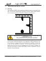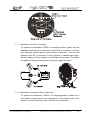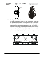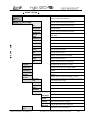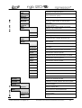
1
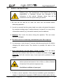
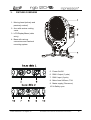
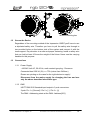
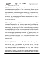
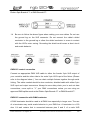
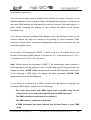
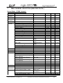
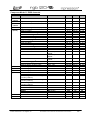
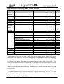
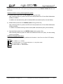
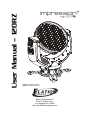
User Manual – 120RZ RGB 120 RZ Software version 1.00/01 (DMX manual version 1.0) Elation Professional™ 6122 S. Eastern Ave. Los Angeles CA. 90040 http://www.ElationLighting.com Elation Professional • Los Angeles, CA. Error! Reference source not found. / Error! Reference source not found.) 2 Table of content 1. General Information……………………..……………………………………………………… 4 a. Introduction……………………………..………………………………………………. 4 b. Unpacking……………………………………..………………………..…...………..… 4 c. Customer Support…………………………………...……………….………………… 4 d. Warranty Registration……………………………………..……………….……..…… 5 2. Safety Instructions………………………………………………………...……........………….6 3. Fixture Overview………………………………………………………………………………... 8 4. Mounting and Installation…………………………………………………….…….……….…. 12 a. Mounting Positions……………………………………………….……………………. 12 b. Securing…………………………………..…………………………………………….. 14 5. Understanding DMX…………………..………………………………………………………... 15 a. DMX Connections…………………...…………………………………………………. 16 b. DMX Terminator………………………………..………………………………………. 17 c. 3-Pin to 5-Pin Conversion……………………………..………………………………. 17 d. Fixture DMX Addressing.……………..……………………..………………………… 17 6. Fixture Menu..………………………………………….……………………………..………… 19 7. DMX Traits…………………………………………………….………………………………… 23 8. Cleaning and Maintenance……………………………………………….…………………… 28 9. Technical Specifications……………………………..…………………...………….………… 29 Elation Professional • Los Angeles, CA. Error! Reference source not found. / Error! Reference source not found.) 3 1. GENERAL INFORMATION INTRODUCTION: Congratulations, you have just purchased one of the most innovative and reliable lighting fixtures on the market today! The Impression 120RZ,™ has been designed to perform reliably for years when the guidelines in this booklet are followed. Please read and understand the instructions in this manual carefully and thoroughly before attempting to operate this unit. These instructions contain important information regarding safety during use and maintenance. UNPACKING: Thank you for purchasing the Impression 120RZ™ by Elation Professional®. Every Impression 120RZ™ has been thoroughly tested and has been shipped in perfect operating condition. Carefully check the shipping carton for damage that may have occurred during shipping. If the carton appears to be damaged, carefully inspect the unit for damage and be sure all accessories necessary to operate the unit have arrived intact. In the event damage has been found or parts are missing, please contact our customer support team for further instructions. Please do not return this unit to your dealer without first contacting customer support at the number listed below. CUSTOMER SUPPORT: Elation Professional® provides a customer support line, to provide set up help and to answer any question should you encounter problems during your set up or initial operation. You may also visit us on the web at www.elationlighting.com for any comments or suggestions. For service related issue please contact Elation Professional®. Service Hours are Monday through Friday 8:00 a.m. to 5:00 p.m. Pacific Standard Time. Voice: (323) 582-3322 Fax: (323) 832-9142 E-mail: [email protected] Forum: www.ElationLighting.com/forum Warning! To prevent or reduce the risk of electrical shock or fire, do not expose this unit to rain or moisture. Elation Professional • Los Angeles, CA. Error! Reference source not found. / Error! Reference source not found.) 4 Caution! There are no user serviceable parts inside this unit. Do not attempt any repairs yourself, doing so will void your manufactures warranty. Please do not discard the shipping carton in the trash. Please recycle whenever possible. WARRANTY REGISTRATION: The Impression 120RZ™ carries a two year (730 days) limited warranty. Please fill out the enclosed warranty card to validate your purchase. All returned service items whether under warranty or not, must be freight pre-paid and accompany a return authorization (R.A.) number. The R.A. number must be clearly written on the outside of the return package. A brief description of the problem as well as the R.A. number must also be written down on a piece of paper and included in the shipping container. If the unit is under warranty, you must provide a copy of your proof of purchase invoice. Items returned without a R.A. number clearly marked on the outside of the package will be refused and returned at customer’s expense. You may obtain a R.A. number by contacting customer support at (323) 582-3322. Never open this fixture while in use! This fixture operates with extremely high voltages. Shock may occur if this fixture is opened during use. All electrical connections must be performed by qualified personal. Elation Professional • Los Angeles, CA. Error! Reference source not found. / Error! Reference source not found.) 5 2. SAFETY INSTRUCTIONS To guarantee a smooth operation, it is necessary to respect the following rules. The manufacturer of this device will not take responsibility of damages through any disregard of the information in this manual. Warranty claims also will be cancelled in case the system casing is opened. 1. Be sure the fan and the air inlets are clean and not blocked before attempting operation. 2. It must be assured that the system-head can rotate unhindered throughout the complete rotating range. A safety distance of at least 0.5 m to any easily inflammable material (e.g. decoration material) must be adhered. 3. Attention! Don’t touch the device during the operation. This can cause injuries or damages. 4. The fixture doesn’t contain any maintainable parts. Don’t open it! 5. It is necessary to wait at least 15 minutes after disconnecting the AC before changing the optical carrier. Pay attention to possibly hot parts of the system. 6. Never look directly into the beam of light or LEDs. Never use optical apertures with a distance less than 0.5 m to observe the beam of light. LED Class 2M. You'll risk a serious injury of your eyes and in particular of your retina. Attention: LED Class 2M can cause injuries of your eyes even without optical instruments in front of them or within a distance of less than 0.5m and short exposure time. Avoid direct radiation of your eyes! 7. To allow a secure operation, follow also the Installation guide described in chapter 0. Operating the Impression 120RZ without suitable safety aids like Elation Professional • Los Angeles, CA. Error! Reference source not found. / Error! Reference source not found.) 6 Safety cables or clamps/hooks can increase the risk of an accident. 8. Qualified or certified Elation staff should perform all repair, maintenance, and installation work. You need to pay attention to the common rules of technology that are not explicit mentioned in this manual. 9. Use only original spare parts. Any structural modification on the system will terminate all warranty claims. 10. Please keep this instruction manual for later reference. 11. Only handle the power cord by the plug. Never pull out the plug by tugging the wire portion of the cord. 12. Please be aware that damages caused by user modifications to the device are not subject to warranty. 13. Be sure to always use an approved “Power Con” connector. Never attempt to modify the power inlet. Be sure the power cord is never crimped or damaged. If the power cord is damaged, replace it immediately with a new one of similar power rating. 14. Always disconnect from main power before performing any type of service or any cleaning procedure. Elation Professional • Los Angeles, CA. Error! Reference source not found. / Error! Reference source not found.) 7 3. FIXTURE OVERVIEW 1. Moving head (actively and passively cooled) 2. Arm with various cooling vents 3. LCD-Display/Menu (data entry) 4. Base with various connectors and Camlock mounting system 5. Power On/Off 6. DMX- Output (3 pole) 7. DMX- Input (3 pole) 8. Micro-fuse 5x20mm, T5A 9. Mains supply (Powercon) 10. 2x Safety eyes Elation Professional • Los Angeles, CA. Error! Reference source not found. / Error! Reference source not found.) 8 1. Head / LED Lens Assembly – The head assembly consist of the main output lenses, and LED cluster module. A high-velocity variable speed fan is mounted in the head to aid in the cooling process. The fan is designed to vary the velocity at different operating temperatures. When the fixture reaches a predetermined internal operating temperature the fan functions at high speeds. The higher speeds provide better cooling associated with higher operating temperatures during long use. When the fixture is operating at a lower temperature the fans operate at low speed. Be sure to keep all vents clean, blocked cooling vents can shorten LED life and reduce the fixtures reliability. 2. Arm / Cooling Fan – A high-velocity variable speed fan is mounted in the head to aid in the cooling process. The fan is designed to vary the velocity at different operating temperatures. When the fixture reaches a predetermined internal operating temperature the fan functions at high speeds. The higher speeds provide better cooling associated with higher operating temperatures during long use. When the fixture is operating at a lower temperature the fans operate at low speed. Be sure to keep all vents clean, blocked cooling vents can shorten LED life and reduce the fixtures reliability. 3. 4-Segment Menu Display – This display details menu functions. a) Mode Select Button – This button is used to access the fixture’s main system menu and on-board programming functions. b) Enter Select Button – This button is used to select and confirm a menu function when working in the fixture’s operating system. c) Down Select Button – This button is used to scroll backwards when navigating through the system menu. d) Up Select Button - This button is used to scroll forward when navigating through the system menu. 4. Base - This fixture uses an integrated Camlock system for various mounting options built in to the base. The Camlock clamp system allows a quick and efficient means to secure the unit. For proper installation see “Mounting and Installation” on page 12. 5. Power Switch – The switch is used to control main power to fixture’s Elation Professional • Los Angeles, CA. Error! Reference source not found. / Error! Reference source not found.) 9 electronics. 6. DMX Output Jack – This 3-Pin XLR jack is used to send an outgoing DMX signal. For best results this jack should be terminated if it is the last fixture in a DMX daisy-chain (see termination on page 19). 7. DMX Input Jack – This 3-Pin XLR jack is used to receive an incoming DMX signal. 8. Electronics Fuse Holder – This housing holds a 250v/4A GMA fuse (120v operation). Never defeat this fuse, this fuse is designed to protect the electronics in the event of severer power fluctuations. In the event of fuse failure, always be sure to replace this fuse with an exact match unless otherwise instructed by an authorized Elation technician. 9. Powercon Connector – This power jack is designed to be used only with the Neutrik Powercon adapter included with your fixture. This jack provides main power to your fixture. 10. Safety Cable Mounting Point Connection – The fixture includes two safety cable slots intergraded into the base. Be sure to use these slots as a secondary rigging point to secure the fixture in the event a clamp fails. Elation Professional • Los Angeles, CA. Error! Reference source not found. / Error! Reference source not found.) 10 4. 1.1 MOUNTING AND INSTALLATION Mounting The Impression 120RZ is fully operational whether it hangs or is mounted to the wall. It can also be operated while standing on the floor. Keep a safety distance of 0.5 m towards any easily inflammable materials (decoration etc.). Pay attention to the regulations of: BGV C1 (former VBG 70) and DIN VDE 0711-217. Only qualified staff shall perform the installation For the various mounting positions of the Impression 120RZ (standing on the floor, sideways or hanging) different accessories kits are available. Through this a safe and firm installation is assured. You'll find special connectors on the bottom side of the fixture that are designed for the floor bracket. In addition the front side of the system is marked with (FRONT) as this is important for an even orientation during installation. Elation Professional • Los Angeles, CA. Error! Reference source not found. / Error! Reference source not found.) 11 1.1.1 Mounting on the Floor (Upright) To operate the Impression 120RZ in an upright position, please use the dedicated tripod which is mounted to the bottom of the fixture. It is fixed with fasteners called Camlock quick-release connectors. Turn the two fasteners both 90° to lock them. Do the opposite to release them again. On both sides you'll find eyelets to pull though a fixing strap. This allows an additional bracing of the system during the upright operation. 1.1.2 Mounting in hanging Position (Head first) To operate the Impression 120RZ in an hanging position, please use a half-coupler (clamp) which is mounted directly to the bottom side of the system. It is fixed centrically with a M10x16 mm thread bolt. Elation Professional • Los Angeles, CA. Error! Reference source not found. / Error! Reference source not found.) 12 1.1.3 Mounting in sidewise Position To operate the Impression 120RZ in a side mount position, please use the optional truss-mounting bar. The truss-mounting bar is attached by two Camlock quick-release connectors. Two half-couplers (clamps) are now used to mount the system to a standard truss bar. This technique is necessary to cope with the excessive torque levels that fixture produces in side mount position. Failure to use the truss-mount bar can result in severe damage to the fixture. In addition it allows a concentrically position between two truss belts. Never use the clamp mounting procedure detailed in the illustration above for side mounting. Elation Professional • Los Angeles, CA. Error! Reference source not found. / Error! Reference source not found.) 13 Without mounting bar 1.2 Secure the Device Regardless of the mounting method of the Impression 120RZ you'll have to use a stipulated safety wire. Therefore you have to pull the safety wire through to two provided holes on the bottom side of the system and connect it with the truss-support. Pay attention to a safe and proper fastening. Install a safety wire that can hold at least 10 times the weight of the fixture. Never use the carrying handles for this purpose. 1.3 Connections 1.3.1 Power Supply ~100-240 Volt AC, 50-60 Hz, earth contact type plug - Powercon Connected load 350 VA (W) <=> T5A (micro-fuse 5x20mm) Please see printing on the case for the right electronic supply! Disconnect from the mains supply for changing the fuse and use only the above described micro-fuse type. 1.3.2 DMX USITT DMX-512 Standard input/output in 3 pole connectors. 3 pole: Pin 1 = [Ground] / Pin 2 = [-] / Pin 3 = [+] The DMX- Addressing starts at the DMX- Address [001]. Elation Professional • Los Angeles, CA. Error! Reference source not found. / Error! Reference source not found.) 14 5. UNDERSTANDING DMX DMX-512: DMX is short for Digital Multiplex. This is a universal protocol used by lighting and controller manufactures as a form of communication between intelligent fixtures and controllers. DMX allows all makes and models of different manufactures to be linked together and operate from a single controller. This is possible as long as all the fixtures and the controller are DMX compliant. A DMX controller sends the DMX data instructions to a fixture allowing the user to control the different aspects of an intelligent light. DMX data is sent out as serial data that travels from fixture to fixture via data “IN” and “OUT” XLR terminals located on the fixtures (most controllers will only have output jacks). DMX Linking: To ensure proper DMX data transmission, always use proper DMX cables and a terminator, never use microphone cables. When using several DMX fixtures try to use the shortest cable path possible. Never split a DMX line with a “Y” style connector. The order in which the fixtures are connected in a DMX line does not influence the DMX addressing. For example; a fixture assigned a DMX address of 1 may be placed anywhere in the DMX chain, at the beginning, at the end, or anywhere in the middle. The DMX controller knows to send data assigned to address 1 to that fixture no matter where it is located in the DMX chain. The Impression 120RZ™ can be controlled via DMX-512 protocol. The Impression 120RZ™ is a fixture that can operate in three different DMX modes; 11, 14, or 15 channels (see page 20 for the different DMX operations). The DMX address is set electronically using the controls on the LED menu. Data Cable (DMX Cable) Requirements (For DMX and Master/Slave Operation): Your fixture and your DMX controller require a standard 3-pin XLR connector for data input and data output. If you are making your own cables, be sure to use two conductor shielded digital DMX cable rated at 120 ohms, this cable is designed for DMX transmission and may be purchased from your Elation dealer or at most professional lighting retailers. Your cables should be made with a male and female XLR connector on either end of the cable. Also, remember that a DMX line must be daisy chained and cannot be split, unless using an approved DMX splitter such as the Elation Professional • Los Angeles, CA. Error! Reference source not found. / Error! Reference source not found.) 15 Elation Opto Branch 4™ or DMX Branch/4™. 1.4 Be sure to follow the above figure when making your own cables. Do not use the ground lug on the XLR connector. Do not connect the cable’s shield conductor to the ground lug or allow the shield conductor to come in contact with the XLR’s outer casing. Grounding the shield could cause a short circuit and erratic behavior. DMX-512 control connection Connect an appropriate DMX XLR cable to either the female 3-pin XLR output of your controller and the other side to the male 3-pin XLR input of the fixture (Please refer to the diagram below.). You can chain multiple fixtures together through serial linking. The cable needed should be two conductor, shielded cable with either 3-pin XLR input and output connectors. Always be sure daisy chain your in and out data connections, never split or “Y” your DMX connections unless you are using an approved DMX splitter such as the Elation Opto Branch 4™ or DMX Branch/4™. DMX-512 connection with DMX terminator A DMX terminator should be used in all DMX lines especially in longer runs. The use of a terminator may avoid erratic behavior in your DMX line. A terminator is a 120 ohm 1/4 watt resistor that is connected between pins 2 and 3 of a male XLR Elation Professional • Los Angeles, CA. Error! Reference source not found. / Error! Reference source not found.) 16 connector (DATA + and DATA -). This fixture is inserted in the female XLR connector of the last fixture in your daisy chain to terminate the line. Using a line terminator (Elation part: DMX T PACK) will decrease the possibilities of erratic behavior. 5-Pin XLR DMX Connectors. Some manufactures use 5-pin XLR connectors for DATA transmission in place of 3-pin. 5-pin XLR fixtures may be implemented in a 3pin XLR DMX line. When inserting standard 5-pin XLR connectors in to a 3-pin line a cable adaptor must be used, these adaptors are readily available at most electric stores. The following chart details a proper cable conversion. Fixture DMX addressing; All fixtures should be given a DMX starting address when using a DMX controller, so the correct fixture responds to the correct control signal. This digital starting address is the channel number from which the fixture starts to “listen” to the digital control information sent out from the DMX controller. The allocation of this starting DMX address is achieved by setting the correct DMX address on the digital display located Elation Professional • Los Angeles, CA. Error! Reference source not found. / Error! Reference source not found.) 17 on the back of the fixture. You can set the same starting address for all fixtures or a group of fixtures, or set different address for each individual fixture. Be advised that setting all you fixtures to the same DMX address will subsequently control all fixtures in the same fashion, in other words, changing the settings of one channel will affect all the fixtures simultaneously. If you set each fixture to a different DMX address, each unit will start to “listen” to the channel number you have set, based on the quantity of control channels (DMX channels) of each fixture. That means changing the settings of one channel will only affect the selected fixture. In the case of the Impression 120RZ ™, which is up to a 15 channel fixture, you should set the starting DMX address of the first unit to 1, the second unit to 16 (15 + 1), the third unit to 31 (15 + 16), and so on. Note: During start-up the Impression 120RZ ™ will automatically detect whether a DMX data signal is being received or not. If a DMX data signal is being received, the display will show "A.XXX" (XXX representing the actual DMX address). If the fixture is not receiving a DMX signal the display will flash repeatedly "A.XXX" (XXX representing the actual DMX address). If your fixture is connected to a DMX controller and the display is flashing (not receiving a DMX signal), please check the following: - The 3-pin plug (cable with DMX signal from controller) may not be connected or is not inserted completely into the DMX input jack. - The DMX controller is switched off or defective. - The DMX cable or connector is defective. - A DMX terminator has been inserted into the last fixture in your DMX chain. Elation Professional • Los Angeles, CA. Error! Reference source not found. / Error! Reference source not found.) 18 6. FIXTURE MENU On-Board System Menu: The Impression 120RZ™ comes with an easy to navigate system menu. This next section will detail the functions of each command in the system menu. LCD Control Panel: The control panel located on the arm of the fixture allows you to access the main menu and make all necessary adjustments to the Impression™. During normal operation, tapping the “MODE” key once will access the fixture’s main menu. Once in the main menu you can navigate through the different functions and access the sub-menus with the Up and Down buttons. Once you reach a field that requires adjusting, tap the ENTER button to activate that field and use the UP and Down button to adjust the field. Tapping the Enter button once more will confirm your setting. Once a setting is saved the LED will briefly readout PASS to confirm a new setting has been made and locked into memory. You may exit the main menu at any time without making any adjustments by tapping the MODE button. MODE Button - To access the main menu locate the MODE button on the front of the unit. Press this button to activate the system menu. Tap the UP button until you reach the function you wish to change. When you reach the function you wish to change tap the ENTER button once to select that menu function. When a function is selected the menu will begin to flash, use the UP or DOWN button to change the function. Once your changes are made tap the ENTER button yet again to lock the change in the system menu. To exit without making any changes tap the MODE button. The Menu Field You’ll find the control board on the side part of the arm. It allows you to make all necessary adjustments of the Impression 120RZ. With the Mode-key you get into the main menu. Afterwards you can navigate through the menu with the Up/Down-keys. Push the Enter-key to get in the next menu level or to confirm your settings. Make them and set functions ON/OFF with the Up/Down-keys. Confirm and save it with the Enter-key (the display shows OK). Push the Mode-key to cancel the entry and go back to the main menu. Elation Professional • Los Angeles, CA. Error! Reference source not found. / Error! Reference source not found.) 19 MODE - ENTER Level1 DMX Start Address 001 Level 2 Special Manual DMX Level 3 Level 4 Remark DOWN - UP Define the DMX start address Manual control of all system functions Pan Manual control for Pan (X-movement) Speed Movements Pan/Tilt Movements Speed adjustment for Pan/Tilt movements see also item below Manual control for Pan/Tilt movement Special Activate the White- or Full-Power Mode; see also DMX table White Temperature Manual control for Color temperature Dimmer Manual control for Dimmer Shutter Manual control for Shutter Blue Manual control for blue Green Manual control for green Red Manual control for red Color Wheel Manual control for the color wheel Zoom Manual control for zoom Tilt Manual control for Tilt (Y-movement) Display Contrast Adjustment for the Display contrast Default Set Resetting all functions to original values Set Dimmer Frequency LED Dimmer Version Impression Version Changes PMW frequency between 600Hz and 1200Hz Reads out the current LED dimmer (software) version Adjust Reads out the current CPU software version Key code xxxx Use the code for entering the calibration menu (for authorized persons only) Pan Offset Calibration for Pan-Offset Tilt Offset Calibration for Tilt-Offset Clear EEPROM Erase EEPROM memory Diagnose Diagnose functions Pos Feed Pan Delta Anz Ti0Int-Err PFC Voltage Pos Feed Tilt Delta Temperature Arm Elation Professional • Los Angeles, CA. Internal data and function diagnose Internal data and function diagnose Show the present PFC voltage Internal data and function diagnose Indicates the arm temperature Error! Reference source not found. / Error! Reference source not found.) 20 DOWN - UP Temperature Head PAN/TILT Motor Power PAN/TILT Silent Mode Indicates the head temperature Switches power for Pan/Tilt ON or OFF (disconnected from power) Reduces maximum speed for Pan/Tilt Defines whether the last DMX signal is stored or the lamp is switched OFF in case of signal interruption Automatically position feedback (correction) for Pan/Tilt movement Adjustments for a uniform white color (white balance); only in white-mode DMX Hold Position Feedback White Adjust Red Input for red adjustments Blue Input for blue adjustments Green Input for green adjustments Set DMX Image DMX input Monitor Stores the Scene currently sent to the unit Indicates the presently received DMX signal per DMX channel Pan Instantaneous value for Pan Speed Movements Pan/Tilt Movements Speed adjustment for Pan/Tilt movements see item below Special Instantaneous value for Special White Temperature Adjustment of the color temperature for WHITE Dimmer Instantaneous value for Dimmer Shutter Instantaneous value for Shutter Blue Instantaneous value for Blue Green Instantaneous value for Green Red Instantaneous value for Red Zoom Instantaneous value for Zoom Color Wheel Instantaneous value for Color Mixing unit Tilt Instantaneous value for Tilt movement Instantaneous value for Pan/Tilt movements Performs an automatic self-test Live time Indicates the overall operation time of the system Display Adjust the display DOWN - UP Self test Blackout Select DMX Mode ON/OFF: Display OFF Please select the desired DMX Mode Compressed Normal Elation Professional • Los Angeles, CA. Fixture works in "Compressed" mode see also section 0 below Fixture works in "Normal" mode see also section 0 below Error! Reference source not found. / Error! Reference source not found.) 21 HighResolution White Mode Fixture works in "High Resolution" mode see also section 0 below ON/OFF: Adjustments for white-balance are activated Reverse Pan ON/OFF: Invert Pan movements Reverse Tilt ON/OFF: Invert Tilt movements Reset RESET and new calibration for all functions Elation Professional • Los Angeles, CA. Error! Reference source not found. / Error! Reference source not found.) 22 7. DMX CHANNEL SELECTION (DMX PROTOCOL) Normal-Mode 15 DMX channels Channel Function Time and Value DMX HEX % 1) PANcoarse 2) PAN-fine 3) Tiltcoarse 4) Tilt-fine 5) Color (fixed) 0 .. 660° 3,2 s 0..255 00..FF 0..100 High- Pos ... High- Pos + 2,6° (16 Bit) 0 .. 300° 1,5 s 0..255 0..255 00..FF 00..FF 0..100 0..100 0..255 0..7 8..15 16..23 24..31 32..39 40..47 48..55 56..63 64..71 72..79 80..87 88..95 96..103 104..111 00..FF 00..07 08..0F 10..17 18..1F 20..27 28..2F 30..37 38..3F 40..47 48..4F 50..57 58..5F 60..67 68..6F 0..100 0..2,5 3..5,5 6..8,5 9..12,5 13..15,5 16..18,5 19..21,5 22..24,5 25..27,5 28..30,5 31..34,5 35..37,5 38..40,5 41..43,5 112..119 70..77 44..46,5 120..127 78..7F 47..49,5 slow - fast slow - fast 128 129..223 224.255 0..255 0..255 0..255 0..15 16..47 48..79 80 81..DF E=..FF 00..FF 00..FF 00..FF 00..0F 10..2F 30..4F 50 51..88 89..100 0..100 0..100 0..100 0..5,5 6..18,5 19..31 slow - fast 80..111 50..6F 32..43 slow - fast 112..143 70..8F 44..56 5s .. 1s 1 Hz .. 10 Hz 144..199 200..239 240..255 0..255 0..6 7..255 A0..C7 C8..EF F0..FF 0..FF 0..06 07..FF 57..77 78..94 95..100 0..100 0..2 3..100 0..15 0..0F 0..5,5 16..31 224..229 10..1F E0..E5 6..12,5 88..89,5 High- Pos … High- Pos + 1,2° (16 Bit) Colors adjustable via RGB 1) Color 01 - Red 1) Color 02 - Amber 1) Color 03 - Warm Yellow 1) Color 04 - Yellow 1) Color 05 - Green 1) Color 06 - Turquoise 1) Color 07 - Cyan 1) Color 08 - Blue 1) Color 09 - Lavender 1) Color 10 - Mauve 1) Color 11 - Magenta 1) Color 12 - Pink White - CTO White White - CTB 2) Rainbow Effect Stop 3) Rainbow Effect Rainbow Effect, random colors 6) Red Color mixing system - Red 7) Green Color mixing system - Green 8) Blue Color mixing system - Blue 9) Shutter Shutter closed Random Pulse effect Up-dimming then Shutter closing (random patterns) Shutter open then down-dimming (random patterns) Up-dimming then down-dimming (random patterns) Strobe effect pause Strobe effect, slow - fast Shutter open 10) Dimmer Dimmer 11) Color No color temperature correction temperature Continuous color temperature correction between 3200k - 7200k 4) 12) Special Max. Power-Mode 4) White-Mode Fan min. as long as temp. < 90°C Elation Professional • Los Angeles, CA. Color temperature 3200K Color temperature 5600K Color temperature 7200K slow - fast slow - fast 0 - 100% 0 - 100% 0 - 100% 0 - 100% Applicable only for 5) White color Max. light output without white balance White balance used Error! Reference source not found. / Error! Reference source not found.) 23 Channel 13) Movement 14) Speed Pan/Tilt 15) Zoom 4) Function Time and Value RESET (Normal Mode) No movement Movement Size Phase PAN 1 0° 1 90° 1 180° 1 270° PAN 2 0° 2 90° 2 180° 2 270° PAN 3 0° 3 90° 3 180° 3 270° PAN 4 0° 4 90° 4 180° 4 270° TILT size / phase see also PAN PAN / TILT size / phase see also PAN PAN / TILT (inverse) size / phase see also PAN Circle size / phase see also PAN Circle (inverse) size / phase see also PAN Lying eight size / phase see also PAN Random movement size see also PAN Pan/Tilt relative movement Pan/Tilt slow – fast Pan Min. 660° = 200s Use this channel 14) also for the speed Pan Max. 660° = 3,2s of the movements (channel 13). Tilt Min. 300° = 110s Tilt Max. 300° = 1,5s Spot - Flood 10° - 26° DMX HEX % 250..255 0 FA..FF 00 98..100 0 01..01 02..03 04..05 06..07 08..09 10..11 12..13 14..15 16..17 18..19 20..21 22..23 24..25 26..27 28..29 30..31 32..63 64..95 96..127 128..159 160..191 192..223 224..255 0..15 16..255 01..01 02..03 04..05 06..07 08..09 0A..0B 0C..0D 0E..0F 11..11 12..13 14..15 16..17 18..19 1A..1B 1C..1D 1E..1F 20..3F 40..5F 60..7F 80..9F A0..BF C0..DF E0..FF 00..0F 10..FF 0,5 1,0 1,7 2,5 3,3 4,1 4,9 5,7 6,5 7,3 8,0 8,8 9,6 10,4 11,2 12 13..25 26..37 38..50 51..62 63..75 76..87 88..100 0..6 7..100 0…255 00…FF 0…100 Max. Power-Mode vs. White-Mode The Impression 120RZ can regard the white-balance adjustments for each individual color setting. Whether the White-Mode is used with RGB can be selected in the Normal DMX-Mode during operation with the Special DMX channel. If the Special channel is set to a value between DMX 0..15, the White-Mode is not used and the RGB goes for the maximum light output. If the Special channel is set to a value between DMX 16..31, the white balance is used for the RGB output. Since there is no Special DMX channel in the Compress DMX-Mode, the possibility exists to likewise select these settings also in the display menu. If the White-Mode is set to “ON”, the white-balance is activated. If the White-Mode is set to “OFF”, the RGB goes for the maximum light output (Max. PowerMode). 5) The continuous color temperature correction is applicable only for the White color i.e. if this function is selected (DMX ≥ 006) the Impression 120RZ will change the color to white immediately and will then be adjustable in the color temperature in a range between 3200K and 7200K. Hence a color correction for others than white is not intended. Elation Professional • Los Angeles, CA. Error! Reference source not found. / Error! Reference source not found.) 24 Compress-Mode 11 DMX channels Channel Function 1) PAN0 .. 660° coarse 2) PAN-fine High- Pos ... High- Pos + 2,6° (16 Bit) 3) Tilt0 .. 300° coarse 4) Tilt-fine High- Pos … High- Pos + 1,2° (16 Bit) 5) Color Colors adjustable via RGB 1) (fixed) Color 01 - Red 1) Color 02 - Amber 1) Color 03 - Warm Yellow 1) Color 04 - Yellow 1) Color 05 - Green 1) Color 06 - Turquoise 1) Color 07 - Cyan 1) Color 08 - Blue 1) Color 09 - Lavender 1) Color 10 - Mauve 1) Color 11 - Magenta 1) Color 12 - Pink White - CTO White White - CTB 2) Rainbow Effect Stop 3) Rainbow Effect Rainbow Effect, random colors 6) Red Color mixing system - Red 7) Green Color mixing system - Green 8) Blue Color mixing system - Blue 9) Shutter Shutter closed Random Pulse effect Up-dimming then Shutter closing (random patterns) Shutter open then down-dimming (random patterns) Up-dimming then down-dimming (random patterns) Strobe effect pause Strobe effect, slow - fast Shutter open RESET Shutter open 10) Dimmer Dimmer 11) Zoom Spot - Flood Elation Professional • Los Angeles, CA. Time and Value DMX HEX % 3,2 s 0..255 00..FF 0..100 1,5 s 0..255 0..255 00..FF 00..FF 0..100 0..100 0..255 0..7 8..15 16..23 24..31 32..39 40..47 48..55 56..63 64..71 72..79 80..87 88..95 96..103 104..111 00..FF 00..07 08..0F 10..17 18..1F 20..27 28..2F 30..37 38..3F 40..47 48..4F 50..57 58..5F 60..67 68..6F 0..100 0..2,5 3..5,5 6..8,5 9..12,5 13..15,5 16..18,5 19..21,5 22..24,5 25..27,5 28..30,5 31..34,5 35..37,5 38..40,5 41..43,5 112..119 70..77 44..46,5 120..127 78..7F 47..49,5 slow - fast slow - fast 128 129..223 224.255 0..255 0..255 0..255 0..15 16..47 48..79 80 81..DF E0..FF 00..FF 00..FF 00..FF 00..0F 10..2F 30..4F 50 51..88 89..100 0..100 0..100 0..100 0..5,5 6..18,5 19..31,5 slow - fast 80..111 50..6F 32..43 slow - fast 112..143 70..8F 44..56 5s .. 1s 1 Hz .. 10 Hz 144..199 200..239 240...249 250 251..255 0..255 0…255 A0..C7 57..77 C8..EF 78..94 F0..F9 95..97,5 FA 98 FB..FF 99..100 0..FF 0..100 00…FF 0…100 Color temperature 3200K Color temperature 5600K Color temperature 7200K slow - fast slow - fast 0 - 100% 0 - 100% 0 - 100% Min. 3 Sec. 0 - 100% 10° - 26° Error! Reference source not found. / Error! Reference source not found.) 25 High Resolution (Extended) -Mode 14 DMX Channels Channel Function Time and Value DMX HEX % 1) PANcoarse 2) PAN-fine 3) Tiltcoarse 4) Tilt-fine 5) Redcoarse 6) Red-fine 7) Greencoarse 8) Greenfine 9) Bluecoarse 10) Blue-fine 11) Shutter 0 .. 660° 3,2 s 0..255 00..FF 0..100 High- Pos ... High- Pos + 2,6° (16 Bit) 0 .. 300° 1,5 s 0..255 0..255 00..FF 00..FF 0..100 0..100 High- Pos … High- Pos + 1,2° (16 Bit) Color mixing system – Red 0 - 100% 0..255 0..255 00..FF 00..FF 0..100 0..100 Color mixing system – Red-Low Color mixing system – Green 0 - 100% 0..255 0..255 00..FF 00..FF 0..100 0..100 0..255 00..FF 0..100 0 - 100% 0..255 00..FF 0..100 slow - fast slow - fast 0..255 0..15 16..47 48..79 00..FF 00..0F 10..2F 30..4F 0..100 0..5,5 6..18,5 19..31,5 slow - fast 80..111 50..6F 32..43 slow - fast 112..143 70..8F 44..56 5s to 1s 1 Hz .. 10 Hz 144..199 A0..C7 57..77 200..239 C8..EF 78..94 240...249 F0..F9 95..97,5 250 FA 98 251..255 FB..FF 99..100 0..255 0..FF 0..100 Color mixing system – Green-Low Color mixing system – Blue Color mixing system – Blue-Low Shutter closed Random Pulse effect Up-dimming then Shutter closing (random patterns) Shutter open then down-dimming (random patterns) Up-dimming then down-dimming (random patterns) Strobe effect pause Strobe effect, slow - fast Shutter open RESET Shutter open 12) Dimmer- Dimmer coarse 13) Dimmer- Dimmer - Low fine 14) Zoom Spot - Flood 1) Min. 3 Sec. 0 - 100% 10° - 26° 0..255 0..FF 0..100 0…255 00…FF 0…100 The predefined colors can be used as start-colors for the Rainbow effect. Please select first a Impression 120RZ will afterwards start from that color and will execute the rainbow effect synchronously. Different Impression 120RZ desired start-color before you activate the rainbow effect. All can certainly have different start-colors but will still execute the rainbow effect synchronously. If you choose a color different from the once marked with 1) in the tables above the rainbow start-color will be red. 2) Rainbow-effect Stop will pause this function. After resuming the rainbow-effect will be continued with the current color. 3) The Rainbow-effect will run synchronously only if it will be started going out from one of the predefined colors (see also 1) before). Locking and unlocking the Control Panel Elation Professional • Los Angeles, CA. Error! Reference source not found. / Error! Reference source not found.) 26 Please lock and unlock the control panel by pressing the menu keys MODE & ENTER & UP at the same time. Additional features during switching-ON the system a) 1200Hz Mode (Hold down the UP- button during power ON) After switching ON the system the LEDs will be operated with a Pulse Width Modulation (PWM) of 1200Hz. In addition all standard setting will be loaded (DMX start address [001], Normal Mode). b) 600Hz Mode (Hold down the DOWN- button during power ON) After switching ON the system the LEDs will be operated with a Pulse Width Modulation (PWM) of 600Hz. In addition all standard setting will be loaded (DMX start address [001], Normal Mode). c) Standard Mode (Hold down the ENTER- button during power ON) After switching ON the system the DMX start address will be set to [001]. All other setting remain unchanged. Additional Display Indications As a default you'll find the following additional information in the first row of the LCD display: XX/X/XX 06 = 600Hz / 12 = 1200Hz N = Normal Mode / C = Compressed Mode / H = High Res. Mode N = Tilt normal / I = Tilt inverted N = Pan normal / I = Pan inverted Elation Professional • Los Angeles, CA. Error! Reference source not found. / Error! Reference source not found.) 27 8. MAINTAINING AND CLEANING THE IMPRESSION 120RZ The Impression 120RZ is a system of very low maintenance. It is only necessary to clean the air in- and outlets as well as the optical LED lenses from time to time. For a safe operation it is absolutely essential that the fixture is kept clean and that dust, dirt and smoke-fluid residues must not built up on or within the fixture. Otherwise the fixture's light-output will be significantly reduced or damages can occur. Regular cleaning will not only ensure the maximum light-output, but will also allow the fixture to operate reliably throughout its life. A soft lint-free cloth moistened with any good glass cleaning fluid is recommended, under no circumstances should alcohol or solvents be used! 1.5 1.6 Safety regulations • Pull out the main plug! • Wait min. 15 minutes after the last operation to cool down the fixture. Circumference and Interval (rule-of-thumb) The contamination of the fixture depends on the environment details. Hence no general guidelines can be given. The intervals given below are only suggestions from our practice experience. Position Interval In this way LED reflector and optical system Weekly Soft brush /lint-free cloth Fan and air channel Monthly Vacuum cleaner, airbrush, etc. Attention: • Never let optical parts come into contact with oil or fat. • Before running the fixture wait until all parts are dried up. • Never tough lenses with bare fingers. Elation Professional • Los Angeles, CA. Error! Reference source not found. / Error! Reference source not found.) 28 9. TECHNICAL SPECIFICATIONS Power supply Power consumption 350 VA (Watt) Power Input 100~240 V AC, 50-60 Hz (wide range input) Fuse protection Micro-fuse 5x20 mm, T5A Operational Parameters Max. Ambient 45°C (integrated overheating switch) Temperature Mounting Position Any (see chapter mounting) Lighting System - Additive Color mixing LED Type 120x Rebel High-power- LEDs Lifetime 100.000 h 42x green LEDs, 36x blue LEDs, 42x red LEDs Wavelength optimized for maximum presentable color space Optical System High efficient Collimator cluster Fixed optical mount with an angel of reflected beam between 10° - 26° Shutter / Dimmer (8/16 Bit) Strobe- Effect with variable speed between 1 - 10 flashes per second, Random-Strobe, PulseEffects Continuous Dimmer 0 - 100% DMX Control Standard USITT DMX-512, 3 pole XLR; [+] = Pin 3 [-] = Pin 2 [Ground] = Pin 1. Die DMX- Addressing starts at the DMX channel [001]. Pan / Tilt (8/16 Bit) Pan- movement Tilt- movement Weights and Measures Width of the base Length of the base height (head vertical) Weight (net) 660° in min. 3,2 seconds (Position Feedback) 300° in min. 1,5 seconds (Position Feedback) 340 mm 145 mm 370 mm 8.0 kg Elation Professional • Los Angeles, CA. Error! Reference source not found. / Error! Reference source not found.) 29 Index A Angel of reflected beam ............................ 20 B BGV C1 ........................................................... 7 C Camlock .......................................................... 8 Circumference............................................... 18 Cleaning ........................................................ 18 Compress-Mode .................................... 15, 16 D Danger of BURNING ..................................... 6 Description of Device ...................................... 5 DIN VDE 0711-217 ......................................... 7 DMX .............................................................. 10 Mounting in hanging Position.......................... 8 Mounting in sidewise Position......................... 9 Mounting on the Floor ..................................... 8 N Normal-Mode ............................................... 13 O Optical parts ................................................ 19 P Pan- Movement............................................. 20 Power Supply .............................................. 10 Powercon ........................................................ 5 R Rebel High-power- LEDs .......................... 20 S E e-mail .............................................................. 1 Enter-key .................................................... 11 Eyelets ............................................................ 8 Safety distance ............................................... 7 Safety Instructions .......................................... 6 Secure the Device ....................................... 10 Software Version............................................. 1 H T Half-couplers (clamps) .................................... 9 I Instruction Version .......................................... 1 Internet ............................................................ 2 L LED Class 2M ................................................ 6 M Maintenance ................................................. 18 Max. Power-Mode........................................ 15 Menu Field .................................................... 11 Micro-fuse ..................................................... 10 Mode-key .................................................... 11 Mounting ........................................................ 7 Elation Professional • Los Angeles, CA. Technical Specifications ............................ 20 Tilt- Movement .............................................. 20 U Up/Down-keys ........................................... 11 V VBG 70 ........................................................... 7 W Warranty claims .............................................. 6 Weights and Measures ................................. 20 White-Mode.................................................. 15 Error! Reference source not found. / Error! Reference source not found.) 30 NOTES: Elation Professional • Los Angeles, CA. Error! Reference source not found. / Error! Reference source not found.) 31 Elation Professional 6122 S. Eastern Ave. Los Angeles, Ca. 90040 323-582-3322 Voice / 323-832-9142 Fax www.ElationLighting.com