1
Multicast Video Distribution System
MVDS X-1
Installation / User's Guide
Introduction
Thank you very much for purchasing Silex's MVDS X-1, the Multicast Video
Distribution System (this product).
This manual provides how to setup and use this product.
About notation
- Copying all or a part of this manual without our permission is prohibited.
- The contents of this manual may be changed without advance notice.
- Please note that the actual screens may vary from the examples in this manual.
This can be caused by different versions of operating systems on the PC,
upgrades, etc.
- This manual has been edited very carefully. However, Silex Technology, Inc. is
not responsible for any mistakes included in this manual or any damages, direct
or indirect, arising from the use of this manual.
- Information and descriptions contained herein are the property of Silex
Technology, Inc. Such information and descriptions may not be copied,
disseminated, or distributed without the express written consent of Silex
Technology, Inc. This publication is subject to change without notice.
About trademarks
- Microsoft and Windows are either registered trademarks or trademarks of
Microsoft Corporation in the United States and/or other countries.
- Ethernet is a registered trademark of Xerox Corporation.
- Other brand or product names are registered trademarks or trademarks of their
respective owners.
©Copyright 2008 Silex Technology, Inc.
Index
Product Overview..................................................... 1
1.1 About this product ........................................................................................2
1.2 Speci�cation.....................................................................................................4
1.2.1 Hardware speci�cation.....................................................................................................................4
1.2.2 Software speci�cation ......................................................................................................................6
1.2.3 Interface speci�cation ......................................................................................................................7
1.2.4 Notes on the radio wave..................................................................................................................8
1.3 Network composition ..................................................................................9
1.4 Parts and function....................................................................................... 12
Installation .............................................................. 15
2.1 Before you begin ......................................................................................... 16
2.1.1 Necessary items ............................................................................................................................... 16
2.1.2 Create environment for setup .................................................................................................... 17
2.2 Con�gure this product .............................................................................. 19
2.2.1 Assign IP address ............................................................................................................................. 19
2.2.2 Con�gure via Web browser.......................................................................................................... 21
Host name / Password con�guration............................................................................................. 22
Network con�guration ........................................................................................................................ 23
Adjusting a screen image (at transmitter) .................................................................................... 25
Adjusting a screen image (at receiver(s))...................................................................................... 27
2.3 Hardware installation................................................................................. 28
2.3.1 Connect to a wired network........................................................................................................ 28
2.3.2 Connect to a wireless network ................................................................................................... 29
Vertical convergence angle and minimum distance ................................................................ 30
Vertical coverage and Line-of-sight................................................................................................ 31
Monitor and Maintenance ..................................... 33
3.1 Front panel..................................................................................................... 34
3.1.1 Menu structure and how to use it ............................................................................................. 34
3.1.2 Functions available in each menu............................................................................................. 36
Initial screen (Level:0)........................................................................................................................... 36
SERVICE ACTIVITY.................................................................................................................................. 37
CONNECTION STAT................................................................................................................................ 38
DEVICE INFO ............................................................................................................................................ 39
ADMIN MODE MENU............................................................................................................................ 40
3.2 Web interface................................................................................................ 46
3.2.1 Status ................................................................................................................................................... 48
General ...................................................................................................................................................... 48
Network .................................................................................................................................................... 49
Video/Audio/Data ................................................................................................................................. 50
3.2.2 Con�guration.................................................................................................................................... 51
General ...................................................................................................................................................... 51
Network .................................................................................................................................................... 52
Video/Audio/Data (at transmitter) .................................................................................................. 54
Video/Audio/Data (at receiver)......................................................................................................... 57
Static Node (at transmitter) ............................................................................................................... 59
Static Node (at receiver)...................................................................................................................... 60
Dynamic Node (at transmitter)......................................................................................................... 61
Dynamic Node (at receiver) ............................................................................................................... 62
3.2.3 Tools ..................................................................................................................................................... 63
Common................................................................................................................................................... 63
Video/Audio (at transmitter) ............................................................................................................. 64
Video/Audio (at receiver).................................................................................................................... 65
Appendix................................................................A-1
A-1 Con�guration item list............................................................................ A-2
1.Product Overview
1
Product Overview
1
MVDS X-1 User's Guide
1.1 About this product
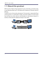
MVDS stands for "Multicast Video Distribution System", which allows to distribute video
or audio data from Player (e.g. PC, DVD player, etc) to Display (e.g. TV, Monitor, etc) by IP
Multicast.
The MVDS consists of transmitter and receiver(s). The transmitter is connected to Player
and the receiver(s) are connected to Display. Transmitter encodes the signal output
from the Player (e.g. video, audio, etc.) and distributes its codec data to receiver(s) in
real time, and the receiver(s) decodes and outputs it on Display.
Decode D/A
A/D Encode
IP Network
X-1T
X-1R
Serial
Audio
Video
2
1.Product Overview
Feature
Video and Audio control
-
Adopts JPEG2000 codec. High compression with less image degradation available
Audio codec: 16bit stereo PCM (Sampling rate: 32KHz)
Screen size supports WXGA (1280x768)
Up to 30fps of frame rate
Synchronization function for video and audio (Lip-sync)
Network control
- Allow simultaneous distribution to multiple receivers by multicast (up to 32 receivers)
- Time correction between transmitter and receivers allows simultaneous
output among receivers
- Support Wired LAN(10Base-T/100Base-TX) and Wireless LAN (IEEE802.11a/g:
Infrastructure/ad hoc mode)
Others
- Support 1ch of serial port for remote monitoring and control
- Various con�gurations are available on embedded Web page
- Switch the transmitter automatically at a speci�ed interval
- Connection and communication status can be veri�ed at LCD (Transmitter only)
3
MVDS X-1 User's Guide
1.2 Speci�cation
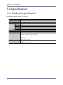
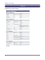
1.2.1 Hardware speci�cation
Hardware speci�cation is as follows:
CPU
RAM
ROM
Interface
Power
LCD
LED
Push Switch
4
Video
Audio
Serial
Ethernet
Wireless
TOSHIBA TX4939 400MHz (32/64bit MIPS)
128MB DDR
8MB
Analog RGB D-SUB15 x 1
16bit Stereo line in / out (Mini Jack)
RS-232C (D-SUB9) x 1
10BASE-T/100BASE-TX Auto detection (RJ-45) x 1
IEEE802.11a/b/g mini PCI module x 1 (SX-10WAG)
AC adapter (Operating voltage 15V)
16 Characters x 2 Lines (Transmitter only)
4 Front Side
"Power" / "Status" / "Wireless" / "Ether"
2 Back Side
RJ-45 "Link" / "Status"
4 Front Side
"MEMU" / "-" / "+" / "SET"
1.Product Overview
FCC Notices
This equipment has been tested and found to comply with the limits for a Class
A digital device, pursuant to Part 15 of FCC Rules. These limits are designed to
provide reasonable protection against harmful interface when the equipment
is operated in a commercial environment. This equipment generates, uses, and
can radiate radio frequency energy and, if not installed and used in accordance
with the instruction manual, may cause harmaful interference to radio
communications. Operation of this equipment in a residential area is likely to
cause harmful interference in which case the user will be required to correct the
interference at his own expense.
5
MVDS X-1 User's Guide
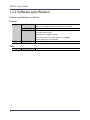
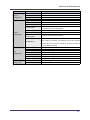
1.2.2 Software speci�cation
Software speci�cation is as follows:
Protocol
TCP/IP
Network Layer
FLDP
ARP , RARP , IPv4 , ICMP
Multicast : IPv4 Organization Local Scope 239.192.0.0/14
TCP , UDP
TELNET , BOOTP , DHCP , HTTP , UPnP ,
JCP (proprietary #19541) ,
RTP (proprietary #50001 - #65535) ,
MVDS Announcement Protocol (proprietary #50000)
SX-RPC (proprietary via HTTP/RTP)
For �rmware version up
Data Transfer Protocol
Proprietary
Transport Layer
Application Layer
Others
Other
Serial
6
1.Product Overview
1.2.3 Interface speci�cation
Interface speci�cation is as follows:
Video
Interface
Codec
Resolution
Flame rate
Con�guration
Others
Analog RGB (15pin Dsub)
JPEG2000
1280 x 768 pixel (WXGA)
30 fps (MAX)
Video Adjustment(Contrast , Bright , Position etc…)
Startup screen, Stop signal screen, Maintenance screen
(Display a still image speci�ed in each mode.)
Audio
Interface
Codec
Sampling rate
Stereo mini jack
16bit PCM
32 (KHz)
Serial Data
Baud rate
Bit length
Stop bit
Parity
Flow Control
Timeout
300 , 600 , 1200 , 2400 , 4800 , 9600 , 14400 , 19200 , 38400 , 57600 , 115200 (bps)
8 , 7 (bit)
1 , 2 (bit)
NONE , EVEN , ODD
NONE , XON/XOFF , RTS/CTS
50 to 1000(ms)
7
MVDS X-1 User's Guide
1.2.4 Notes on the radio wave
Do not use this product near the following equipment or places.
The following equipment may use the same band. If you use this product near
this equipment, the radio waves from this product and the following devices may
interfere with each other.
- Microwave, scienti�c instruments, pacemaker or other medical equipment.
- Licensed radio station in a factory.
- Small power radio station (a non-licensed radio station).
Do not use this product near a cellular phone, TV or Radio.
A cellular phone, TV, and radio use different radio bands than our product.
Generally if they are used near this product, it will not cause a problem. However,
when near this product, sound or image noise can happen.
If there is reinforced concrete/metal between wireless devices, they may not
connect.
This product can connect through wood or glass, but can have trouble
communicating through reinforced concrete/metal.
Wireless Equipment for 2.4GHz and 5GHz band
This frequency band is used by a microwave, industry, science, medical equipment
and licensed in room or low power (non licensed) radio stations.
- Before you use this equipment, verify that it will not interfere with other
broadcasting.
- If interference happens, stop using the equipment or change the band.
Contact us to discuss ways of avoiding interference (example: create the wall).
8
1.Product Overview
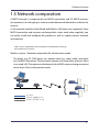
1.3 Network composition
A MVDS network is composed of one MVDS transmitter and 32 MVDS receivers
(at maximum). In each group, a video or audio data are distributed in multicast (or
unicast).
As for network interface, both Wired and Wireless LAN ports are supported. Since
MVDS transmitter and receivers exchange their status each other regularly, you
can easily install and con�gure this product as well as support various network
environment.
- UDP is used as a protocol for data distribution and information exchange.
- Not available via an Internet.
Wireless system - Network composition for Infrastructure mode
The player (e.g. PC, DVD player, etc.) outputs data (e.g. video, audio, serial data,
etc.) to MVDS transmitter. The transmitter captures and sends them to Access Point
via a wired LAN. These data are distributed to the MVDS receivers being connected
to the Access Pint in Infrastructure mode.
AV Cable
Ethernet (100Base, PLC)
Wireless (IEEE802.11a/g)
{
9
MVDS X-1 User's Guide
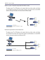
Wireless system - Network composition for Ad-Hoc mode
The player (e.g. PC or DVD player, etc.) outputs data (e.g. video, audio, serial data,
etc.) to MVDS transmitter. The transmitter captures and sends them to the MVDS
receivers being connected to the transmitter in Adhoc mode.
AV Cable
Wireless (IEEE802.11a/g)
{
Network composition for wired connection
The player (e.g. PC or DVD player, etc) outputs data (e.g. video, audio, serial data,
etc.) to MVDS transmitter. The transmitter captures and distributes it to the MVDS
receivers being connected to an Ethernet LAN.
AV Cable
Ethernet (100Base, PLC)
10
1.Product Overview
Network composition for wired/wireless connection mix
If the wired/wireless system are mixed, you can support wider variety of
environment.
AV Cable
Ethernet (100Base, PLC)
Wireless (IEEE802.11a/g)
{
11
MVDS X-1 User's Guide
1.4 Parts and function
The name of each part and the function are explained below:
Front
Transmitter
Push button
MENU
+
SET
12
Description
Go into LCD menu from initial screen.
Return to initial screen from LCD top menu.
Go back to higher level in LCD menu.
Start a factory default con�guration when this button and [SET] button are
pushed together while turning on this product.
Return to previous option in LCD menu.
Select a value to set.
Move to next option in LCD menu.
Select a value to set.
Go into the selected menu in LCD menu.
Enable the selected value.
Start a factory default con�guration when this button and [MENU] button are
pushed together while turning on this product.
1.Product Overview
Receiver
Push button
MENU
+
SET
Description
Start a factory default con�guration when this button and [SET] button are
pushed together while turning on this product.
Not use.
Not use.
Start a factory default con�guration when this button and [MENU] button are
pushed together while turning on this product.
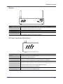
LED (both Transmitter and Receiver)
LED
POWER
STATUS
WIRELESS
ETHER
Description
OFF: Powered off or being on boot process.
ON: Powered on (Normal status)
Blink: Blink every time when codec of 1 frame data is complete.
ON: Factory default con�guration using push buttons is complete.
OFF: Wireless communication is disabled.
Blink: Wireless communication is not established. (Detecting AP or other node,
or unable to connect for wireless con�guration mismatch).
ON: Wireless communication is established.
OFF: Not connected to wired LAN (Not linked)
ON: Connected to wired LAN (Being linked)
13
MVDS X-1 User's Guide
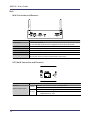
Back
Both Transmitter and Receiver
Part
DCIN 15V1A
ETHER
RS232C
AUDIO
ANALOG RGB
Antenna
Description
AC connector (15V 1A)
* In case of X-1ER, AC power can be supplied via internal DC connector.
Ethernet interface (RJ45)
Serial interface (9pin Male)
Audio interface (3.5mm mini)
RGB interface (D-Sub15pin)
SMA Connector
(Connect the antenna to either or both of the connectors.)
LED (both Transmitter and Receiver)
Ethernet LED
Backside
(Ethernet Connector)
Description
Green
Orange
14
OFF: Not connected to a wired LAN (Not linked)
ON: Connected to a wired LAN (Linked)
Blink: Blink when receiving a packet via wired or wireless LAN.
Flash: Data error in a con�guration area
ROM/RAM check error
2.Installation
2
Installation
15
MVDS X-1 User's Guide
2.1 Before you begin
This section explains the necessary actions that should be taken before you
connect and setup this product.
2.1.1 Necessary items
Please prepare the following items.
MVDS Transmitter
( X-1T )
MVDS Receiver
( X-1R )
PC
(used for setup)
Player
Monitor
Speaker
VGA cable
Audio cable
LAN cable
(used for setup)
Antenna
Con�guration Software
16
One transmitter is required.
As many receivers as you need for your environment. Each receiver supports
one monitor, and up to 32 receivers can be con�gured for use with a single
MVDS transmitter.
A PC with a wired LAN (100BASE-T) port.
A media player with VGA interface and 1280x768 60Hz support (the player
can be a PC or any other device that can output video in the required format
using a VGA interface)
A monitor with VGA interface and 1280 x 768 60Hz support (up to 32
monitors total)
Up to 32 stereo speaker pairs (not necessary if the speaker is embedded in the
monitor above).
VGA cable (male/male) with D-Sub15 pin connector and noise suppression.
One cable is required for each transmitter and each receiver.
Cables with 3.5mm mini plug connector and noise suppression.
One cable is required for each transmitter and receiver.
Category 5 or better LAN cables for connecting the PC to the transmitter and
to the receiver(s) for con�guration purposes.
* Either straight cable or crossover cable can be used as Auto MDI-X is
supported.
* An Ethernet hub can be used, but is not required.
An antenna is required for each transmitter and receiver. The MVDS
transmitters and receivers include 2dB antennas, but you may wish to use
more specialized antennas to provide better performance.
Select the antenna according to your location status, distance from the
receiver or layout.
The MVDS transmitters and receivers have 2 antenna terminals. You can use
both terminals as they automatically recognize which terminal is in use. The
antenna is not required during the installation.
Use AdminManager. You can download AdminManager from the Silex
website:
http://www.silexamerica.com/adminmanager-software-download.html
2.Installation
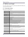
2.1.2 Create environment for setup
The �rst step is to connect the cables to the MVDS transmitter and receiver, and to
the player, monitor(s) and PC. All the con�guration can be performed via a wired
LAN network.
1. Connect the LAN cables
Connect the MVDS transmitter and receiver(s) to the PC using LAN cables.
2. Connect the VGA cables
Connect the player to the MVDS Transmitter, and connect the monitor(s) to the
receiver(s).
3. Connect the audio cables
Connect the player to the MVDS transmitter, and connect the speaker(s) to the
receiver.
4. Power ON
Turn on the MVDS transmitter and receiver, the PC, the player and the
monitor(s) and speakers.
5. Start output from the player
Output a movie (1280 x 768) from the player.
Or to make an adjustment to the screen image at the MVDS transmitter, output
a still image (white or any other light color) from the player.
17
MVDS X-1 User's Guide
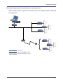
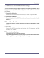
<Connection example>
An example MVDS installation is shown below:
Display
Player
VGA Cable
Audio Cable
VGA Cable
Transmitter
Receiver
LAN Cable
PC
18
Audio Cable
2.Installation
2.2 Con�gure this product
When the cable connections and power on are completed, con�gure the network
settings and adjust the screen images for the MVDS transmitter and receivers.
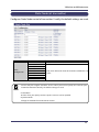
2.2.1 Assign IP address
To simplify the con�guration process, the MVDS transmitter and receivers support
automatic con�guration of the IP address. By default, they attempt to load an
IP address via DHCP when powered on. If no DHCP server is found, then the
transmitter and each of the receivers are loaded with a random IP address of
169.254.xxx.xxx. Note that the same IP address is used for both the wireless and
wired networking functionality.
- If you are using the automatic con�guration process, you may skip to the next section.
Note
If you prefer, you can use Admin Manager to manually assign an IP address for the
MVDS transmitter and for each MVDS receiver:
1. First assign a static IP address to the PC that you are using for setup.
(Example: 10.10.10.10)
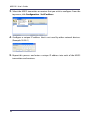
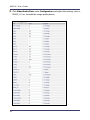
2. When you run the Admin Manager program, a list of the available MVDS
transmitters (model X-1T) and receivers (X-1R) will appear on the main Admin
Manager screen.
19
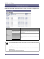
MVDS X-1 User's Guide
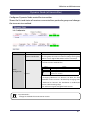
3. Select the MVDS transmitter or receiver that you wish to con�gure. From the
top menu, click Con�guration - Set IP address.
4. Con�gure a unique IP address that is not used by other network devices.
(Example: 10.3.0.1)
5. Repeat this process and enter a unique IP address into each of the MVDS
transmitters and receivers.
20
2.Installation
2.2.2 Con�gure via Web browser
After you have assigned the IP address for each MVDS transmitter and receiver,
you can con�gure these devices using a PC with any standard web browser. For
each MVDS transmitter and receiver, access the Web page using the IP address
you have con�gured into the device. By default the user name is "root" and no
password is set.
To view the IP address of the transmitter and the receivers, you can use the Admin
Manager program.
- When an IP address is set to the transmitter, it can be seen on the front panel.
Note
TIP
- Please note that the PC must be con�gured with a unique IP address that is compatible with
the IP addresses used in the transmitters and receivers (for example, if the transmitter has an
IP address of 169.254.3.111, the PC could have an IP address of 169.254.3.1, assuming that
this address is not used by any of the receivers).
21
MVDS X-1 User's Guide
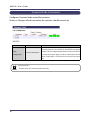
Host name / Password con�guration
Con�gure Host Name and Password.
- Be sure to set a password, especially if you are using the MVDS with a public network.
TIP
In factory default, the last six hexadecimal digits of the Ethernet MAC address is
used as the host name of the MVDS transmitter and receiver(s). You can change
the host name if desired, but make sure that is a unique name.
22
2.Installation
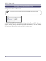
Network con�guration
* Required for both Transmitter and Receivers
Con�gure the IP address and wireless settings. Select Network under
Con�guration in the Web page.
TIP
- The MVDS transmitter and receivers operate without the need to manually con�gure an IP
address as they supports Auto IP function.
- It is impossible to broadcast a movie across a router.
<DHCP, IP, Subnet, Gateway>
Con�gure these settings according to your network environment (by default,
DHCP and the Auto IP function are enabled).
<Wireless>
Select Enable for the Wireless Interface. Select the options for Wireless Mode,
SSID, WEP, etc. appropriate for your environment.
- Be sure to use WEP security, especially if you are using MVDS with a public wireless network.
TIP
23
MVDS X-1 User's Guide
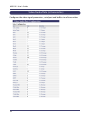
Example: The following are the sample settings to use this product in AdHoc
mode.
Interface
Mode
SSID
Ch.AutoSearch
Channel
DataRate
Authentication
WEP
Key Index
Key Size
WEP Key1
24
Transmitter
Enable
AdHoc
Optional
DISABLE
Optional
36Mbps
Open
ON
1
128bit
Optional
Receiver
Enable
AdHoc
Optional (same as Transmitter)
N/A
N/A
36Mbps
Open
ON
1
128bit
Optional (same as Transmitter)
2.Installation
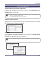
Adjusting a screen image (at transmitter)
Connect to the web page of the transmitter to adjust a screen image appropriate
for the player.
If you are sure of what value to set for screen image, click Video/Audio/Data under
Con�guration and con�gure each setting. If you are not sure what values to set,
you can use the auto-adjustment feature to automatically adjust the screen image.
The use of the auto-adjustment function is described below:
1. Output a still image (white or any other light color) from the player.
2. You can use the default values, however, if you want to make better
adjustment, access the Video/Audio/Data Con�guration page by clicking
Video/Audio/Data under Con�guration, and enter the following values.
Gain
Offset
Filter
32
160
15
3. Select Video/Audio under Tools and click the Start button next to
Maintenance screen mode. Click the Stop button to take effect.
4. Select Video/Audio under Tools and click the Start button next to Video
signal auto con�guration. Auto-adjustment will begin. If the video signal is
not scanned correctly or an error occurs, con�gure it manually.
25
MVDS X-1 User's Guide
5. Click Video/Audio/Data under Con�guration and adjust the settings such as
PHASE_CC, etc. to make the image quality better.
26
2.Installation
Adjusting a screen image (at receiver(s))
TIP
- You normally do not have to adjust a screen image at the receivers since the monitor will
automatically make adjustments.
1. If adjustment is necessary, go to the Web page of the transmitter. Click
Video/Audio under Tools and click the Start button next to Maintenance
screen mode to switch to maintenance mode and output the maintenance
screen to the receivers. The MVDS will automatically adjust the image quality
and position, etc. of the monitor.
2. When the adjustment of the screen image for the monitor is complete, click
Stop button to �nish the maintenance mode.
3. If the adjustment does not go properly, click Video/Audio/Data under
Con�guration and con�gure each value manually.
TIP
- Con�gure each parameter appropriate for your monitor. If incorrect parameters are set, the
monitor may malfunction.
27
MVDS X-1 User's Guide
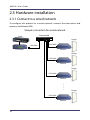
2.3 Hardware installation
2.3.1 Connect to a wired network
To con�gure this product in a wired network, connect the transmitter and
receivers via Ethernet HUB.
Sample connection for wired network
Ethernet HUB
Player
Display
LAN Cable
LAN Cable
Transmitter
Receiver
Display
LAN Cable
Receiver
Display
LAN Cable
Receiver
Display
LAN Cable
Receiver
28
2.Installation
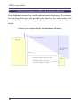
2.3.2 Connect to a wireless network
Below is a sample connection to install this product outdoors.
Select the antenna according to your location status, distance from the receiver or
layout.
29
MVDS X-1 User's Guide
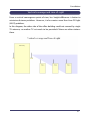
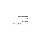
Vertical convergence angle and minimum distance
Every 'high-gain' antenna has vertical and horizontal selectiveness. The narrower
the coverage, the higher the possible gain. However, this selectiveness also
creates 'blind spot' in close range, especially if antennas located in different
height.
30
2.Installation
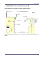
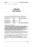
Vertical coverage and Line-of-sight
From a vertical convergence point of view, less height difference is better to
minimize distance problems. However, it also creates more Non-Line-Of-Sight
(NLOS) problems.
In this diagram, the other side of the office building could not covered by single
TX antenna, so another TX set needs to be provided if there are other stations
there.
31
MVDS X-1 User's Guide
32
3.Monitor and Maintenance
3
Monitor and Maintenance
33
MVDS X-1 User's Guide
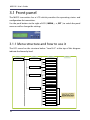
3.1 Front panel
The MVDS transmitter has a LCD which provides the operating status and
con�guration for transmitters.
Use the push buttons to the right of LCD ( MENU, -, +, SET ) to switch the panel
menu as well as change the settings.
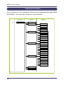
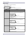
3.1.1 Menu structure and how to use it
The LCD menu has the structure below. "Level 0-3" at the top of this diagram
indicate the hierarchy level.
Level 0
MAIN MENU
Level 1
SERVICE ACTIVITY
Level 2
Level 3
VIDEO
AUDIO
DATA
CONNECTION STAT
ETHERNET
WIRELESS
RTP LINK
DEVICE INFO
HOST NAME
IP ADDRESS
MAC ADDR
F/W VERSION
FPGA VER.
ADMIN MODE MENU
LCD CONTRAST
NETWORK CONFIG
WIRELESS CONFIG
VIDEO CONFIG
SERIAL CONFIG
MAINTENANCE SCR
REBOOT
34
For Level 3 of ADMIN
MODE MENU, refer to
ADMIN MODE MENU
which will come later.
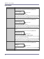
3.Monitor and Maintenance
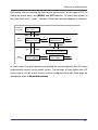
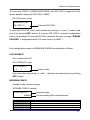
Each menu can be switched by pushing the push buttons to the right of LCD. To
switch the menu levels, use [MENU] and [SET] buttons. To switch the options in
the same level, use [ + ] and [ - ] buttons. The menu transition diagram is as below.
TOP Menu
( Level 0 )
silex X-1T
TX:1 RX:3
MENU
Menu
( Level 1 )
MENU
MAIN MENU
SERVICE ACTIVITY
+
-
SET
MAIN MENU
CONNECTION STAT
SET
MENU
+
-
MENU
To Connection Status Menu
Menu
( Level 2 )
SERVICE:VIDEO
ACTIVE 1280x768
+
-
SERVICE:AUDIO
ACTIVE STEREO
+
-
In each menu, if no push buttons are pushed for a certain period, the LCD menu
automatically returns to the initial screen. The amount of time before the LCD
menu returns to the initial screen can be con�gured from the Wep page by
changing a value at Menu idle timeout.
35
MVDS X-1 User's Guide
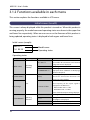
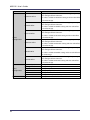
3.1.2 Functions available in each menu
This section explains the functions available in LCD menu.
Initial screen (Level:0)
This screen is always displayed while this product is turned on. When this product is
running properly, the model name and operating status are shown in the upper line
and lower line respectively. When an error occurs or the �rmware of this product is
being updated, operating status is displayed in both upper and lower lines.
Initial screen (sample)
silex X-1T
TX:1 RX:10
Model name
Operating status
Operating status
Upper line
Operating status
Lower line
TX:** RX:****
(Model name)
Operating
normally
Please wait...
*** REBOOTING ***
NO VGA SIGNAL!
(None)
Error
Out of range
V **Hz or H **kHz
EEPROM ERASE....
** F/W UPDATE**
Updating
�rmware
>>>>*
CHK-SUM:XXXX OK!
CHECKSUM ERROR!
36
Details
Normal status
The number of transmitters and receivers
being connected is displayed.
Processing MVDS boot.
Rebooting
Displayed when rebooted via Web page,
Telnet or LCD panel.
No VGA signal is input.
Check the connec tion bet ween the
player(s) and this product.
Incorrect VGA signal
The frequency of the input signal is
displayed in the lower line.
Refresh note error: V **Hz
Resolution error: H **kHz
Please check the output settings of player.
Deleting an old �rmware.
Writing a new �rmware.
The progress is displayed.
Succeeded in the �rmware update.
Failed in the �rmware update.
3.Monitor and Maintenance
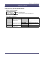
SERVICE ACTIVITY
Shows the service status for each data transfer.
SERVICE ACTIVITY (sample)
SERVICE:VIDEO
ACTIVE 1280x768
Selected menu
Current status of the selected menu
Menu options and status
Menu
VIDEO
Description
Status
Displays a service status for ACTIVE ****x***
video data transfer.
NO SIGNAL
ACTIVE STEREO
AUDIO
Displays the service status for
audio data transfer.
WAIT VIDEO SYNC
SERIAL
Displays the service status for READY
serial data transfer.
ACTIVE
De�nition
Video data is being transferred.
The detected resolution is also
displayed.
No video data is input.
Audio data is being transferred.
Waiting for synchronization with
video data.
Serial data transfer is ready.
Serial data has been transferred.
37
MVDS X-1 User's Guide
CONNECTION STAT
Shows a network status.
CONNECTION STAT (sample)
CONN:ETHERNET
LINK 100Mb/Full
Selected menu
Current status of the selected menu
Menu options and status
Menu
ETHERNET
Description
Status
LINK 100Mb/Full
LINK 100Mb/Half
Show the Ethernet link status. LINK 10Mb/Full
LINK 10Mb/Half
NOT CONNECTED
CONNECTED CH:**
NOT CONNECTED
WIRELESS
Show a wireless link status.
NOT AVAILABLE
DISABLED
RTP LINK
38
Show the link status in RTP
level.
** CLIENT(S)
NOT CONNECTED
De�nition
Communicating via a wired
network. The link speed is also
displayed.
Cable is not connected.
Communicating wirelessly. The
current channel is also displayed.
The wireless connection is
not established for being out
of ser vice area or incor rec t
encryption key.
The wireless communication is
not available since a wireless card
is not detected.
The wireless communication is
disabled by the settings.
The number of receivers in the
group is displayed.
There are no transmitter or
receivers in the group.
3.Monitor and Maintenance
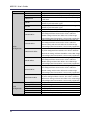
DEVICE INFO
Shows the device information.
DEVICE INFO (sample)
DEV:HOST NAME
TX012345
Selected menu
Current status of the selected menu
Menu options and status
Menu
HOST NAME
IP ADDRESS
MAC ADDR
F/W VERSION
FPGA VER.
Information displayed in the lower line
Show the host name.
Show the IP Address.
Show the Mac Address.
Show the �rmware version.
Show the FPGA version.
39
MVDS X-1 User's Guide
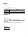
ADMIN MODE MENU
Part of settings can be con�gured, referred and maintained through ADMIN
MODE MENU. This menu has a hierarchic structure below.
Level 1
Level 2
ADMIN MODE MENU
LCD CONTRAST
Level 3
(*)
IP DHCP/BOOTP
NETWORK CONFIG
IP ADDRESS (CFG)
IP SUBNET MASK
IP GATEWAY ADDR
WIRELESS I/F
WIRELESS CONFIG
WIRELESS MODE
SSID
VIDEO CONFIG
CH AUTO SEARCH
(*)
CHANNEL
(*)
DATA RATE
(*)
AUTO CONFIG
(*)
CAPTURE GAIN
(*)
CAPTURE OFFSET
(*)
HORIZONTAL POS
(*)
VERTICAL POS
(*)
PHASE_CC
(*)
BUFFER LEVEL
BAUD RATE (bps)
SERIAL CONFIG
BIT LENGTH
STOP BIT
PARITY
FLOW CONTROL
DATA TIMEOUT
Only the settings with ( * ) can be configured.
40
MAINTENANCE SCR
(*)
REBOOT
(*)
3.Monitor and Maintenance
To enter into LEVEL2 in ADMIN MODE MENU, the PIN CODE is required (In the
factory default setting, the PIN CODE is "0000").
PIN CODE entry screen
ADMIN:PIN CODE
PIN CODE? 0 _ _ _
Enter the PIN CODE.
To enter the PIN CODE, select each number by pushing [ + ] and [ - ] buttons and
save it by pushing [SET] button. If a correct PIN CODE is entered, con�guration
menus are displayed. If a wrong PIN CODE is entered, the error message, "WRONG
PIN CODE!" is displayed and the LCD menu returns to LEVEL 1.
Each con�guration menu in ADMIN MODE MENU are explained as follows.
LCD CONTRAST
Sets a contrast for LCD.
LCD CONTRAST screen
LCD CONTRAST
-> 3 . . . | . . . . .
Enter a value.
Select the value by pushing [ + ] and [ - ] buttons and determine it by pushing
[SET] button.
NETWORK CONFIG
Con�gures the network settings.
NETWORK CONFIG (sample)
IP DHCP/BOOTP
ENABLE
Menu
IP DHCP/BOOTP
IP ADDRESS(CFG)
IP SUBNET ADDR
IP GATEWAY ADDR
Selected menu
Current setting of the selected menu
Information
Displays whether DHCP/BOOTP are enabled or disabled.
Displays an IP Address.
Diplays a Subnet Mask.
Displays a Default Gateway Address.
41
MVDS X-1 User's Guide
WIRELESS CONFIG
Shows or Changes the wireless LAN settings.
WIRELESS CONFIG (sample)
WIRELESS I/F
ENABLE
Menu
WIRElESS I/F
WIRELESS MODE
SSID
CH AUTO SEARCH
Selected menu
Current setting of the selected menu
Information
Displays whether the wireless LAN setting is enabled or disabled.
Displays a wireless LAN mode (AdHoc/Infra.).
Displays the SSID.
Displays or Enables/Disables the channel auto-search function setting.
You can switch to the con�guration screen by pushing [SET] button.
CH AUTO SEARCH *
-> DISABLE
CHANNEL
Select [ENABLE] or [DISABLE] by pushing [ + ] and [ - ] buttons and save it by
pushing [SET] button.
* Reboot this product to take effect.
Displays or Con�gures the wireless channel for Ad hoc mode.
You can switch to the con�guration screen by pushing [SET] button.
CHANNEL
-> 1
DATA RATE
Enter a value.
*
Enter a value.
Select a channel by pushing [ + ] and [ - ] buttons and save it by pushing [SET]
button.
* Reboot this product to take effect.
Displays or Con�gures a transmission dit rate for wireless LAN.
DATA RATE
-> 36 Mbps
*
Enter a value.
Select a value by pushing [ + ] and [ - ] buttons and save it by pushing [SET]
button.
* Reboot this product to take effect.
42
3.Monitor and Maintenance
VIDEO CONFIG
Shows or Con�gures the video settings.
VIDEO CONFIG (sample)
CAPTURE GAIN *
R 128 G 128 B 128
Menu
AUTO CONFIG
Selected menu
Current setting of the selected menu
Information
Starts the auto-adjustment for image parameters.
By pushing [SET] button, you can switch to the auto-adjustment screen.
Push [ + ] and [ - ] buttons to select [OK] (the current setting is enclosed with [ ]).
Push [SET] button to start auto-adjustment.
VGA CONFIG
CANCEL [ OK ]
Select [OK].
The result is displayed in the lower line of LCD. The de�nition of each message
is as follows:
Message
Status
COMPLETE & SAVED
Suceeded in VGA auto-adjustment.
ERR: OUT RANGE
Failed in VGA auto-adjustment.
Incorrect VGA signal is input.
Check that the resolution and refresh note
settings are respectively set to "1280x768" and
"60Hz" in the player(s).
ERR: NO VGA IN
Failed in VGA auto-adjustment.
VGA signal is not input.
Check that a VGA cable is properly plugged
in or player(s) have proper settings to output
video signals.
ERR: SCAN FAILED
Failed in VGA auto-adjustment.
Play another movie or still image at the
player(s) and try the auto-adjustment again.
ERR: N/A
VGA auto-adjustment unavailable
VGA auto-adjustment is not available while
this product is sending a maintenance screen.
Stop sending a maintenance screen and try the
auto-adjustment again.
43
MVDS X-1 User's Guide
VIDEO CONFIG
Menu
CAPTURE GAIN
Information
Displays or Con�gures the Gain value (R/G/B).
You can switch to the con�guration screen by pushing [SET] button.
CAPTURE GAIN
*
R 128 G 128 B 128 s
CAPTURE OFFSET
Set the value in the order of R -> G -> B.
Select a value by pushing [ + ] and [ - ] buttons and determine it by pushing
[SET] button. When one value is determined, the cursor will move to the
other. When the cursor came to "s", push [SET] button to save the settings.
Displays or Con�gures the Offset value (R/G/B).
You can switch to the con�guration screen by pushing [SET] button.
CAPTURE OFFSET *
R 128 G 128 B 128 s
HORIZONTAL POS
44
Enter a value.
Set the value in the order of Position -> Width -> Period.
Each can be a value from 0 to 100, with 50 being the center, less than 50
being minus, and greater than 50 being plus.
Select a value by pushing [ + ] and [ - ] buttons and determine it by pushing
[SET] button. When one value is determined, the cursor will move to the
other. When the cursor came to "s", push [SET] button to save the settings.
Displays or Con�gures the PHASE_CC settings.
You can switch to the con�guration screen by pushing [SET] button.
PHASE_CC
*
-> 0 | . . . . . . . . .
BUFFER LEVEL
Enter a value.
Set the value in the order of R -> G -> B.
Select a value by pushing [ + ] and [ - ] buttons and determine it by pushing
[SET] button. When one value is determined, the cursor will move to the
other. When the cursor came to "s", push [SET] button to save the settings.
Displays or Con�gures the horizontal position (P: Position, W: Width, E: Period)
settings.
You can switch to the con�guration screen by pushing [SET] button.
HORIZONTAL POS *
P 50 W 50 E 50 s
PHASE_CC
Enter a value.
Enter a value.
Select a value by pushing [ + ] and [ - ] buttons and save it by pushing [SET]
button.
Displays the value for retransmission buffer.
3.Monitor and Maintenance
SERIAL CONFIG
Shows the serial settings.
SERIAL CONFIG (sample)
BAUD RATE (bps)
19200
Menu
BAUD RATE (bps)
BIT LENGTH
STOP BIT
PARITY
FLOW CONTROL
DATA TIMEOUT
Selected menu
Current setting of the selected menu
Information
Displays a baudrate.
Displays a bit length.
Displays a stop bit.
Displays a parity bit.
Displays a �ow control setting.
Displays a serial input timeout setting.
MAINTENANCE SCR
Sends or Stops a maintenace screen.
MAINTENANCE SCR screen
MAINTENANCE SCR?
[ STOP ] START
Select [START] or [STOP].
Push [ + ] and [ - ] buttons to select [START] or [STOP] (the current setting is
enclosed with [ ]).
Push [SET] button to send or stop the maintenance screen data.
REBOOT
Reboots this product.
REBOOT screen
REBOOT?
CANCEL
[ OK ]
Select [OK].
Push [ + ] and [ - ] buttons to select [OK] (the current setting is enclosed with [ ]).
Push [SET] button to reboot this product.
45
MVDS X-1 User's Guide
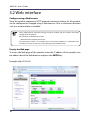
3.2 Web interface
Con�gure using a Web browser
Since this product implements HTTP protocol, advanced settings for this product
can be con�gured or changed using a Web browser. Also, a convenient function
such as a remote reboot is available.
TIP
- To use a Web browser, the TCP/IP settings need to be enabled, and an IP address needs to be
con�gured to this product.
- We recommend a Web browser below.
Microsoft Internet Explorer 6.0 or later
- The explanation below is an example when using Internet Explorer in a Windows Vista
environment. Actual screens may vary depending on your Web browser.
Display the Web page
To access the Web page of this product, enter the IP address of this product into
the address bar of the Web browser and press the ENTER key.
Example: http://10.2.0.4/
46
3.Monitor and Maintenance
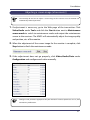
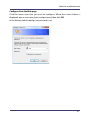
Con�gure from the Web page
Click the menu item that you wish to con�gure. When the screen below is
displayed, type a user name (root) and password, then click OK.
In the factory default settings, no password is set.
47
MVDS X-1 User's Guide
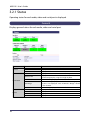
3.2.1 Status
Operating status for each audio, video and serial port is displayed.
General
Displays general status for each audio, video and serial port.
Name
Services
Video
Audio
Data
Status Ethernet Link
Wireless Link
Connection
RTP Clients
RTP Bridge
Device
48
RTP Server Name
Host Name
MAC Address
Firmware Version
FPGA Version
Details
Display a transfer status for video data.
Display a transfer status for audio data.
Display a transfer status for serial data.
Display a wired connection status and link speed.
Display the wireless connection status and channel number.
(Receiver only) Display a signal strength by dbm.
(Transmitter only) Display a number of receivers.
(Transmitter only) Display a number of Wireless Bridge (BR-1,
etc).This is not displayed when no Wireless Bridge is found
on the network.
(Receiver only) Display a host name of transmitter.
Display a host name.
Display the MAC Address.
Display a �rmware version.
Display the FPGA version.
3.Monitor and Maintenance
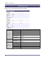
Network
Displays current network status (IP Address and wireless).
Ethernet Status
Name
IP Address
Subnet Mask
Default Gateway
Link Status
SSID
Wireless Status
Channel
RSSI (dbm)
Rate
Encryption Mode
Country Code
Details
Display an IP address.
Display a subnet mask.
Display a default gateway address.
Display a link status.
Display SSID of the wireless network which this product is
connected to.
Display a current channel number.
Display a signal strength.
Display a transmission data rate.
Display the encryption mode being used.
Blank when no connection is made.
Display a country code.
Available wireless bands differ depending on the destination
country.
49
MVDS X-1 User's Guide
Video/Audio/Data
Displays status for each audio, video and serial port.
Video Status
Audio Status
Serial Status
50
Name
Resolution
Frame size (byte)
Interval (ms)
FPS
Frame count (frame)
Details
Display a capture resolution.
Display a data size of the last frame.
Display a capture interval.
Display a frame rate.
Display a number of the captured frame.
Display a number of codec error (the errors noti�ed from
Codec error count
codec chip).
(Receiver only) Display a number of frame that could not be
Frame lost count
captured.
Sampling Rate
Display PCM sampling rate.
(Receiver only) Display a number of data that could not be
Data lost count
received.
Baudrate (bps)
Display a baudrate.
Bit length
Display a bit length.
Stop bit
Display a stop bit.
Parity
Display a parity bit.
Flow control
Display a �ow control.
Transmitted data count Display a number of transmitted data.
Received data count
Display a number of received data.
3.Monitor and Maintenance
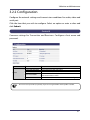
3.2.2 Con�guration
Con�gure the network settings and transmission conditions for audio, video and
serial port.
Click the item that you wish to con�gure. Select an option or enter a value and
click Submit.
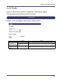
General
Common settings for Transmitter and Receivers. Con�gure a host name and
password.
Device
Name
Host Name
Change root Password
LCD Contrast
Menu idle timeout
PIN CODE
Details
Set a host name.
Set passwords for Web and Telnet.
Set a contrast for LCD.
Set the amount of time before the LCD menu returns to the
initial screen when it is idle.
Set a PIN CODE to limit an access to LCD menu con�guration.
- Be sure to set a password, especially if you are using the MVDS with a public network.
TIP
51
MVDS X-1 User's Guide
Network
Con�gures the network settings.
52
3.Monitor and Maintenance
Ethernet
Con�guration
Name
DHCP/BOOTP
IP Address
Subnet Mask
Default Gateway
Wireless Interface
Wireless Mode
SSID
Ch Auto Search
Wireless
Con�guration
Channel
Data Rate
Network
Authentication
SSID Broadcast
WEP
Con�guration
WPA
Con�guration
WEP
Key Index
Key Size
WEP Key1
WEP Key2
WEP Key3
WEP Key4
WEP Encryption Mode
Pre-Shared Key
Details
Enable/Disable a DHCP function.
Set an IP Address.
Set a Subnet Mask.
Set a Default Gateway.
Enable/Disable the wireless.
Select the wireless connection mode.
Specify the SSID.
(Transmitter only) Enable/Disable the function to search for
an available channel automatically.
(Transmitter only) Specify a channel to use.
Specify a transmission bit rate.
Specify an authentication method.
(Receiver only) Enable/Disable SSID broadcast.
If this setting is disabled, this product will not be searched
by other PCs over a wireless network. It allows to limit an
access to MVDS network.
Enable/Disable the WEP.
Specify an index number for WEP key.
Specify a key length for WEP key.
Specify the WEP key (index number:1).
Specify the WEP key (index number:2).
Specify the WEP key (index number:3).
Specify the WEP key (index number:4).
Select an encryption mode of WPA.
Specify the Pre-Shared Key.
53
MVDS X-1 User's Guide
Video/Audio/Data (at transmitter)
Con�gures the video signal parameters, serial port and buffer size of transmitter.
54
3.Monitor and Maintenance
Name
Capture Timing
Video
Con�guration
Gain R
Gain G
Gain B
Filter R
Filter G
Filter B
Offset R
Offset G
Offset B
H.Position
H Width
H Period
V.Position
V Width
V Period
PLLGAIN_H
PLLGAIN_L
PLLDIV
CLPDLY
CLPDUR
HSOPW
SYNC_CTRL
PHASE_CC
Details
Vertical frequency / (1+x) = FPS
Example: 60[Hz]/(1+[capture timing]2)= 20[fps]
Adjust a red gain.
Adjust a green gain.
Adjust a blue gain.
Adjust a red �lter.
Adjust a green �lter.
Adjust a blue �lter.
Adjust a red offset.
Adjust a green offset.
Adjust a blue offset.
Specify a horizontal position.
Specify a width of horizontal synchronization signal by dot clock.
Specify a period for horizontal synchronization by dot clock.
Specify a vertical position.
Specify a width of vertical synchronization signal by
horizontal synchronization signal.
Specify a period for vertical synchronization signal by
horizontal synchronization signal.
Specify the PLLGAIN VCO Range.
Specify the PLLGAIN Charge Pump Current.
Specify the ADC PLL Divider ratio. Usually, equivalent to the
value of H.Period minus one.
Specify the Clamp Pulse Delay.
Specify the Clamp Pulse width.
Specify a pulse width of ADC HSOUT.
Perform a synchronization control.
Specify the PHASE for image sampling.
55
MVDS X-1 User's Guide
Name
H.Position Offset
H.Width Offset
H.Period Offset
Video
Con�guration
V.Position Offset
V.Width Offset
V.Period Offset
Serial
Con�guration
Buffer
56
Baudrate (bps)
Bit length
Stop bit
Parity
Flow control
Data timeout
Buffer Level
Details
Displays the offset value for H.Position setting that you may
have con�gured from LCD menu.
This value is added to H.Position setting and then take effect
in the video image.
Displays the offset value for H.Width setting that you may
have con�gured from LCD menu.
This value is added to H.Width setting and then take effect
in the video image.
Displays the offset value for H.Period setting that you may
have con�gured from LCD menu.
This value is added to H.Period setting and then take effect
in the video image.
Displays the offset value for V.Position setting that you may
have con�gured from LCD menu.
This value is added to V.Position setting and then take effect
in the video image.
Displays the offset value for V.Width setting that you may
have con�gured from LCD menu.
This value is added to V.Width setting and then take effect in
the video image.
Displays the offset value for V.Period setting that you may
have con�gured from LCD menu.
This value is added to V.Period setting and then take effect
in the video image.
Specify a baudrate.
Specify a bit length.
Specify a stop bit.
Specify a parity check method.
Specify a �ow control method.
Specify a serial input timeout by millisecond.
Specify the number of buffer for retransmission.
3.Monitor and Maintenance
Video/Audio/Data (at receiver)
Con�gures the video signal parameters, serial port and buffer size of receivers.
57
MVDS X-1 User's Guide
Name
H Width
H Period
H Back Porch
V Width
V Period
V Back Porch
H.Width Offset
H.Period Offset
Video
Con�guration
H.Back Porch Offset
V.Width Offset
V.Period Offset
V.Back Porch Offset
Serial
Con�guration
Buffer
58
Baudrate (bps)
Bit length
Stop bit
Parity
Flow control
Data timeout
Buffering Level
Details
Specify a width of horizontal synchronization signal by dot clock.
Specify a period for horizontal synchronization by dot clock.
Specify the Back Porch of horizontal synchronization signal
by dot clock.
Specify a width of vertical synchronization signal by
horizontal synchronization signal.
Specify a period for vertical synchronization signal by
horizontal synchronization signal.
Specify the Back Porch by horizontal synchronization signal.
Displays the offset value for H.Width setting that you may
have con�gured from receivers. This value is added to
H.Width setting and then take effect in the video image.
(* The con�guration from receiver is not currently supported.)
Displays the offset value for H.Period setting that you may
have con�gured from receivers. This value is added to
H.Period setting and then take effect in the video image.
(* The con�guration from receiver is not currently supported.)
Displays the offset value for H.Back Porch setting that you
may have con�gured from receivers. This value is added to
H.Back Porch setting and then take effect in the video image.
(* The con�guration from receiver is not currently supported.)
Displays the offset value for V.Width setting that you may
have con�gured from receivers. This value is added to
V.Width setting and then take effect in the video image.
(* The con�guration from receiver is not currently supported.)
Displays the offset value for V.Period setting that you may
have con�gured from receivers. This value is added to
V.Period setting and then take effect in the video image.
(* The con�guration from receiver is not currently supported.)
Displays the offset value for V.Back Porch setting that you
may have con�gured from receivers. This value is added to
V.Back Porch setting and then take effect in the video image.
(* The con�guration from receiver is not currently supported.)
Specify a baudrate.
Specify a bit length.
Specify a stop bit.
Specify a parity check method.
Specify a �ow control method.
Specify a serial input timeout by millisecond.
Specify the number of buffer for retransmission.
3.Monitor and Maintenance
Static Node (at transmitter)
Con�gures Static Node control of transmitter. Usually, the default settings are used.
Node
Con�guration
Note
Name
Node List Method
Static Node 0
Static Node 1
Static Node 2
Static Node 3
Static Node 4
Static Node 5
Static Node 6
Static Node 7
Details
Specify a node search method.
Specify an IP address for node when Node List Method is set
to Static.
- Use this only for irregular situations such as when you need to specify the node for your
network environment. Usually, the default settings are used.
<Static Node>
Use this when you specify receivers. Up to 8 receivers can be speci�ed.
<Dynamic Node>
Change the method of transmission to receiver.
59
MVDS X-1 User's Guide
Static Node (at receiver)
Con�gures Static Node control for receivers. Usually, the default settings are used.
Name
Node List Method
Switch source interval
Node
Con�guration
Static Node 0
Static Node 1
Static Node 2
Static Node 3
Static Node 4
Static Node 5
Static Node 6
Static Node 7
Details
Specify a node search method.
Set a time inter val to switch the MVDS transmitter
automatically when two or more transmitters are installed
to the network.
Specify an IP address for node when Node List Method is set
to Static.
- Use this only for irregular situations such as when you need to specify a node for your
network environment or you need to switch the transmitter every certain period of time.
Note Usually, the default settings are used.
<Static Node>
Use this when you specify the contents (transmitter) or switch it every certain period of time.
<Dynamic Node>
Use this when you switch the group manually.
60
3.Monitor and Maintenance
Dynamic Node (at transmitter)
Con�gures Dynamic Node control for transmitter.
Shows the list and status of receivers connected to a particular group and changes
the transmission method.
Name
Dynamic Coordinators
Details
Display a list of the discovered groups. The group number in
red is the group where the transmitter belongs to. The group
number is last 8 digits of Mac Address of the transmitter.
Display a list of receivers. Also, the method to transfer data
to receivers can be switched here.
Name
Multicast
Unicast
Node
Con�guration
Devices
OFF
Details
Distributing data in multicast.
Distributing data in unicast.
Receiving data from other transmitter, or data
distribution is disabled.
By changing "Multicast" or "Unicast" to "OFF", the data
distribution to the receiver is disabled. By changing "OFF"
to "Multicast" or "Unicast", the distribution is enabled (the
receiver is added to the group).
"RSSI" indicates a signal strength of each receiver.
Note
<Dynamic Node>
Change the method of transmission to receiver.
61
MVDS X-1 User's Guide
Dynamic Node (at receiver)
Con�gures Dynamic Node control for receivers.
Shows or Changes which transmitter the receivers should connect to.
Name
Node
Con�guration
Note
62
Dynamic Coordinators
Details
Display the list of discovered groups. The group where the
receiver belongs to is checked on its radio button. The group
number is the last 8 digits of MAC Address of the transmitter.
To switch to the other group, check the radio button of that
group. If "No group" is checked, the receiver will not receive
data.
<Dynamic Node>
Use this when you switch the group manually.
3.Monitor and Maintenance
3.2.3 Tools
Performs reboot, factory default con�guration and �rmware update.
Click the button of item that you wish to execute.
Common
Reboots, resets and updates the �rmware of this product.
Reset menu
Firmware
Update
Name
Reboot
Restore to Factory
Default
Details
Reboot this product.
Reset this product to the factory default settings.
Please note that IP address is also reset after the reboot.
-
Load a new �rmware released by Silex into this product.
63
MVDS X-1 User's Guide
Video/Audio (at transmitter)
Adjusts the screen image for transmitter and changes the maintenance screen to
be displayed for receivers.
The screen currently being captured can be applied as a maintenance screen.
Name
Details
Refresh
Manage custom
screen
Tx device tool
TIP
64
Refreshes the Web page.
Check a radio button of the screen you wish to con�gure.
Maintenance mode
By clicking the data size, you can download the image.
Captures the image being input and applies to the
Capture
maintenance screen.
Uploads the image data from the PC. The image data that
Upload
can be uploaded are limited to the one that you have
downloaded.
Delete
Deletes the image data.
Maintenance screen Sends the maintenance screen for monitor adjustment to
mode
receivers. Output with Start button and stop with Stop button.
V i d e o s i g n a l a u t o Adjusts the video signal parameters of the transmitter
con�guration
automatically. Click Start to begin.
- To Capture, Upload and Delete the image data, the radio button next to Maintenance
mode needs to be checked.
3.Monitor and Maintenance
Video/Audio (at receiver)
Changes the startup screen and stop signal screen for receivers.
The screen currently being output to monitors from receivers can be captured
and then applied as startup screen and/or stop signal screen of receiver.
Name
Refresh
Startup screen
Stop signal screen
Manage custom
screen
Capture
Upload
Delete
TIP
Details
Refreshes the Web page. (After the capture process below,
the data size status will not be refreshed automatically. By
clicking this button, the Web page can be refreshed.)
Check a radio button of the screen you wish to con�gure.
By clicking the data size, you can download the image.
Captures the image being played and applies to the
selected screen.
Uploads the image data from the PC. The image data that
can be uploaded are limited to the one that you have
captured.
Deletes the image data.
- To Capture, Upload and Delete the image data, the radio button next to Startup screen or
Stop signal screen needs to be checked.
65
MVDS X-1 User's Guide
66
Appendix
A
Appendix
A-1
MVDS X-1 User's Guide
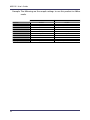
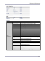
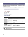
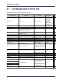
A-1 Con�guration item list
The below is the list of con�guration item:
Parameter name
Description
Value range
Host Name
Set a host name.
Root password
LCD Contrast
Menu idle timeout
Set passwords for Web and Telnet.
Up to 7 characters
Set a contrast for LCD.
0 - 8 (0:Darkest, 8: Lightest)
Set the amount of time before the LCD 0 - 60
menu returns to the initial screen
PIN CODE
IP Address
Subnet Mask
Default Gateway
Wireless Interface
Wireless Mode
SSID
Ch Auto Search
Channel
Data Rate
Network Authentication
SSID Broadcast
WEP
Key Index
Key Size
WEP Key 1
WEP Key 2
WEP Key 3
when it is idle. (1=10sec)
Set a PIN CODE to enter into ADMIN
MODE MENU in LCD.
Set an IP Address.
Set a Subnet Mask.
Set a Default Gateway.
Enable/Disable the Wireless.
Select the Wireless connection mode.
Specify the SSID.
Enable/Disable an available channel
auto-search function.
Specify a Channel to use.
Specify the WEP key.
A-2
Select an encryption mode of WPA.
Transmitter:
"TX" plus the last
6 digits of the
Mac Address
Receivers:
"RX" plus the last
6 digits of the
Mac Address
None
3
18
T R
X X
* *
* *
* * -
0 - 9999
0000
*
-
IP Address
IP Address
IP Address
ENABLE, DISABLE
AdHoc, Infra.
1 - 32 characters
0.0.0.0
0.0.0.0
0.0.0.0
DISABLE
AdHoc
mvds
*
*
*
*
*
*
*
*
*
*
*
*
ENABLE, DISABLE
ENABLE
*
-
(When the location is US:)
1, 2, 3, 4, 5, 6, 7, 8, 9, 10, 11,
1
36, 40, 44, 48, 52, 56, 60, 64,
149, 153, 157, 161, 165
AUTO, 6Mbps, 9Mbps,
Specify a transmission bit rate.
12Mbps, 18Mbps, 24Mbps,
36Mbps, 48Mbps, 54Mbps
Specify an authentication method.
Open, Shared, WPA, WPA2
Enable/Disable SSID Broadcast.
ON, OFF
Enable/Disable the WEP.
OFF, ON
Specify an index number for WEP key. 1 - 4
Specify a key length for WEP key.
64bit, 128bit
When 64bit key is speci�ed:
WEP Key 4
WPA Encryption Mode
Up to 15 characters
Default value
* *
36Mbps
* *
Open
ON
OFF
1
64bit
*
*
*
*
*
None
* *
26 hexadecimal characters or
13 ASCII characters.
TKIP, AES, AUTO
AUTO
* *
10 hexadecimal characters or
5 ASCII characters.
When 128bit key is speci�ed:
*
*
*
*
Appendix
Pre-Shared Key
Codec size
Specify the Pre-Shared Key.
Specify a codec size for 1 frame.
8 - 64 characters
32 - 255
silex technology
64
T
X
*
*
Capture Timing
Vertical frequency / (1+x) = FPS
(Example)
60[Hz]/(1+[capture timing]2)= 20[fps]
1 - 29
2
*
-
Gain R
Gain G
Gain B
Adjust a red gain.
Adjust a green gain.
Adjust a blue gain.
0 - 255
128
*
-
15
*
-
128
*
-
313
*
-
128
* *
1674
* *
192
-
*
21
*
-
7
* *
798
* *
20
-
Parameter name
Filter R
Description
Adjust a red �lter.
Value range
Default value
R
X
*
-
0 - - - 300 MHz
1 - - - 150 MHz
2 - - - 75 MHz
3 - - - 50 MHz
4 - - - 30 MHz
5 - - - 15 MHz
6 - - - 7 MHz
Filter G
Filter B
Adjust a green �lter.
Adjust a blue �lter.
7 - - - 4 MHz
8 - - - 550 MHz
9 - - - 500 MHz
10 - - - 450 MHz
11 - - - 400 MHz
12 - - - 350 MHz
13 - - - reserved
14 - - - reserved
15 - - - 600 MHz
Offset R
Offset G
Offset B
H.Position
H.Width
H.Period
H.Back Porch
V.Position
V.Width
V.Period
V.Back Porch
Adjust a red offset.
Adjust a green offset.
0 - 255
Adjust a blue offset.
Specify a horizontal position.
0 - 65535
Specify a width of horizontal
0 - 65535
synchronization signal by dot clock.
Specify a period for horizontal
0 - 65535
synchronization by dot clock.
Specify the Back Porch of horizontal
0 - 65535
synchronization signal by dot clock.
Specify a vertical position.
0 - 65535
Specify a width of vertical
synchronization signal by horizontal 0 - 65535
synchronization signal.
Specify a period for vertical
synchronization signal by horizontal 0 - 65535
synchronization signal.
Specify the Back Porch by horizontal
0 - 65535
synchronization signal.
A-3
*
MVDS X-1 User's Guide
Parameter name
H.Position Offset
H.Width Offset
H.Period Offset
H.Back Porch Offset
V.Position Offset
V.Width Offset
V.Period Offset
V.Back Porch Offset
50
T R
X X
* -
50
* *
50
* *
50
-
*
50
*
-
50
* *
50
* *
50
-
*
1
*
-
0-7
6
*
-
0 - 65535
1687
*
-
0 - 255
0 - 255
0 - 255
0 - 255
0 - 255
300, 600, 1200, 2400, 4800,
8
32
96
64
0
*
*
*
*
*
-
9600, 14400, 19200, 38400,
57600, 115200
8, 7
1, 2
None, Odd, Even
None, XON/XOFF, RTS/CTS
19200
* *
8
1
None
None
*
*
*
*
100
* *
64
* *
Dynamic
* *
0.0.0.0
* *
Description
Value range
Save the offset value for H.Position 0 - 100
setting that you may have con�gured
from LCD menu.
Save the offset value for H.Width 0 - 100
setting that you may have con�gured
from LCD menu.
Save the offset value for H.Period 0 - 100
setting that you may have con�gured
from LCD menu.
Save the offset value for H.Back Porch 0 - 100
setting that you may have con�gured
from LCD menu.
Save the offset value for V.Position 0 - 100
setting that you may have con�gured
from LCD menu.
Save the offset value for V.Width 0 - 100
setting that you may have con�gured
from LCD menu.
Save the offset value for V.Period 0 - 100
setting that you may have con�gured
from LCD menu.
Save the offset value for V.Back Porch 0 - 100
Default value
setting that you may have con�gured
from LCD menu.
0 : 8-72MHz
PLLGAIN_H
Specify the PLLGAIN VCO Range.
1 : 16-144MHz
2 : 16-144MHz
3 : 24-215MHz
PLLGAIN_L
Specify the PLLGAIN Charge Pump
CLPDLY
CLPDUR
HSOPW
SYNC_CTRL
PHASE_CC
Current.
Specify the ADC PLL Divider ratio.
Usually, equivalent to the value of
H.Period minus one.
Specify the Clamp Pulse Delay.
Specify the Clamp Pulse width.
Specify a pulse width of ADC HSOUT.
Perform a synchronization control.
Specify the PHASE for image sampling.
Baudrate
Specify a baudrate.
Bit length
Stop bit
Parity
Flow control
Specify a bit length.
Specify a stop bit.
Specify a parity check method.
Specify a �ow control method.
Specify a serial input timeout by
50-1000
millisecond.
Specify the number of buffer for
16 - 64
retransmission.
Specify a node search method.
Dynamic, Static
Specify an IP address for node when
IP Address
Node List Method is set to Static.
PLLDIV
Data Timeout
Buffer level
Node List Method
Static Node 0 - 7
A-4
*
*
*
*