1
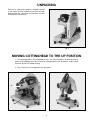
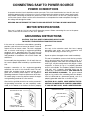
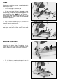
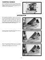
(Model 20-140)
DATED 12-8-95
PART NO. 1349487
©Delta International Machinery Corp. 1995
INSTRUCTION MANUAL
14" Abrasive Cut-Off Saw
TABLE OF CONTENTS
SAFETY RULES . . . . . . . . . . . . . . . . . . . . . . . . . . . . . . . . . . . . . . . . . . . . . . . . . . . . . . . . . . . . . . . . 3
ADDITIONAL SAFETY RULES FOR ABRASIVE CUT-OFF SAWS . . . . . . . . . . . . . . . . . . . . . . . . 4
UNPACKING. . . . . . . . . . . . . . . . . . . . . . . . . . . . . . . . . . . . . . . . . . . . . . . . . . . . . . . . . . . . . . . . . . . 5
MOVING CUTTINGHEAD TO THE UP POSITION . . . . . . . . . . . . . . . . . . . . . . . . . . . . . . . . . . . . . 5
CONNECTING SAW TO POWER SOURCE
Power Connections . . . . . . . . . . . . . . . . . . . . . . . . . . . . . . . . . . . . . . . . . . . . . . . . . . . . . . . . . 6
Motor Specifications . . . . . . . . . . . . . . . . . . . . . . . . . . . . . . . . . . . . . . . . . . . . . . . . . . . . . . . . 6
Grounding Instructions . . . . . . . . . . . . . . . . . . . . . . . . . . . . . . . . . . . . . . . . . . . . . . . . . . . . . . 6
Extension Cords. . . . . . . . . . . . . . . . . . . . . . . . . . . . . . . . . . . . . . . . . . . . . . . . . . . . . . . . . . . . 7
OPERATING CONTROLS AND ADJUSTMENTS
On-Off Switch. . . . . . . . . . . . . . . . . . . . . . . . . . . . . . . . . . . . . . . . . . . . . . . . . . . . . . . . . . . . . . 7
Locking Switch In The “OFF” Position . . . . . . . . . . . . . . . . . . . . . . . . . . . . . . . . . . . . . . . . . 7
Vise . . . . . . . . . . . . . . . . . . . . . . . . . . . . . . . . . . . . . . . . . . . . . . . . . . . . . . . . . . . . . . . . . . . . . . 8
Angle Cutting . . . . . . . . . . . . . . . . . . . . . . . . . . . . . . . . . . . . . . . . . . . . . . . . . . . . . . . . . . . . . . 8
Adjusting Downward Travel Of Abrasive Wheel . . . . . . . . . . . . . . . . . . . . . . . . . . . . . . . . . . 9
Wrench Storage . . . . . . . . . . . . . . . . . . . . . . . . . . . . . . . . . . . . . . . . . . . . . . . . . . . . . . . . . . . . 9
Carrying Handle . . . . . . . . . . . . . . . . . . . . . . . . . . . . . . . . . . . . . . . . . . . . . . . . . . . . . . . . . . . . 9
OPERATION . . . . . . . . . . . . . . . . . . . . . . . . . . . . . . . . . . . . . . . . . . . . . . . . . . . . . . . . . . . . . . . . . . 10
MAINTENANCE
Changing The Wheel . . . . . . . . . . . . . . . . . . . . . . . . . . . . . . . . . . . . . . . . . . . . . . . . . . . . . . . 11
Brush Inspection And Replacement . . . . . . . . . . . . . . . . . . . . . . . . . . . . . . . . . . . . . . . . . . 12
WARRANTY . . . . . . . . . . . . . . . . . . . . . . . . . . . . . . . . . . . . . . . . . . . . . . . . . . . . . . . . . . . . . . . . . . 12
2
SAFETY RULES
Woodworking can be dangerous if safe and proper operating procedures are not followed. As with all machinery, there are certain
hazards involved with the operation of the product. Using the machine with respect and caution will considerably lessen the possibility of personal injury. However, if normal safety precautions are overlooked or ignored, personal injury to the operator may result.
Safety equipment such as guards, push sticks, hold-downs, featherboards, goggles, dust masks and hearing protection can reduce
your potential for injury. But even the best guard won’t make up for poor judgment, carelessness or inattention. Always use common sense and exercise caution in the workshop. If a procedure feels dangerous, don’t try it. Figure out an alternative procedure
that feels safer. REMEMBER: Your personal safety is your responsibility.
This machine was designed for certain applications only. Delta Machinery strongly recommends that this machine not be modified
and/or used for any application other than that for which it was designed. If you have any questions relative to a particular application, DO NOT use the machine until you have first contacted Delta to determine if it can or should be performed on the product.
DELTA INTERNATIONAL MACHINERY CORP.
MANAGER OF TECHNICAL SERVICES
246 ALPHA DRIVE
PITTSBURGH, PENNSYLVANIA 15238
(IN CANADA: 644 IMPERIAL ROAD, GUELPH, ONTARIO N1H 6M7)
WARNING: FAILURE TO FOLLOW THESE RULES
MAY RESULT IN SERIOUS PERSONAL INJURY
15. DON’T OVERREACH. Keep proper footing and balance at all times.
1. FOR YOUR OWN SAFETY, READ INSTRUCTION
MANUAL BEFORE OPERATING THE TOOL. Learn the
tool’s application and limitations as well as the specific
hazards peculiar to it.
16. MAINTAIN TOOLS IN TOP CONDITION. Keep tools
sharp and clean for best and safest performance. Follow
instructions for lubricating and changing accessories.
2. KEEP GUARDS IN PLACE and in working order.
17. DISCONNECT TOOLS before servicing and when
changing accessories such as blades, bits, cutters, etc.
3. ALWAYS WEAR EYE PROTECTION.
4. GROUND ALL TOOLS. If tool is equipped with threeprong plug, it should be plugged into a three-hole electrical
receptacle. If an adapter is used to accommodate a twoprong receptacle, the adapter lug must be attached to a
known ground. Never remove the third prong.
18. USE RECOMMENDED ACCESSORIES. The use of
accessories and attachments not recommended by Delta
may cause hazards or risk of injury to persons.
19. REDUCE THE RISK OF UNINTENTIONAL STARTING. Make sure switch is in “OFF” position before plugging
in power cord.
5. REMOVE ADJUSTING KEYS AND WRENCHES. Form
habit of checking to see that keys and adjusting wrenches
are removed from tool before turning it “on.”
20. NEVER STAND ON TOOL. Serious injury could occur
if the tool is tipped or if the cutting tool is accidentally
contacted.
6. KEEP WORK AREA CLEAN. Cluttered areas and
benches invite accidents.
9. MAKE WORKSHOP CHILDPROOF – with padlocks,
master switches, or by removing starter keys.
21. CHECK DAMAGED PARTS. Before further use of the
tool, a guard or other part that is damaged should be carefully checked to ensure that it will operate properly and
perform its intended function – check for alignment of moving parts, binding of moving parts, breakage of parts,
mounting, and any other conditions that may affect its
operation. A guard or other part that is damaged should be
properly repaired or replaced.
10. DON’T FORCE TOOL. It will do the job better and be
safer at the rate for which it was designed.
22. DIRECTION OF FEED. Feed work into a blade or cutter
against the direction of rotation of the blade or cutter only.
11. USE RIGHT TOOL. Don’t force tool or attachment to
do a job for which it was not designed.
23. NEVER LEAVE TOOL RUNNING UNATTENDED. TURN
POWER OFF. Don’t leave tool until it comes to a complete
stop.
7. DON’T USE IN DANGEROUS ENVIRONMENT. Don’t
use power tools in damp or wet locations, or expose them
to rain. Keep work area well-lighted.
8. KEEP CHILDREN AND VISITORS AWAY. All children
and visitors should be kept a safe distance from work area.
12. WEAR PROPER APPAREL. No loose clothing, gloves,
neckties, rings, bracelets, or other jewelry to get caught in
moving parts. Nonslip footwear is recommended. Wear
protective hair covering to contain long hair.
24. DRUGS, ALCOHOL, MEDICATION. Do not operate
tool while under the influence of drugs, alcohol or any
medication.
13. ALWAYS USE SAFETY GLASSES. Wear safety glasses.
Everyday eyeglasses only have impact resistant lenses;
they are not safety glasses. Also use face or dust mask if
cutting operation is dusty.
25. MAKE SURE TOOL IS DISCONNECTED FROM
POWER SUPPLY while motor is being mounted, connected
or
reconnected.
14. SECURE WORK. Use clamps or a vise to hold work
when practical. It’s safer than using your hand and frees
both hands to operate tool.
26. WARNING: The dust generated by certain woods and
wood products can be injurious to your health. Always operate machinery in well ventilated areas and provide for proper
dust removal. Use wood dust collection systems whenever
3
ADDITIONAL SAFETY RULES FOR
ABRASIVE CUT-OFF SAWS
1. WARNING: Do not operate your abrasive cut-off
saw until it is completely assembled and installed
according to the instructions.
starting cut.
20. AFTER TURNING MACHINE ON, lower wheel lightly
until it comes into contact with the workpiece and then
draw wheel firmly through the cut. DO NOT allow the
wheel to chatter and jump as this may cause the wheel
to wear out of round, resulting in poor cutting and possible broken wheels.
2. IF YOU ARE NOT thoroughly familiar with the operation of abrasive cut-off saws, obtain advice from your
supervisor, instructor or other qualified person.
3. WEAR safety goggles, face shield, respirator, body
apron, headcovering, safety shoes, long tight-fitting
sleeves and gloves.
21. ANY material can be cut more satisfactorily when
placed in position for the wheel to cut with the least arc
of contact.
4. USE ONLY recommended reinforced abrasive wheels
with blotters.
22. THE NUMBER of cuts per wheel, as well as the
quality of cut, may vary considerably with the cutting
time. Fast cuts cause the wheel to wear more rapidly
but also help to reduce discoloration and burr. This is
especially noticeable when cutting light gage tubing.
When coming through the bottom wall, with the longer
arc of contact, do not slow-up but give a vigorous pull.
This keeps the metal from overheating and dragging off
in a heavy burr.
5. TIGHTEN arbor screw and all clamps before operating.
6. MAKE SURE spindle lock is disengaged before
operating.
7. ALWAYS keep guards in place and working properly.
8. KEEP hands clear of cut-off wheel.
23. USE the wheel guard at all times.
9. SECURE workpiece properly. Work should be
straight and firmly clamped to avoid possible movement
and pinching as the cut nears completion.
24. NEVER operate the machine in an area with flammable liquids or gases.
10. NEVER cut anything freehand.
25. TO AVOID electric shock, do not use under damp
conditions or expose to rain.
11. NEVER reach behind or beneath the cut-off wheel.
26. THIS tool is designed for ferrous metals only. DO
NOT attempt to cut wood, masonry, aluminum or magnesium with this tool.
12. MAKE SURE the wheel has come to a complete
stop before removing or securing workpiece or changing
workpiece angle.
27. AFTER installing a new wheel, never start the tool
with a person in line with the wheel. ALWAYS run the
tool for approximately one minute before cutting. If the
wheel has an undetected crack or flaw, it could burst in
less than one minute.
13. MAKE SURE the inside surfaces of the wheel
flanges as well as the sides of the wheel are free from
any foreign matter.
14. WHEN MOUNTING the wheel, care should be taken
to tighten the arbor screw only enough to hold the wheel
firmly and to prevent wheel slippage. Excessive tightening may result in damaging the wheel and springing the
wheel flanges.
28. SHUT OFF power before servicing or adjusting tool.
29. SHOULD any part of your machine be missing,
damaged or fail in any way, or any electrical component
fail to perform properly, shut-off switch and remove plug
from power supply outlet. Replace missing, damaged or
failed parts before resuming operation.
15. USE ONLY abrasive wheels rated at 3900 RPM or
higher.
16. ALWAYS check the wheel for cracks or other damage before operation. Replace cracked or damaged
wheel immediately.
30. ADDITIONAL INFORMATION regarding the safe
and proper operation of this product is available from
the National Safety Council, 1121 Spring Lake Drive,
Itasca, IL 60143-3201 in the Accident Prevention Manual
for Industrial Operation and also in the Safety Data
Sheets provided by the NSC. Please also refer to the
American National Standard Institute ANSI 01.1 Safety
Require-ments for Woodworking Machinery and the
U.S. Depart-ment
of
Labor
OSHA 1910.213
Regulations.
17. USE ONLY wheel flanges specified for your machine.
18. MAKE SURE abrasive wheel is not contacting
workpiece before switch is turned on.
19. ALLOW the motor to come up to full speed before
4
UNPACKING
Your new 14 Abrasive Cut-Off Saw is shipped complete
in one carton. Carefully unpack the saw from the shipping container. Fig. 2 illustrates the saw after it has been
removed from the container.
Fig. 2
MOVING CUTTINGHEAD TO THE UP POSITION
1. For shipping purposes the cuttinghead (A) Fig. 3, has been clamped in the down position by
means of the holddown chain (B). To move the cuttinghead (A) to the up position, simply unhook
the chain (B) from the handle housing.
2. Fig. 4 illustrates the cuttinghead in the up position.
A
B
Fig. 3
Fig. 4
5
CONNECTING SAW TO POWER SOURCE
POWER CONNECTIONS
A separate electrical circuit should be used for your tools. This circuit should not be less than #12 wire and
should be protected with a 20 Amp fuse. Have a certified electrician replace or repair a worn cord immediately. Before connecting the motor to a power line, make sure the switch is in the “OFF” position and be
sure that the electric current is of the same characteristics as stamped on the motor nameplate. Running on
low voltage will damage the motor.
WARNING: DO NOT EXPOSE THE TOOL TO RAIN OR OPERATE THE TOOL IN DAMP LOCATIONS.
MOTOR SPECIFICATIONS
Your saw is wired for 110-120 volt, 60 HZ alternating current. Before connecting the saw to the power
source, make sure the switch is in the “OFF” position.
GROUNDING INSTRUCTIONS
CAUTION: THIS TOOL MUST BE GROUNDED WHILE IN USE
TO PROTECT THE OPERATOR FROM ELECTRIC SHOCK.
In the event of a malfunction or breakdown, grounding
provides a path of least resistance for electric current to
reduce the risk of electric shock. This tool is equipped
with an electric cord having an equipment-grounding
conductor and a grounding plug. The plug must be
plugged into a matching outlet that is properly installed
and grounded in accordance with all local codes and
ordinances.
grounded.
Use only 3-wire extension cords that have 3-prong
grounding types plugs and 3-hole receptacles that
accept the tool’s plug, as shown in Fig. 5.
Repair or replace damaged or worn cord immediately.
Improper connection of the equipment-grounding
conductor can result in risk of electric shock. The conductor with insulation having an outer surface that is
green with or without yellow stripes is the equipmentgrounding conductor. If repair or replacement of the electric cord or plug is necessary, do not connect the equipment grounding conductor to a live terminal.
This tool is intended for use on a circuit that has an outlet
and a plug that looks like the one shown in Fig. 5. A
temporary adapter, which looks like the adapter illustrated in Fig. 6, may be used to connect this plug to a 2-hole
receptacle, as shown in Fig. 6, if a properly grounded
outlet is not available. The temporary adapter should be
used only until a properly grounded outlet can be
installed by a qualified electrician. THIS ADAPTER IS
NOT APPLICABLE IN CANADA. The green-colored
rigid ear, lug, and the like, extending from the adapter,
must be connected to a permanent ground, such as a
properly grounded outlet box, as shown in Fig. 6.
Check with a qualified electrician or service personnel if
the grounding instructions are not completely understood, or if in doubt as to whether the tool is properly
CAUTION: IN ALL CASES, MAKE CERTAIN THE RECEPTACLE IN QUESTION IS PROPERLY GROUNDED.
IF YOU ARE NOT SURE, HAVE A CERTIFIED ELEC-
Do not modify the plug provided - if it will not fit the outlet, have the proper outlet installed by a qualified electrician.
GROUNDED OUTLET BOX
GROUNDED OUTLET BOX
CURRENT
CARRYING
PRONGS
GROUNDING MEANS
ADAPTER
GROUNDING BLADE
IS LONGEST OF THE 3 BLADES
Fig. 5
Fig. 6
6
EXTENSION CORDS
Use proper extension cords. Make sure your extension
cord is in good condition and is a 3-wire extension cord
which has a 3-prong grounding type plug and a 3-hole
receptacle which will accept the tool’s plug When using
an extension cord, be sure to use one heavy enough to
carry the current of the saw. An undersized cord will
cause a drop in line voltage resulting in loss of power
and overheating. Fig. 6A shows the correct gage to use
de-pending on cord length. If in doubt, use the next
heavier gage. The smaller the gage number, the heavier
TOTAL LENGTH OF
CORD IN FEET
GAGE OF EXTENSION
CORD TO USE
0 - 25
26 - 50
51 - 100
101 - 150
14 AWG
12 AWG
Not Recommended
Not Recommended
Fig. 6A
OPERATING CONTROLS AND ADJUSTMENTS
ON-OFF SWITCH
Your 14 Abrasive Cut-Off Saw is provided with an
ON-OFF switch that can be used for INTERMEDIATE
OPERATION or CONTINUOUS OPERATION, as follows:
INTERMEDIATE OPERATION – To turn the saw “ON”
depress switch trigger (A) Fig. 7. To turn the saw “OFF”
release switch trigger (A).
A
Fig. 7
CONTINUOUS OPERATION – Depress switch trigger
(A) Fig. 8, and push in lock button (B). The saw will
remain “ON” until the switch trigger (A) is depressed.
B
A
Fig. 8
LOCKING SWITCH IN
THE “OFF” POSITION
IMPORTANT: We suggest that when the machine is not
in use, the switch be locked in the “OFF” position using
a padlock (C) through the holes in the switch trigger (A),
as shown in Fig. 9.
A
C
7
Fig. 9
VISE
Clamping the workpiece can be accomplished quickly
and easily as follows:
E
1. Lift half-nut (A) Fig.10, off screw (B).
B
2. Pull out screw handle (C) Fig.10, far enough to allow
workpiece (D) to be placed in vise opening against rear
vise clamp (E) as shown. NOTE: It is not necessary to
thread screw handle (C) when the half-nut (A) is in the
raised position. The screw handle (C) can be rapidly
pulled out or pushed in.
A
C
D
Fig. 10
3. Push in on screw handle (C) Fig. 11, until front vise
clamp (F) contacts workpiece (D).
4. Flip half-nut (A) Fig. 11, over to engage screw (B)
and tighten screw handle (C) to securely clamp workpiece (D) in the vise.
D
F
B
A
C
Fig. 11
ANGLE CUTTING
1. Loosen two screws (G) Fig. 12, and rotate rear vise
clamp (H) to the desired angle. Then tighten the two
screws (G). The front vise clamp (F) pivots on its post
and will automatically align itself with the workpiece.
H
G
Fig. 12
2. Fig. 13, illustrates a workpiece clamped in the vise
for a typical angle cutting operation.
8
Fig. 13
F
ADJUSTING
DOWNWARD TRAVEL
OF ABRASIVE WHEEL
A stop screw (A) Fig. 14, is provided to limit the downward travel of the abrasive wheel. This adjustment is
made by loosening lock nut (B) and turning stop screw
(A) in or out as desired. Then tighten lock nut (B).
A
B
Fig. 14
Fig. 15 illustrates edge of the arm casting (C) contacting
stop screw (A), limiting the downward travel of the
abrasive wheel. NOTE: As the abrasive wheel becomes
smaller in diameter (because of wear), the downward
travel of the wheel can be increased.
C
A
Fig. 15
WRENCH STORAGE
A built-in clamp (A) Fig. 16, is provided on the back edge
of the machine base for convenient storage of the
adjusting wrench (B), which is supplied with your
machine.
A
B
Fig. 16
Fig. 17 illustrates the wrench (B) stored in position inside
the clamp.
B
Fig. 17
9
CARRYING HANDLE
B
When transporting the machine, the cuttinghead should
always be locked in the down position by means of the
holddown chain (A) Fig. 18. A carrying handle (B) is provided for ease of transportation.
A
Fig. 18
OPERATION
After clamping the workpiece securely in the vise, turn
the machine on and allow the motor to come up to full
speed. Lower the wheel (A) lightly until it comes into
contact with the workpiece (B), as shown in Fig. 19. Do
not allow the wheel to chatter and jump as this may
cause the wheel to wear out of round, resulting in poor
quality cutting and possible broken wheels.
A
B
Fig. 19
Continue to push firmly down on the handle while the
cut is being made, as shown in Fig. 20
Fig. 20
When coming through the bottom of the cut, as shown
in Fig. 21, do not slow up. This keeps the metal from
overheating and dragging off in a heavy burr.
Fig. 21
10
Fig. 22 illustrates the cut-off piece after the cut is completed. NOTE: The number of cuts per wheel, as well as
the quality of cut, may vary considerably with the cutting
time. Fast cuts cause the wheel to wear more rapidly,
but also help to reduce discoloration and burr.
Fig. 22
MAINTENANCE
CHANGING THE WHEEL
1. DISCONNECT THE MACHINE FROM THE POWER
SOURCE.
2. Rotate the front wheel guard (A) Fig. 23, to the up
position, as shown.
A
Fig. 23
3. Press in on arbor lock (B) Fig. 24, and at the same
time rotate wheel (F) by hand until the arbor lock engages.
4. Using the wrench provided, loosen arbor screw (C)
Fig. 25, by turning it counterclockwise, and remove
arbor screw (C), washer (D), outside wheel flange (E) and
wheel (F). DO NOT REMOVE INSIDE WHEEL FLANGE.
B
5. Make sure the inside surfaces of both the inside and
outside wheel flanges are clean and free from any foreign
substance.
F
6. Install new wheel (F) Fig. 25, outside wheel flange
(E), washer (D) and arbor screw (C). Turn arbor screw (C)
clockwise to tighten. IMPORTANT: USE ONLY
RECOMMENDED REINFORCED ABRASIVE WHEELS
WITH BLOTTERS AND TIGHTEN THE ARBOR SCREW
(C) ONLY ENOUGH TO HOLD THE WHEEL FIRMLY AND
PREVENT WHEEL SLIPPAGE. EXCESSIVE TIGHTENING MAY RESULT IN DAMAGE TO THE WHEEL AND
SPRINGING THE WHEEL FLANGES.
Fig. 24
E D C
7. Rotate front wheel guard to the down position and
make sure spindle lock is disengaged before turning the
machine on.
F
Fig. 25
11
BRUSH INSPECTION
AND REPLACEMENT
CAUTION: BEFORE INSPECTING BRUSHES, DISCONNECT THE MACHINE FROM THE POWER SOURCE.
A
Brush life varies. It depends on the load on the motor.
Check the brushes after the first 50 hours of use for a
new machine or after a new set of brushes has been
installed.
Fig. 26
After the first check, examine them after about 10 hours
of use until such time that replacement is necessary.
The brush holders (A) Fig. 26, are located on the motor
housing opposite each other. Fig. 27, illustrates one of
the brushes removed for inspection. When the carbon
on either brush is worn to 3/16 in length or if either
spring or shunt wire is burned or damaged in any way,
replace both brushes. If the brushes are found serviceable after removing, reinstall them in the same position as
Fig. 27
Two Year Limited Warranty
Delta Machinery
Delta will repair or replace, at its expense and at its option, any Delta machine, machine part, or machine
accessory which in normal use has proven to be defective in workmanship or material, provided that the
customer notifies his supplying distributor of the alleged defect within two years from the date of delivery
to him, of the product and provides Delta Machinery with reasonable opportunity to verify the defect by
inspection. Delta Machinery may require that electric motors be returned prepaid to the supplying distributor or authorized service center for inspection and repair or replacement. Delta Machinery will not be
responsible for any asserted defect which has resulted from misuse, abuse or repair or alteration made or
specifically authorized by anyone other than an authorized Delta service facility or representative. Under no
circumstances will Delta Machinery be liable for incidental or consequential damages resulting from defect
i
v
e
products. This warranty is Delta Machinery’s sole warranty and sets forth the customers exclusive remedy,
with respect to defective products; all other warranties, express or implied, whether of merchantability,
12
PARTS, SERVICE OR WARRANTY ASSISTANCE
All Delta Machines and accessories are manufactured to high quality standards and are serviced by
a network of factory service centers and authorized
service stations listed in your owner’s manual. To
obtain additional information regarding your Delta
quality product or to obtain parts, service or warranty assistance, please call or fax Delta’s toll-free
‘hotline’ number.
Delta maintains a modern, efficient Parts Distribution Center, maintaining an inventory of over
15,000 parts located in Memphis, Tennessee.
Highly qualified and experienced Customer Service Representatives are standing by to assist
you on weekdays from 7:00 A.M. to 5:00 P.M. Memphis time.
Memphis, TN 38118
4290 Raines Road
Phone: (901) 363-8800
800-223-PART
FAX: 800-535-6488
13
14
15
Two Year Limited Warranty
Delta Machinery
Delta will repair or replace, at its expense and at its option, any Delta machine, machine part, or machine
accessory which in normal use has proven to be defective in workmanship or material, provided that the
customer notifies his supplying distributor of the alleged defect within two years from the date of delivery
to him, of the product and provides Delta Machinery with reasonable opportunity to verify the defect by
inspection. Delta Machinery may require that electric motors be returned prepaid to the supplying distributor or authorized service center for inspection and repair or replacement. Delta Machinery will not be
responsible for any asserted defect which has resulted from misuse, abuse or repair or alteration made or
specifically authorized by anyone other than an authorized Delta service facility or representative. Under no
circumstances will Delta Machinery be liable for incidental or consequential damages resulting from defect
i
v
e
products. This warranty is Delta Machinery’s sole warranty and sets forth the customers exclusive remedy,
with respect to defective products; all other warranties, express or implied, whether of merchantability,
16