1
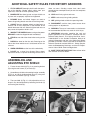
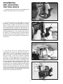
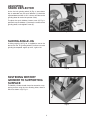
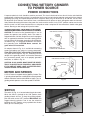
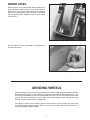
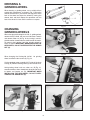
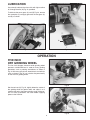
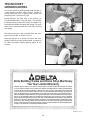
(Model 23-700)
DATED 6-7-96
PART NO. 1340208
©Delta International Machinery Corp. 1996
INSTRUCTION MANUAL
Universal
Wet/Dry
Grinder
SAFETY RULES
Woodworking can be dangerous if safe and proper operating procedures are not followed. As with all machinery, there are certain
hazards involved with the operation of the product. Using the machine with respect and caution will considerably lessen the possibility of personal injury. However, if normal safety precautions are overlooked or ignored, personal injury to the operator may result.
Safety equipment such as guards, push sticks, hold-downs, featherboards, goggles, dust masks and hearing protection can reduce
your potential for injury. But even the best guard won’t make up for poor judgment, carelessness or inattention. Always use common
sense and exercise caution in the workshop. If a procedure feels dangerous, don’t try it. Figure out an alternative procedure that feels
safer. REMEMBER: Your personal safety is your responsibility.
This machine was designed for certain applications only. Delta Machinery strongly recommends that this machine not be modified
and/or used for any application other than that for which it was designed. If you have any questions relative to a particular application, DO NOT use the machine until you have first contacted Delta to determine if it can or should be performed on the product.
DELTA INTERNATIONAL MACHINERY CORP.
MANAGER OF TECHNICAL SERVICES
246 ALPHA DRIVE
PITTSBURGH, PENNSYLVANIA 15238
(IN CANADA: 644 IMPERIAL ROAD, GUELPH, ONTARIO N1H 6M7)
WARNING: FAILURE TO FOLLOW THESE RULES
MAY RESULT IN SERIOUS PERSONAL INJURY
15. DON’T OVERREACH. Keep proper footing and balance
at all times.
1. FOR YOUR OWN SAFETY, READ INSTRUCTION
MANUAL BEFORE OPERATING THE TOOL. Learn the
tool’s application and limitations as well as the specific
hazards peculiar to it.
16. MAINTAIN TOOLS IN TOP CONDITION. Keep tools
sharp and clean for best and safest performance. Follow
instructions for lubricating and changing accessories.
2. KEEP GUARDS IN PLACE and in working order.
17. DISCONNECT TOOLS before servicing and when
changing accessories such as blades, bits, cutters, etc.
3. ALWAYS WEAR EYE PROTECTION.
4. GROUND ALL TOOLS. If tool is equipped with threeprong plug, it should be plugged into a three-hole electrical
receptacle. If an adapter is used to accommodate a twoprong receptacle, the adapter lug must be attached to a
known ground. Never remove the third prong.
18. USE RECOMMENDED ACCESSORIES. The use of
accessories and attachments not recommended by Delta
may cause hazards or risk of injury to persons.
19. REDUCE THE RISK OF UNINTENTIONAL STARTING. Make sure switch is in “OFF” position before plugging
in power cord.
5. REMOVE ADJUSTING KEYS AND WRENCHES. Form
habit of checking to see that keys and adjusting wrenches are
removed from tool before turning it “on.”
20. NEVER STAND ON TOOL. Serious injury could occur
if the tool is tipped or if the cutting tool is accidentally
contacted.
6. KEEP WORK AREA CLEAN. Cluttered areas and
benches invite accidents.
9. MAKE WORKSHOP CHILDPROOF – with padlocks,
master switches, or by removing starter keys.
21. CHECK DAMAGED PARTS. Before further use of the
tool, a guard or other part that is damaged should be carefully checked to ensure that it will operate properly and
perform its intended function – check for alignment of moving
parts, binding of moving parts, breakage of parts, mounting,
and any other conditions that may affect its operation. A
guard or other part that is damaged should be properly
repaired or replaced.
10. DON’T FORCE TOOL. It will do the job better and be
safer at the rate for which it was designed.
22. DIRECTION OF FEED. Feed work into a blade or cutter
against the direction of rotation of the blade or cutter only.
11. USE RIGHT TOOL. Don’t force tool or attachment to do
a job for which it was not designed.
23. NEVER LEAVE TOOL RUNNING UNATTENDED. TURN
POWER OFF. Don’t leave tool until it comes to a complete
stop.
7. DON’T USE IN DANGEROUS ENVIRONMENT. Don’t
use power tools in damp or wet locations, or expose them to
rain. Keep work area well-lighted.
8. KEEP CHILDREN AND VISITORS AWAY. All children
and visitors should be kept a safe distance from work area.
12. WEAR PROPER APPAREL. No loose clothing, gloves,
neckties, rings, bracelets, or other jewelry to get caught in
moving parts. Nonslip footwear is recommended. Wear
protective hair covering to contain long hair.
24. DRUGS, ALCOHOL, MEDICATION. Do not operate
tool while under the influence of drugs, alcohol or any
medication.
13. ALWAYS USE SAFETY GLASSES. Wear safety glasses.
Everyday eyeglasses only have impact resistant lenses;
they are not safety glasses. Also use face or dust mask if
cutting operation is dusty.
25. MAKE SURE TOOL IS DISCONNECTED FROM POWER
SUPPLY while motor is being mounted, connected or reconnected.
26. WARNING: The dust generated by certain woods and
wood products can be injurious to your health. Always operate machinery in well ventilated areas and provide for proper
dust removal. Use wood dust collection systems whenever
possible.
14. SECURE WORK. Use clamps or a vise to hold work
when practical. It’s safer than using your hand and frees
both hands to operate tool.
2
ADDITIONAL SAFETY RULES FOR WET/DRY GRINDERS
1. IF YOU ARE NOT thoroughly familiar with the operation of the Wet/Dry Grinder, obtain advice from your
supervisor, instructor or other qualified person.
these are worn. Grinding creates heat; don’t touch
ground portion of workpiece until you are sure workpiece
has cooled.
2. MAKE SURE the wheel guards and eye shields are
in place and are properly adjusted and tightened.
10. HOLD work firmly against tool rests.
11. KEEP hands away from grinding wheels.
3. BE SURE blotter and wheel flanges are used to
mount the grinding wheels onto the shaft of the grinder.
12. USE grinding wheel suitable for speed of grinder.
4. ADJUST distance between wheels and tool rests to
maintain 1/8" or less separation as the diameter of the
wheels decrease with use. Securely tighten tool rests so
they cannot shift position while in use.
13. DISCONNECT machine from power source when
making repairs or adjustments.
5. INSPECT THE WHEELS before turning on the power.
REPLACE cracked or chipped wheels immediately.
15. ADDITIONAL information regarding the safe and
proper operation of this product is available from the
National Safety Council, 1121 Spring Lake Drive, Itasca,
IL 60143-3201 in the Accident Prevention Manual for
Industrial Operations and also in the Safety Data Sheets
provided by the NSC. Please also refer to the American
National Standards Institute ANSI 01.1 Safety Requirements for Woodworking Machinery and the U.S. Department of Labor OSHA 1910.213 Regulations.
14. WARNING: The use of accessories or attachments
not recommended by Delta may result in risk of injury.
6. STAND to one side of the wheel when turning on the
power.
7. DRESS the wheel on the face only. Dressing on the
side of the wheel would cause it to become too thin for
safe use.
8. WHEN GRINDING use the face of the wheel only.
16. SAVE THESE INSTRUCTIONS. Refer to them often
and use them to instruct others.
9. DO NOT use a wheel that vibrates. Dress wheel,
replace the wheel, or replace the bearings of the shaft if
ASSEMBLING AND
ADJUSTING EYE SHIELD
G
1. Fasten the eye shield (A) Fig. 2, to mounting bracket
(B) using the two screws (C) and nuts (D).
D
B
A
2. Assemble eye shield and mounting bracket assembly
(E) Fig. 3, to side of grinding wheel guard (F) using lock
knob screw and washer (G) Figs. 2 and 3.
3. The eye shield (A) Fig. 4, is fully adjustable so it can
be put in any desired position by loosening lock knob (H)
and moving the shield (A).
C
Fig. 2
E
G
H
F
A
Fig. 3
3
Fig. 4
ASSEMBLING
AND ADJUSTING
THE TOOL RESTS
1. Assemble the tool rest (A) Fig. 5, to the wheel guard
using the lock knob screw (B), nut and washer.
A
B
Fig. 5
2. The tool rest (A) Fig. 6, is adjustable so it can be
positioned as close to the grinding wheel as possible
giving maximum support to the piece that is being
ground, by loosening lock knob (B), moving tool rest (A)
to the desired position and tightening lock knob (B). As
the grinding wheel wears down to a smaller diameter, readjust the tool rest closer to the wheel. The tool rest (A)
should be adjusted so it is set a little below the center of
the wheel. This is the most practical and safest position
for general work. Free hand grinding without the use of
the tool rest should always be done on the lower quarter
of the wheel.
A
B
Fig. 6
E
3. The tool rest for the 10 grinding wheel can be
assembled to the right hand side of the machine as
shown in Fig. 7, or can be assembled to the left hand
side of the machine as shown in Fig. 8. Assemble the
tool rest (C) Figs. 7 and 8 to the machine as desired,
using two 1 long hex head screws and flat washers (D),
one of which is shown. NOTE: When assembling the tool
rest on the left side of the machine, the grinding action
will be on the upward swing. The tool rest (C) Figs. 7 and
8, is adjustable so it can be positioned close to the grinding wheel and at any angle to the wheel by loosening two
locking handles (E), adjusting the tool rest (C), and tightening the two locking handles (E). The locking handles
(E) are spring-loaded and can be repositioned by pulling
outward on each handle and repositioning it on the serrated nut located underneath the handle.
C
D
Fig. 7
C
E
E
D
4
Fig. 8
E
ADJUSTING
SPARK DEFLECTOR
As the five inch grinding wheel (H) Fig. 9, wears down
due to extended use, the spark deflector (J) should be
adjusted downward with it, so it is always set close to the
grinding wheel for maximum operator safety.
J
To adjust the spark deflector, loosen screw (K) Fig. 9,
position the spark deflector (J) close to the surface of the
grinding wheel, and retighten screw (K).
H
K
Fig. 9
SLIDING ANGLE JIG
A
A sliding angle jig (A) Fig. 10, is supplied for use on the
tool rest for the 10 grinding wheel to facilitate accurate
grinding of compound angles up to 45°, right or left.
Fig. 10
FASTENING WET/DRY
GRINDER TO SUPPORTING
SURFACE
The Wet/Dry Grinder should always be secured to a supporting surface using the four mounting holes, three of
which are shown at (A) Fig. 11.
A
A
Fig. 11
5
CONNECTING WET/DRY GRINDER
TO POWER SOURCE
POWER CONNECTIONS
A separate electrical circuit should be used for your tools. This circuit should not be less than #12 wire and should be
protected with a 20 Amp time lag fuse. If an extension cord is used, use only 3-wire extension cords which have 3-prong
grounding type plugs and 3-pole receptacles which accept the tool’s plug. For distances up to 100 feet, use #12 wire.
For distances up to 150 feet, use #10 wire. Have a certified electrician replace or repair damaged or worn cord immediately. Before connecting the motor to the power line, make sure the switch is in the “OFF” position and be sure that the
electric current is of the same characteristics as stamped on motor nameplate. All line connections should make good
contact. Running on low voltage will injure the motor.
GROUNDING INSTRUCTIONS
GROUNDED OUTLET BOX
CAUTION: This tool must be grounded while in use to
protect the operator from electric shock. The motor is
shipped wired for 120 Volt, Single Phase and is equipped
with an approved 3-conductor cord and 3-prong grounding type plug to fit the proper grounding type receptacle,
as shown in Fig. 12. The green conductor in the cord is
the grounding wire. CAUTION: Never connect the
green wire to a live terminal.
CURRENT
CARRYING
PRONGS
GROUNDING BLADE
IS LONGEST OF THE 3 BLADES
An adapter, shown in Fig. 13, is available for connecting
3-prong grounding type plugs to 2-prong receptacles.
THIS ADAPTER IS NOT APPLICABLE IN CANADA.
The green-colored rigid ear, lug, etc., extending from the
adapter is the grounding means and must be connected
to a permanent ground, such as to properly grounded
outlet box, as shown in Fig. 13.
Fig. 12
GROUNDED OUTLET BOX
CAUTION: IN ALL CASES, MAKE SURE THE RECEPTACLE IN QUESTION IS PROPERLY GROUNDED.
IF YOU ARE NOT SURE, HAVE A CERTIFIED ELECTRICIAN CHECK THE RECEPTACLE.
GROUNDING MEANS
ADAPTER
MOTOR AND SPEEDS
A 1/5 H.P. motor is supplied with the Wet/Dry Grinder. The
5 grinding wheel operates at 3450 RPM and replacement
wheels should be rated for 3450 RPM or higher. The 10
grinding wheel operates at the slow speed of 70 RPM.
Fig. 13
SWITCH
The switch (A) Fig. 14, is located under the grinder motor.
When the switch is pushed to the “ON” position, both
grinding wheels will turn. To stop the grinding wheels,
push the switch to the “OFF” position. IMPORTANT: We
suggest when the grinder is not in use, the switch be
locked in the “OFF” position, using a padlock thru the two
holes (B) in the switch plate.
A
B
Fig. 14
6
WATER LEVEL
When using the 10 grinding wheel, there should always
be enough water in the base (A) Fig. 15, of the grinder in
order that one inch of the lower portion of the grinding
wheel will be submerged in water. As water is absorbed
into the grinding wheel, additional water must be added
into the base.
A
Fig. 15
A drain screw (B) Fig. 16, is provided in the grinder base
to remove the water.
B
Fig. 16
GRINDING WHEELS
For best grinding results and to maintain good balance, always keep the wheels properly dressed.
Do not force work against a cold wheel but use light pressure until the wheel becomes warm. It is
earnestly recommended that only balanced wheels be used. The use of balanced wheels adds
years to the life of the bearings in any grinder, and by eliminating the most common source of
vibration, more accurate work is accomplished.
Your dealer can order special wheels, given the size, thickness, arbor diameter and grade, from
any reliable grinding wheel company, but be sure that they are balanced for perfect results and
rated for the proper speed or higher.
7
DRESSING A
GRINDING WHEEL
SILICON CARBIDE
When dressing a grinding wheel, use a suitable silicon
carbide stick type dresser, as shown in Fig. 17. Bring the
dresser forward until it just touches the high point of the
face of the wheel and dress the wheel by moving the
dresser back and forth. Repeat this operation until the
face of the wheel is clean and the corners are square.
GRINDING
WHEEL
STICK
DRESSER
TOOL
REST
Fig. 17
CHANGING
GRINDING WHEELS
A
When changing the Catalog No. 23-702 5 grinding wheel,
remove the eye shield, tool rest and side cover. Loosen
and remove arbor nut (A) Fig. 18, by turning it counterclockwise when viewed from the wheel end of the motor.
To prevent shaft rotation, hold the grinding wheel by
hand, as shown. IMPORTANT: WHEN INSTALLING THE
NEW WHEEL, DO NOT OVERTIGHTEN THE ARBOR
NUT (A).
Fig. 18
When changing the Catalog No. 23-701 10 grinding
wheel, remove the four screws (A) Fig. 19.
Lift the complete motor assembly (A) Fig. 20, off the base
casting (B). Remove bearing block (C) from end of shaft.
A
Hold grinding wheel and turn arbor nut (D) Fig. 21,
counterclockwise, when viewed from wheel end of shaft,
to loosen and remove nut (D). IMPORTANT: WHEN
INSTALLING THE NEW WHEEL, DO NOT OVERTIGHTEN THE ARBOR NUT (D).
A
A
Fig. 19
B
D
C
A
Fig. 20
Fig. 21
8
LUBRICATION
A
Occasionally lubricate the arbor shaft with light machine
oil, through the oiler (A) Fig. 22, provided.
To lubricate the worm gears (A) and (B) Fig. 23, remove
the nameplate (C) and apply grease to the two gears (A)
and (B) as shown.
B
C
A
Fig. 22
Fig. 23
OPERATION
FIVE INCH
DRY GRINDING WHEEL
The five inch diameter aluminum oxide grinding wheel
operates at 3450 RPM and is used for many grinding
operations, such as pointing screwdrivers as shown in
Fig. 24. Scissors, putty knives, wood chisels and drill bits
such as shown in Fig. 25, can also be sharpened easily
on the five inch grinding wheel.
Fig. 24
Set the tool rest (A) Fig. 25, slightly below the center of
the grinding wheel for general work and adjust it so it
supports the tool at the proper grinding angle. Make certain all safety precautions are taken before applying
power to the machine.
A
Fig. 25
9
TEN INCH WET
GRINDING WHEEL
The ten inch aluminum oxide grinding wheel operates at
a slow speed of 70 RPM, which makes it suitable for
honing cutting tools such as garden tools, chisels and
sharpening axes, as shown in Fig. 26.
During operation, the water level in the reservoir (A)
Fig. 26, should be kept at a one inch depth. This will keep
the wheel constantly wet while rotating and keep hardened tools cool without damaging their temper. The large
wheel also is used to remove burrs from tools requiring
keen edges.
A
Fig. 26
The sliding angle jig is used to sharpen tools with compound cutting angles, as shown in Fig. 27.
Adjust the tool rest so it supports the tool at the exact
grinding angle close to the grinding wheel, and observe
all safety precautions before applying power to the
machine.
Fig. 27
Delta Building Trades and Home Shop Machinery
Two Year Limited Warranty
Delta will repair or replace, at its expense and at its option, any Delta machine, machine part, or machine
accessory which in normal use has proven to be defective in workmanship or material, provided that the
customer returns the product prepaid to a Delta factory service center or authorized service station with
proof of purchase of the product within two years and provides Delta with reasonable opportunity to
verify the alleged defect by inspection. Delta may require that electric motors be returned prepaid to a
motor manufacturer’s authorized station for inspection and repair or replacement. Delta will not be responsible for any asserted defect which has resulted from normal wear, misuse, abuse or repair or alteration
made or specifically authorized by anyone other than an authorized Delta service facility or representative.
Under no circumstances will Delta be liable for incidental or consequential damages resulting from defective products. This warranty is Delta’s sole warranty and sets forth the customer’s exclusive remedy, with
respect to defective products; all other warranties, express or implied, whether of merchantability, fitness
for purpose, or otherwise, are expressly disclaimed by Delta.
Printed in U.S.A.
10