1
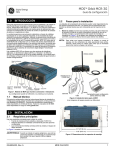
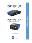
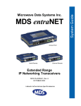
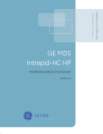
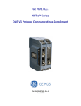
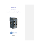
MDS Orbit Series: MCR-4G Setup Guide 1.0 2.2 INTRODUCTION This guide provides installation and startup instructions for the MDS Orbit MCR-4G Managed Connected Router (Figure 1). The MCR-4G is a highly secure, industrial wireless solution for broad based applications, including control center monitoring, well site pad operations, and video surveillance. The MCR-4G provides wireless communication via cellular and WiFi technologies in a single, industrial package, without the need for additional modules or add-ons. In addition, wired serial, Ethernet, and USB interfaces are provided at the front panel, reducing network cost and complexity. MCR-4G units are offered in two different interface offerings; 2 Ethernet/1 Serial (2E1S), or 2 Serial/1 Ethernet (2S1E). The 2E1S configuration is the standard model and is shown here, although most information applies equally to both configurations. Installation Steps Installation details for the product may vary depending on site-specific factors. The steps here provide the basic tasks needed at most sites. 1. Mount the unit. Attach the supplied brackets to the bottom of the case (if not already attached), using the screws provided. Mounting bracket dimensions are shown in Figure 3. If DIN Rail mounting brackets are to be used, consult the Technical Manual for details. NOTE: To prevent moisture from entering the unit, do not mount the case with the cable connectors pointing up. Also, dress all cables to prevent moisture from running along the cables and into the enclosure. Invisible place holder Main Cell Antenna (TX/RX) LED Indicator Panel WiFi Antenna (Cabled) Diversity Cell Antenna (RX) DC INPUT (10-60 Vdc) Mini USB Port DC Power (10-60 Vdc) Ethernet Ports (RJ-45 10/100) COM Port (RJ-45) Cellular Antennas (Aux & Main) SIM Card Slot WiFi Antenna Figure 1. MCR-4G, Connectors & Indicators 1.1 Technical Manual This Setup guide covers basic installation and startup instructions for the unit. A more detailed Technical Manual is also available (05-6628A01). Refer to the Technical Manual for important warnings, cautions, and notes. All GE MDS manuals are available free of charge at www.gemds.com. Serial Ethernet USB PC for Configuration (Serial, Ethernet, USB) Figure 2. Typical MCR-4G Installation Invisible place holder 2.1 INSTALLATION 4.81 (12.22 cm) 2.0 Main Requirements There are three main requirements for installing the unit: • Adequate and stable primary power (10-60 Vdc) • Efficient and properly installed antennas for WiFi and/or Cellular service, as applicable • Correct interface connections between the unit and associated data equipment. Figure 2 shows a typical installation of the MCR-4G. 8.5 (21.59 cm) 9.25 (23.5 cm) WARNING: When the unit is installed in hazardous locations, use only the serial or Ethernet connections on the unit’s front panel. Do not use the USB port in hazardous locations. 05-6702A01, Rev. A Figure 3. Mounting Bracket Dimensions 2. Install the antennas and feedlines. The antennas used must be designed to operate in the appropriate frequency band, and be mounted in a location providing a clear path to the associated station(s). Antennas should be mounted away from large masses of metal and other obstructions. MDS Orbit MCR-4G 1 Often, at least one of the antennas (WiFi or cellular) will be connected directly to one of the coaxial connectors on the unit’s front panel. When remotely-mounted antennas are used, coaxial feedlines should be low loss, and be kept as short as possible. Not all PCs have a serial port. If one is not available, a USB-to-Serial adapter and appropriate driver software may be used to provide serial connectivity. 3. Connect the data equipment. Connection may be made using any combination of Serial protocols (RS-232/RS-485), Ethernet signaling, or USB. Refer to the Technical Manual for wiring details. • Serial connection: Attach data equipment to the front panel COM port. The unit is hardwired as a DCE device, thus a straight-thru cable may be used in most cases (part no. 73-2434A12). • Ethernet connection: Attach data equipment to the front panel ETH1 OR ETH2 port next to the PWR connector. The auto-sensing MDIX feature allows either a straight-thru or crossover cable to be used. • USB connection: Attach data equipment to the front panel mini USB port. The unit supports USB 2.0 with proper drivers installed. 4. Connect primary power. Input power must be 10.0 to 60 Vdc and capable of providing at least 15 watts. A power connector with screw-terminals is provided (see Figure 4). Strip the wire leads to 6 mm (1/4 inch) and insert them into the wire ports. Be sure to observe proper polarity as shown. Tighten the binding screws securely. Lead Binding Screws (2) Wire Ports (2) Retaining Screws (2) (Polarity: Left +, Right –) Figure 4. DC Power Connector CAUTION: The unit is designed for negative-ground power systems only. The power supply should be equipped with NEC Class 2 overload protection, to guard against a short circuit between its output terminals and the unit’s power connector. 2.3 Unit Configuration 2.3.1 Default Settings PC Running Terminal Session To COM Port Figure 5. Setup for PC Configuration—Serial Port (RJ-45 to DB-9 Adapter may be required) 1. Connect a PC to the unit’s COM port and establish a console terminal session using HyperTerminal or a similar program. The following communication parameters must be used: 115200 bps, 8 bits, no parity, one stop bit (8N1), flow control disabled, VT100 emulation. NOTE: The unit may also be configured via Secure Shell (SSH) management. Refer to the Technical Manual for details. 2. Press the ENTER key to receive the login prompt. The COM LED flashes to indicate data communications. 3. Enter the username (admin is the default username) and press ENTER . 4. At the Password prompt, enter the password (admin is the default password). Press ENTER . Upon successful login, the connection message appears. 5. Enter the configuration mode by typing configure followed by the ENTER key. 6. Review and configure all key settings for the required application. Built-in help is available by typing the help command. A summary of all unit settings may be viewed by entering the % show |details command. Tab-completion is a powerful feature that presents CLI users with assistance while typing. Depending on the text that was already entered, tab-completion will display different possible completions. When the Tab key is pressed and no text has been entered, the CLI shows all possible commands that can be typed. As supplied from the factory, units are configured as a “4G WiFi hotspot” with the following configuration settings: • WiFi enabled as an Access Point (AP) • SSID = GEMDS_SERNUM (SERNUM refers to the unit’s serial number, printed on a chassis sticker.) • SSID broadcast enabled • Security = WPA2-PSK, CCMP with passphrase: GEMDS_ORBIT • Default IP address 192.168.1.1 • Cell Enabled (SIM card required; Customer-supplied) • Firewall/NAT/DNS proxy enabled • DHCP server enabled (192.168.1.10 to 192.168.1.20) This configuration allows connection of a laptop PC to the unit via WiFi or the LAN port, and access to the Internet via cellular, if supported by the service plan. Create one-time programmable passwords for device recovery. • Change login passwords (to maintain security). • Evaluate default factory configuration and lock it down to required security level. Refer to the Technical Manual (05-6628A01) for detailed information on above items. NOTE: In areas where cellular service is known to be less than 4G, the LTE Recovery mechanism should be Disabled. Refer to the Technical Manual for details. In-service operation of the unit is completely automatic. The only operator actions required are to apply power and observe the LEDS for proper indications. Table 1 summarizes the unit’s LED functions. 2.3.2 Key items that should be set/reviewed for the unit are: • 7. When finished, log out of the console session and disconnect the PC. 2.4 Initial Checkout Connecting a PC The configuration PC may be connected to the unit by hardwired cable (USB, serial or Ethernet), or by WiFi. The following steps assume a cabled serial connection, as shown in Figure 5. 2 MDS Orbit MCR-4G 05-6702A01, Rev. A 2.4.1 LED Functions 3.0 All units must meet the basic requirements listed below for proper operation. Check these items first when troubleshooting a system problem: • Adequate and stable primary power • Secure connections (antennas, data and power) • A clear transmission path between associated units • An efficient, properly installed antenna system • Proper configuration of unit settings • Correct interface between the unit and other equipment The unit’s LED indicator panel can provide useful information when troubleshooting. Refer to Table 1 for LED indications. Figure 6. LED Status Indicators Table 1: Description of LED Status Indicators LED Name LED State Description PWR (DC Power) Off Solid Green No power to unit Unit is powered, no problems detected Initializing-bootup Alarm indication Solid Amber Fast Blink/Red (1x/sec.) ETH (Ethernet) Off Solid Green Blinking Green No Ethernet link to network Ethernet link present Ethernet traffic in/out COM (Serial Comm. Port) Off Blinking Green No serial connection, or idle Serial traffic in/out NIC1 (Cell) Off Solid Green Solid Amber Solid Red No cellular connection Cell Connection w/RSSI >-80 dBm Cell Connection w/RSSI between -90 & -80 dBm Cell connection w/RSSI<-90 dBm NIC2 (WiFi) Off Interface disabled Access Point Mode Solid Green Operating as AP and at least one client connection Solid Red Operating as an AP and no client connection Off Solid Green No connection Connected with ”good” signal (RSSI stronger than -48 dBm) Connected with “medium” signal (RSSI between -49 & -69 dBm) Connected with ”weak” signal (RSSI less than -70 dBm) Station Mode Solid Amber Solid Red TROUBLESHOOTING 3.1 Event Codes When an alarm condition exists, the unit creates a message readable on a connected PC. Consult the Technical Manual for details. 4.0 COM PORT REFERENCE The COM port (Figure 7) is commonly used to connect an external DTE telemetry device to the unit, supporting either the RS-232 or RS-485 (balanced) format, depending on how the device is configured. The unit supports data rates of 1200, 2400, 4800, 9600, 19200, 38400, 57600, and 115200 bps (asynchronous data only). This connector mates with a standard RJ-45 plug available from many electronics parts distributors. 12345678 4.0.1 Figure 7. COM Connector (RJ-45) As viewed from outside the unit Pin Descriptions—RS-232 Mode Table 2 provides pin descriptions for the COM connector when operating in RS-232 mode. Refer to the Technical Manual for RS-422/485 descriptions. NOTE: In addition to the LEDs above, the Ethernet connector has two embedded LEDs. A flashing green indicates Ethernet data activity. A yellow indicates 100 Mbps operation. Table 2: COM1/COM2 Pin Descriptions—RS-232 Pin Number Input/Output Pin Description 1 Reserved -- 2 OUT DCD (Data Carrier Detect) 3 Reserved -- 4 Ground Connects to ground (negative supply potential) on chassis 5 OUT RXD (Received Data)—Supplies received data to the connected device 6 IN TXD (Transmitted Data)—Accepts TX data from the connected device 7 OUT CTS (Clear to Send) 8 IN RTS (Ready to Send) NOTE: The unit is hardwired as a DCE device 05-6702A01, Rev. A MDS Orbit MCR-4G 3 Hazardous Locations Notice EXPLOSION HAZARD! When installed in hazardous locations, use only the serial and Ethernet connections on the unit’s front panel. Do not use the USB port in hazardous locations. RF Exposure Notice To comply with RF exposure requirements, the antenna shall be installed to ensure a minimum separation distance of 20 cm from persons. The antenna may not be collocated or operated in conjunction with other transmitting devices. Approved Antennas Only approved antennas may be used on the unit's RF output connectors, as listed below. The use of non-approved antennas may result in a violation of FCC rules, and subject the user to FCC enforcement action. Antenna Application GE MDS Part Number WiFi (direct connect), RP SMA 2.4-2.5GHz ANTENNA, 3.2dBi GAIN 97-4278A34 WiFi (external mount) Omni Ant N M Term 2400-2500, 2 dBi 97-4278A48 Cell (direct connect) 960/2170/2700MHz 97-2485A04 Cell (external mount, ground plane) 960/2170/2700MHz, NEEDS GND 97-2485A05 WiFi (Magnetic Mount) 5ft Cable RP SMA Plug 97-4278A78 Warning: Changes or modifications not expressly approved by the manufacturer could void the user’s authority to operate the equipment. FCC Part 15 Notice Operation is subject to the following two conditions: (1) this device may not cause harmful interference, and (2) this device must accept any interference received, including interference that may cause undesired operation. Any unauthorized modification or changes to this device without the express approval of the manufacturer may void the user’s authority to operate this device. Furthermore, this device is intended to be used only when installed in accordance with the instructions outlined in this manual. Failure to comply with these instructions may void the user’s authority to operate this device. Industry Canada Notice This Class A digital apparatus complies with Canadian ICES-003. Cet appareil numérique de la classe A est conforme à la norme NMB-003 du Canada. Servicing Precautions When servicing energized equipment, be sure to wear appropriate Personal Protective Equipment (PPE). During internal service, situations could arise where objects accidentally contact or short circuit components and the appropriate PPE would alleviate or decrease the severity of potential injury. When servicing radios, all workplace regulations and other applicable standards for live electrical work should be followed to ensure personal safety. Manual Revision and Accuracy This manual was prepared to cover a specific version of firmware code. Accordingly, some screens and features may differ from the actual unit you are working with. While every reasonable effort has been made to ensure MDS Orbit MCR-4G Setup Guide 05-6702A01, Rev. A July 2013 (Copyright 2013, GE MDS, LLC) the accuracy of this publication, product improvements may also result in minor differences between the manual and the product shipped to you. If you have additional questions or need an exact specification for a product, please contact GE MDS using the information at the back of this guide. In addition, manual updates can be found on our web site at www.gemds.com. Environmental Information The manufacture of this equipment has required the extraction and use of natural resources. Improper disposal may contaminate the environment and present a health risk due to hazardous substances contained within. To avoid dissemination of these substances into our environment, and to limit the demand on natural resources, we encourage you to use the appropriate recycling systems for disposal. These systems will reuse or recycle most of the materials found in this equipment in a sound way. Please contact GE MDS or your supplier for more information on the proper disposal of this equipment. Product Test Data Sheets Test Data Sheets showing the original factory test results for this unit are available upon request from the GE MDS Quality Leader. Contact the factory using the information at the back of this manual. Serial numbers must be provided for each product where a Test Data Sheet is required. CSA/us Notice This product is approved for use in Class 1, Division 2, Groups A, B, C & D Hazardous Locations. Such locations are defined in Article 500 of the National Fire Protection Association (NFPA) publication NFPA 70, otherwise known as the National Electrical Code. The transceiver has been recognized for use in these hazardous locations by the Canadian Standards Association (CSA) which also issues the US mark of approval (CSA/US). The CSA Certification is in accordance with CSA STD C22.2 No. 213-M1987. CSA Conditions of Approval: The transceiver is not acceptable as a stand-alone unit for use in the hazardous locations described above. It must either be mounted within another piece of equipment which is certified for hazardous locations, or installed within guidelines, or conditions of approval, as set forth by the approving agencies. These conditions of approval are as follows: The transceiver must be mounted within a separate enclosure which is suitable for the intended application.The antenna feedline, DC power cable and interface cable must be routed through conduit in accordance with the National Electrical Code. Installation, operation and maintenance of the transceiver should be in accordance with the transceiver's installation manual, and the National Electrical Code. Tampering or replacement with non-factory components may adversely affect the safe use of the transceiver in hazardous locations, and may void the approval. A power connector with screw-type retaining screws as supplied by GE MDS must be used. EXPLOSION HAZARD! Do not disconnect equipment unless power has been switched off or the area is known to be non-hazardous. Refer to Articles 500 through 502 of the National Electrical Code (NFPA 70) for further information on hazardous locations and approved Division 2 wiring methods. Grounding Requirements To minimize the chance of damage to the unit and connected equipment, a safety ground (NEC Class 2 compliant) is recommended which bonds the antenna system, chassis, power supply, and connected data equipment to a single-point ground, keeping all ground leads as short as possible. Normally, the unit is adequately grounded if the supplied flat mounting brackets are used to mount it to a well-grounded metal surface. If the unit is not mounted to a grounded surface, it is recommended that a safety ground wire be attached to one of the mounting brackets or a screw on the enclosure. The use of a lightning protector is recommended where the antenna cable enters the building; Bond the protector to the tower/support ground, if possible. All grounds and cabling must comply with applicable codes and regulations. GE MDS, LLC 175 Science Parkway Rochester, NY 14620 General Business: +1 585 242-9600 FAX: +1 585 242-9620 Web: www.gemds.com